

Page 1

PFOXIMA»
lJ
D es kt o p
Multimedia LCD Projectors
(Models DP2800 and DP2700)
l: '■
'■fi
/-A/ -a:(' "■
itìiir.
« ji» ¿' O
/•
^TOE|Ei1WriG|S^2
WORKING SESSIÌNS
X,*^., -
' <- •* •* Na
::
MOtBiiilJ
»-f
,y"
srnmi
Page 2
iSuicík
Set:up Procsedures
]. Place the projector on a solid fiat surface at a right angle (perpendicular) to
the projection screen and parallel to the floor.
2. Raise the cover assembly until it clicks into place,
3. Raise the mirror assembly into its fully open position.
For steps 4-7, select the appropriate procedure for your system:
Desktop Computers
4. Turn off the computer, monitor,
and Desktop Projector.
5. Unplug the monitor cable from
the computer and attach it to the
MONITOR end of the "Y" cable.
6. Plug the ”T‘ cable's COM
PUTER (or CPU) end into the
computer’s monitor port.
7. Insert the "Y" cable’s LCD end
into the projector’s COMPUTER
port.
Nocebooks/Lspfcops
4.5.Turn off the computer and the
Desktop Projector.
lug tne
Plug the "Y" cable s COMPUTER (or CPU) end into the
computer’s monitor port.
6. Insert the "Y" cable's LCD end
into the projector’s COMPUTER
port,
7. Attach the Macintosh or VGA
video terminator to the "Y"
cable’s MONITOR end.
Page 3

8. Connccc video and audio sources to the projector:
CONNeCTOPi
PAISIBL
COMPUTER
Both models
Both models
VIDEO liM
DPs?SDD and
OPSTOa witTi
video upgrade
S-VHS
DPSeOO end
DP
2700
wich
video upgrsde
GOMPUTER
AUDO IN
OPSQQO only
AUDIO
m
DPSBOQ only
AUDO OUT
DE^QCX3 only
PUNCTION/CABt-E
Connects computer video
tx3 pro^cdDr-
- VGA video “Y" osple
CCABA-S)
- Macintosh video "y” cable
ICABA-Bi
For Cyclops system
or Pr«ae.ntstiQn Control
Software
- Din B-to-OBS IBM serial
data cabía CCS33-S)
Macintosh AOB date
cable
iaSЭA^Gì
Video input from WTSC.
PAL or SECAM,
• Composita videcysudia
cable tCASV-S)
S-VHS or S-Video Input.
- S-Video cable CCABB-SI
Audio input from computer
or microphone.
- Computer sudic cable
Audio input from
NTSC/PAL^ECAfs/l/S-VHS
source or mterophone.
- Composte vìc^O'^audsa
cable CCA3T-ej
Cannecte an externo!
speaker system.
- Computer audio cable
[GASS-S
3
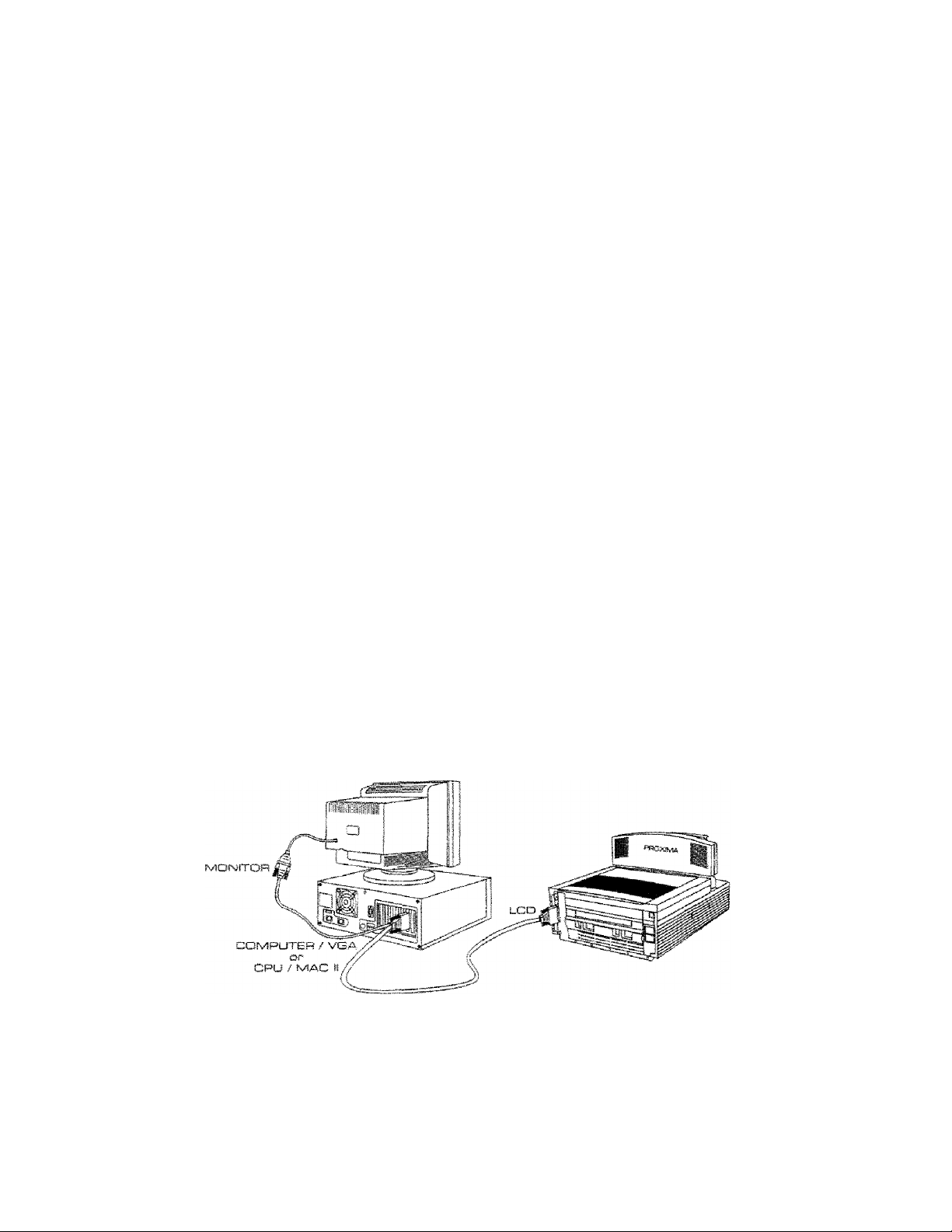
coiMMECTioras
Projector; LCD
MOhitXjr: MONITOR
Mac; CPU/TvIAC II
IBM; COMPUTERA/GA
InstelSadan insixtJGdons
included with Cyclops
system. Q.r ©oftwar«
Projector: VIDEO IN
' Yellow RCA plug
Source: УЮЕО OUT
- Yellow RCA plug
Prolacbor: ViOEO IN
- MiP! ОИ A
Source: ViOEQ OUT
- МИ1 On A
Prolector: COMPUTER
AUDIO IN
- RCA plugs
Source: AUDIO OUT
“ Mini lack
Projectes': L/Я AUOfO IN
• Wt-iise СилЧесЗ tRJ BCA
piuBS
Source; L.« AUOIQ OUT
- Wbice CLiRed tH3 RCA
plugs
Projector: AUDIO OUT
- lack
External Amplifier; UR
AUOO IN
- UR RCA pluga
9.
Power up the Desktop Projector and external monitor before turning on
the computer so that each display is properly sensed during the
computer’s boot-up sequence.
10.
Rotate the projector's focus ring for the clearest displayed image. Use the
tide screen image that appears when you first power up the projector.
Motees The Connector Panel's RS-232 port can be used with the
optional Cyclops interactive pointer system or Proxima’s Presenta
ción Control Software. Installation instructions are included with
Cyclops and the software.
Page 4
с on tira I Panel
cofsí-mc3í_ INUNCTION
VOLUME Adjusts audio level of the projector's intjernal speakers
BROHTNESS
BVNJC Ccmpensetes for fine vaHat^lons in и^Ье diming of dbe
VIDEO
MEÍníU /
ARROWS Makes small adjustments to the projected imege’s position.
0
спретао only}.
lncresses,'‘decreases dhe fcright:nees of tihe projected image-
computer* video signal-
Swidcbes between computer video, NTSC^AL/SECAM
video, or S-VHS.
Press once m display tbe Levels Menu.
Press egsin to displsy the Setup Menu.
Press a third time to exit the Menu WindowHold down for several seconds to initiate CoptionaQ Cyclops
light messuremenc seguence.
Hold down when powering up projector to disabie Cyclops,
Toggles the projection lamp ON/OFF.
Changes Menu Window settings when in MENU mode.
- Press the Right/Left arrow key to move to the setting.
~ Press tbe Up^Down arrow key to change Che setting.
Warnin^Alerf: Light;s
Warning and alert lights located on the projector's control panel provide you
with an indication or the Desktop Projector's operating condition.
CONTROL FUNCmON
aVERTEMP Illuminates in the unlikely event tiie projector reaches an
REPLACE
LAMP
over-fcem paratu re c on diti on.
Illuminates if the active and/or spare projector lamp has
burned out.
Page 5
Levels Menu
[B^HTOESS ^
gtrc: VOJJÆ
IHI
1
Press the MENU/© key to
display the Levels Menu. This
menu varies automatically
based on the t)'-pe of video
source displayed.
coïsrmoî^
BRíQHTNESS jncreases/ciecpeasBs Lhe overall brightness of the projected
SVKJC
VOLUME Adjusts the eudiio leve! of the pnojectohs internsl speaker®
RED
GREEN Adjusts the green cotor signai for computer video.
BLUE
TÎNT
CONTRAST
image.
Compensates for fine variations in tee timing of the
Computer video signal.
cDP^eoa only}.
Adjusts the red color signa! for computer video-
Adjusts the blue color signal for computer video ~
Adjusts the Red and Green color balance for
NTSG/PALySECANVS-VHS video.
Adjusts tee difference between light and dark segments Of
the projected image.
■«»=] iSH
BBtGHTNgSS R TINT Q
WIMI Í I i I
NTSaPADSECAMariJS^mS Vkke
FUÍSICTUOM
Computer ViJgo
COtfTRAST VgjJ.tE
I—«lüi ! ¡HMM [
SeLup Menu
Press the MENU/© key a
second time to display the
Setup Menu.
SOURCE IfMGE
1 VeAS40x4SO 1
1 800 I
1 Ncmm ! i 22B9SÎ 1 FORWATO 1
U^iNGU.^GE 5TORE? SETTINGS
1 ENGUSH 1 hO
COLORS PROECmON
1 FACTORY 1
COMTROL
SOURCE
IMAGE
COLORS
rrdjecton Flips the displayed image for use with a rear projection
FREQUENCY
LANGUAGE
STORE? Seva© aettings currently displayed in bote Menus.
SETTINGS Retrieves factory-set or stored settings, or seves the
Ltste tee name of tee input source detected by the
projector.
Accessible in modes where other choices are avatlable,
based on the type of signal the projector is receiving,
Switches between NORMAL and REVERSE modes-
REVERSE is used primarily for viewing text screens.
Selects tee color mode most suitable for tee proiscted
image.
screen.
Synchronizes the projector wite tee video source.
Note; Adjust SYNC before changing FREQUENCY.
Switches tee language set used in the Menu Window:
English,
current settings.
F^nencti,
German, Italian, and Spanish.
FUPJCTSOISI
Page 6

Remote Control
The Remote Control contains all the key
Rinctions available on the Control Panel and
provides access to additional functions nor
available on the Control Panel or through the
Menu Window.
MEKU
CZl
CYCLOPS
COMTPÌOL FUESICTION
MUTE Toggles sound OFF/ON to the
TEXT Toggles between Qr-aphios mode
REV
PAUSE
intternal end exte.mal speskecs
of 6AO X
mode of TSO x AQQ iines.
DOS text is ees?sr to view
when using Text mode.
Works with Ppoxima's
Presentation Control
Software, which can be used
ta sequence electronic slides.
Detalied ins-trucdons are
included with the software.
-480
lines and Text
- SYNC -f
1—1 1—1
- SF^HTNSSS T
EH CZ3
PROXifWSA*
Desktop Rijiili. *
2700 and 2800
Ssrä feeys = РС^ИАС sdmsré
Getting Help
For technical support, please contact your dealer or call Proxima at:
U.S..A and Canada
CS1 93 ^ST-SSDO
Press 1 for Customer
Service.
fSi 0] CFsxl
Oubaide U.S.A. end Canada
CS1 93 ■45‘7‘-55QO
Press 1 for Customer
Service.
EB1 SI saa-Di T3 efbx3
Europe
+31-43-050 34B
+31-43-В4Э aao срахз
TEW
1 1
- VOLUME +
Ш HD
ИД1
MUTE
о ш
^
Proaima Corporation
Main OfBce:
9440 Carroll Park Drive
San DiegOj GA 92121 -2298
United Scares of America
For Warrant)', Ps-icni and FCC compliance informadon, refer to the Desktop Projector2SÖ0¡2700 User's
Guide.
Proxima and Cyclops are regiscered crademarl'S of Proxima Corpoi^tion, Desktop Projector and trade dress are
trademarks ofProxima Corporation.
In Europei
Horsten^’eg 24
6191 ЮС Беек
The Nerberiands
________
____
PRDXIMÄ
04/94
Page 7
PROXIMA®
Desktop Frepi
■ Model DP2800 and Model DP2700
QUICK
REFERENCE
GUIDE
The Proxima® Desktop Projector™ and Remote Controi:
1) Control Panel
2) Mirror Assembly
3) Internal Speakers (DP2800 only)
4) Cover Assembly
5) Top Air Intake Piker
6) Recessed Carrying Handle
7) Front Air Intake Filters
8) Cyclops Lens
Projection Lens Assembly
9)
and Focus Ring
10) Remote Control
11) Connector Panel
12} Lamp Selector
13) Lamp Chamber Latch
14) Power Cord Receptacle
15) Power Switch
16) Circuit Breaker Reset Button
Page 8

PROXIMA®
D es kt o p
Multimedia LCD Projectors
(Models DP2800 and DP2700)
USER’S GUIDE:
Proxima Desktop Proiector Models
This manual contains information for setting U;
and the Proxima® Desktop Projector” ’
as follows;
• Desktop Projector
•
prupclor
• Desktop Projector2800
• Desktop Projector2700
• Model DP2800
• Mode! DP2700
Both the Desktop Projector 2800 and the Desktop Projeaor 2700 have many aspects in cormnon. Unless
otherwise indicated, the inloiTnation contained within this manual is common to both models. Where controls,
operations, or other aspects differ between models, an ican indicating doe model number appettrs next to the
material chat applies to it. The model number will also be caled out in the body of the text.
up and using the Proxima* Desktop Projector’’''
2700. These projectors are referenced throughout the manual
2800
Page 9

Warranty
LimStatian of
Warranties
FCC
Statement
Proxima Corporation warrants that the Proxima® Desktop Projector™ produa
manufactured by Proxima is free from defects in materials and tsforkiitanship
under normal use during the Warranty Period. The Warrant)' Period com
mences on the day of purchase by the end-user. The Warrant}' Period is one
year. The Desktop Projector lamps are not covered by this W'arraiit)'.
The end-user’s sales receipt or invoice showing the date of purchase of the
product and che name of the Reseller is proof of date of purchase. The Warrant)'
extends only to the origifial. purchaser and is not iransferabk.
During the Warranty Period; Proxima will, at no addiuonai charge, repair or
replace defective parts ot at the option of Proxima, replace the entire unit.
This limited W’arranty does not mend to any Proxima product that has- been
damaged or been rendered defective (a) as a result of accident, misuse or other
abuse; (b) by the use of parts not manufactured or sold by Proxima; (c) by
modificarion of the product; or (d) as a result of servicing by non-audiorized
personnel.
The foregoing W'afranry is expressly in lieu of any other expressed or implied
warranties, including, without limitation, warranties of merchantability or fitness
for a particular purpose. To the extent not prohibited by law, a!! statutory
warranties are hereby waived and excluded from this Warranty. Proxima
expressly disclaims all warranties not stated in this Limited Warranty.
Warning: This equipment gerteraces, uses and can radiate radio frequency energy
and, if not installed and used in accordance with the instruction manual, may
cause interference to radio communications. It has been tested and found to
comply with limits for a Class "A" computing device pursuant to Subpart B of
Part 15 of the FCC Rules, which are designed to provide reasonable protection
against such interference when operated in a cammerciaJ environment. Opera
tion of this equipment in a residential area is likely to cause interference in. which
case the user, at his own expense, will be required to take whatever measures may
be necessary to correct the interference.
T rademarks.
Patents, and
Copyright
Proxima and Cyclops are registered trademarks of Proxima Corporation.
Desktop Projector and trade dress are trademarks of Proxima Corporation. IBM
is a registered trademark of IntemadonaJ Business Machines Corporation.
Macintosh is a registered trademark of Apple Computer, Inc. Other trademarks
are the propert)' of their respective owners. U.S. patent numbers 5,153,568,
5,225,875 and 5,264.835 apply to the Desktop Projector 2700 and Desktop
Projector 2800. U.S. patent number 5,276,436 applies to the Desktop Projretor
2800. Other U.S. and foreign patents are pending.
© Copyright 1994 Proxima Corporation. All rights reserved. Specifications are
subjea to change without notice.
4/94
Page 10

Chapter i
Introducing Che
Proxima®
Desktop
Projector™
Desktop Projector Familv.
................................................... i~2
Cyclops Interactive Pointer System
''X'Tiats in the Box?
................................................................
............
Conl:en1:s
......... 1-2
1-3
Chapter* S
Detailed Setup
Your Proxima Desktop Projector..........................................
Getting Started .......................................................... 2—2
Opening the Projector .......................................
...........2-2
Closing the Projector .......................................................2-7
Transporting the Projector.................................
Connecting the Desktop Projector
COMPUTER
.................................................................
.........................................2-9
.,,....„..2—8
RS-232 ....................................................................... ..2-13
\TOEOIN.................................................................. 2-14
S-WiS
...
.................................................................... 2-15
COMPUTER AUDIO IN
.....
.........................................
AUDIO IN....................................................................
Connecting a Monaural Source ...................................
Connecting a Microphone ................................ ,-.....2—18
AUDIO Oirr............................................................... ,2-lS
Powering Up
Appi)ing Power to the Projector............................
.........................................................................2-21
......
Turning On/Off the Lamp.............................................2-23
Projecting the Image
Image Sire
..........
..............................................
..............................................................
..2—24
.2—24
Focusing.......................................................................
Keystoning
........................................................... ..2-26
2-1
2-10
2-I<5
2-16
2-17
2-21
2-25
Page 11

Chapter 3 The Control Panel
Usingliie The Control Panel Keys
Desktop Arrow Keys
Projector BRIGHTNESS Кда,...........................................................
.............
.........................................................
...........
.........................................................3-2
............................................................
.......
LAMPKer^....................................................................... ...3-2
MENU/0 (QCLOPS) Key.........................................
SYNC Keys .............................................................. .....3-4
\3DEO Key.............................................................. .....3-4
VOLUME Keys............................................................ 3-4
The Menu Settings
Selecting and Changing Settings................................ ...3-3
Saying Changes
Levels Menu................................................................... ....3-6
BRIGHTNESS
SYNC ............................................................................ 3-7
VOLUME
RGB Controls; RED, GREEN & BLUE
TINT......................................................................... 3-7
CONTRAST
Setup Menu
SOURCE
IMAGE...
COLORS
PROlECriON.............................................................
FREQUENCY.............................................................. 3-11
LANGUAGE ................................................................3-11
STORE?............................................................................3-n
SETTINGS .............................................................. Э-12
Waraingand Alert Dghts.................................................. 3-13
OVERTEMP Warning Light....................................... 3-13
REPLACE LAMP Men light
Remote Control .................-................................................
MUTE Key.................................................................... 3-16
TEXT Key.........................................................-........
REV, PAUSE and ¥WD Keys
.............................................................
.......................................................
...............................................................
................................................................
..........................
...
...........................................................
...........................
...
....................................................................
.................................................................... 3-9
..............................................................
................—.
....
..............................
........................................3-16
................
....3-10
3-1
...3-2
3-2
.......3-3
3-5
.,-3-5
3-E
.....3-7
3-7
...3^
........3-8
.3-9
3-10
3-14
3—15
..3-16
Page 12

Chspt:er 4 Cleaning ...................................................................................4-2
Maintenance Projection Lens or Mirror
...............................................4-2
General Maintenance............................................................ 4-3
Swircking Lamps
.............................................................
Replacing Lamps............................................................ 4-4
Changing Air Filters.................................................. 4-7
Changing the Remote Controls Batteries..
...............
Temperature Extremes............................................... 4—12
4-3
4—12
Chapter 5 Troubleshooting Chart
Troubieshooting "^^^re to Get Help
Appendix A
Specifications
Appendix B
Accessories & Replacement Parts
Index
......................................................
.............................................................
5—1
5—4
Page 13
Chapter*
Introducing
the Proxima®
Desktop
Projector™
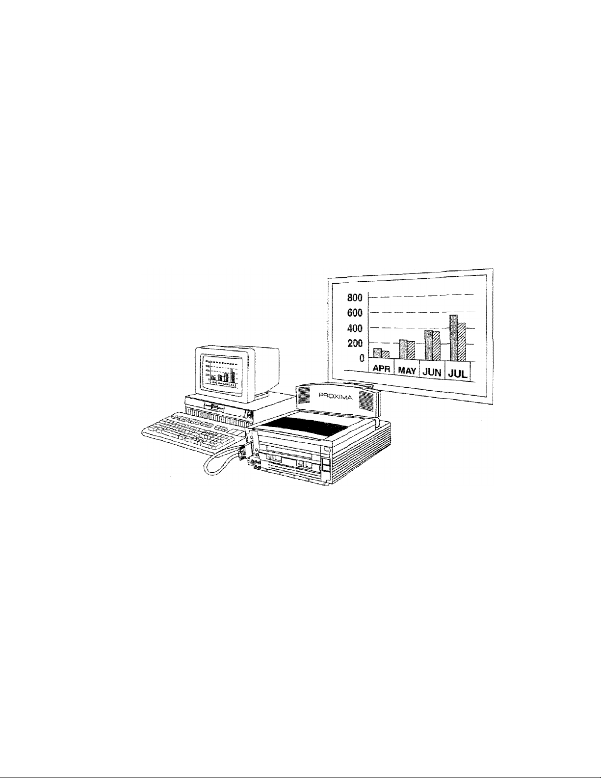
The Proxima Desktop Projector family consists of portable, color
data and video LCD desktop projection products that make
sharing data and presenting information as easy as connecting
your computer to your monitor.
Figure T
The Proxima Desktop Projeccor in use
User's Guide • 1-1
Page 14

Chapter 1 • Introducing the Proxima® Desktop Pnojector
Desktop
Projector
Family
Cyclops
interactive
Pointer
System
The Desktop Projector family includes the following products:
• The Desktop Projector 2800 is a video—ready, active-matrix
multimedia projector for all desktop projection applications.
» The Desktop Projector 2700 is an acttYe-mairix, high-
performance color projector with optional video capabilities.
* The Desktop Projector 2300 is an affordable high quality
color projector for all data desktop projection applications.
This manual covers only the Model DP2800 and the Model
DP2700.
All Proxima Desktop Projectors come Cydops-ready. Cyclops is
an interactive pointer system that functions like a cordless mouse
and lets you control your computer and softw^are from the
projection screen.
ISIote;
You cannot use Cyclops and Proxima’s Presentation
Control Software at the same time. To disable Cyclops aini use
the software, hold the MENU key on the Control Panel down
when you turn the projector power on. This procedure tuiil not
taork with the remote control. To re-enable Cyclops, turn the
projector off and then power it up again.
"1 -2 • User's Guide
Page 15
Chapter 1 • introducing the Proxima*- Dask-fcop Projector
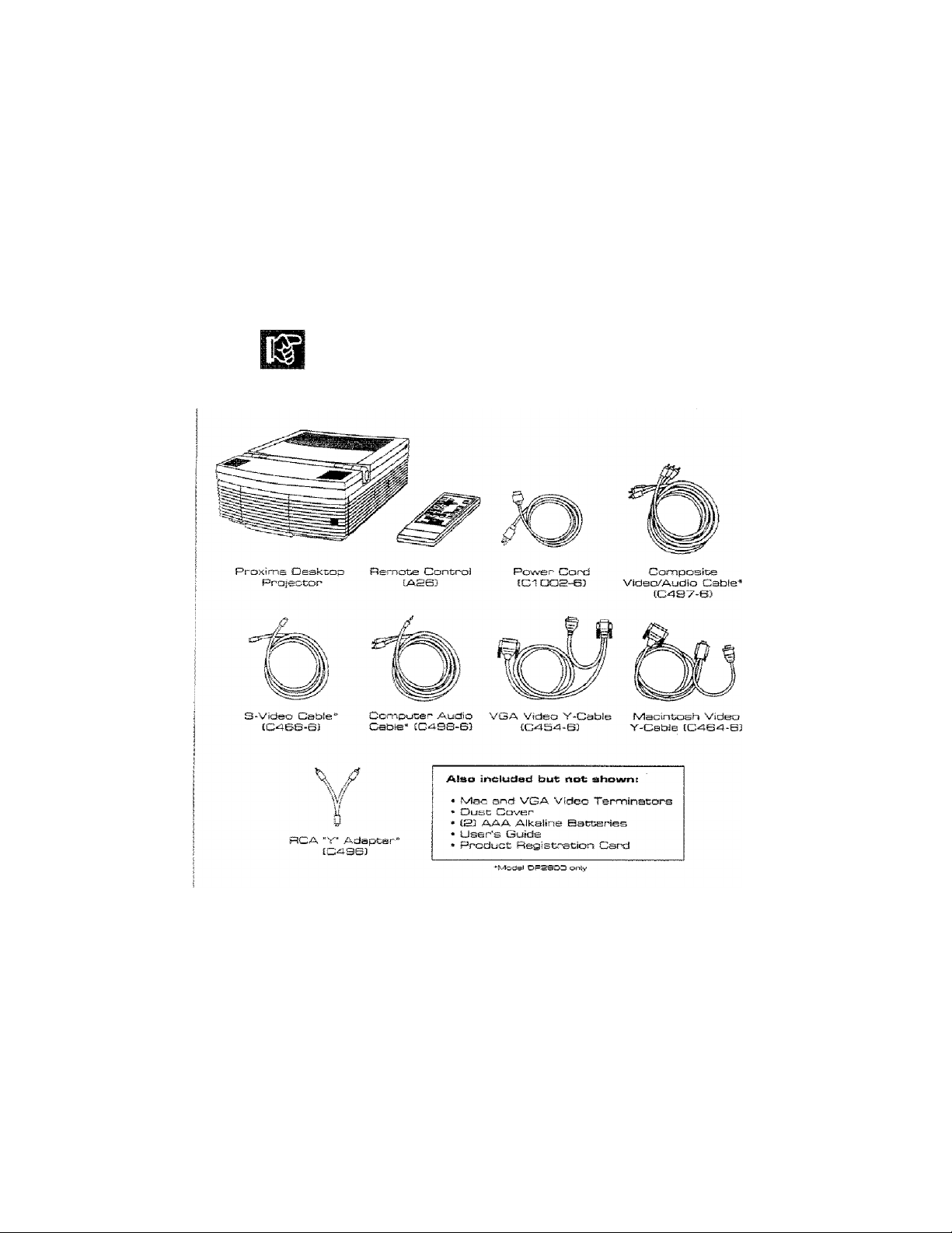
What’s in the
Box?
After you've opened the box and removed the Desktop Projector
and shrink-wrapped accessor)' packs, make sure you have aJi the
items shown in Figure 2.
CAUTiOIM! The Desktop Projector should be treated like any
ocher precision optical instrument. Handle it carefully.
Figure
S
Items inciuded with the Desktop Projector
The internationaJ version has three extra power cords for Europe
(part number Cl003—6), Great Britain (part number Cl011—6),
and Italy (part number Cl012-6).
User’s Guide • 1 -3
Page 16
Chapter 2
Detailed
Setup
Your* Pr*oxima
Oeakt;ctp
Projector
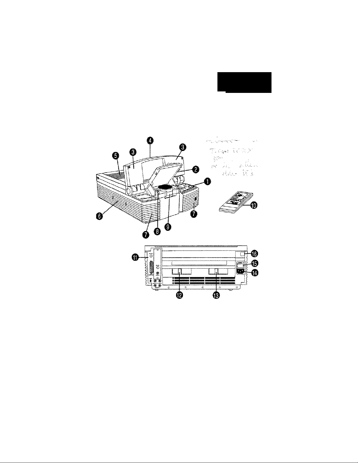
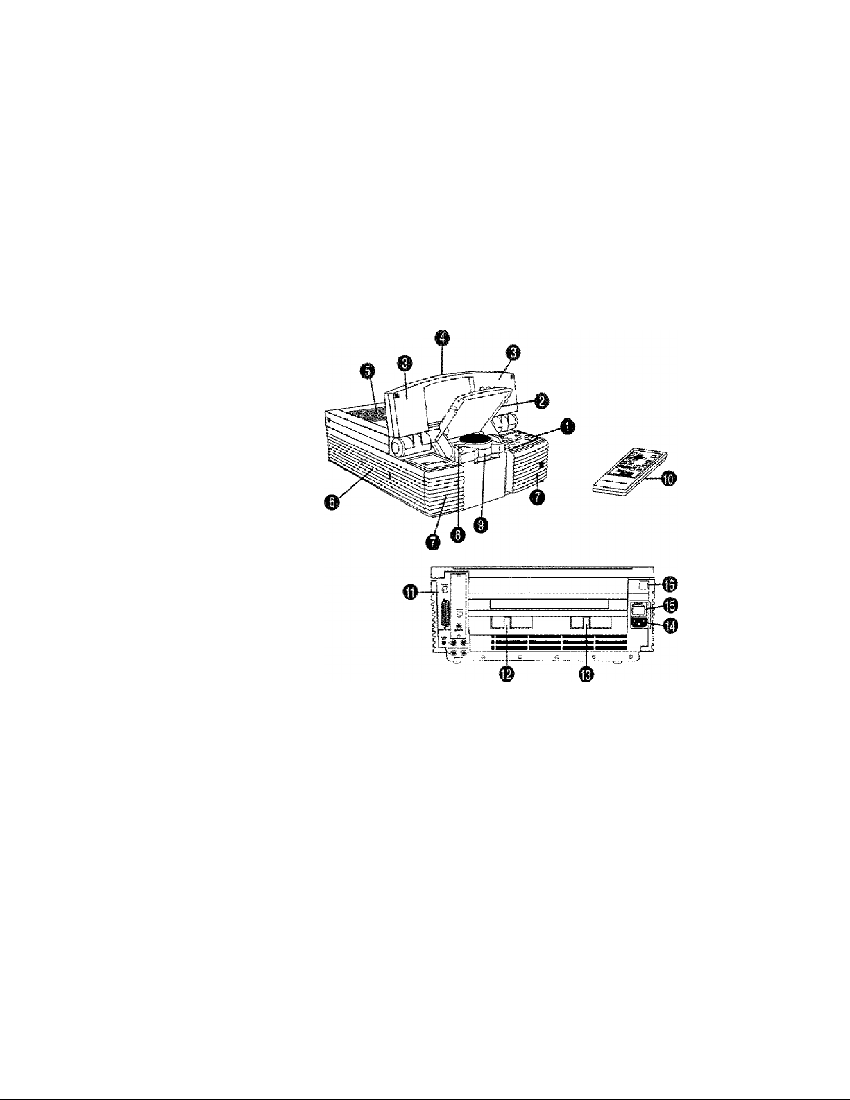
Before you begin, examine the components of the projector.
Figure 3
The Proxima Oeekcop Projector and Remote Contro!
(1) Control Panel
(2) Mirror Assembly
(3) Internal Speakers*
(4) Cover Assembly
(5) Top jAir Intake Filter
(6) Recessed Handle
(7) Front Air Intake Filters
(8) Cyclops Lens
* MpM DP2800 eni:
V
(9) Projection Lens Assembly
and Focus Ring
(10) Remote Control
(11) Connector Panel
(12) Lamp Selector
(13) Lamp Chamber Latch
(14) Power Cord Receptacle
(15) AC Power Switch
(16) Circuit Breaker Reset Button
User's Guide • 2-i
Page 17

Chapter 2 • Detailed Setup
GefctiriQ Opening the Projector
Started
I. Place the projector on a solid, flat surface. The projector
should be located at a rigiit angle (perpendicuiar) to the
projection screen and parallel to the floor.
Top View
Peopendicuter to the
projection screen
m
.0
•O
a.
O
r
8
2-P • User's Guide
Side View
Parallel to the floor
Figure
Postcioning tile Desktop Projector
<4
Note! If you’re using a media cart, make sure the wheels are
locked to prevent it from moving.
Page 18
Chapter S • Deteile-d Setup
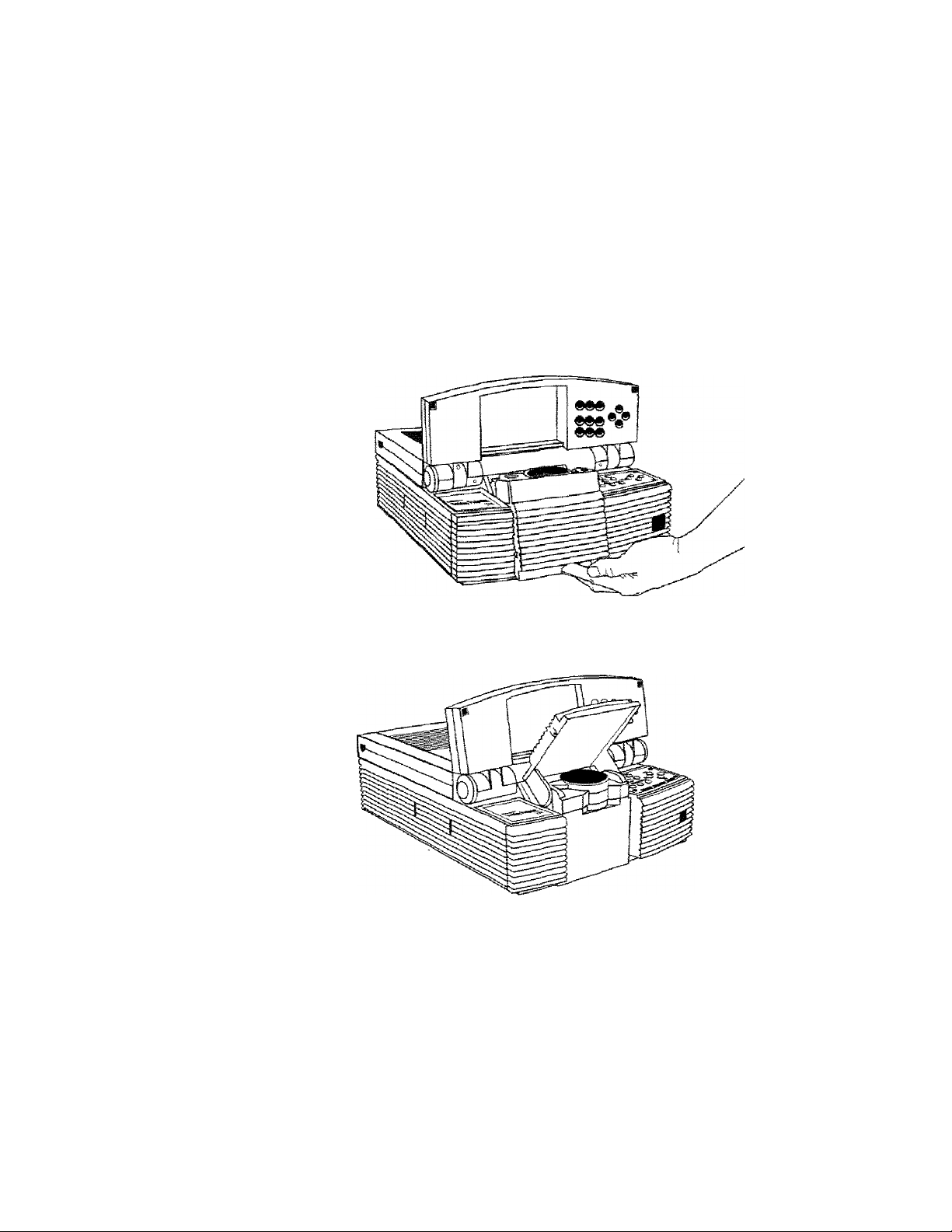
2. Grasp the front edge of the cover assembly at the upper front
of the projector. Raise it until it reaches the first stop. You can
also use the projector in the fully open position by raising the
cover assembly to the second stop.
vGGsvC-----------------------
-
:
•hi
Opaning the cowso assembly
CAUTION! The Desktop Projector's cover and projection
mirror assemblies have been designed to limit over-extension.
Applying excessive pressure can damage the pro|ector.
S
lJSer’3 CSuiclfi • 3-3
Page 19
Chapter 2 • Detailed Setup
3. Place your fingers beneath the mirror assembly (located at the
lower center of the front panel) and raise it into place until it
reaches a 45'’ angle (approximately) relative to the cop of the
lens assembly.
Figure S
Raising fche mirror assembly
User's Guide
Figure
7
The Desktop Proieotor in the open position
Your projected image should fill the projection screen. If yon
want to raise or lower the projected image, simply adjust the
mirror assembly to the appropriate angle.
Page 20
Chapter 2 • Detailed Setup
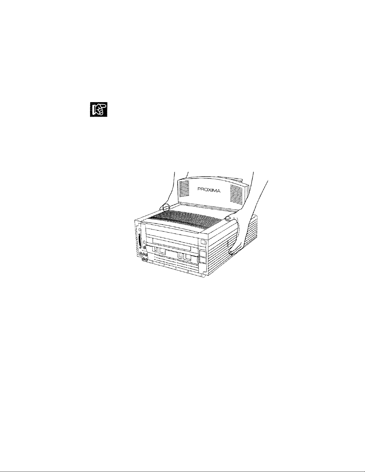
CAUTION! DO NOT attempt to lift or move the projector
hy using the assembly cover or projection mirror as a handle. IT
IS STRONGLY RECOMMENDED THAT YOU CLOSE
THE PROJECTOR COMPLETELY BEFORE MOYYNG IT!
If you must move the projector while it is open, grasp it securely
at the sides by the lower part of the housing to support the weight
of the unit.
FIsure B
Moving the proiector when open
User's Guide • 2-5
Page 21

Cfiapcer S • Detailed Setup
Using an AV Tripod
Located on the bottom of the Desktop Projector is a connector
for use with a tripod. Use only a heavy-duty, industrial audio
visual tripod that can support at least 20 pounds.
To attach the tripod to the projector:
1. Grasp the projector by the handle and stand it on its side.
2. Holding the tripod sideways, screw its threaded camera mount
into the connector on the bottom of the projector.
3. Extend and lock the tripod’s legs.
4. Grasp the projector by its handle and place your other hand
under the unit (the side opposite the handle). Lift and turn the
projector into its normal operating position on top of the
tripod.
« User’s Guide
CALiTIOIM!
Be extremely careful when using the projector
with a tripod. The foliosving precautions should be obsen,-ed:
• You can mount the projector on a tripod by yourself.
However, it is easier to do this if someone else is holding the
projector tvhiie you connect the mount.
* Make sure that the tripod legs and camera mount are
securely locked.
* Do not place the tripod and projector in any paihw'ays that
you or your audience will be using during the presentation.
• Make sure that all cables are secured and out of the way. In
particular, be extremely careful of the power cord and any
extension cords.
Page 22

Chapter S * Detaiied Setup
Closing the Projector
To close the projector, reverse the opening procedures.
1. Rotate the projection mirror assembly forward and do'«'’n until
it is in the fully closed position.
2. Rotate die hinged cover assembly forward and down ontU it is
in the fully closed position.
CAOTIOFSt!
Gently c! ose the mirror and hinged cover
assembly. Forcing them to snap into place may damage the mirror
assembly. Close the assemblies in the proper order. Do not
attempt to close the projector by only moving the cover assembly.
User’s Guide •
Page 23
Chapter 2 ^ Detailed Setup
Transporting the Projector
CAUTiOlM! Do not move or transport the Desktop Projector
without securely closing the projector and disconnecting ail of the
cables.
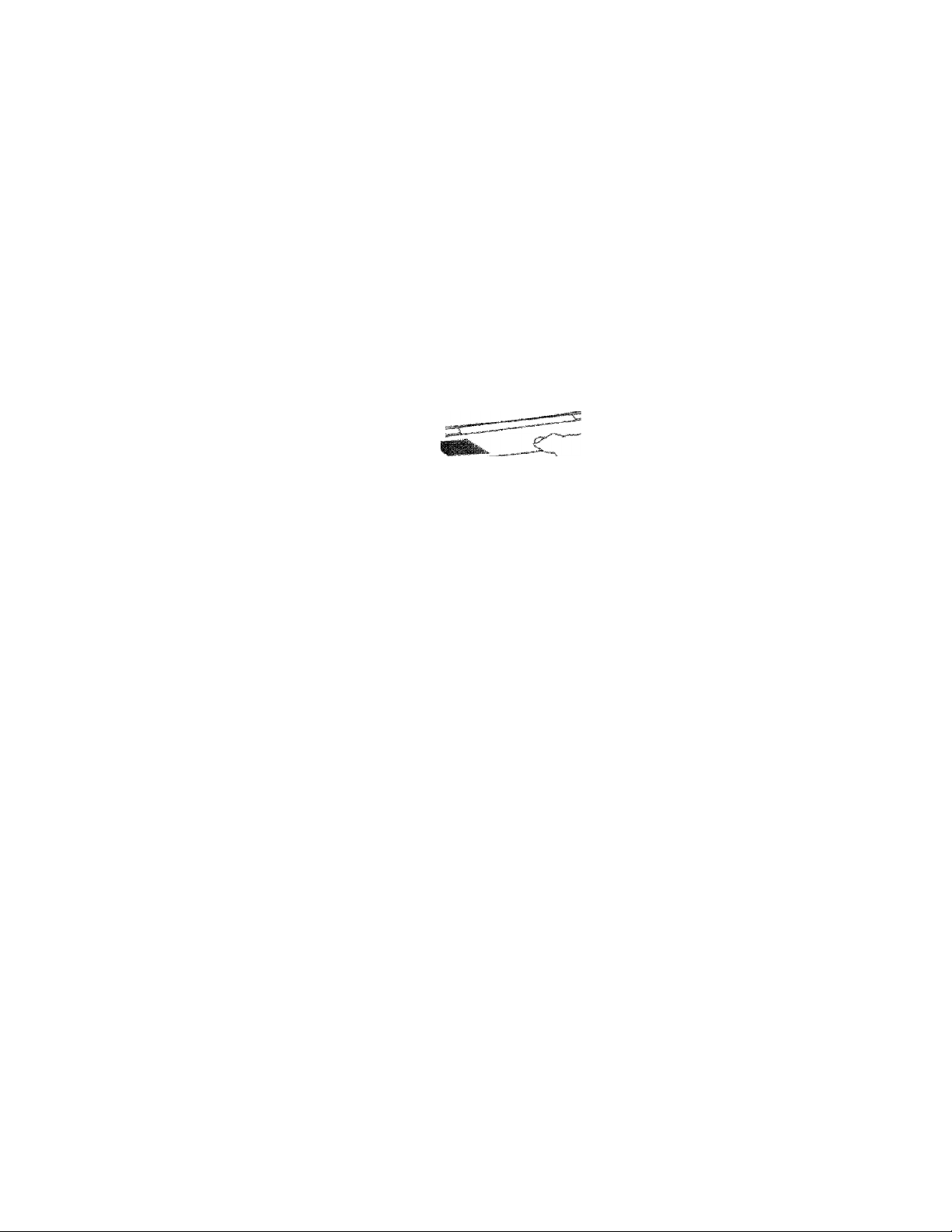
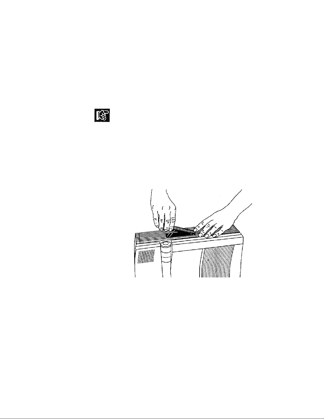
The Desktop Projector has a recessed carrying handle lo^cated in
one of the side panels.
1. Push in on either end of the handle. Pull the handle up.
2. Release the handle. The spring-loaded mechanism will retract
it back into the body of the projector.
2-B » User’s Guide
Figure S
Accessing the handle
IMote; The projector has protective feet on the side opposite the
handle as well as on the bottom.
Page 24
Chapter 2 • Detailed Setup
Connecfclng
the Desktop
Projector
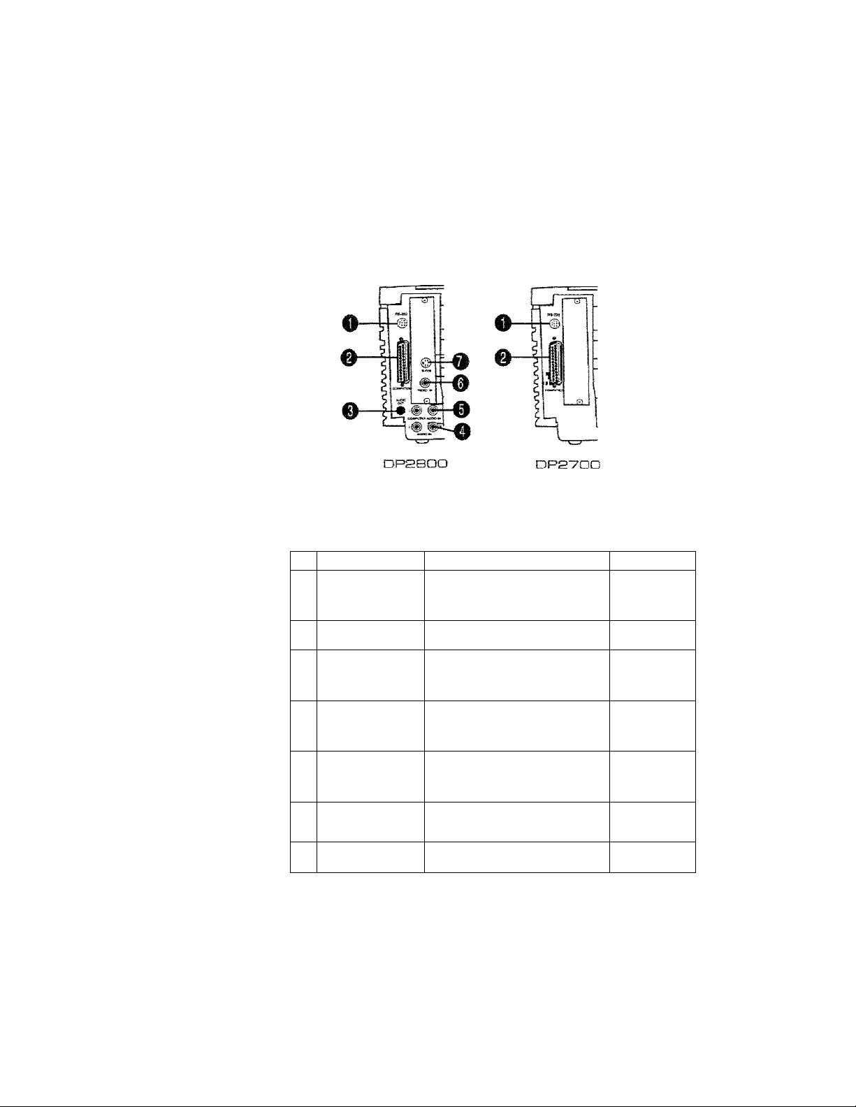
Take a moment to look at the projector's rear connector panel,
Figure TO
The Conoecfcor Panels
Connector Cb3 Oescription
1 HS-a32
COMPUTER
2
AUDIO OUT
3
AUDIO IN Left and right inputs
A
5 COMPUTER
AUDIO IN
B VIDEO IN NTSC/PAL/SECAM input
S-VHS
T
■ Requires ap transí vtdea adapter ipart: numt>er A1 35)
For using optional
Cyclops system or
Presentation Control
SoftAware
Connects computer
video to the proiecton
Stereo output to
eKternel powered
speakers or external
sound system
from VCP or other audio
source, or amplified or
wireless microphone
Left and right inputs
from computer audio
source, or amplified or
wireless microphone
from VCRs, laserdisc
piayers, and camcorders
Input from S-VHS or
S-video source
ModelCs}
DPSBDO
DP270D
DPaSOQ
DPPTOO
DPPBOO
DP2SGO
DPPSOO
DP2BOO
DP3TOO»
DPasoo
DPaToo"
User's Guide
2-3
Page 25
Chapter 2 » Detailed Setup
COMPUTER
The video Y-cab!e allows you to connect your computer to both
the Desktop Projector and to a separate computer monitor so that
you can view computer video output on the monitor and
projection screen simultaneously.
Desktop Computers
if you are using a desktop computer, regardless of whether it’s an
IBM compatible or a Macintosh system, the sequence for
connecting it to your Desktop Projector is exactly the same. Use
the Y-cablc appropriate to your system. For IBM compatibles, use
part number C454-6; for Macintosh systems, use part number
C464-6.
2-10 • User's Guide
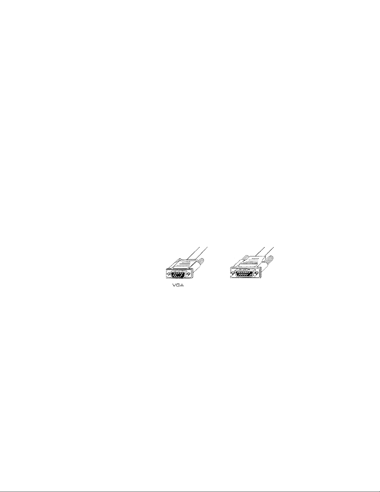
tvjBcintosh
Figure T i
VGA and Macintosh connectors
1. Turn off all power to your computer, its monitor, and the
Desktop Projector.
2. Unplug your monitor cable from your computer’s video
monitor port and attach the cable to the short end of the
Y-cable (marked MONITOR).
3. Locate the Y-cabie's common end, marked CPU/MAC II for
Macintosh systems and COMPUTER/VGA for IBM—
compatibles. Plug it into the computer's monitor port.
Page 26

Chapter 2 • Detailed Setup
4. Insert die Y-cabk’s iarge> 25-pin connector (marked LCD)
into the Desktop Projector's COMPUTER port.
Figure “1S
VGA connections
Figure i3
Macintosh connections
User’s Guide • 2-11
Page 27

Chapter S • Decsited Setup
Notes
If )roii wane to use your desktop computer without a
monitor, connect one of the supplied video terminators to the
short end of the Y-cable (marked MONITOR). Use the
appropriate terminator for your system. For IBM compatibles, use
part number C936; for Macintosh systems, use part number
C935.
Notebooks/Laptaps
Use the Y-cabJc appropriate to your system. For IBM
compatibles, use part number C454-6; for Macintosh systems, use
part number C464-6.
1. Turn off ail power to your notebook or laptop computer and
the Desktop Projector.
2. Locate the Y-cable's common end, marked CPU/MAC II for
Macintosh systems or COM PUTER/VGA for IBM
compatibles. Plug it into the computer’s monitor port.
3. Insert the Y-cab!e’s large, 25--pin connector (marked LCD)
into the Desktop Projector’s COMPUTER port.
2-i 0 • User’s Guide
4. Attach the appropriate video terminator to the short end of the
Y-cable (marked MONITOR). For IBM compatibles, use part
number C936; for Macintosh systems, use part number C935-
Not:e: If you don’t get an image (i.e., your Desktop Projector is
unable to project an image at the same time that your laptop
computer displays a screen image), refer to your computer's
reference materials for information on how to switch between the
internal screen and the video port.
Page 28

Chapter 2 Detailed Setup
IMat:eii
If you're using your notebook or laptop computer with
an external monitor, follow the procedure described in the
previous section tided Desktop Computers.
Special Configurations
If your computer has an internal monitor but does not have
external video capabilities (i.e., Macintosh SEs and certain
PowerBooks), you will need a video adapter card in order to
attach the Desktop Projector. Setup for a third-party adapter is
identical to the procedures outlined in the previous section titled
Desktop Computers. Contact your dealer, Proxima Customer
Ser\^ice, or a third-party' supplier for more information regarding
video adapters.
RS-232
The RS—232 port allows you to use the optional Cyclops
interactive pointer system or the Proxima Presentation Control
Software. Instructions for connecting the appropriate serial or
ADB cables are included with each of these products.
User’s Guide
2-1 3
Page 29

Chapcer 2 • Det;ai!sd Setup
VIDEO IN
The Desktop Projector 2800 can project video from NTSC, PAL
or SECAM sources (i.e.,VCRs, laserdisc players and camcorders).
2-1-*4 ♦ User’s Guide
Figure 'I <4
The Desktop Projector connected to a video source
To connect an NTSC, PAL, or SECAM source to your Desktop
Projector:
1, The composite audio/video cable (part number C497-6) is
made up of 3 cables with ydlow, red, and white RCA plugs.
Insert the yellow RCA plug into the circular connector on your
camcorder, laserdisc player, or VCR marked VIDEO OUT,
TO MONITOR, or something similar.
2, Insert the other yellow RCA plug into the projector s \dDEO
IN port.
The red and white cables are for audio^ input from the video
source. Refer to the AUDIO AVsection later in this chapter.
Page 30

Chapter S • Detsited Setup
With the installation of an optional video adapter (part niimber
A195), the Model DP2700 can also display video images from an
NTSC, PAL or SECAiv4 source. Refer to Appendix B: Accessories
dr Replacement Parts for ordering information.
S-VHS
The Desktop Projector 2800 can project video from an
S—VHS or S—Video source.
1. Connect one end of the S-Video (Y-C) cable (part number
C466-6) to your video source connector marked VIDEO
OUT, TO MONITOR, or something similar. The cable has
identical round 4-pin connectors on either end,
2. Connect the other end of the cable to the Desktop Projector's
input connector marked S-VHS.
With the installation of an optional video adapter (part number
A195), the Model DP2700 can also display video images from an
S~\''HS or S-Video source. Refer to Appendix B: Accessories dr
Replacement Parts for ordering information.
User's Guide * S-1 5
Page 31

Chapter 2 • Detaiied Setup
COMPUTER AUDIO IN
The COMPUTER AUDIO IN connector allows rhe Model
DP2800 to receive audio input from a computer or a
microphone.
Connecting Youn Computer’s Audio
1. Insert the mini jack end of the computer audio cable (part
number C498-6) into the AUDIO OUT connector of a
Macintosh or the sound card of an IBM compatible.
2. Insert the RCA jacks at the other end of the computer audio
cable into the projector’s left and right COMPUTER AUDIO
IN connectors.
AUDIO IN
2-16 • User’s Euide
The Model DP2800 has left and right stereo connectors for audio
input from VCRs, laserdisc players, and other video equipment.
Connecting
a
Video Audio Source
The composite audio/video cable (part number C497-6) is made
up of 3 cables with yellow, red, and white RCA plugs,
1, Insert a white RCA plug into your video source’s left AUDIO
OUT connector. Insert the other white RCA plug into the
projector’s left AUDIO IN port.
Page 32

Chapter 2 ♦ Defcailed Setup
2. Insert a red RCA plug into your video source’s right AUDIO
OUTconnector. Insert the other red RCA plug into the
projector’s right AUDIO IN port.
Mote;
Although both COMPUTER AUDIO IN and AUDIO
IN may be connected simultaneously^ only one is active.
* If computer video is selected, COMPUTER AUDIO IN is
active.
• If NTSC/PALiSECAM/S-VHS video is being viewed,
AUDIO IN is active.
Connecting a Monaural Source
If you have a monaural source that you want to play through the
Desktop Projector’s left and right speakers, use the RCA “Y”
adapter cable (part number C496) to connect the source to the
projector’s left and right AUDIO IN connecrors. If you are using
computer audio, connect the source to the projector’s Left and
Right COMPUTER AUDIO IN connectors.
User's Guide • 3-17
Page 33

Chapter £2 • OataiSed Setup
Connecting a Microphone
When you need to address a larger audience while projecting an
NTSC; PAL, SECAM or S-LTiS video image, plug an amplified
or warcless microphone equipped with a line level output
(maximum level of 1 vok, peak-to-peak) into the Left and Right
AUDIO IN connectors. The microphone wHi work when an
NTSC, PAL, SECAM or S ATiS video image is proiected. If you
wish to address a larger audience while projecting a computer
image, connect the source to the projector s Left and Right
COMPUTER AUDIO IN connectors.
If your microphone s amplifier has only one output, use the RCA
“Y” adapter cable (part number C496) and a standard RCA cable
to connect it to both of the projectors AUDIO IN or
COMPUTER AUDIO IN connectors.
AUDIO OUT
2-1G • Usan's Guide
The Model DP2800 contains an internal stereo system consisting
of an amplifier and two speakers. Although this system provides
high qualit}" stereo output, a multimedia presentation may require
connecting the projector to external powered speakers or an
external sound system.
Page 34

Chapter S • Detailed Setup
External Speakers
''JC^en connecting external speakers> use the optional Proxima
Powered Loudspeaker System (part number A55) or a similar
system. References in the following procedure are to Figure 15.
To connect your Desktop Projector to external powered speakers:
1. Insert the mini plug of the stereo cable (supplied with your
powered speakers) into the projector's AUDIO OUT port.
2. Insert the other end of the cable into speaker A.
3. Connect speaker A to speaker B using the cables supplied with
the speaker system.
Figure 15
Connecting the Desktop Projector to externai speakers
User's Guide • 2-10
Page 35

Chspcer 3. • Decailed Setup
Externa! Stereo System
To connect your Desktop Projector to an external stereo system;
1. Using the computer audio cable (part number C498—6), insert
the mini jack end into the Model DP2800’s AUDIO OUT
port.
2. Insert the RCA connectors at the other end of the cable into
the external amplifier’s left and right AUDIO IN ports.
2~SD • User’s Guide
Figure IS
Connecting ehe Desktop Pnojeccor' to an externai stereo
system
Page 36

Chapter E? • Detailed Setup
Powering Up Your Desktop Projector and external monitor (if you are using
one) must be powered-up before turning on your computer, so
that your computer properly senses each display during its boot
up sequence.
Appiying Power to the Projector
On the rear connector pane! of the projector, you'll find a power
cord receptacle and an AC POWER switch.
....
......
''"'I
.....
iniD^
■P5
Figure T7
Power receptacle C13, AC POWER switch CS), and circuit
breaker reset switch [33
To power up the projector:
I. Plug the power cord into the Desktop Projector's power
receptacle at the rear of the unit,
CAUTIOISi! Plug the AC power cord into the Desktop
Projeaor BEFORE connecting it to an electrical outlet. If you
plug the power cord into the wail first, it might damage the
projector.
User’s Guide •
Page 37

tcäpcer- bi • Detailed Setup
2. Connect the power cord to a properiy-grounded wall otitiet,
3. Move the AC POWER switch to the ON position. The
projector’s fan wi!t begin to run. If you do not hear the fan,
refer to Chapter s, TroiMeshoming.
4. Turn on your monitor and com|}uter.
CAUTIO^r^! Locate the air intake and exhaust grills on the top
сол?ег and to the left and right sides of the projection mirror
assembly, and the exhaust grills on the rear panel and side of the
projector. Never operate the projector if these grills are dogged or
obstructed, or if the electric fans are no t running.
Э-ЭЭ • User’e Guide
Figur® 'IS
Allow for proper sir flow!
CAUTIOIMi The lamp chamber gets Ycrg hot during
operation, in particular, the ceramic socket at the lamps base can
get extremely hod Use appropriate care when open.irig the lamp
chamber or changing lamps. Make sure that the lamp chamber
and lamp have cooled for at kast 6 minutes with the fan ranning.
To do so, press the LAMP button ro turn off the lamp and allow
the fan operate for several minutes.
Page 38

Chapter 2 * Datai ied Setup
ISiotie:
If you turn the Desktop Projector off while the rest of
your computer system is running, your external monitor will go
blank. This is norma!. Just turn the Desktop Projector on again
and your monitor display will return.
Turning On/Off the Lemp
When you first turn on the projector, the lamp will be on. To
turn the Desktop Projector’s lamp off, press the LAMP key on the
Control Panel or remote control. Pressing the LAMP key again
will turn the lamp on. The lamp turns on slowly to prolong lamp
life.
Figur® *19
The LAMP key
jjKTH IMcrfce: Turning the lamp off does not cut power to the
projector. The fans will still operate. You must moYe the AC
POWER switch to the OFF position to completely power down
the projector.
User's eSutde • 2--23
Page 39

I iapt;er* y • Oecsiled Setup
Prolectlng Your next step is ro adjust the projected image for size and clarittt
the
image
image Size
The size of the projected image varies according to the distance
from the Desktop Projector to the projection screen. The
following table shows the projected image size (measured
diagonally) based on the distance from the projector to the screen.
- ^ OS
Oii>TVl
- X OS
Dfst-enee
from
Screen
4 ft/1 ,2 m
B ftZ1
.a
m
S
fxJS.A
m
10 ft/3,0 m
1
2
ft/3,e m ; lOS.7"/a78.B cm
14
ftJA.3
m
Oisgonal Image Sl*e
35"/a8-9 cm
53.5'yi35.S
ZS'y 182.0 cm
3O,5*’/ees.0 cm i
las'ysas.i
cm
cm
W'
12B"/3S5,1 cm
Figure ao
Diagonal meaeur^menc of projeetjeei image when Desktop
Projector is 14' i*a.3 mJ from projecEtort screen
ftATtO ,
2-24 • User's Guide
Page 40

Chapter 2 • Detaiteci Setup
Focusing
You can use the title screen image that appears when you first
start up the projector to make your adjustments.
Using a thumb or fingertip, rotate the focus ring to the right or
left for the dearest displayed Image.
The
pnoiecton lens focus
ring
User's Guide • 2-35
Page 41

t_jei;aMed Setup
Keystoning
Tlie normal projected image will have a rectangular shape.
Keystoning is when the projecrcci image becomes trapezoidal.
800
800
400
200
0
Mil
Mm I KAY i juM m
Norme) Image
Fj0Mr-® ea
fStorme
\
‘tTssI vs. keysconecJ images
Keyscooed Image
Keystoning occurs when the front of the Desktop Projector is not
perpendicular to the projection screen (the vertical plane) or when
it’s not placed parallel to the floor (the horizontal plane}.
Keystoning also occurs when the Desktop Projector is tilted
sidew^ays.
•
User's Guide
Page 42

Chapter 2 • Detailed Setup
To correct for keystoning, always make sure that the projector is
at a right angle to the screen in the horizontal plane. The
projector is properly aligned if the top and bottom of the
projected image are equal in length and parallel to the floor.
Figure
Pasi-tioning the Desktop Projector
In order to allow you to project images high enough for the entire
audience to view, the Desktop Projector has been designed to
minimize this effect. A 10.5° correction for keystoning is built
into the projector.
+ vi
User’s Guide » 2-27
(.kt
Page 43

Chapter 3
Using the
Desktop
Projector
The
Control
This chapter provides detailed information on the Desktop
Projector settings, the Control Panel functions, the Menu
Windows, and the warning indicators.
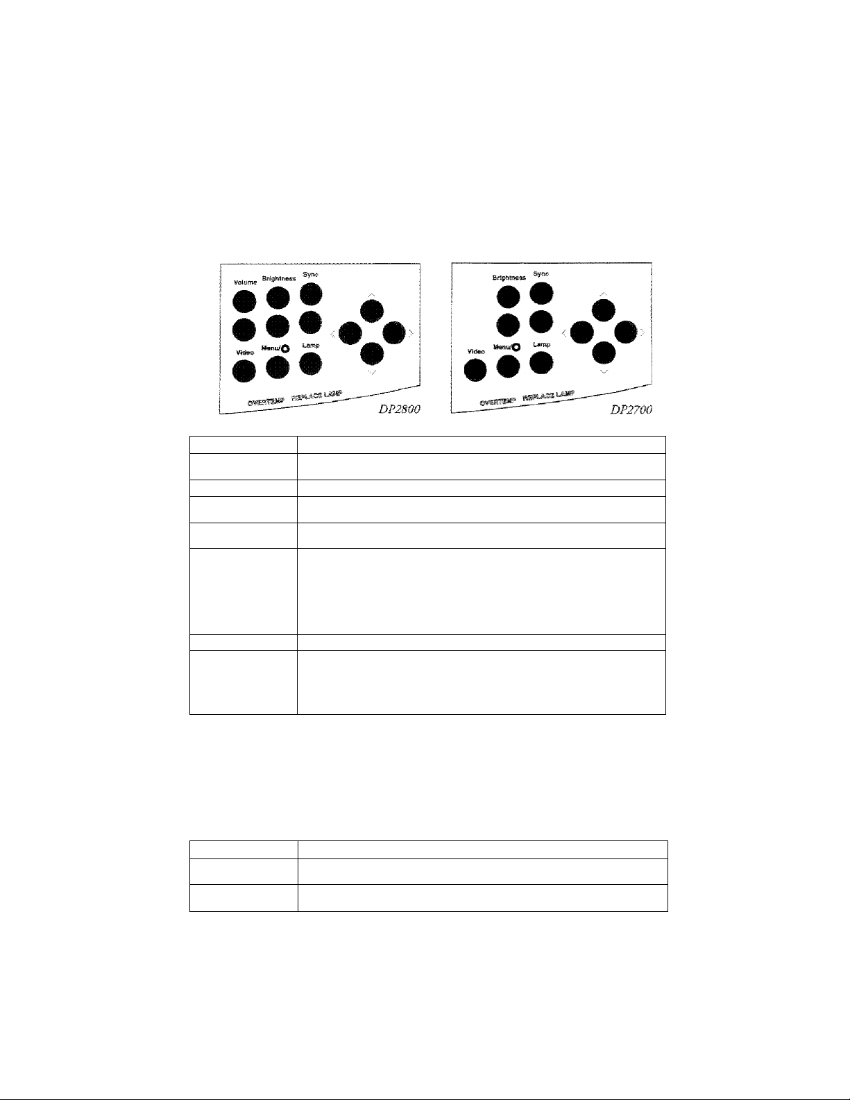
The following figure shows the control panel configurations for
Panel the Model DP2800 and the Model DP2700.
Sync
Model DP2SOO
Mode! DPST^QO
Figure B«!
Model DPEBDO and Model DP2700 cantroi panels
Brightness
Menu/Q tsrttp
User's Guide • 3-1
Page 44

• Using fche Desktop Pnojecfeor
The Control Arrow Keys
Panel Keys
------------------------
The four arrow keys allow you to;
• Make small adjustments to the projected image's position
on the screen. Pressing an arrow key shifts the projected
image in the direction indicated by the arrow, or
• Access and modii}' settings within the Menu windows.
For more information, please refer to the section titled The Menu
Settings later in this chapter.
BRIGHTNESS Keys
The BRIGHTNESS keys increase and decrease the intensity level
of the projected image. Press the top key to increase brightness
and the bottom key to decrease it.
3-2 • User's Guide
LAMP Key
The LAMP key toggles the projection lamp on and olE
• if you turn the lamp off but leave the projector on, the fan
will continue ro run,
• You can turn the projector off without allowing the fan to
cool down rhe unit. However, the projector will take a little
longer to cool.
Page 45

Chapter 3 • Using the Desktop Projector
MENU/@ (CYCLOPS) Key
This key allows you to access and modify the current Desktop
Projector settings in the Menu Window, which appears in the
lower portion of the displayed image. This key also allows you to
initiate the light measurement sequence for calibrating the
optional Cyclops interactive pointer system (part number A2060)
and to disable Cyclops when you wish to use Proxima's
Presentation Control Sofiw'are.
1. Press the MENU key to display the Levels Menu.
2. Press the MENU key again to display the Setup Menu.
3. Exit the Menu Window by pressing the MENU key a third
time.
For more information, please refer to the section titled The Menu
Settings later in this chapter.
No1:e: Pressing the MENU key twice in rapid succession will
allow you to:
• Access the Menu Window and go directly to the Setup
Menu, or
• Exit the Menu Windosv from the Levels Menu.
Mates Holding the MENU key down for several seconds
initiates the Cyclops light measurement sequence. For more
information, please refer to your Cychps User’s Guide.
€>
User’s Guide • 3-3
Page 46

Chapter 3 • Using the Desktop Projector
Pslote:
You cannot use Cyclops and Proxima’s Presentation
Control Software at the same time. To disable Cyclops and use
the software, hold the MENU key on the Control Panel down
when you turn tire projector power on. This procedure will not
work with the remote control. To re-enable Cyclops, turn the
projector off and then power it up again.
SYNC Keys
The SYNC keys ate used to compensate for fine variations in the
riming of a computer's video signal. Sync is only used with
computer video. Adjust this setting if you see uneven horizontal
fearures, streaks or shimmering in a graphics image. Press the
upper or lower SYNC key until the image stabilizes.
VIDEO Key
The VIDEO key on the Model DP2800 is used to switch
betw'een computer video input, NTSC/PAL/SECAM video input,
or S-VHS input.
Nolbe!
The VIDEO key on the Model DP2700 is operational
only if the optional video adapter (parr number Al 95) is installed,
3-4 • User’s Guide
VOLUME Keys
The VOLUME keys on the Control Panel are used to adjust the
audio level of the Model DP2800’s internal speakers. Press the Up
or Down key to increase or decrease the speakers’ audio level.
Page 47

Chapter 3 • Using the Desktop “Projector
The Menu The Menu Window appears in the lower portion of the projected
Settings image, displaying the currently selected settings for the Desktop
Projector,
1. Press the MENU key on the Control Panel or the remote
control to display the Levels Menu.
2, Press the MENU key a second time to display the Setup
Menu.
Selecting and Changing Settings
To move to and change a setting;
1. Use the Right or Left arrow' key to move to the setting that
you v/ish to change.
2, Use the Up or Down arrow key to change the setting.
I\iat;e: The active setting (the one that you can change) is
indicated by a red outline.
Saving Changes
To save any modifications you make to the projector settings;
1. Access the Setup Menu.
2. Use the Right or Left arrow key to move to the STORE
setting.
3. Use the Up or Down arrow key to choose the STORING
option.
User's Guide • 3-5
Page 48

tjaapter 3 • Using che Desktop Projector
Levels Menu
Press the MENU key once to display the Levels Menu. From
here, you can change the levels for the profecior s image and audio
controls. The menus vary automatically based on the type of video
source displayed.
BRÌ6HTNESS
ffiHUL
SYNC
cm;
GREEN
rrrm
□
volume
iiwwm
BLUE
iilimr"
Mcciei opaecjo
BRiGHTNtSS SYNC
IIMMI !
RED., GREEM
muzzi
ivsadas DPS700
Fisure ss
Levate Menu for computer video
BRIGHTNESS
R
nuni
fwiodel DPSSOO
■nwr i
CONTRAS!
lWiMr~
lilfHi 1
VOLUME
3~6 « User's Guide
BRiC-HTL-ESS R
ilMMMl I r
CONTRAS!
■ nm
fvSoOet OPEVOD
Fiaurw ae
Level® Menu for NTSC/PADSECAM end S-VHS video
BRIGHTNESS
This control is used to increase and decrease the im^c brightness
level. It functions the same way as the BRIGHTNESS key on the
Control Panel. Use the Up or Down arrow key to increase or
decrease the brightness level.
Page 49

Chapter 3 ♦ Using the Desktop Proiector
SYNC
Adjust this setting if 70U see uneven horizontal features, streaks or
shimmering in a computer video image. Press the Up or Down
arrow key until the image stabilizes.
VOLUME
This selection is used to adjust the volume level if an audio device
is connected to the DP2800, Use the Up or Down arrowr key to
increase or decrease the volume le\'d.
Not:e;
For optimal sound control when using an external
amplifier (i.e., stereo system), preset the VOLUME setting to
50% {5 bars) before adjusting the volume on the amplifier to a
comfortable listening level.
RGB Controls: RED, GREEN & BLUE
The RED, GREEN and BLUE controls can be used to
individually adjust the color signals. Use the Up or Down arrow
key to increase or decrease the color signal level. These settings are
simultaneously increased or decreased when the BRIGHTNESS
control is adjusted.
TINT
The TINT setting (R and G) adjusts the Red or Green color
balance for NTSC/PAL/SECAM video or S-video sources. It has
no effect in other video modes. Use the Up or Down arrow key to
adjust the color signal balance.
User's Guide • 3-7
Page 50

Chapter 3 • Using the Desktop Projector
CONTRAST
The CONTRAST setting is used by the Model DP2800 for
NTSC/PAL/SECAiM or S-VHS video. Use the Up or Down
arrow key to adjust the contrast in the projected image.
CONTRAST is available for the Model DP2700 if it has been
upgraded for video.
Setcup Menu
To access the Setup Menu:
Push the MENU key to access the Levels Menu. Press the
MENU key again to access the Setup Menu, or
Press the MENU kejf twice to skip the first window and go
directly to the Setup Menu.
SOURCE iriAGE
(VGA640x4g0| r~lTlTtAr
FREQUENCY LAM3UAGE
~~8Q0 1 ( ENCIjuT"
Pigitre S7
Setup
Menu
COLORS PROJECTION
~2269§T~| rTORW^Dl
STORE?
NO
SETTINGS
r ACTORV
3-S * User's Guide
Page 51

Chapter 3 • Using the Desktop Projector
SOURCE
SOURCE doubles as both a status and selection box. When you
connect a video input, this setting lists the name of the input
source detected by the projector.
If the Model DP2800 detects an NTSC source, it automatically
defaults to it. The projector cannot tell the difference between
PAL or SECAM. ''XTien P,AL or SECAM is used, the Desktop
Projector defaults to PAL. The SOURCE setting allows you to
select SECAM as the video source input.
The Desktop Projector selects the best possible value based on the
incoming signal. If the image doesn’t look right {i.e., wrong
colors, image is off screen, image won’t sync properly), use the Up
or Dowm arrow key to make an alternate selection.
The Mode! DP2800 can store a full set of values for each video
mode, allowing you to switch back and forth between video
inputs and retain your adjusted settings. Upon startup, the
projector automatically returns to the last-stored entries for each
video mode.
IMAGE
This control allows you to switch between NORMAL and
RETTiRSE video modes. REVERSE is used primarily for view'ing
text screens.
User's Guide • 3-S
Page 52

Chapeen 3 • Using the Desktop Projector
COLORS
This setting allows you to select the color mode most suitable for
the t)'pe of image you’re projecting. Use the Up or Down arrow
key to cycle through the choices.
Oolor
Mode
S
3,37a
s^B.aai
*
S.M* For NTSC,
Oescripclon Primary Ue©
TypicaiisJ resulta
in lower color
resoiutior fauC
brighter image
Best for
VGA/MBcintosh
business
graphics or
other
applications
requiring bright,
high contrast
colors
Best
for
computer
graphics
VHS Video
complex
Afvl or S
PAL,
.
SEC
in E€SA/OGA/K^OA/Herx:^'ijl&is
Text screens
Computer video
Graphics, animation or
NTSO/PALyseCAM/S-VHS
NTSCyPAUSECA(Vi/S-VHS
compuceu
s/iúeo
rr?oa’®.
PROJECTION
This function can be used to flip the displayed image, allowing
the Desktop Projector to be used with a rear projection screen.
PROJECTION can be used in all video modes. Use the Up or
Down arrow key to cycle berwceii the FORWARD and REAR
options.
3-1 Q User's Guide
Page 53

Chepcer 3 * Using the Desktop Pi'otector
FREQUENCY
This adjustnient allows you to synchroiiiEc the Desktop Projector
ss'ith your \-ideo source. For example, if your computer has a video
card with non-standard signal components (i.e., h-sync or v-sync),
the projected image may look jittery, contain bands, or appear
out-of-focus. Use the Up or Down arrow key until you find the
setting that projects the best im.age.
IMote: Always adjust SYNC before changing the
FREQUENCY setting.
LANGUAGE
LANGUAGE allows you to select a particular language set for the
Menu 'Window, Languages displayed include English, German,
Italian, French and Spanis-h. Use the Up or Down arrow key to
c)'cie through
the choices.
STORE?
This function allows you to save the settings currendy displayed
in both Menus. The saved settings will be used until you define
new settings, or rertira to the fa.ctoiy*-configured defaults.
YUten you store ricss^ settings, they overwrite any values pret'iously
defined for that particular mode. Stored settings are retained even
after the projector is turned off.
Lieen's Guide » 3-11
Page 54

cjsing the Desktop Projector
SETTINGS
This function allocsrs you to retrieve the factory-set or stored
settings for the current emry displayed in the SOURCE field. Use
the Up or Down arrow key to cycle through the options.
* FACTORY - RecaJls the dcfauii factor)*—configured values.
These will be used until you define new settings.
* STORED - Recalls your last saved settings for the current
video source,
* CURRENT — indicates that changes have been made, are in
use, and have not yet been saved.
Factory Defaults
The first time you turn the Desktop Projector on, factory-set
operating values are used. These default settings remain the same
over the life of the system. If you change any of these settings, you
can recall the factory defaults by accessing the SETTINGS
funedon and choosing FAGFORY.
3-1 a • User's Guide
Page 55

Chspten 3 * Using the Desktop Projeotop
Warning and
Alert Lights
Warning and alerr lights located on the projector s control panel
provide you with an indication of the Desktop Projector’s
operating condition.
Brightness
Votum«
FI gu-re. HS
Warning lights
OVERTEMP Warning Light
Sync
Lanri^p
The OVERTEMP warning will light in the unlikely event that
the projector reaches an over-temperature condition. A
thermostat will switch off lamp power until the projector cools.
CAUTiOhli DO NOT TURN OFF THE PROJECTOR!
The power must be left on so the fans can cool down the unit.
User's Guide • 3-13
Page 56

ijnapter 3 • Using the Desktop Projector
H a.n OVERTEMP condition occurs, perform tire foiiowing
checks %%Tiie you aliow the projector to cool:
After the projector returns to its normal operating temperature,
the OVERTEMP warning light will go out, in order to- turn the
lamp hack on again, you must press the LAMP key on the
Control Panel or remote control,.
* Verify that the room temperature is below 80® F (27* C).
♦ Check the intaJte griUs and exhaust vents. Clear any
obstruction to the air flow,
• Check the filter elements. Clean or replace them if
necessar)'. For more information, please refer to Chapter 4,
Maintenance.
• Check the rear and side exhaust vents. If the projector has
reached an OhTRTEMP condition and the fans are
working, you should feel a strong rush of hot air from the
vents. If the fans are not ’working, the Desktop Projector
needs service.
3-1A • User’s Guide
IMotes The remote сомгоГ$ LAhiP key will not function, after
an OVERTEMP condition u.nt.O the lamp is turned on from the
Control Panel.
REPLACE LAMP Alert Light
The REPLACE LAAfP alert light will illuminate if the active
and/or alternate projection lamps have- burned out, or if the lamp
seieccor is not fully engaged.
You can continue your presentation if one lamp has burned out.
REPLACE LAMP remains on as a reminder to replace the burned
out lamp.
Page 57

Chapter 3 • Using the Desktop Projector
Remote The remote control contains all the key ftmciions available on the
Contro! Control Panel
VIDEO
CZI Q
- SYNC +
□ iZD
* BiilGKFNESS *
• yOllif-tE *
CZ] □
fjmj
CD
craops
TDCr
CD
cz: cm
B'iH MUTE
“ CD
^ I
Desktop PHliiiff.
2700 and 2800
keys K PCiMAC pfemois
Figure
Remotie oontnoi unit;
Note: Unlike the MENU/^ key on the Control Panci, the isr
remote control’s MENU/CYCLOPS key cannot be used to ^ \ ^
disable Cyclops. ^ 'C
IMote: For best results, always aim the remote at the projection
screen or at the projector s front edge. Never obstruct the red
infrared receiver eye located beneath the Control Panel.
b
The remote control also provides access to additional functions
not available on the Control Panel or through the Menu
windows.
User's Guide • 3-1 5
Page 58

1 ty one ueskt,op Projector
MUTE Key
This key is used to momentarily shut down audio output from
the Mode] DP2800. Pressing the MUTE key again toggles the
sound back on.
TEXT Key
The TEXT key toggles berweers the Graphics mode of 640 x 480
lines and the Text mode of 720 x 400 lines. A DOS text screen is
easier to view when in Text mode.
REV, PAUSE and
FWD
Keys
These three control keys w^ork with Proxima’s MacRemote and
PCRemote Preseiitation Control Software, which can be used to
sequence ekctrorsic slides.
For
more information, please refer to
the Preiemation Control Software Guide that comes with your
so.ftware.
3-1 B • User’s Guide
Page 59

Chapter *4
Maintenance
There is ver^'" little involved with the care and maintenance of
your Desktop Projector. However, common sense and periodic
maintenance will ensure top performance.
An optional maintenance kit (parr number A60) is available that
includes the following materials:
• (2) Halogen lamps
• Lens cleaning fluid
• Lens tissue
• Top and front air filters
• Can of compressed air
The lamps, lenses, mirrors, and LCD panel have been carefully
aligned at the factory to give you the dearest, brightest image
possible. Howe\'er, physical abuse can cause misalignment or
damage to the optical elements. Take appropriate care in use and
handling.
CAtJTiOfM! The Desktop Projector contains sensitive
circuitry and optics. Protect it from potential fluid spills.
User's Guide • «A-i
Page 60

Chaptser ^ • fVleintien-anc:::^
Cleaning From time to time, you’ll need to clean the optics on the lens and
mirror assembiy.
Projection Lens on Minron
1. Take a piece of lens tissue and form it into a loose swab. Wet
2. Take another part of the lens tissue not touched by your bare
fingers and repeat the process, going over the lens or mirror in
another direction.
3. Repeat steps 1 and 2 until no smudges or particles сад be seen
when the lens or mirror is illuminated by a strong light. If the
lens or mirror is extremely Ьягу', it шау be necessary to use
several pieces of lens tissue. Water may be used if alcohol is
unavailable.
it w'ith lens cleaning fluid or alcohol and gently move it over
the
lens or mirror surface.
A~'2.
• User’s Guide
CALJTtOIM! Acetone should NEVER be used because it may
remove the paint from the metal lens or mirror mount and leave a
residue on the glass surface.
Page 61

Chapter 4 * Maintenance
General
Maintienance
I
S . iCp3
Switching Lamps
If your projector lamp burns out during a presentation, the
LAMP SELECTOR switch allows you to quickly and easily
change to a backup lamp.
Figura 30
The iemp eeiecbor
You do not have to turn off projector power before switching
lamps. As you move the LAMP SELECTOR switch to its
opposite position, you’ll feel the switch click into place. The
alternate lamp will illuminate, coming to full brightness slowly to
extend the life of the lamp.
User's Guide • ■4-3
Page 62

Ghspcer A • Maintenance
Replacing Lamps
ixave tiie Desktop Projector running with the lamp ejf prior to
changing: lamps. This will allow the fan to run and speed the
cooling of the lamp chambet. Don’t open the lamp chamber until
rhe projector has cooled.
1. Turn off the projector, unplug^ the power cord, from the wall
socket and remove the power cord from the projector’s power
receptacle. As a built-in safetj? feature, the lamp chamber
cannot be opened iiniess the cord is removed,
2, Move the lamp chamber latch to the right. The cover panel
will “pop” open.
A~A
• User's Guide
PiQure 3*1
Opening 'ttie lamp chamber lapch
Page 63

Chapter >4 * ts/laintenance
3. Lift the cover until it stops. Do not force the cover! The lamp
chamber is now accessible.
Figure 3S
Opening the lamp chamber
CALITiOISi! The lamp chamber gets very hot during
operation. In particular, the ceramic socket at the lamp’s base can
get extremely hod Use appropriate care when opening the lamp
chamber or changing lamps. Make sure that the lamp chamber
and lamp have cooled for at least 6 minutes with the fan running.
To do so, press the LAMP button to turn off the lamp and allow
the fan to operate for set'eral minutes.
IMot;e: Proxima has thoroughly tested replacement lamps
manufactured by various vendors. For the most reliable
performance, use only General Electric FXL lamps.
User's Guide •
AS
Page 64

Chapter 4 • Maintenance
4. A lamp release lever is locared at the front of each ceramic
lamp socket. Push the lever to the outside to release the lamp.
Remove the burned out lamp from its socket and replace it
with a new one.
figure ЗЭ
Push the reieeSB lever to release ch® lamp
■ 4-*S • User's Guide
CAUTIOiSII Always use a clean doth or tissue to handle the
lamp. Touching the lamp or otherwise contaminating its surface
can damage it. If you do come in contact with the lamp surface,
dean it thoroughly before rise.
5* Close the lamp chamber by firmly pressing the cover down at
the center of its upper rear edge until the latch engages. The
lamp chamber latch will return to its center position providing
access to the power plug receptacle.
6. Replace the power cord.
Page 65

Chapter A • Maintenance
Changing Air Filters
You should change or dean the three air intake filters after evet)^
250 operating hours to assure proper cooling. These filters are
located on the left and right sides at the front of the projector’s
lower case and under the grill in the top cover.
Top Air
Filter Grill
Fl0ure 34
The air intake filter grill assemblies
Front Air
Filter Grills
User‘s Guide ♦
Page 66

Chapter 4 » Maintenance
Front Air
/nfcake
Filter Assemblies
1. Release latches are located oa the lower portion of the two
front filter grill assembly frames. Press these up as you pui.l the
grill assemblies out.
<4-S • User’s Guide
Figure 35
Removing the lower front Bin fjtoer grill assemblies
Page 67

Chapter ¿1 • Meintenance
2, Remove the foam air filters.
Figure 36
Separating the sir filter from the filter grill
3. Depending on their conditionj dean or replace rhe filters.
• To clean a filter, wash it in a mild solution of soapy water,
rinse and let it dry.
• To replace a filter, refer to Appendix B: Accessories &
Replacement Parts for ordering information.
4. Clean the grill vents using a cloth or the can of compressed air
in the optional maintenance kit.
5. Reassemble the air filter assemblies and replace them.
User’s Guide » «4-0
Page 68

Chapter *4 • MBÌntenence
Top Air intsko Pilter Assembly
1. To release the top air filter assembly, place both thumbs into
the two depressions located on the rear of the top filter grill
assembly frame. Press down and back towards the rear of the
unit. The front edge of the grill will pop up.
Figure 37
Removing the top air filter grill assembly
■4-1 O • User's Guide
Grasp the forward edge of the grill and lift to remove it.
Page 69

Chapter
A •
Maintenance
3. On the bottom side of the assembly, you wiU see a retaining
grid. Grasp the tab at the center to remove it.
Pigtire 3S
Separating the air filter from fcfie filter grill
4. Remove the foam air filter.
5. Depending on its condition, clean or replace the filter.
6. Clean the grill vents using a cloth or the can of compressed air
in the optional maintenance kit.
CAUTION!
Be careful not to aim the stream of air directly
towards the projector, as this could force dust particles inside the
unit.
7. Reassemble the air filter assembly and replace it.
User's Guide • 4--1 1
Page 70

Chapter -4 » Maintenance
Changing the Remote Control’s Batteries
To install or change the two AA,A. alkaline batteries in the remote
control «nit;
1. Locate the battery compartment at the lower rear of the case.
Slide the cover off the batter}’ compartment,
2. Remove the oH batteries and replace them with new ones.
Make sure to align the batteries in the proper direction.
4-1 S ♦ User’s Guide
3- Replace the cover on the battery compartment.
Temperature Extremes
The projector should not be stored in excess of 140'’F (60° C).
The ideal operating temperature is below 80° F (27°C). Before
operating, allow the projector to warm up after it has been
exposed to extremely low temperatures.
Page 71

Chapter 5
T poubieshooting
Protaiem
No image projected No power to projector
Lamp not on
Circuit breaker engaged
OVERTEMP indicacton
REPLACE LAMP
indication
Dieplayed image not
square IkeysConed)
Projectsed image out
of focus
Projected image
lergen than screen
Projected image
smsfler than screen
No computer image
projected
Burned out lampts]
Projector not placed at
Projector not horizontal Level projector
Projection lens not
Prolector too far from
Projector too close to
Loose cebie
No power to computer
Incompatible video
No external monitor
Likely Cause
proper angle to
projection screen
focuaed
screen
screen
system
Possible! Soiutionlsl
Turn power ON
Check AC cord
Check power to
electricBl outlet
Turn lamp ON
Correct overload
situation; press circuit:
breaker reset button
to disengage
Allow projector to cool;
turn projector ON
Move iamp selector
switch to opposite
position
Replace lampCs]
Adjust relative positions
of projector and
screen
Adjust projection lens
focus
fviave pra|ect:or clos.eb to
screen
Move projector away
from screen
Check and secure cable
connections
Turn on computer
If possible, check
compucer with another
monitor
Use included video
fcerminstor appropriate
to your system
Switch between internal
screen and video port
User's Guide »
Page 72

Chapter S » Troubleshooting
i*rab(em l»ikely Oauae
No image on
computier screen
Monochrome on
c-otor monitor
Scresks on monitor
Faint screen
Jittery, fuzzy letters
Image off-center
Cannot get entire
scremblad image
"Shimmering" colors
No video image
projected
on screen;
Power swiccn off or
projector nat- on
Prajeotor must be on for
computer monitor
display
Cable not connected Connect cable
Computer was turned
on before projector
Camputer’s externa!
video pore sec
incorrectly
Video cable plugged
into computer is
upside-down
Low Intensity
Out of Sync
Position controls Carrow
keys3
Compacibiiity problems
Misalignment or damage
to optics! elements
Gompatilbility problems
SYNC or BRIGHTNESS
out of adjustment
Video sourcefe)
Loose/Improper cabling
Turn projector on anb
re«boot comput-er
Sec computer’s external
port to “color"
Check and re-sefc cable
connections
Adfust BRIGHTNESS and
CONTRAST
Adjust SYNC control
Adjust position controls;
if image will not center,
check for compatibility
problems
Verify projector is image
compatible with one of
the standards iiated in
Appendix A:
Specificavions ]
Project^or requiree
servicing
Verify projector is image
compatible wtfch one of
the standards listed in
Appendix A:
SpecificBZions
Adjust SYNC or
brightness
Check video sourceCsi
tcomposice or S-VHS3
for power ON and
proper operation
Check and secure cabling
between video sourceisi
and projector
5-2 • User's Guide
Page 73

Problem Loikeiy Cause Possible SoiucionCaJ
Colors weak in video
mode iiNiTSC, PAL,
SECAM or S-VHS)
Getting excess white
or washout in TV
video mode CNTSC,
PAL, SEGAM or
S-VHSl
Black and white image
from coior SECAM
input
No audio
□VERTEMP
indication
Remote Control
doesn't work
Chapter 5 • Tnoubieshooting
Week video signal Check fan faulty video
TÎNT setting may be Coo
iOVt'
CONTRAST too high
Ambiguity In video signal Access Menu Setup and
Audio Bour*ceCs3 Check audio souncsCs) for
Looae/jmppoper cabling
Ain ventts] ciogged
Internai fan failure
Batteries upside-dawn
or oíd
Proiector’s iR receiver
window -blocked
source, bad connection,
or frayed oabie
Adjust; TINT lave!
Adjust CONTRAST, then
adjust BRIGHTNESS
select SECAM as
video source
power ON and proper
operation
Check and secure cefaiing
between audio sounceCs]
snd projector
Allow projector to cool;
clear obstruotions from
vents
Oean snd replace filters
es necessary
Allow projector CO coot
Check for fen snd biower
operation; service if
necessery
Check ba-ctery placement
or repiace with new
batteries
Remove obje-ct
obstructing red iR
receiver on front of
projector
Che
User’s Guide • 5-3
Page 74

Chapter 5 • Troubieshaoting
Where ta Qe-fe
Help
if you need help:
1. Check the Troubleshooting Chan.
2. Call your dealer’s technical support line and explain your
problem.
3. Call Proxima at:
U.S.A. and Canada:
(619) 457-5500
Press 1 for Customer Service.
(619) 457-8542 (Fax)
Outside U.S.A. and Canada:
(619) 457-5500
Press 1 for Customer Service.
(619) 622-0173 (Fax)
Europe:
+31-43-650 248
+31-43-649 220 (Fax)
5-~4 * User’s Guide
Page 75

Chapter 5 ' Troubteshooting
Returns
If the Desktop Projector or any of its accessories are determined to
be defective;
1. Contact Proxima Customer Service to request a Return
Material Authorization (RMA) number.
2. Send the defective unit with the RMA number clearly marked
on the outside of the shipping box, freight prepaid, to:
U.SA, and Canada:
Proxima Corporation
RMA #
_____________
9440 Carroll Park Drive
San Diego, CA 92121
Europe:
Proxima Corporation
RMA#
_____________
Horstcrweg 24
6191 RX Beek
The Netherlands
3. Pack the projector in its original box for safe shipment. If you
no longer have the original shipping materials, contact
Proxima Customer Service for packaging.
User'3 Guide • 5-S
Page 76

Appendix A
Specifications
Proxima Oeskt;ap Projector SS00/S700
Projeccor Type
Computer
Compatibility models (VGA, EGA"’. CGAl, VESA 6AO x ABO,
Video
CompatibiHtiy
Interface Computer DB-S5 to appropriate video
Connectors
DP2SOQ
DP2700
Both
DP2QOO
DP2TOO^
nS-S3S
Cyciops
Dpaeoo
DPSTOO^ Video; Female RCA composite and
Portable Multimedia Projeccar
Portable Color Data Prajector w/
optional video
IBM PC, PS/2 and compatibles
72Hz3
Olivetti ®/ATST ® [VGA. EGA. CGAJ
NEC SS01 CVGA, EGA. CGA)
Hercules'!, Hercules Plus'!
Apple Macintosh !!, LC. Quadra,
Centrrs, Performs and PowerBook ^ |
Apple Macintosh Classic, Classic
compact Macintosh
NTSC M 3.5B MHz
PAL B, G, H, i
SECAM A.A3 MHz
NTSC M Э.5В MHz
PAL B. G. H.
SECAM A.A3 MHz
Y-csbie
Full duplex w/ Mini OtN S
Recessed card edge connector
Video: Female ПСА composite and
A-pin Mini DiN S-Video (Y/CI
Audio: Two female RCA jacks for
COMPUTER AUDIO IN; Two femsie
RCA jacks for VIDEO AUDIO IN; Mini
stereo jack for AUDIO OUT Clow Jevei)
A-pin mini
A.
I
A.AS MHz
DIN
family 3
AS MHz
S-Video CY/C3
fl,
i
^ Cables for
^App/e PPwerSook 10O. •? -40. and "f T'O reQu/re
о
HeQuires Srd pantry sxnmrnsi vicino
‘^Fieautres A i 33
th&SB By&t^rrts
Video Acfspter
are not /nc/uded'
adapter
3rd
party exDsma/
video
adapter
User’s Guide • A-1
Page 77

Appendix A Speci ficB-Cions
LCD Panei
Resolution
Number of Colors
Response Time Both models 30 - 50 milliseconds ttypicall
Contrast Ratio
Brightness Both models
Lamp
Dimensions Both models 1 3,1 " W X 1 7" L X 5.3“ H
Weight
Projection
Distance
Screen image
Size
Lens
Keystone
Correction
Audio DPSBOQ
Power
Requirements
Storage
Temperature
Humidity
T pierance
Approvals Both models FCC Class A, UL. TÙV, DBA
'W'arranfcy
Both models
Both models SAO X ASD pixels
Both models 2 million colors from a palette of 1S.7
Both models
Both models FXL 410 watt Tungsten Halogen
DP2BOO
DPaTOO
Both models 4' El .2 m3 to 14' C4.3 m) from scree,o
Both models 35” cas.s cm) to 12B" Ì325.1 cm]
Both models F/S, 2BO - SBQ mm focus length
Botn models
Both models Auto switching from 30 - 260 VAC,
Both models
Both models
Both models
Active matrix color TFT CThrn-Fijm
T ransistsoN
million colors
100;1 ttypical)
1 1 O ANSI lumens ttypicaO
Quartz
33.3 cm W X 43.2 cm L x 14.S cm H
21 .3 lbs CB.B kg}
20.3 lbs tP.a kg)
diagonal
Norma! at *10.5° projection angle
Stereo speakers, rear facing
Dual 3 watt amplifiers
Dual stereo inputs (Audio follows
Video];
CCDMPUTEH AUDIO IN
AUDIO (N
Low level stereo audio output
Note: COMPUTER AUOiO !N snd
AUDIO IN may tie used es
microphone input w/ line level eipnals
50 to SO Hz
F to 140° F (-20° C to BO° C3
1 OR.b to S5°ifa non-condensing
One year on parts and labor. No
warranty an projector lamp.
^ ' i .
A-2 • Uaer's Guide
<
Page 78

Appendix В
Accessories S.
Replacement
Parts
Próxima Oeskfcop Pra|ector SS00/S700
Accessory
Cyclops Camera and
Wend
Duel Intensity L.asep
Pointer
Video Adapter Adds fuN-motion video
Desktop Projector™
Soft Gsrryino Case
Desktop Prajectop™
Hard Carrying Case
Video Y-Cebie
Video Y-Csbie
Interface Kit
Interface Kit
RCA Cable
BNC to RCA Cable Connects Desktop Projector
Computer-grede
Surge Protector
Video Terminator Kit VGA terminators AA1
Maintenance Kit
Interactive pointer system ASOBO
Activates Cyclops sensor
from up to 25‘ away
capabilities to the OP^TOO
Accomodates the Desktop
Projector and accessories
Accomodates the Desktop
Projector and accessories
Connects to IBM EGA/CGA.
Hercutes, Негси1ев+, and
Oiivetti OEC video stenderds
Oonnects to NPO
PC-SS01 computer
Connects Mac SE or SE/30
to Desktop Projector
Connect© Mac Cisssic to
Desktop Projector
Male RCA connects DP2BOO
to mate RDA video source
to a video source w/ a ShJC
connector
Protects projector and other
attached equipment from
power surges and spikes,
North America use only.
Comes with S 10,000
equipment guarantee-
Contains extra halogen lamps,
lens cleaning fluid, lens
tissue, extre air filters, and
can of compressed air
OeacHpti on
Part No.
АЭО
A1 S5
ASS¿}
ABBS
CA5B-6
A33
A3B
CAoo-e
c-4BB-e
SI DO
A60
User's Guide • B-1
Page 79

Appendix S ♦ Accessories S. Replacement Ports
Replacement Product;
Air Filter, Tap
Air Filters, Front C33 ,
Halogen Lamp
Povi^er Cord; British
Power Cord; European
Power Cord; Itetian ciai2-B
Power Cord: North American
Dust Cover
S-Video Cabie
RCA Y Adapter
Composite Video/Audto Cabie
Computer Audio Cabie
Video Terminator, Macintosh
Video Terminator, VGA
Video Y-Cabie: MAC li/Hst/LC/Ouadrs
Video Y-Csbte; VGA
Programmsbla Remote Contro!,
DPGBOO/DP2yOO
Part No.
14000080-1
iAo-ooeBA-1
1 eO-ODOAO
C1 Oi 1 -B
Cl 003-B
G1002-S
■705-000AB-1
cAes-B
C-4SG~B
CA97-e
c40a-6
CS3S
C03B
C45A.-S
AP8
You can order accessories and replacement parts through your
local dealer or by contacting Proxima at the following numbers:
U.S.A. and Canada:
(619)457-5500
Press 1 for Customer Sersace.
(619) 457-8542 (Fax)
B-2 • Usee's Guide
Outside U.S.A. and Canada;
(619) 457-5500
Press 1 for Customer Service.
(619) 622-0173 (Fax)
Europe;
+31-43-650 248
+31-43-649 220 (Fax)
Page 80

index
Applying Power to the Projector
Arrow Keys
AUDIO OUT
external speakers
external stereo system
AV T ripod
attaching
precautions
Smhp
BRIGHTNESS Control 3- -2, 3-6
o
Changing Air Filters
Cleaning
projection lens 4-2
projection mirror 4-2
Closing the Projector
COLORS
Computer 2-10
Computer Audio Cable
COMPUTER AUDIO IN 2-16
Conflict, internal screen/video port
Connecting
computer audio
projector
video audio source 2-16
2-21
3-2
2-18
2-19
2-20
2—6
2-6
4-7
2-7
3-10
2-16
2-12
2-16
2-9
Connector Panel 2—9
AUDIO IN 2-16
AUDIO OUT 2-18
COMPUTER 2-10
COMPUTER AUDIO IN 2-16
RS-232 2-13
S-\TiS 2-15
VIDEO IN 2-14
CONTRAST 3-8
Control Panel
arrow ket'S
configurations
Cot'er Assembly
Cyclops
light measurement sequence
O
Desktop Projector
closing
components
connecting
desktop computers
Macintosh connections
VGA and Macintosh connectors
VGA connections
opening
positioning
transporting
3-2
3-1
2-3
3-3
3-3
2-7
2-1
2-9
2-10
2-11
2-10
2-11
2-2
2-27
2-8
Page 81

IVi
ExremaJ Speakers
EstcrnaJ Stereo System
c*
Factor}’ Defaults
FREQUENCY
From: Air intake Filter Assemblies
1
IMAGE
Image Size
K
Keystoning
L
LAMP Alert Light
LAMP Key
Lamp Release Lesser
Lamps
LANGUAGE
Latching Slide Switch
Levels Menu
BRIGHTNESS 3—6
CONTRAST 3-8
RGB Controls
swe
TINT
VOLUME
2-23, 3-2
4-3, 4-4
2-19
2-20
3-12
3-11.
4-8
3-9
2-24
2-26
3-14
4—6
3-11
4M
3-6
3-7
3-7
3-7
3-7
Macintosh Connections 2-11
Maintenance Kit
Menu Window
levels Menu
saving changes
selecting and changing settings
Setup Aienii
Microphone
AUDIO IN 2-18
Mirror Assembly
MUTE Key
o
Opening the Projector
OVERTEMP Warning light
4-1
3-5
3—6
3-5
3-5
3-8
2-4
3-i6
2-2
3-13
P
PAUSE key
Positioning the Desktop Projector
PROJECTION 3-10
Projector Lens Focus Ring ■
Proper Air Flow
3—16
2-27
2-25
2-22
R
Remote Control
MUTE key 3-16
REV, PAUSE and FWD keys 3-16
TEXT key 3-16
Replacing Lamps
RGB Controls
RS-232
3-15
4-4
3-7
2-13
Page 82

V
s-\^s
SETTINGS
Setup Menu
COLORS 3-10
FREQUENCY
IMAGE
LANGUAGE
PROJECTION 3-10
SETTINGS 3-12
SOURCE
STORE?
SOURCE
Special Configurations
Specifications
STORE?
Switching Lamps
swe
T
TEXT Key
TINT
Top Air Intake Filter Assembly
Transporting the Projector
carrying handle
Troubleshooting Chart
Titrning On/Off the Lamp
3-4, 3-7
2-15
3-12
3-8
3-11
3-9
3-11
3-9
3-11
3-9
2-13
A-1
3-11
4-3
3-16
3-7
4-10
2-8
2-8
5-1
2-23
VGA and Macintosh Connectors 2-10
VGA Connections
Video Adapter
VIDEO IN
Video Terminators
Video Y Cable
VOLUME
w
Warning Lights
:>—4 5 3—/
2-11
2-15
2-14
2-12
2-10
3-^13
Page 83

Pfoxima Corporation
Main Office:
944C Carroll Park Drive
San Diego, CA 92121-2298
(619) 457-5500
In Europe;
Horsterweg 24
6191 RX Beek
The Netherlands
+31-43-650 248
04/94 710-00401-2A
0 PHIKTED ON RECYCLED PAPER Щ
m
 Loading...