

Page 1

PROXIMA®
True-Color Data LCD Projector
(Model DP2300)
USER'S GUIDE
Page 2

Quick 5et;up Procedures
1. Place che projector on a solid flat surface at a right angle (perpendicular) to
the projection screen and parallel to the floor.
2. Raise the cover assembly until it clicks into place.
3. Raise the mirror assembly into its fully open position.
For steps 4-7, select the appropriate procedure for your system:
Desktop Computers
4. Turn off the computer, monitor,
and Desktop Projector.
5. Unplug the monitor cable from
the computer and attach it to the
MONITOR end of the ’*r cable.
6. Plug the ''Y” cable’s
COMPUTER (or CPU) end into
the computer’s monitor port.
7. Insert the "Y” cable’s LCD end
into the projector’s COMPUTER
port.
Notebooks/Laptops
4. Turn off the computer and the
Desktop Projector.
5. Plug the ”Y” cable’s COMPUTER
(or CPU) end into the computer’s
monitor port.
6. Insert the 'Y"” cable’s LCD end
into the projector’s COMPUTER
port.
7. Attach the Macintosh or VGA
video terminator to the ”Y” cable’s
MONITOR end.
8. Power up the Desktop Projector and external monitor hefire turning on the
computer so that each display is properly sensed during the computer’s
boot-up sequence.
Page 3

9. Rotate the projector's focus ring for the clearest displayed image. Use the
tide screen image that appi^s when you first power up the projector.
NOTE: The Connector Panel's RS-232 port can be used with the
optional Cyclops interactive pointer system or Proxima’s
Presentation Control Software. Installation instructions are included
with Cyclops and the sofr«'are.
Control Panel
Sync
caiMTnou
BRI£3HTNESS
SYNC ’
MENU / 0 Press to dispiay the Menu Window.
LAMP Toggles the projection lamp QN/QFF.
ARROWS
<
Sncreases/decreasea the brightness of the prajented
i-mage.
Compensates for fine variations in the timino of the
computer video signal.
Hold down for several seconds to initiate CoptionoU
Oyciope light meesurerhent aequence.
Hold down when powering up projector to disable
Gyciops.
Msk.es smeli adjustments to the projected image's
position.
Changes Menu Window settings when in MENU
mode;
- Press the Right4_eft arrow key to move to the
setting. ■
.. Press the Up/Dovm arrow key to change the
■ setting.
FUNCTION
Page 4

Warning/Aiert l-ights
Warning and alert lights located on the projector's control panel provide you
with an indication oF the Desktop ”Projector's operating condition.
OOlSiTROl.
□VERTEMP Illuminates in the unlikely event the projector reaches
REPLACE
LAMP
Bn over~tempepBture condition.
liluminates if the ective and/or spare projector lamp
has burneci out.
PUMCTIOM
Remote Control
The Remote Control contains ail the key functions available on the Control
Panel and provides access to additional flmctions not available on the Control
Panel or through the Menu Window.
CONTROI- PUrUCTIOISI
TEXT
REV/PAUSE/FWD
Toggles between Graphics mode of SAO x ASO
iines end Text mode of 720 x AOQ lines, DOS
text is easier to view when using Text mode.
Works with Proxims's Presentiatian Control
Software, which can be used to sequence
electronic slides. Detailed instructions are
included with the software.
Page 5

IVIenu Window
Press the MENU/ ® key to display the Menu Wjndow.
Proxima ◄ Select ► a Adjust ▼ Version 1.1
Language
English
Brightness
t Frequency
800
CONTROL
LANGUAGE
COLOR
MODE
SOURCE Indicates the sourrre detected by the projector.
COM PORT
BRIGHTNESS InDneases/decreases the overall brightness of the
CONTRAST Adjust;^ the difference between light and dark
TINT
SYNC
FREQUENCY Synchronizes the projector with the video source.
SCREEN
MODE
PROJECTION
MODE
SETTINGS
Switches the language set used in the Menu
Selects Che color mode most suitable for the
Reflects the
Adjusts the Red and Green color balance.
Compensates for fine variations in the timing of the
Switches between fNiORMAL and REVERSE modes.
Flips the displayed image for use with a rear
Retrieves factory-set on stored settings, or saves
Color Mode
24,389
Contrast
Screen Mode
■ Normal
□ 1гШта
Window: Engiish, Fpenoh, Genmsn, ftalian. and
Spanish.
projected image.
Doubles as both a status and selection box.
оиггвпп
por>t. ;
prxsjeotjed imege.
segments of the projected Image-
computer video signal.
REVERSE is used primarily for viewing text
screens.
projection screen.
the current settings.
status of the projector’s serial
Source
VGA 640x480
Tint G
! Projection Mode
■! ■ Normal
r| О Rear
PONCTION
Com Port
Cyclops 4,0
Sync
Settings
□ No
■ Yes
Current
Page 6

Getting Help
For recbikai siippoit, please contact your deJcr or call Pro>ama ac
U.S A and Canada;
(619)457-5500
Pies 1 for Cuaomer Scrvkc
(61.9) 457-8542 (Pax)
Outside U.S.A and Canada:
(619) 457-5500
Press 1 for Customer Service
(619) 622-0173 (Fax)
Europe:
+31-43-650248
+31-43-649 220 (Fax)
Pmxims CorperatKic
Main Office:
9440 Carroll Park Drive
San Diego, CA 92121-2256
U.S.A-
For WsLEianiy, Patent and FCC raaijdlsace urfonnarion., refer to siie Dahirj! Pr(^emf2300 User's Guide,
Pnadim md Cydops are regweaed traderomfc of Pro*si»a Catpomktn. Dwbop pTojmtji and nade dras are
caderaaifa of Proxima Cojporadon.
In Europe;
Hoisterweg 24
6191 RX Beck
The Netiierlarwls
PROXIMA®
02i94
Page 7
PROXIMA®
QUICK
REFERENI
GUIQE
Des k t op
2300
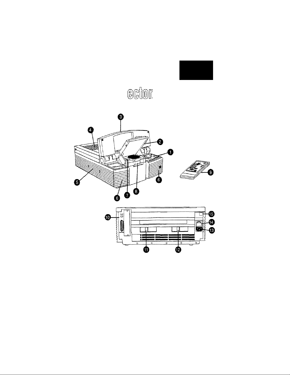
The Proxima® Desktop Projector*'’^^ and Remote Control:
Control Panel
1)
Mirror Assembly
2)
Cover Assembly
3)
Top Air Intake Filter
4)
Recessed Carrying Handle
5}
Front Air Intake Filters
6)
Cyclops Lens
7)
Projection Lens Assembly
8)
and Focus Ring
9) Remote Control
10) Connector Panel
11) Lamp Selector
12) Lamp Chamber Latch
13) Power Cord Receptacle
14) Power Switch
15) Circuit Breaker Reset Button
Page 8

PROXIMA®
De sk to p
:;OSER*S-GLJOÍ
ID.
230 0
Page 9

Warranty
PiDxknaCbipoiaaonvvanancsthai AfiProxima®EteiaopPiDieciDf™ produa
manufkiufEd by Projdma k fiee fixjin defeos in maKiials and "woikmanship under
nomral use during die Wananty Period. The Wananiy Period oornmenoes on the
day of purdiase by die end-user. Tie Warranty Period is one year. The Etesfcisop
Projeaor lamps aie not ooveiai by this Warranty.
The end-user’s sales receipt or invoke ¿owing die dace of pucdiase of the product
and the name of die Resdkris proofoi dare ofpuidia^ The Warranty eoends only
to die ordinal puidiaser and is not transfecablc.
During the Warranty Period PtoxiiTa will, at no ai&ional char^ n^jair or fqslace
di^ctiw parts or at the option of Pitsama, repkce die airiie unit.
This Iknitiai Warranty does not extend to any Prcdma product that has been
ikma^ri or b^n rendered defecrive (a) as a resdrof axkfai^ miaise or otka- abiis^
ib) by the use of pares not manufiemred or sold by Proxima; (e) 1^' modificarion of
the produa; or (d) as a rraik of savidng by tK»-auriioiEed pasonnd.
Limitation of
Warranties
FCC
Statement
Tra dema rk s
and Coisyrlghte
Tlie fcregoing Warrant)’" is iCfinsssl)' in lieu ofany other eqjiessed or implied
wanandes, induding, mdiout Hmitarion, ■ watranrics of tnerdiantabiliiy or fitness for
a particular purpose. To the eramt not pmhSiisal by kw, di staEtfflojywananries are
herdiy and excluded fiorn this Warranty. Proxima ejipressfy disdaiim all
wMimries not aai«i in thkliriiiiEd Wananiy.
Wanting: This a|uipmerit gaieiaics, uses and can ladiase radio fiequenqr eiMgy
and, ifirotinstaUed and Lised in aaoniancevrii the iristtactiorimattualjii:^ cause
interfeience to radio coiiuiiimicaoons. It has been ttsted and fixind to compb" vrfdi
limis for a Qass “A” compuring device pursuant to Subpart B ofPart 15 rf the
RXl iiuies, which arc dcsignai to prewide reasonable protection ag^ina: aicfa
interfetence sdasn operaKd in a corrfflMidal envirotunart Opetatkm of this
eqttipment fo a leskkntial a№ is lifcdy to cause iritErferenoe in which case the user, at
his own opense, will be required to take whatever UKasuKs may be necessay to
osrFeci knEtfetenoe.
of dieir reflective tmiieis. i
Piojecror 2300. Other IJ.S. and fors^ parents step
torfKESeddtip
sub^at-te'diat^ vrithout notice,'
i/94
Page 10

Oont^ent:!
Chapter 1
Introducing the
Proxima*
Deaktop
Projector™
Chapter S
Detailed Setup
Desktop Projector Family
Cyclops Interactive Pointer System
’NMiat’s in the Box?
.............
.........................................1—2
................................... 1—2
......
................................................... 1—3
Your Pfoxima Desktop Projector .........................................2—1
Getting Started....................
Opening the Projector
........... .
.....................................
..........................................
2-2
,„...2—2
Closing the Projector............................................... 2—7
Transporting the Projector ........................................
2—8
Connecting the Desktop Projector......................................2—9
Computer
RS-232
Powering Up
...................................................................2—10
...................................................................
2-13
.....................................................................
2—14
Applying Power to the Projector...............................2—14
Turning On/OIFthe Lamp
Projecting the Image
Image Size
..................................................................
......
.........................................2—16
.............................................. 2—17
2-17
Focusing................................................................... 2-18
Keysroniiig............................................................ .2-19
Page 11

Chapter 3
Using the
Desktop
Projector
The Control Panel
The Control Panel Keys
Arrow Keys
............................................................. 3—1
...................................................
.................................................................
3-1
3—1
BRIGHTNESS Ke>^................................................. 3-2
LAMP Key.....................................................................3-2
MENU/0(CTCLOPS) Key........................................... 3-2
SYNCKe>-s
The Menu Settings
Selecting and Changing Settings..................................
LANGUAGE
COLOR MODE
...................................................................
...............................................................
.............................................................
...
........................................................ 3-5
3-5
3-3
3-4
3-4
SOURCE.................................................................... 3-5
COMPORT.......................................................... .....3-6
BRIGHTNESS ...........................................................
CONTRAST
................................................................ 3-6
3-6
TINT........................................................................... 3-6
SYNC ..................................................................
......3-6
FREQUENCY.......................................................... ....3-7
SCREEN MODE............................................................3-7
PROJECTION MODE...................................................3-7
SETTINGS................................................................... 3-8
Warning and Alert Lights
03ŒRTEMP Warning Light ......................................
REPLACE LAMP Aleit Light
....................................................
....................................
3-9
3-9
3-10
The Remote Control................................................... 3—11
MENU/CYCLOPS Key
TEXT Key
..................
REV, PAUSE and FWD Keys
.............................................
3-12
.'............................................ 3-12
...................................
3-12
Page 12

CHapfcer ^ Cleaning
.........
IVtaintsenBnce General Maintenance
Switching Lamps.......................................................
Replacing Lamps....................................................... ...4-4
Chan^ngAir Filters
Changing the Remote Control’s Batteries...................4-12
Temperature Extremes
Chapter 5 Troubleshooting Chan....................................................... 5—1
TnoubleshoooinQ Where to Get Help
Appendix A
Specifications
Appendix B
Accessories & Replacement Parts
index
.......................................................... .4-2
..................................................................
......................................................
............................................
...........
................................................... 5—3
4—3
4—3
4-7
4—12
Page 13

Chapter 1
Introducing
the Proxima’®
Desktop
Projector™
Tile Próxima Desktop Projector family consists of portable, color
data and video LCD desktop projection products that make
sharing data and presenting information as easy as connecting
your computer to your monitor.
I=igur-e 1
The Pnoxims Desktop Projector in use
User's Guide • 1 -1
Page 14

Chapter 1 • introducing the Proxima® Desktop Projector
Oesktop
Pi-ojecfcor
Cyclops
lnt:eract:ive
Pointier
System
The Desktop Projector family includes the following products:
Family . T|je Desktop Projector 2800 is a video—ready, active—matrix
multimedia projector for all desktop projection applications.
• The Desktop Projector 2700 is an actiw-matrix, highperformance color projector with optional video capabilities.
• The Desktop Projector 2300 is an affordable high quality
color projector for all data desktop projection applications.
This manual covers only the Model DP2300.
All Proxima Desktop Projectors come Cyclops-ready. Cyclops is
an interactive pointer system that functions like a cordless mouse
and lets you control your computer and software from the
projection screen,
Not;e:
You cannot use Cyclops and Ptoxima’s Presentation
Control Software at the same time. To disable Cyclops and use
the software, hold the MENU key (Control Panel) down when
you turn the projector power on. Thh procedure will not work with
the remote control. To re-enable Cyclops, turn the projector off
and then power it up again.
Page 15

Chapter 1 • Introducing the Proxima® Desktop Projector
Whet;*s in t:he After y'ou’ve opened the box and removed the Desktop Projector
Box?
and shrink-wrapped accessory packs, make sure you have all the
items shown in Figure 2.
caution! The Desktop Projector should be treated like any
other precision optical instrument. Handle it carefuUy.
Proxima Desktop
Projector-
VGA. Video Y-Cable
CCASA-8)
Also included but not sheswn;
• Mac end VQA Video Terminators
• Dust Cover
• iS) AAA Alkaline Bartsines
• User's Guide
• Product Registration Card
Figure SI
items Included with the Desktop Projector
Remote Contarci Power Goioi
hp^acintosh Video Y-СаЫе
CCAS A -B3
CG 1 ooe-e}
Not;es The European version has three extra power cords for
Europe (part number Cl003-6), Great Britain (part number
ClOll—6), and Italy (part number CI012—6),
User’s Guide • l-S
Page 16

Chapiter S
Detailed
Setup
Your Próxima
Deskt:op
Projector
Before you begin, examine the components of the projector.
Figure 3
The Ppoxima Desktop Projector and Remote Gontrol
(1) Control Panel
(2) Mirror Assembly
(3) Cover Assembly
(4) Top Air Intake Filter
(5) Recessed Handle
(6) Front Air Intake Filters
(7) Cyclops Lens
(8) Projection Lens Assembly
and Focus Ring
(9) Remote Control
( 10) Connector Panel
■ (11) Lamp Selector
(12) Lamp Chamber Latch
(13) Power Cord Receptacle
(14) AC Power Switch
(15) Circuit Breaker Reset Button
User’s Guide • 2-1
Page 17

Ljnapter h¿ • LJetanea aetjup
Get;t;ing Opening the Projector
Started -- - - - - - - --- - - - - -
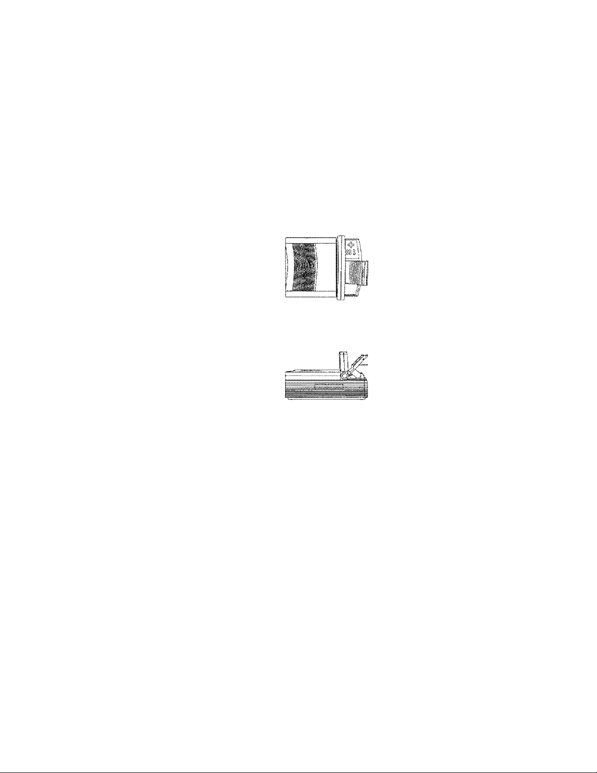
1. Place the projector on a solid, flat surface. The projector
- --
---- ----- --- ---
- -
- - - -- - - --
-
should be located at a right angle (perpendicular) to the
projection screen and parallel to the floor.
Top View
Hr
Perpendicular so the
projeccion screen
Side View
Parallel to the floor
Figure 4
Positioning the Desktop Projector
iMotie;
If you're using a media cart, make sure the wheels are
locked to prevent it ixom mowng.
o
CD
a-P • User's Guide
Page 18

Chapter ^ • Detailed Setup
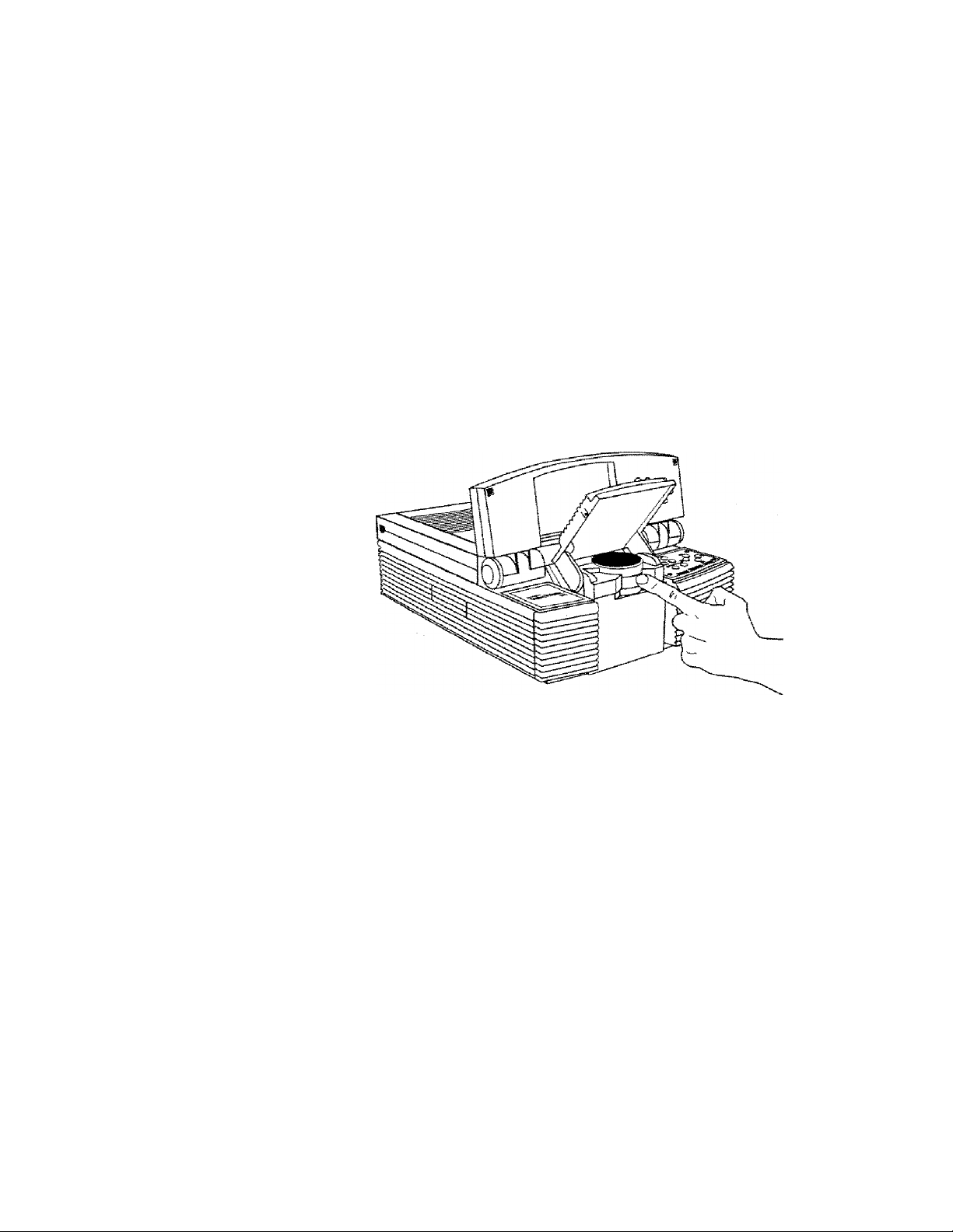
2. Grasp the front edge of the cover assembly at the upper front
of the projector. Raise it until it reaches the first stop. You can
also use the projector in the fully open position by raising the
cover assembly to the second stop.
Figure 5
Opening the cover assembty
CAtJTIOISf! The Desktop Projector's cover and projection
mirror assemblies have been designed to limit over-extension.
Appl}ting excessive pressure can damage the projector.
User's Guide • S-3
Page 19

3. Place your fingers beneath the mirror assembly (located at the
lower center of the front panel) and raise it into place until it
reaches a 45“ angle (approximately) relative to the top of the
lens assembly-
Figure 6
Raising the mirror assembly
2-^ » User's Guide
Figure 7
The Desktop Projsccor in the open position
Your projected image should fill the projection screen. If you
want to raise or lower the projected im^e, simply adjust the
mirror assembly to the appropriate angle.
Page 20

Chapter £ • Detailed Setup
CAUTIOiM!
DO NOT attempt CO lift or move the projector
by using the cover assembly or projection mirror as a handle.
IT IS STRONGLY RECOMMENDED THAT YOU CLOSE
THE PROJECTOR COMPLETELY BEFORE MOVING IT!
If you must move the projector while it is open, grasp it securely
at the sides by the lower part of the housing to support the weight
of the unit.
Figure B
Moving the ppoiector when open
User's Guide • S-5
Page 21

Chapter S • Detailed Setup
Using an AV Tripod
Located on the bottom of the Desktop Projector is a connector
for use with a tripod. Use only a heavy-duty, industrial audio
visual tripod that can support at least 20 pounds.
To attach the tripod to the projector:
1. Grasp the projector by the handle and stand it on its side.
2. Holding the tripod sideways, screw its threaded camera mount
into the connector on the bottom of the projector.
3. Extend and lock the tripod s legs.
4. Grasp the projector by its handle and place your other hand
under the unit (the side opposite the handle). Lift and turn the
projector into its normal operating position on top of the
tripod.
2-S * User's Guide
CALITIOWi
Be extremely careful when using the projector
with a tripod. The following precautions should be observed:
• You can mount the projector on a tripod by yourselfHowever, it is easier to do this if someone else is holding the
projector while you connect the mount.
• Make sure that the tripod legs and camera mount are
securely locked.
• Do not place the tripod and projector in any pathways that
you or your audience will be using during the presentation.
• Make sure that all cables are secured and out of the way. In
particular, be extremely careful of the power cord and any
extension cords.
Page 22

Chapter S • Detsiied Setup
Closing the Projector
To close the projector, reverse the opening procedures,
1. Rotate the projection mirror assembly forward and down until
it is in the fully dosed position.
2. Rotate the hinged cover assembly forward and down until it is
in the fully closed position.
CAUTIOiy! Gently dose the mirror and hinged cover
assembly. Forcing them to snap into place may damage the mirror
assembly. Close the assemblies in the proper order. Do not
attempt to dose the projector by only moving the cover assembly.
User's Guide
a-7
Page 23

Chapter 2 • Detailed Setup
Transporting the Projector
CAUTiOIM!
Do not move or transport the Desktop Projector
without securely closing the projector and disconnecting all of the
cables.
The Desktop Projector has a recessed carrying handle located in
one of the side panels.
1. Push in on cither end of the hairdle. Pull the handle up,
2. Release the handle. The spring-loaded mechanism will retract
it back into the body of the projector.
2-S User's Guide
Figure B
Accessing the handle
Nalbe: The projector has protective feet on the side opposite the
handle as well as on the bottom.
Page 24

Chapter 3. • Deteiled Setup
Connectirig Take a moment to look at the projector’s rear connector panel.
t;he Deskt;op
Proiector
Figure 10
The Connector Panel
Connector
1 RS-232
a
COMPUTER Connects computer video
For using the optional
Cyclops interactive
pointer system or
Presentation Control
Software
to the projector
Description
User’s Guide • 2-0
Page 25

Connecting Take a momenr to look at the projector’s rear connector panel,
the Oesktop
Projector
Figure TO
The Connector Pane!
Cortnecl^or Oe sci'lpt;i an
1
BS-S32 For using the optionai
2
COMPUTER Connects computer video
Chapter £5 • Oetailad Setup
Cyclops interactive
pointetr system or
Presen-cation Contra!
Software
to the projector
User's Guide • 2-S
Page 26

Chapter 2 • Detailed Setup
COMPUTER
The video Y-cabie allows you to connect your computer to both
the Desktop Projector and to a separate computer monitor so that
you can view computer video output on the monitor and
projection screen simukaneousiy.
Desktop Computers
If you are using a desktop computer, regardless of whether it’s an
IBM compatible or a Macintosh system, the sequence for
connecting it to your Desktop Projector is exactly the same. Use
the Y^'Cabie appropriate to your system. For IBM compatibles, use
part number C454—6; for Macintosh systems, use part number
C464-6.
2-10 » User's Guide
Pigur*e 1 T
VGA and Macintosh oonneccors
1. Turn off ail power to your computer, its monitor, and the
Desktop Projector.
2. Unplug your monitor cable from your computer’s video
monitor port and attach the cable to the short end of the
Y-cable (marked MONITOR).
3. Locate the Y-cable's common end, marked CPU/MAC II for
Macintosh systems and COMPUTER/VGA for IBM
compatibles. Plug it into the computer's monitor port.
Page 27

GhBpfcer £5 • Deeeiled Setup
4. Insert the Y'Cable’s large, 25-pin connector (marked LCD)
into the Desktop Projector's COMPUTER port.
Figure IS
VC3A connecstions
Figure 13
Macintosh connections
User’s Guide • 2-1 1
Page 28

Cheptep a • Deteiled Setup
ISiot;e: if you want to use your desktop computer without a
monitor, connect one of the supplied video terminators to the
short end of the Y-cable (marked MONITOR). Use the
appropriate terminator for your system. For IBM compatibles, use
part number C936; for Macintosh systems, use part number
C935.
Natet30oks/Laptops
Use the Y-cable appropriate to your system. For IBM
compatibles, use part number C454-6; for Macintosh systems, use
part number C464-6.
1. Turn off all power to your notebook or laptop computer and
the Desktop Projector.
2. Locate the Y-cab!e's common end, marked CPU/MAC II for
Macintosh systems or COMPUTER/VGA for IBM
compatibles. Plug it into the computer's monitor port.
2-1 2 » User's Guide
3. Insert the Y-cable s large, 25—pin connector (marked LCD)
into the Desktop Projector's COMPUTER port.
4. Attach the appropriate video terminator to the short end of the
Y-cable (marked MONITOR). For IBM compatibles, use part
number C936; for Macintosh systems, use part number C935.
ISlote!
If you don’t get an image (i.e., your Desktop Projector is
unable to project an image at the same time that your laptop
computer displays a screen image), refer to your computer's
reference materials for information on how to switch between the
internal screen and the video port.
Page 29

Chapter 2 • Detailed Setup
IMot;e: If you’re using your notebook or laptop computer with
an external monitor, follow the procedure described in the
previous section titled Desktop Computers.
Special Conflguratians
If your computer has an internal monitor but does not have
external video capabilities (i.e., Macintosh SEs and certain
Pow’erBooks), you will need a video adapter card in order to
attach the Desktop Projector. Setup for a third-party adapter is
identical to the procedures outlined in the previous section titled
Desktop Computers.
Contact your dealer, Proxima Customer
Seivhce, or a third—party supplier for more information regarding
video adapters.
RS-232
The RS-232 port allows you to use the optional Cyclops
interactive pointer system or the Proxima Presentation Control
Software. Instructions for connecting the appropriate serial or
ADB cables are included with each of these products.
User’s Guide ♦ 2--13
Page 30

Chapter 2 • Detailed Setup
Powering Up
Your Desktop Projector and external monitor (if you are using
one) must be powered up before turning on your computer, so
chat yom computer properly senses each display during its boot
up sequence.
Applying Power to the Projector
On the rear connector panel of the projector, you'll find a power
cord receptacle and an AC POWER switch.
.... . . . . . .......I...
Figure 1<*
Power receptscle CS1, AC POWER switch C2), and circuit
breaker reset button £33
.
S-1^ • User's Guide
To power up the projector;
1. Plug the power cord into the Desktop Projector's power
receptacle at the rear of the unit.
CAUTiOISli Plug the AC power cord into the Desktop
Projector BEFORE connecting it to an electrical outlet. If you
plug the power cord into the wall first, it might damage the
projector.
Page 31

Chapter 2 » Detailed Setup
2. Connect the power cord to a properly grounded wail outlet.
3. Move the AC PON^TER switch to the ON position. The
projector's fan will begin to run. If you do not hear the fanj
refer to Chapter 5, Troubleshooting.
4. Turn on your monitor and computer.
CAUTION!
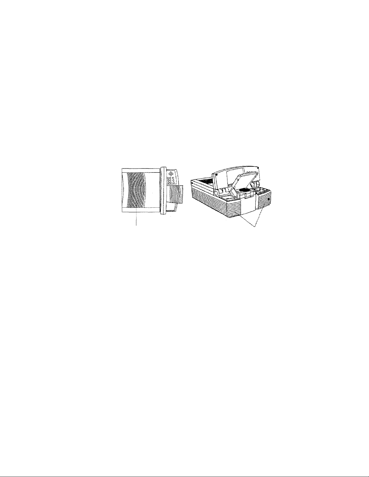
Locate the air intake and exhaust grills on the top
cover and co the left and right sides of the projection mirror
assembly, and the exhaust grills on the rear panel and side of the
projector. Never operate the projector if these grills are closed or
obstructed, or if the electric fans are not running.
¡Figui'e 5
Allow for proper air flowi
No-ee: if you turn the Desktop Projector off while the rest of
your computer system is running, your external monitor will go
blank. This is normal. Just turn the Desktop Projector on again
and your monitor display will return.
User's Guide » 5
Page 32

Chapter S • Deteifed Setup
Turning On/Off the Lamp
’'iCTen you first turn on the projector, the lamp will be on. Press
the LAMP key on the Control Panel or remote control to turn the
Desktop Projector's lamp off. Pressing the LAMP key again will
turn the lamp on. The lamp turns on slowly to prolong lamp life.
Brightness
Sync
• •
Menu/O
Figur-o a G
The LAiVlP key
IMotes
Turning the lamp off does not cut power to the
projector. The fan will still operate. You must move the AC
POWER switch to the OFF position to completely power down
the projecror.
2-1B • Usen's Guide
Page 33

Chapter 2 • OetailecJ Setup
Projecting
the Image
Your next step is to adjust the projected image for size and clarity,
Image Size
The size of the projected image varies according to the distance
from the Desktop Projector to the projection screen. The
following table shows the projected image size (measured
diagonally) based on the distance from the projector to the screen.
Distance from Screen
4 ft/1 .2 m
6 ft/1 .B m
S m 7'2”/1 B£.0 cm
1Q ftC3,0 m
1 2 ft/3.B m 10S.7'"/278,B cm
1 A ft/4.3 m 128"/325.1 cm
Diagonal Image Size
35’7SS.S cm
53.SV1 35.S cm
0O.SV22B.S cm
12SV3SB.1 cm .
Figure ■!
Diagonal measurement of projected image when Desktop
Projector is 1-4' M.3 m3 from projection screen
7
User's Guide • 2-1
~7
Page 34
Chapter 2 • Detailed Setup
Focusing
You can use the title screen image that appears when you first
start up the projector to make your adjustments.
Using a thumb or fingertip, rotate the focus ring to the right or
left for the dearest displayed image.
2-IS • Ussp's Guide
Figui'e 18
The projectar iene focus ring
Page 35

Chapter g
Keystoning
Detailed Setup
The normal projected Image will have a rectangular shape.
Keystoning is when the projected image becomes trapezoidal.
800
600
400
200
0
APR I MAY I JUN j JUL |
_ ||H hP
IMormat Image
FigeMre 1S
Normal ve. keystoned imsges
Keystoned Image
Keystoning occurs when the front of the Desktop Projector is not
perpendicular to the projection screen (the vertical plane) or when
it’s not placed parallel to the floor {the horizontal plane).
Keystoning also occurs when the Desktop Projector is tilted
sidewaj's.
Dser’s Guide • 2-10
Page 36
Chapter £ • Detailed Setup
To correct for keystoning, always make sure that the projector is
at a right angle to the screen in the horizontal plane. The
pro jector is properly aligned if the top and bottom of the
projected image are equal in length and parallel to the floor.
Top View
Perpend i,Gu lor to the
prolection screen
Side View
2-2D • User's Guide
Pa-rallei to the floor
{figure SO
Positioning the Desktop Projector
In order to allow you to project images high enough for the entire
audience to view, the Desktop Projector has been designed to
minimize this effect. A 10.5° correction for keystoning is built
into the projector.
Page 37

CHap'ter 3
Using the
Desktop
Projector
This chapter provides detailed information on the Desktop
Projector settings, the Control Panel functions, the Menu
Window, and the warning indicators.
"The Control
Pane!
The Contirol Arrow Keys
Panel Keys
The following figure shows the Control Panel configuration for
the Desktop Projector 2300.
Figure ai
The Contno! Pane!
The four arrow keys allow you to:
* Make small adjustments to the projected image's position on
the screen. Pressing an arrow key shifts the projected image
in the direction indicated by the arrow,
Sync
* Access and modify settings within the Menu window.
For more information, please refer to the section titled The Menu
Settings Iztcr in this chapter.
User’s Guide • 3-1
Page 38

Chapter 3 • Using the Desktop Projector
BRIGHTNESS Keys
The BRIGHTNESS keys increase and decrease the intensity level
of the projected image. Press the top key to increase brightness
and the bottom key to decrease it,
LAMP Key
The LAMP key toggles the projection lamp on and off,
• If you turn the lamp off but leave the projector on, the fan
will continue to run.
• You can rum the projector off without allowing the fan to
cool down the unit. However, the projector will take a little
longer to cool.
MENU/ © CCYCLOPSI Key
3-3 • User's Guide
This key allows you to access and modify the current Desktop
Projector settings in the Menu Window, which appears in the
lower portion of the displayed image. This key also allows you to
initiate the light measurement sequence for calibrating the
optional Cyclops interactive pointer system (part number A2060)
and to disable Cyclops when you wish to use the Presentation
Control Software.
1. Press the MENU key to display the Menu Window.
2. Exit the Menu Window by pressing the MENU key again.
For more information, please refer to The Menu Settings section of
this chapter.
Page 39

Chap'Cer 3 • Using the Desktop Projector
m
IMotie:
Holding the key down for several seconds initiates the
Cyclops light measurement sequence. For more information^
please refer to the Cyclops Users Guide.
fSlo^e: You cannot use Cyclops and Proxima’s Presentation
Control Sofrware at the same time. To disable Cyclops and use
the software, hold the MENU key (Control Panel) down when
you turn the projector power on. This procedure will not tuork with
the remote control. To re-enable Cyclops, turn the projector off
and then power it up again.
SYNC Keys
The SYNC keys are used to compensate for fine variations in the
timing of a computer's video signal. Adjust this setting if you see
uneven horizontal features, streaks or shimmering in a graphics
image. Press the upper or lower SYNC key until the image
stabilizes.
User's Guide
3-3
Page 40

Chapter 3 • Using the Desktop Projector
The IS/ienu
Set;t:ings
The Menu Window appears in the lower portion of the projected
image, displaying the currently selected settings for the Desktop
Projector. Press the MENU key on the Control Panel or the
remote control to display the Menu Window.
Selecding and Changing Settings
To move to and change a setting:
1. .Access the Menu Window.
2. Use the Right or Left arrows kej' to move to the setting that
you wish TO change.
3. Use the Up or Down arrow key to change the setting.
The active setting (the one that you can change) is
indicated by a red outline.
Proxima ◄ Select ► A Adjust
T
3^4
« User's Guide
Language Color Mode Source
English
Brightness
■ ■■ ■ ■■
Frequency
800
24,389
Contrast R Tint G
Screen Mode
Noima!
□
Figure 8&
THe Menu Window
VGA 640x480
MBS
I Projection Mode j
■ Normal
□ Rear
Com Port
Cyclops 4.0
Sync
Settings
□ No
■ Yes
Current
Page 41

Chapter 3 * Using the Desktop Projector
LJXNGUAGE
LANGUAGE allows you to select a particular language set for the
Menu Window. Languages displayed include Dutch, English,
French, German, Italian and Spanish. Use the Up or Down arrow
key to cycle through the choices.
COLOR MODE
This setting allows you to select the color mode most suitable for
the type of image you’re projecting. Use the Up or Down arrow
key to cycle through the choices.
Coior
IVIodci
a TypiesHy r^sult-s in
2.1 B7 Beat for business
1
s.sas Best for graphics of
2.a,3as
Descripeloo
Icswer CO tor
resolution but
bright^ image
gr^phiCB or other
applications
repufring bright, high
contimst cators
medium complexity
Besc
fan
complex
corrtputBT graphics
end animacion
Prtrneiiw tJsBe
Text screens
Computer video
Computer video
Computer video
\
SOURCE
SOURCE tells you what input has been detected by the projector.
SOURCE doubles as both a status and selection box.
The Desktop Projector selects the best possible value based on the
mcoming signal. If the image doesn’t look right, use the Up or
Down arrow key to make an alternative selection.
User's Guide
3-5
Page 42

Chapter 3 • Using Che Desktop Projector
COM PORT
This value reflects the current status of the projector's serial port.
Possible values include Active, Inactive and Cyclops.
Active
Inactive
Cyctops Cyclops is atitached and funedoninQ.
BRIGHTNESS
The projector has detected activity
on the sarial port.
No activity is detected on the serial
port.
This control is used to increase and decrease the overall brightness
of the projected image. It functions the same way as the
BRIGHTNESS key on the Control Panel. Use the Up or Down
arrow key to increase or decrease the brightness level.
CONTRAST
This control allows you to adjust the difference between light and
dark segments of the projected image. Use the Up or Down arrow
keys to adjust the contrast level.
TINT
The TINT control adjusts the Red and Green color balance.
SYNC
“t rh is setting if you see uneven horizontal features, streaks or
meting in a computer video image. Press the Up or Down
,iw key until the image stabilizes.
Page 43

Chapter 3 • Using the Desktop Pro|ector
FREQUENCY
This adjustment allows you to synchronize the Desktop Projector
with your video source. For example, if your computer has a video
card with non-standard signal components (i.e., h-sync or v-sync),
the projected image may look jittery, contain bands, or appear
out-of-focus. Use the Up or Down arrow key until you find the
setting that projects the best image.
IMo^e? Always adjust SYNC before changing the FREQUENCY
setting.
SCREEN MODE
This control allows you to switch between NORMAL and
REVERSE video modes. REVERSE is used primarily for viewing
text screens.
PROJECTION MODE
This function can be used to flip the displayed image, allowing
the Desktop Projector to be used with a rear projection screen.
PROJECTION can be used in all video modes. Use the Up or
Dowm arrow key to cycle between the NORMAL and REAR
options.
User's Guide • G-T
Page 44

Chapter 3 • Using the Desktop Proiector
SETTINGS
This control allows you to retrieve rlie factory—set or stored
settings, or to save the current settings.
Store Settings
The default value for STORE SETTINGS is NO. If you wish to
save the current settings, use the Up or Down arrow 'ksy to select
YES. The new values become the stored settings under the
RETRIEVE SETTINGS option. These settings are retained when
the projector is turned off and will be in effect when it is turned
back on again.
You can also use STORE SETTINGS in any of the projector s
various video modes (i.e., VGA, Macintosh II, etc.). In each case,
the current settings can be stored for every entry available in the
SOURCE box.
3-0 * User’s Guide
Setrieve Settings
The RETRIEVE SETTINGS option is located in the right
portion of the SETTINGS box. To access the RETRIEVE
SETTINGS option, go to the STORE SETTINGS box and press
the Right arrow key. Three sets of settings can be retrieved:
• CURRENT - Settings in effect before you selected
RETRIEVE SETTINGS. If you select CANCEL, you will
return to the current settings.
• STORED - Settings whose values you have previously
stored. If the STORED entr)'- is grayed out, there are no
user-stored settings available.
• FACTORY - The built-in default settings for each video
mode.
Page 45

Chapter 3 • Using the Desktop Projector
Warning and Warning and alert lights located on the projector's control panel
Alert
i-ights provide you with an indication of the Desktop Projector’s
operating condition.
Syne
Brightness
UmtuQ
Fisura 33
Warning lightB
OVERTEMP Warning Light
The OVERTEMP warning will light in the unlikely event that
the projector reaches an over—temperature condition. A
thermostat will switch ofFiamp power until the projector cools.
CAUTIONS
DO NOT TURN OFF THE PROJECTOR'
The power must be left on so that the fan continues to cool down
the unit.
User's Guide • 3-S
Page 46

Chapc-er 3 • Using che Desktop Pr-ajector-
If an OVERTEMP condition occurs, perform the following
checks while you allow the projector to cool;
• Verify that the room temperature is below 80° F (27° C),
• Check the intake grills and exhaust vents. Clear any
obstruction to the air flow.
• Check the filter elements. Clean or replace them if necessary.
For more information, please refer to Chapter 4,
Maintenance.
• Check the rear and side exltaust vents. If the projector has
reached an OVERTEMP condition and the fan is working,
you should feel a strong rush of hot air from the vents. If the
fans are not w'orking, the Desktop Projector needs service.
After the projector returns to its normal operating temperature,
the OVERTEMP warning light will go out. In order to turn the
projection lamp back on again, you must press the LAMP key on
the Control Panel or remote control.
3-10 • User’s Guide
P4ati&t The remote control’s LAMP key will not function after
an OVERTEMP condition until the lamp is turned on from the
Control Panel.
REPLACE LAMP Alert Light
The REPLACE LAMP aien light will illuminate if the active
and/or alternate projection lamps have burned out, or if the lamp
selector is not fully engaged.
You can continue your presentation if one lamp has burned out.
REPLACE LAMP remains on as a reminder to replace the burned
out lamp.
Page 47

Chapter 3 * Using the Desktop Projector
The Remote
Control
The remote control contains all the key functions available on the
Control Panel.
¡Mote:
For best results, always aim the remote at the projection
screen or at the projector's front edge.
The remote control also provides access to additional functions
not available on the Control Panel or through the Menu
Window.
MSNU
□ □
- SYNC
m nn
■ BFllGHTilESS -r
Ten
□
Figure S«S
Remote contro! urtic
Desidop Rijiiif.
Btue keys = PC/MAC fetmte software
2300
User's Guide • 3-1 1
Page 48

Chapter 3 » Using the Desktop Projector
MENU/CYCLOPS Key
This button is used to display the menu and to calibrate the
optional Cyclops interactive pointer system. Its function is
iden tical to the MENU/ @ key on the Control Panel.
IMat;e:
Unlike the M.ENU/© key on the Control Panel, the
remote control’s MENU/CYCLOPS key^ cannot be used to
disable Cyclops.
TEXT Key
The TEXT key toggles berR'een the Graphics mode of 640 x 480
ltn.es and the Text mode of 720 x 400 lines. A DOS text screen is
easier to view when in text mode.
REV. PAUSE and FWD Keys
These three control keys work with Proxima’s Presentation
Control Software, which can be used to sequence electronic slides.
For more information, please refer to the Presentation Control
Software Guide comes with your software.
3-12 • User's Guide
Page 49

Chapt:er <4
Maintenance
There is very iitde involved with the care and maintenance of
your Desktop Projector. However, common sense and periodic
maintenance will ensure top performance.
An optional maintenance kit {part number A60) is available that
includes the following materials:
• (2) Halogen ianips
• Lens cleaning fluid
• Lens tissue
• Top and front air filters
• Can of compressed air
The lamps, lenses, mirrors, and LCD panel have been carefully
aligned at the factory to give you the clearest, brightest image
possible. However, physical abuse can cause misalignment or
damage to the optical elements. Take appropriate care in use and
handling.
CAUTIOIM!
The Desktop Projector contains sensitive
circuitry and optics. Protect it from potential fluid spills.
User’s Guide • <4-1
Page 50

Chapter A • Maintenance
Cleaning
From time to time, you’ll need to clean the optics on the lens and
mirror assembly.
Projection Lens or Minror
1. Take a piece of lens tissue and form it into a loose swab. Wet
it with lens cleaning fluid or alcohol and gently move it over
the lens or mirror surface.
2. Take another part of the lens tissue not touched by your bare
fingers and repeat the process, going over the lens or mirror in
another direction.
3. Repeat steps 1 and 2 until no smudges or particles can be seen
when the lens or mirror is illuminated by a strong light. If the
lens or mirror is extremely dirty, it may be necessary to use
several pieces of lens tissue. Water may be used if alcohol is
unavaikbie.
CAUTIONS Acetone should NEV'ERbe used because it may
remove the pain: from the metal lens or mirror mount and leave a
residue on the glass surface.
■AS.
• User's Guide
Page 51

Chapter 4 • Maintenance
General
IV!aint:enance
Switching Lamps
If your projector lamp burns out during a presentation, the
LAMP SELECTOR switch allows you to quickly and easily
change to a backup lamp.
Figur« Se
The lamp selector
You do nor have to turn off projector power before switching
lamps. As you move the LAMP SELECTOR switch to its
opposite position, you’ll feel the switch dick into place. The
alternate lamp will illuminate, coming to foil brightness slowly to
extend the life of the lamp.
User's Guide • 4-3
Page 52

Chapter -4 Maintenance
Replacing Lamps
Leave the Desktop Projector running with the lamp off prior to
changing lamps. This will allow the fan to run and speed the
cooling of the lamp chamber. Don’t open the lamp chamber until
the projector has cooled.
1. Remove the power cord. As a built-in safety feature, the lamp
2. Move the lamp chamber latch to the right. The cover panel
chamber cannot be opened unless the cord is removed.
will “pop” open.
•4—4 • User's Guide
Figure 26
Opening the lamp chamber latch
Page 53

Chapter A • Maintenance
3. Lift the cover until it stops. Do not force the cover! The lamp
chamber is now accessible.
Figure H7
Opening the lamp chamber
CAUTION!
The lamp chamber gets very hot during
operation. In particular, the ceramic socket at the lamp’s base can
get extremely hot! Use appropriate care when opening the lamp
chamber or changing lamps. Mate sure that the lamp chamber
and lamp have cooled for at least 3 minutes with the fan running.
User’s Guide
Page 54

Chaoter ^ • Maintenance
4. A lamp release lever is located at the front of each ceramic
lamp socket. Push the lever to the outside to release the lamp.
Remove the burned out lamp from its socket and replace it
with a new one.
IFigur® HB
Push the reiease lever to release the Samp
a Usen's CBuicfe
CAUTIOIM! Always use a clean cloth or tissue to handle the
lamp. Touching the lamp or otherwise coniaminaring its surface
can damage it. If you do come in contact with the lamp surface,
clean it thoroughly before use.
5- Close the lamp chamber by firmly pressing the cover down at
the center of its upper rear edge until the latch engages. The
lamp chamber latch will return to its center position, providing
access to the power plug receptacle.
6. Replace die power cord.
Page 55
Chapter A • Maintenance
Changing Ain Filters
You should change or dean the three air intake filters after every
250 operating hours to assure proper cooling. These filters are
located on the left and right sides at the front of the projector s
lower case and under the griM in the top covet.
Top Air
Fiiter Gnil!
Figure ES
The air intake filter grill assembiias
Front Air
Filter Grills
User’s Guide «
Page 56
Chapter <4
Maintenance
Front Air Intake Filter Assemblies
1, Release latches are located on the lower portion of the two
front filter grill assembly frames. Press these up as you pull the
grill assemblies out.
-4-S • User’s Guide
FiguPE 30
Removing the tower front air fitter grit! assemblies
Page 57
Chapter 4 » Msintenance
2. Remove the foam air filters.
Figure 31
Sepersting ths air fiiter from the filter grill
3. Depending on their condition, clean or replace the filters.
• To dean a filter, wash k in a mild solution of soapy water,
rinse and let it dry.
• To replace a fiiter, refer to Appendix B: Accessaries &
Replacement Parts for ordering information.
4. Clean the grill vents using a cloth or the can of compressed air
in the optional maintenance kit,
5. Reassemble the air filter assemblies and replace them.
User's Guide » ¿1—3
Page 58

Chapter ¿1 « ivtsinfeenance
Top Air Intake Fitter Assembly
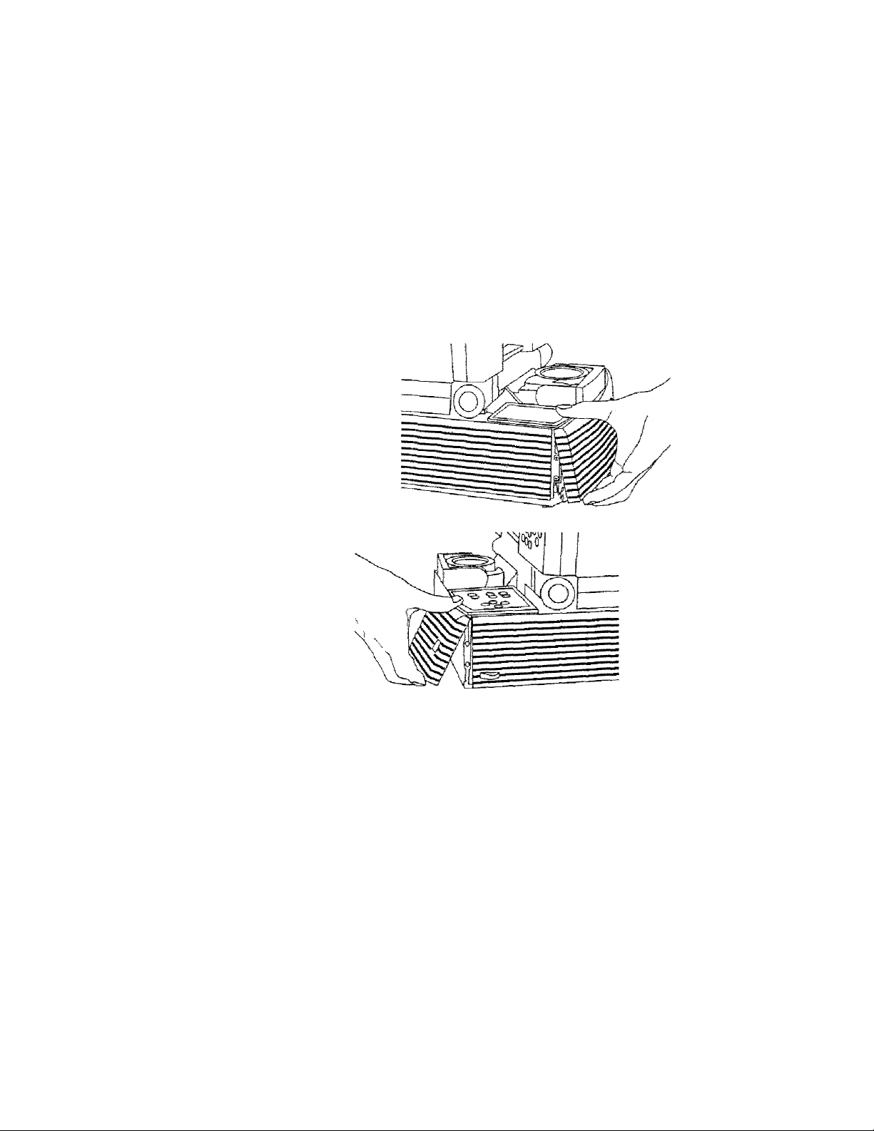
1. To rekase the top air filter assembly, place both thumbs iaio
the two depressions located <m the rear of the top filter griii
assembly frame. Press down and back towards the rear of the
unit. The front edge of the grill wili pop up.
Figure 3S
Removing: tjpe air filter griti а&эетЫу
-4-10 ♦ User's Guide
2. Grasp the forward edge of the grill and Mft to remove it.
Page 59

Chapter >4 • Maintenance
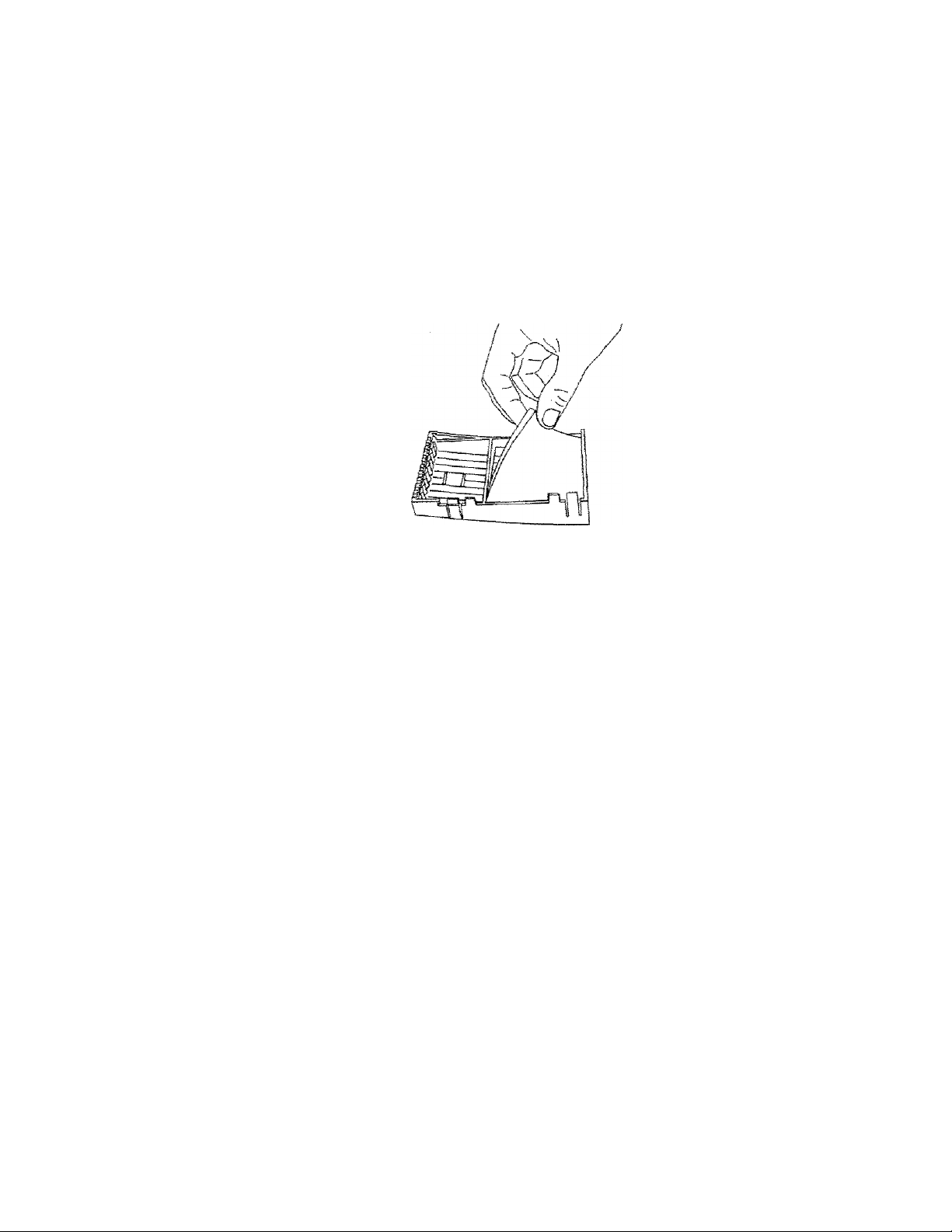
3. On the bottom side of the grill assembly, you will see a
retaining grid. Grasp the tab at the center to remove it.
Figure 33
SepBPBCing the sir filter from the fitter grili
4. Remove the foam air iiiter.
5. Depending on its condition, clean or replace the iiiter.
6. Clean the grill vents using a cloth or the can of compressed air
in the optional maintenance kit.
CAUTIOM!
Be careful not to aim the stream of air towards the
projector, as this could force dust particles inside the unit.
7. Reassemble the air filter assembly and replace it.
User's Guide • «4-1 1
Page 60

Chapter <4 • Meintensnca
Changing the Remote Controi’s Batteries
To iristall or change the two AAA alkaline batteries in the remote
control unit:
1. Locate the batter}- compartment at the lower rear of the case.
Slide the cover off the battery compartment.
2. Remove the old batteries and replace them with new ones.
Make sure to align the batteries in the proper direction.
■4-IS • Uaen’s Guide
3. Replace the cover on the batter}' compartment.
Temperature Extremes
The projector should not be stored in excess of 140° F (60° C).
The ideal operating temperature is below 80° F (27°C). After
exposure to extremely low temperatures, allow the projector to
warm up before using it.
Page 61

Chaptser 5
T poubleshooting
No image projected
REPLACE LAMR
indication
Displayed image not
square Ckeystoned)
Projected fmege out
of focus
Projected image
larger chan screen
Projected image
smaiier than screen
r^o computer image
projected
Likely Oauee Poaaibte Soiut;iante3
No power to projectop
Lamp not on
Circuit breaker engaged Correct overioad
CDVERTEMP indication Allow projector to coal;
Burned out !ampCs3 Move iamp selector
Projector not placed at
proper angie to
projection screen
Projector not horizontai
Proja-ction.tens not
focused
Projector too
screen
Projector too close to
screen
Loose cable Check and secure cable
No power to computer Turn on computer
Inconnpstible video
system
No externst monitor
far
from
Turn power ON
Check AC cord
Check power to
eiectrical outlet
Turn tamp ON
situation; press circuit
breaker reset button
to disengage
torn lamp ON
Bwitoh to opposite
position
Replace lampCs)
Adjus-ti relative postoions
of projector and
sc ma n
Levei projector
Adjust projecdon lens
focus
Move projector closer to
sc r^-en
Move projector away
from screen
conn:ect.lons
If poBsibia, check
computer with enothsr
monrixjr
Use included video
terminator appropriate
to your aystem
Switch between interns!
screen and video port
Oeer's Guide • 5-1
Page 62

Chap&BP 5 » Troubieshooting
Problem Likely Ceuse
No image on
computer screen
MoniDchrome
color monsrar
Screaks an monitor
Faints screen Low intensity
Jittery, fuzzy letters Out of sync
Image off-center PasiCion controls Csrrow
Cannoc
image on screen;
scrambled image
“Shimmering” colors SYNC OP BRIGHTNESS
OVERTEMP
indication
Remote Control
doesn't work
on
get entire
Power switch off or
projector not on
Cable not connected
Computiep was turned
on before projector
Computer's external
video port sec
incorrectly
Video oabis plugged
into computer is
upside-down
keys]
Compatibility problems
MiEBtignment or damage
to optical etements
Compatibility problems
out of adjustment
Air ventCsJ clogged
Internel fan failure
Batteries upside-dawn
or old
Projector's IH receiver
window blocked
Possible Sotufciontsi
Ppojecter must be on for
computer monitor
display
Connect cable'
Turn projector on and
re-boot computer
Set computer’s external
port to "color"
Check and re-set cable
connections
Adjust BRIGHTNESS and
CONTRAST
Adjust SYNC control
Adjust position controls;
if
image will not center,
obeok for compstifaitity
problems
Verify projector is image
compatible with one of
the standards listed in
Appendix A;
Speciffcatfona
Ppojecfeop requires
servicing
Verify projecton is image
compatible with one of
the standards listed in
Appendix A:
Specfffcations
Adjust SYNC or
BRIGHTNESS
Allow projector to cool;
clear obstructions
from vents
Clean and replace filters
as necessary
Allow projector to cool
Check for fen and blower
operation; service if
necessary
Check battery placement
or replace with new
batteries
Remove obstructing
object
5-S » User's Guide
Page 63

Chapter 5 « Troubleshooting
Where t;o Get
Help
If at any rime you need help;
1. Check the Troubleshooring Chair.
2. Call your dealer’s technical support line and expiain your
problem.
3. Call Proxima at:
U.S.A- and Canada;
(619) 457-5500
Press 1 for Customer Service.
(619) 457-8542 (Fax)
Outside U.S.A. and Canada:
(619) 457-5500
Press I for Customer Service.
(619) 622-0173 (Fax)
Europe:
+31-43-650 248
+31-43-649 220 (Fax)
User’s Guide • 5-3
Page 64

Chapter- 5 • TpoubieshooCing
Returns
if the Desktop Projector or any of its accessories are determined to
be defective;
1. Co-ntact Proxima Customer Service to request a Remm
2. Send the defective unit with the RMA number dearly marked
Material Authoriiation (RMA) number.
on the outside of the shipping box, freight prepaid, to:,
U.SA. and Canadar ■
Proxima Corporation
RMA#
9440 Carroll Park Drive
San Diego, CA 92121
Europe:
Proxima Corporation
RMA #
Horsterweg 24
6191 RX Seek
The Netherlands
5-4
• User's Guide
3. Pack the projector in its original box for safe shipment, if you
no longer have the original shipping materials, contact
Proxima Customer Service for pack^ing.
Page 65
Appendix A
Specifications
Projector Type
Computer Compscibility
Portable Color Data Projector
IBM PC, PS/2 and compatibles CVGA. EGA ,
CGA'’ , VESA BAO X ABO, T'SHzJ
Olivetti®/ATGT® CVGA, EGA, CGA) ^
NEC S801 (VGA. EGA. CGA)
Hercules , Hercuias Plus
*1 *1
Apple Macintosh il. LC, Quadra, Centris,
Performa and PowerBook ^
Apple Macintosh Classic, Classic 11. compact
Macintosh family®
Apple !!GS
interface Connectors Computer: DB-B5 to appropriate video
Y-cable
nS-232: Full duplex w/ Mini DIN S
j
Cyclops; Recessed card edge connector
LCD Psnel Color-stripe STN (Super-Twisted Nematic)
ReaaluCion SAO X ABO pixels
Number of Colors Maximum of 2A,3B9 coiors
Response Time 1 DO milliseconds itypicaO
Contrast Ratio 20:1 icypical)
Brightness
Lsmp
Oimensions
A5 ANSÍ lumens (typical)
FXL AIO watt Tungefcen Halogen Quartz
1 3,1 ” W X 1 T" L X 3.3” H
33.3 cm W X A3.2 cm L x 1 A.0 cm H
Weight . 1 B.5 lb CB.S kg)
Projection Distsnoe A‘ Cl',2 m3 to 1 A' CA.3 m) from screen
Screen Image Size
Lens
Keystone Correction
Power Requirements
Storage Temperature
35” CBS.S cm) to 1 2B" (325.1 cm) diagonal
F/S, 260 - 2SO mm focus length
Normal at -f1Q.5 ° projection angle
Auto switching from 90 - 130 VAC and 200 -
a AO VAC, AT to B5 Hz
-A“ F to 1AO° F C-2D° C to BO° C)
Humidity' Tolerance 1 Qtfa to BSPfa nonrcondensing
Approvals
Warranty
^
Osbies for shese
^Appfs Power&ook 'too, 7-40,
•“S'
Requires 3rd
p,srt:y
systems
snd
1 70
exte mef video adapter
require 3rd partly extemaf video adapter
FCC Glass A. UL. TÜV, CSA
One year on ports end labor. No warranty on
projector lamp.
ors
nor
¡nducf&cf
User’s Guide A-1
Page 66

Appendix B
Accessories S.
Repiacement
Parts
Aeeeseory
Cyciops earners
and Wand
Dual infcenaifci'
Laser Pointer
Desktop
Projector™ Soft
Carrying Cass
Desktop
Projector™ Hard
Csrrying Case :
Video Y-Cabie Connects to IBM
Video Y-Csbie
Video Y-Gabie
Interface Kit Connects Mac SE or
Interface Kit
Computer- grade
Surge Protector
Video Terminator
Kit
Maintenance Kit Contains extra halogen
Interactive pointer system
Activates Cyclops sensor
Accomodates the ;
Accomodates the
Connects to Apple I IOS
Connects to INiEC
Connects Mac Classic to
Protects projector and
VGA terminators AAi
Oescript^ion
from up to SS' away
Desktop Projector and
accessories
Desktop Projector and
accessories
EGA/CGA, Hercules,
Herculest. end Olivetti
OEC video standards
computer
PC-0001 computer
SE/30 to Desktxjp
Projectsor
Desktop Projector
other attached
equipment from power
surges and spikes.
North America use only.
Gomes with SIO.OOQ
equipment guarantee.
lamps, lens cleaning
fluid, lens tissue, extra
air filters, and can of
compressed air
Part ISio. 1
ASPBO
A30
A23A
A2SS
CA5S-B
CABO-6
CAB5-6
A33
A35
SI OD
ABO
User's Guide B- 1
Page 67

Appendix B » Accessories G- Replacement Parcs
RepSscemenfc Rafts
Ain Filten, Top
Ain Filters, Front C23
Halogen Lamp
Power Cord; British
Power Cord: European
Power Cord: Italien
Power Cord; North American
Dust Cover
Video Teminston. tvlacintosh
Video Terminatop. VGA
Video Y-Cab!e: MAC li/1lsi/LC/Quadra
Video Y-Csble: VGA
ProsrammBbie Remote Control
1 AD-OOSGO-I
1 A0-006a«4-1
1 SG-00040
ci oi 1 -e
C1 OD3-B
cims-e
C1002-S
■705-00046-1
CB35
CB3G
AST
You can order accessories and replacement parts through your
local dealer or by contacting Proxima at the following numbers:
U.S and Canada:
(619) 457-5500
Press 1 for Customer Service.
(619) 457'8542 (Fax)
fSJa.
B-2 • Usen's CBuide
Outside U.S^A. and Canada:
(619) 457-5500
Press 1 for Customer Service.
(6i9) 622-0173 (Fax)
Europe:
+31-43-650 248
+31-43-649 220 (Fax)
Page 68

Index
A
Accessories
Air Filters
Applying Power to the Projector
Arrow Keys
B-1
4—7
2-14 components
3-1
AV T ripod 2-6
B
BRIGHTNESS 3-6
BRIGHTNESS Keys
3-2
G
Changing Air Filters
Cleaning
projection lens
projection mirror 4-2
Closing the Projector
COLOR MODE
COM PORT 3-6
Components
Connecring the Projector
Connector Panel
COMPUTER
RS-232
CONTRAST 3—6
Control Panel
Arrow keys
BRIGHTNESS keys
LAMP key 3-2
MENU/(Cydops) key
STOC keys
Cover Assembly
Cyclops i-~2,
4-7
4-2
2-7
3-5
2-1
2-9
2-9
2-10
2-13
3-1
3-1
3-2
3-2
3-3
2-3
3-2, 3-12
Desktop Projector
closing
connecting
desktop computers
Macintosh connections 2-10,2-11
notebooks/laptops
special configurations
VGA connections
2-10, 2-11
moving
opening 2-2
positioning
transporting 2-8
F
Factory Settings
Focusing
FREQUENCY
Front Air Intake Filter Assemblies 4—8
1
Image Size
K
Keystoning
i_
LAMP Alert Light
Lamp Chamber Latch
LAMP Key
2-16, 3-2
Lamp release lever
2-7
2-1
2-9
2-10
2-12
2-13
2-5
2-20
3-8
2-18
3-7
2-17
2-19
3-10
4-4
4-6
Page 69

Lamps
replacing
switching
turning ON/OFF
LANGUAGE
4-3
4-4
4-3
2-16
3-5
O
Opening the Projector 2-2
OVERTEMP Warning Light
3-9
P
IVil
Macintosh connections
2-10, 2-11
Maintenance
changing air filters
4-7
chaneine batteries (remote control) 4—12
Wt
replacing lamps
switching lamps
Menu Window
saving changes
4-1
4-4
4-3
3-4
3-8
MENU/CYCLOPS Ke>^ 3-2, 3-12
Menu Settings
BRIGHTNESS
COLOR MODE
COM PORT
CONTRAST
FREQUENCY
LANGUAGE'
PROJECTION MODE
SCREEN MODE
SETTINGS
SOURCE
SYNC
TINT
Mirror jMsembly
Moving the Projector
3-4
3—6
3-5
3-6
3—6
3-7
3-5
3-7
3-7
3-8
3-5
3-6
3-6
2-4
2-5
Positioning the Desktop Projector 2-20
Powering Up
Projecting the Image
focusing 2-18
image size
keystoning
PROJECTION MODE
Projector Lens Focus Ring 2-18
Proper Air Flow
m
Remote Control
MENU/CYCLOPS key
REV, PAUSE and FWD ke>^ 3-12
TEXT key
changing batteries
REPLACE LAMP Alert Light
Replacement Parts B-2
Replacing Lamps
Retrieve Settings
REV, PAUSE and FMT) Keys 3-12
RS-232
2-14
2-17
2-17
2-19
3-7
2-15
3-11
3-12
3-12
4-12
3-10
4^
3-8
2-13
Page 70

5
SETTINGS
factory
retrievmg
storing
SOURCE
Specifications
STORE SETTINGS
Switching Lamps
SYNC
3-8
3-8
3-8
3-8
3-5
A-1
3-8
4-3
3-6
.SYNC Keys 3-3
T
Technical Specifications
Technical Support
Temperature Extremes
TEXT Key
TINT
Top Air Intake Filter Assembly
Transporting the Projector
canyfing handle
Troubleshooting Chart
Turning On/Off the Lamp
A-1
5-3
4-12
3-12
. ■ 3-6
4-10
2-8
2-8
^1,5-2
2-16
V
VGA connections ..
Video Terminators • ■
w
Warning Lights
2-.10..2-11
mz
Page 71

Proxima Corporation
Main Office:
9440 Carroil Park Drive
San Diego, CA 92121-2256
(619) 457-5500 ■
In Europe;
Horsterweg 24
6191 RXBeek
The Netherlands
+31-43-650 248
04/94 7tO-00387-1A
^ PRiwreD ON RECYCLED PAPER
 Loading...