


205
User’s Manual
Please read instructions thoroughly before operation and retain it for future reference. The image shown above may differ from the actual product appearance.
ENGLISH 782, 781, 760, 761, 502, 501, 560, 561_V1.0

IMPORTANT SAFEGUARD
CAUTION
RISK OF ELECTRIC SHOCK
CAUTION:
To reduce the risk of electric shock, do not expose this apparatus to rain or moisture. Only operate this apparatus from the type of power source indicated on the label.
The company shall not be liable for any damages arising out of any improper use, even if we have been advised of the possibility of such damages.
The lightning flash with arrowhead symbol, within an equilateral triangle, is intended to alert the user to the presence of uninsulated “dangerous voltage” within the product’s enclosure that may be of sufficient magnitude to constitute a risk of electric shock to persons.
This exclamation point within an equilateral triangle is intended to alert the user to the presence of important operating and maintenance (servicing) instructions in the literature accompanying the appliance.
CE Mark
This apparatus is manufactured to comply with the radio interference requirements.
The company does not warrant that this manual will be uninterrupted or error-free. We reserve the right to revise or remove any content in this manual at any time.
THIS PRODUCT IS LICENSED UNDER THE MPEG-4 VISUAL PATENT PORTFOLIO LICENSE FOR THE PERSONAL AND NON-COMMERCIAL USE OF A CONSUMER FOR (i) ENCODING VIDEO IN COMPLIANCE WITH THE MPEG-4 VISUAL STANDARD (“MPEG-4 VIDEO”) AND/OR (ii) DECODING MPEG-4 VIDEO THAT WAS ENCODED BY A CONSUMER ENGAGED IN A PERSONAL AND NONCOMMERCIAL ACTIVITY AND/OR WAS OBTAINED FROM A VIDEO PROVIDER LICENSED BY MPEG LA TO PROVIDE MPEG-4 VIDEO. NO LICENSE IS GRANTED OR SHALL BE IMPLIED FOR ANY OTHER USE. ADDITIONAL INFORMATION INCLUDING THAT RELATING TO PROMOTIONAL INTERNAL AND COMMERCIAL USES AND LICENSING MAY BE OBTAINED FROM MPEG LA, LLC. SEE HTTP://WWW.MPEGLA.COM.
Note: Firmware Version: 1069-10-J6-04-AA-11; AP Version: 1049
Note: For any changes of AP, please refer to your distributor.
Note: Any changes of this manual are subject to the actual product without further notification.

TABLE OF CONTENTS |
|
||
PARTS AND FEATURES |
|
||
1.1 |
FEATURES ------------------------------------------------------------------------------------------------------------------------- |
|
1 |
1.2 |
PACKAGE CONTENTS --------------------------------------------------------------------------------------------------------- |
1 |
|
1.3 |
SPECIFICATION ------------------------------------------------------------------------------------------------------------------ |
2 |
|
1.4 |
FRONT PANEL -------------------------------------------------------------------------------------------------------------------- |
4 |
|
1.5 |
REAR PANEL (Model 1) -------------------------------------------------------------------------------------------------------- |
6 |
|
1.5 |
REAR PANEL (Model 2) -------------------------------------------------------------------------------------------------------- |
7 |
|
1.5 |
REAR PANEL (Model 3) -------------------------------------------------------------------------------------------------------- |
8 |
|
1.5 |
REAR PANEL (Model 4) -------------------------------------------------------------------------------------------------------- |
9 |
|
GETTING STARTED |
|
||
2.1 |
GETTING STARTED ------------------------------------------------------------------------------------------------------------- |
10 |
|
BASIC OPERATION |
|
||
3.1 |
RECORDING ----------------------------------------------------------------------------------------------------------------------- |
|
11 |
3.2 |
PLAYBACK ------------------------------------------------------------------------------------------------------------------------- |
|
12 |
DETAILED MENU CONFIGURATION |
|
||
4.1 |
MENU TREE |
---------------------------------------------------------------------------------------------------------------------- |
13 |
4.2 |
MAIN MENU OPTIONS_ RECORD ----------------------------------------------------------------------------------------- |
14 |
|
4.3 |
MAIN MENU OPTIONS_ TIMER -------------------------------------------------------------------------------------------- |
15 |
|
4.4 |
MAIN MENU OPTIONS_ DATE --------------------------------------------------------------------------------------------- |
16 |
|
4.5 |
MAIN MENU OPTIONS_ ADVANCE --------------------------------------------------------------------------------------- |
17 |
|
4.6 |
ADVANCE MENU_ CAMERA ------------------------------------------------------------------------------------------------ |
17 |
|
4.7 |
ADVANCE MENU_ DETECTION ------------------------------------------------------------------------------------------- |
18 |
|
4.8 |
ADVANCE MENU_ DISPLAY ------------------------------------------------------------------------------------------------ |
20 |
|
4.9 |
ADVANCE MENU_ ALERT --------------------------------------------------------------------------------------------------- |
21 |
|
4.10 ADVANCE MENU_ REMOTE ------------------------------------------------------------------------------------------------ |
22 |
||
4.11 ADVANCE MENU_ SYSTEM ------------------------------------------------------------------------------------------------- |
23 |
||
4.12 ADVANCE MENU_ NETWORK --------------------------------------------------------------------------------------------- |
24 |
||
4.13 ADVANCE MENU_ BACKUP ------------------------------------------------------------------------------------------------ |
25 |
||
4.14 ADVANCE MENU_ HDD INFO ---------------------------------------------------------------------------------------------- |
27 |
||
4.15 ADVANCE MENU_ EVENT LOG ------------------------------------------------------------------------------------------- |
27 |
||
ADDITIONAL OPERATION |
|
||
5.1 |
SEARCH ----------------------------------------------------------------------------------------------------------------------------- |
|
28 |
5.2 |
KEY LOCK -------------------------------------------------------------------------------------------------------------------------- |
|
29 |
5.3 |
SWITCH THE N/P SYSTEM ---------------------------------------------------------------------------------------------------- |
29 |
|
5.4 |
USB UPGRADE-------------------------------------------------------------------------------------------------------------------- |
30 |
|
5.5 |
LICENSED SOFTWARE AP---------------------------------------------------------------------------------------------------- |
30 |
|
|
INSTALL THE SOFTWARE AP ------------------------------------------------------------------------------------------ |
30 |
|
|
AP BASIC OPERATION --------------------------------------------------------------------------------------------------- |
31 |
|
|
AP ADVANCED SETTING ------------------------------------------------------------------------------------------------- |
36 |
|
|
Network ------------------------------------------------------------------------------------------------------------- |
36 |
|
|
DDNS ---------------------------------------------------------------------------------------------------------------- |
37 |
|
|
MAIL ----------------------------------------------------------------------------------------------------------------- |
37 |
|
|
FTP ------------------------------------------------------------------------------------------------------------------- |
38 |
|
|
DVR-CAMERA SETTING -------------------------------------------------------------------------------------- |
39 |
|
|
DEVICE -------------------------------------------------------------------------------------------------------------- |
39 |
|
|
DETECTION ------------------------------------------------------------------------------------------------------- |
40 |
|
|
NETWORK BACKUP & PLAYBACK ----------------------------------------------------------------------- |
41 |
|
|
SEARCH LIST ----------------------------------------------------------------------------------------------------- |
43 |
|
|
TIMER RECORD -------------------------------------------------------------------------------------------------- |
44 |
|
|
DATE ---------------------------------------------------------------------------------------------------------------- |
44 |
|
|
RECORD SETTING ---------------------------------------------------------------------------------------------- |
44 |
|
|
ALARM -------------------------------------------------------------------------------------------------------------- |
45 |
|
|
GENERAL ---------------------------------------------------------------------------------------------------------- |
45 |
|
|
ACCOUNT ---------------------------------------------------------------------------------------------------------- |
46 |
|
|
ONLINE USER INFO -------------------------------------------------------------------------------------------- |
46 |
|
|
FILE PATH --------------------------------------------------------------------------------------------------------- |
46 |
|
5.6 |
OPERATION VIA IE BROWSER ---------------------------------------------------------------------------------------------- |
47 |
|
TROUBLESHOOTING |
|
||
6.1 |
FAQ ----------------------------------------------------------------------------------------------------------------------------------- |
|
48 |
APPENDIX #1 INSTALL HDD ------------------------------------------------------------------------------------------------------------------- |
49 |
||
APPENDIX #2 |
PIN CONFIGURATION ------------------------------------------------------------------------------------------------------- |
51 |
|
APPENDIX #3 |
RS232 PROTOCOL ----------------------------------------------------------------------------------------------------------- |
52 |
|
APPENDIX #4 |
RECORDING TIME TABLE ------------------------------------------------------------------------------------------------- |
53 |
|
APPENDIX #5 |
COMPATIBLE USB FLASH DRIVE BRAND --------------------------------------------------------------------------- |
55 |
|
APPENDIX #6 |
COMPATIBLE HDD BRAND ------------------------------------------------------------------------------------------------ |
56 |
|

PARTS AND FEATURES
1.1 FEATURES
MPEG4 DVR Technology
Compression format providing crystal clear images with real time performance
Multiplex
Allow live display, record, playback, backup, and network at the same time
Long-Recording Hours:
Model 1&2: 500GB can record more than 18 days. (4CH, Frame Best Quality, 30IPS)
Model 3&4: 500GB can record more than 5 days. (4CH, Frame Best Quality, 30IPS)
Backup Function:
For model 1, support CD R/W, USB flash drives and network remote recording & backup
For model 2 and 4, support image backup with USB flash drives and net work remote recording & backup
For model 3, support network remote recording & backup
Remote Surveillance:
Support remote surveillance with licensed software AP and IE browser
Web surveillance up to 5 users simultaneously
Intelligent Motion Trigger Recording:
With advanced motion detection function, scheduled motion detection recording
(4 different adjustable factors for motion detection sensitivity) and convenient search function, customized security environments are achieved
Alarm trigger recording will send alerts with images to designated e-mails and the FTP address
Support pre-alarm recording (8MB)
Covert Recording:
A mask replaces the live image with a blank screen & the monitor shows nothing but recording is still on
A/V Support:
Support 2 audio-in, 1 audio-out to record sounds (Model 1 and Model 2)
Support 1 audio-in, 1 audio-out to record sounds (Model 3 and Model 4)
Support VGA output to monitor (optional)
General:
Model 1, 2 and 4 support multi-language OSD
System auto recovery after power reconnected
Support daylight saving function
Support manual / timer / motion / alarm / network remote recording functions
Watermark function ensures authentication of recorded images
Support TCP/IP, PPPoE, DHCP and DDNS network connection
1.2 PACKAGE CONTENTS
MODEL |
Model 1 |
Model 2 |
Model 3 |
Model 4 |
Digital Video Recorder |
ˇ |
ˇ |
ˇ |
ˇ |
|
|
|
|
|
Adapter |
ˇ |
ˇ |
ˇ |
ˇ |
|
|
|
|
|
Licensed Software AP |
ˇ |
ˇ |
ˇ |
ˇ |
|
|
|
|
|
External I/O Port Pin Connector |
ˇ |
ˇ |
ˇ |
ˇ |
|
|
|
|
|
Screws * 4 |
ˇ |
ˇ |
ˇ |
ˇ |
|
|
|
|
|
Power and Data Bus |
- |
ˇ |
ˇ |
ˇ |
|
|
|
|
|
IR Receiver & Transmitter |
|
|
|
ˇ |
|
|
|
|
|
Manual & Quick Start |
ˇ |
ˇ |
ˇ |
ˇ |
|
|
|
|
|
NOTE: Please check the package contents to make sure that you receive all accessories shown above.
1

1.3 SPECIFICATION
|
Model 1 |
|
|
Model 2 |
|
Model 3 |
|
|
Model 4 |
|
|
|
|
|
|
|
|
|
|
Video System |
|
|
|
NTSC / PAL (switchable) |
|
|
|||
|
|
|
|
|
|
|
|
|
|
Video Compression |
Frame: MPEG 4 ; CIF: MPEG4 |
|
Frame: MJPEG ; CIF: MPEG4 |
||||||
Format |
|
||||||||
|
|
|
|
|
|
|
|
|
|
|
|
|
|
|
|
|
|
|
|
Video Input |
|
|
4 Channels. Composite video signal 1 Vp-p 75Ω BNC |
|
|
||||
|
|
|
|
|
|
|
|
|
|
Video Loop Out |
|
|
4 Channels. Composite video signal 1 Vp-p 75Ω BNC |
|
|
||||
|
|
|
|
|
|||||
Video Output |
Main Monitor Output: Composite video signal 1 Vp-p 75Ω BNC |
|
|||||||
Call Monitor Output: Composite video signal 1 Vp-p 75Ω BNC |
|
||||||||
|
|
||||||||
|
|
|
|
|
|
|
|
|
|
Maximum Recording Rate |
|
|
|
Frame: 720 × 480 pixels with 30 IPS NTSC / |
|
|
|||
|
|
|
720 × 576 pixels with 25 IPS PAL |
|
|
||||
|
|
|
|
|
|
||||
|
|
|
|
CIF: 352 × 240 pixels with 120 IPS NTSC / |
|
|
|||
|
|
|
|
352 × 288 pixels with 100 IPS PAL |
|
|
|||
|
|
|
|
|
|
|
|||
Adjustable Recording |
Frame: 30, 15, 7, 3 IPS <NTSC> |
/ 25, 12, 6, 3 IPS <PAL> |
|
|
|||||
Speed |
CIF: |
|
120, 60, 30, 15 IPS <NTSC> / 100, 50, 25, 12 IPS <PAL> |
|
|||||
|
|
|
|
|
|
|
|
|
|
Image Quality Setting |
|
|
|
Best, High, Normal, and Basic |
|
|
|||
|
|
|
|
||||||
Hard Disk Storage |
IDE type, ATA66, supported HDD 1 , support HDD capacity over 400GB |
||||||||
|
|
|
|
|
|
|
|||
HDD Quick Cleaning |
|
Quick clean up the “index system” of the recorded files. |
|
|
|||||
|
|
|
250GB under 2 seconds |
|
|
||||
|
|
|
|
|
|
||||
|
|
|
|
|
|
|
|
|
|
Recording Mode |
|
|
|
Manual Timer Motion Alarm Remote |
|
|
|||
|
|
|
|
|
|
|
|
|
|
Watermark |
|
|
|
Yes |
|
|
|
|
|
|
|
|
|
|
|
|
|
|
|
Refresh Rate |
|
|
|
120 IPS for NTSC / 100 IPS for PAL |
|
|
|||
|
|
|
|
|
|||||
Audio I/O |
2 audio inputs, |
|
1 audio input, |
||||||
1 audio output (Mono) |
|
1 audio output (Mono) |
|||||||
|
|
||||||||
|
|
|
|
|
|
|
|
|
|
Motion Detection Area |
|
|
|
16 × 12 grids per camera for all channels |
|
|
|||
|
|
|
|
|
|||||
Motion Detect Sensitivity |
4 adjustable variables with precise calculation for motion detection |
|
|||||||
|
|
|
|
|
|
|
|
|
|
Pre-alarm Recording |
|
|
|
Yes (8MB) |
|
|
|||
|
|
|
|
|
|
|
|
|
|
USB Interface |
Support USB 1.1/ 2.0 flash drive |
|
N / A |
|
Support USB 1.1/ 2.0 |
||||
|
|
|
flash drive |
||||||
|
|
|
|
|
|
|
|
|
|
|
|
|
|
|
|
|
|
|
|
|
Support USB 1.1/ 2.0 |
|
|
Support USB 1.1/ 2.0 |
|
Network remote |
|
Support USB 1.1/ 2.0 |
|
|
|
|
flash drive and |
|
|
|
flash drive and |
||
Backup Device |
flash drive, CD R/W and |
|
|
|
|
||||
|
network remote |
|
backup |
|
|
network remote |
|||
|
network remote backup |
|
|
|
|
|
|||
|
|
|
backup |
|
|
|
|
backup |
|
|
|
|
|
|
|
|
|
||
|
|
|
|
|
|
|
|
|
|
2

Specification Continued…
|
Model 1 |
|
|
Model 2 |
|
Model 3 |
|
Model 4 |
|
|
|
|
|
|
|
|
|
|
|
Web Transmitting |
|
|
|
Motion JPEG |
|
||||
Compression Format |
|
|
|
|
|||||
|
|
|
|
|
|
|
|
||
|
|
|
|
|
|
||||
Ethernet |
10/100 Base-T. Support remote control and live view via Ethernet |
||||||||
|
|
|
|
|
|
||||
Web Interface |
Support licensed software AP and IE browser |
||||||||
|
|
|
|
|
|
||||
Remote Alarm Notification |
E-mail images, and upload images to FTP site’s specific account |
||||||||
|
|
|
|
|
|
||||
Network Connection |
Support TCP/IP, PPPoE, DHCP and DDNS functions |
||||||||
|
|
|
|
|
|
|
|
||
PTZ control |
|
|
|
Support PELCO-D protocol |
|
||||
|
|
|
|
|
|
|
|
|
|
IR Transmitter |
|
|
N/A |
|
|
|
YES |
||
|
|
|
|
|
|
|
|
|
|
Dwell Time |
Programmable with adjustable dwell time |
||||||||
(Sequential Channel Switch) |
|||||||||
|
|
|
|
|
|
|
|
||
|
|
|
|
|
|
|
|
||
Alarm I/O |
|
|
|
4 inputs, 1 output |
|
||||
|
|
|
|
|
|
|
|
||
Digital Zoom |
|
|
|
2X digital zoom (live mode) |
|
||||
|
|
|
|
|
|
|
|
|
|
Key Lock |
|
|
|
|
Yes |
|
|||
|
|
|
|
|
|
|
|
|
|
Video Loss Detection |
|
|
|
|
Yes |
|
|||
|
|
|
|
|
|
|
|
||
Camera Title |
|
|
|
Support up to 6 letters |
|
||||
|
|
|
|
|
|
|
|
||
Video Adjustable |
|
|
Hue Color Contrast Brightness |
|
|||||
|
|
|
|
|
|
||||
Date Display Format |
YY/MM/DD, DD/MM/YY, MM/DD/YY, and Off |
||||||||
|
|
|
|
|
|
|
|
|
|
Power Source |
|
|
|
|
DC 19V |
|
|||
|
|
|
|
|
|
|
|
|
|
Power Consumption |
|
|
|
|
42 W |
|
|||
|
|
|
|
|
|
|
|
||
Operating Temperature |
|
|
|
10 ~ 40 (50 ~104 ) |
|
||||
|
|
|
|
|
|
|
|
||
Dimensions (mm) |
375mm (W) × 61mm (H) × |
|
343mm (W) × 59mm (H) × |
|
345mm (W) x 68.3mm (H) |
||||
281mm (D) |
|
|
223mm (D) |
|
x 225mm (D) |
||||
|
|
|
|
||||||
|
|
|
|
|
|
||||
System Recovery |
System auto recovery after power reconnected |
||||||||
|
|
|
|
|
|
|
|
||
Optional Peripheral |
|
|
|
VGA converter |
|
||||
|
|
|
|
|
|
|
|
|
|
The specifications of the actual products are subject to change without further notification.
3

1.4FRONT PANEL
1)“LED LIGHT” :
HDD: HDD is reading or recording
HDD Full: HDD is full.
ALARM: Once the alarm is triggered
TIMER: When timer recording is turned on
PLAY: Under playing status
REC: Under recording status
2)“MENU” :
Press “MENU” button to enter the main menu.
3)“ENTER” / “SET” :
Press “ENTER” button to confirm the setting.
Press “SET” to change the position of the channel display.
Press “▲▼◄►“ to select the channel which you would like to change. Press “ ” or “ ” to select the channel which You would like to show.
4)“SEARCH” :
Press “SEARCH” button to enter the search menu.
5)“SLOW” :
Under the playback mode, press “SLOW“ button to show slow playback.
6)“ZOOM” :
Press “ZOOM” button to enlarge the picture of selected channel (under the live mode).
7)“  ” / “ ” :
Press “  “ button to show the 4 channel display mode. Press “ ” button to change the setting in the menu.
8)“SEQ” / “ ” :
Press “SEQ” button to activate the call monitor function and press “SEQ” button again to escape the call monitor mode.
Press “ ” button to change the setting in the menu.
9)“  “ or “Power” :
Press this button to turn on / off the DVR.
(Under the recording mode, please stop recording before turning off the DVR).
4

10)“CH1 ” “CH2 ” “CH3 ” “CH4 ” :
Press “1 ” “2 ” “3 ” “4 ” buttons to select the channel to display.
11)“REC” :
Press “REC” button to activate the manual recording.
12)“ “ or “PLAY” :
Press this button to playback the recorded data.
13)“UP / PAUSE , DOWN / STOP, LEFT / FAST REWIND, RIGHT / FAST FORWARD“ : Press “▲▼◄►“ to move the cursor up / down / left / right.
Under the playback mode, press “ 
 “ button to pause playback. Under the playback mode, press “ ■ “ button to stop playback. Under the playback mode, press “►►“ button to fast rewind.
Under the playback mode, press “◄◄“ button to fast forward. 14) “ ” or “  ” :
” :
15) “ |
” or “ |
” : |
|
P.T.Z |
|
Press these two buttons at the same time to enter / exit the PTZ control mode.
In the PTZ control mode,
*Zoom in : Press " " button
*Zoom out: Press " " button
*Adjust PTZ angle: Press "UP, DOWN, LEFT, RIGHT" buttons
16)Press “ “ or “Power” button on the DVR front panel to shutdown. Then, press
and hold “►“ first, and press “ “ or “Power” to switch to PAL system. (Press the buttons until the monitor shows video images)
17)Press “ “ or “Power” button on the DVR front panel to shutdown. Then, press and hold “◄“ first, and press “ “ or “Power” to switch to NTSC system. (Press the buttons until the monitor shows video images)
18)Press “MENU” + “ENTER” buttons on the DVR front panel to lock keys and to log in another username.
19)For Model 1, press “  ” buttons at the same time to open / close the CD WRITER.
5

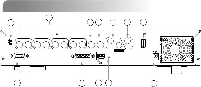
1.5 REAR PANEL
Model 1
2
1 |
3 |
4 |
5 |
6 |
12 |
LOOP |
INPUT |
LOOP |
INPUT |
LOOP |
INP UT |
LOOP |
INPUT |
MONIT OR |
CALL |
1 |
|
|
|
|
|
||||||||||
|
1 |
|
2 |
|
3 |
|
4 |
|
IN |
2 |
OUT |
USB |
|
|
|
|
|
|
|
|
|
|
|
|
|
|
|
LINK |
|
|
|
ACT. |
D / V |
EXTERNAL I/O |
LAN |
DC 19V |
|
|
7 |
8 |
9 |
10 |
11 |
1)75Ω / HI-IMPEDANCE:
When using Loop function, please switch to HI-IMPEDANCE. When you don’t use Loop function, please switch to 75Ω.
2)VIDEO INPUT (CHANNEL 1 - 4): Connect to video sources, such as cameras.
LOOP (CHANNEL 1 - 4): Video output.
3)MONITOR:
Connect to Main monitor.
4)CALL MONITOR:
Connect to CALL monitor. Show the channel switch display. When the alarm is triggered, the call monitor will show the image of the triggered channel for a period of time.
5)AUDIO IN (2 audio-in):
Connect to audio sources, such as cameras equipped with the audio function. When users start the recording function, the audio input will be recorded.
6)AUDIO OUT:
Connect to a monitor or speaker.
With 1 mono audio output from the same source.
7)D/V PORT (Digital Video Port): Connect to a VGA converter.
8)EXTERNAL I/O PORT:
Insert the supplied 15PIN DSUB to this port for connecting external devices (alarm input, external alarm, PTZ camera).
For detailed I/O port PIN configuration, please refer to Appendix #2.
9)LAN:
Connect to Internet by LAN cable.
10)LINK / ACT LED light:
When the Internet is activated, the LED light will be on.
11)POWER:
Connect to the supplied adapter.
12)USB:
Support USB flash drive firmware update and file backup.
6
1.5 REAR PANEL Continued…
|
|
1 |
|
|
|
2 |
|
|
|
|
3 |
4 |
5 |
6 |
|
|
|
|
|
|
|
|
|
|
|||||
75? |
1 4 |
IMPEDANCE-HI |
LOOP |
INPUT |
LOOP |
INPUT |
LOOP |
INPUT |
LOOP |
INPUT |
MONITOR |
CALL |
1 |
|
|
|
|||||||||||||
|
|
|
|
|
||||||||||
|
|
|
|
1 |
|
2 |
|
3 |
|
4 |
|
IN |
2 |
OUT |
|
|
|
|
|
|
|
|
|
|
|
|
|
LINK |
|
|
|
|
|
|
|
|
|
|
|
|
|
|
ACT. |
|
|
|
|
D / V |
|
|
|
|
|
|
EXTERNAL I/O |
LAN |
|
|
|
Model 2
12
USB |
DC 19V
7 |
8 |
9 |
10 |
11 |
1)75Ω / HI-IMPEDANCE:
When using Loop function, please switch to HI-IMPEDANCE. When you don’t use Loop function, please switch to 75Ω.
2)VIDEO INPUT (CHANNEL 1 - 4): Connect to video sources, such as cameras.
LOOP (CHANNEL 1 - 4): Video output.
3)MONITOR:
Connect to Main monitor.
4)CALL MONITOR:
Connect to CALL monitor. Show the channel switch display. When the alarm is triggered, the call monitor will show the image of the triggered channel for a period of time.
5)AUDIO IN (2 audio-in):
Connect to audio sources, such as cameras equipped with the audio function. When users start the recording function, the audio input will be recorded.
6)AUDIO OUT:
Connect to a monitor or speaker.
With 1 mono audio output from the same source.
7)D/V PORT (Digital Video Port): Connect to a VGA converter.
8)EXTERNAL I/O PORT:
Insert the supplied 15PIN DSUB to this port for connecting external devices (alarm input, external alarm, PTZ camera).
For detailed I/O port PIN configuration, please refer to Appendix #2.
9)LAN:
Connect to Internet by LAN cable.
10)LINK / ACT LED light:
When the Internet is activated, the LED light will be on.
11)POWER:
Connect to the supplied adapter.
12)USB:
Support USB flash drive firmware update and file backup.
7
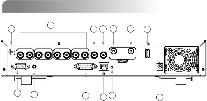
1.5 REAR PANEL Continued…
1 |
|
|
2 |
|
|
|
|
3 |
4 |
5 |
6 |
|
|
|
|
|
|
|
|||||
LOOP |
INPUT |
LOOP |
INPUT |
LOOP |
INPUT |
LOOP |
INPUT |
MONITOR |
CALL |
1 |
|
|
|
||||||||||
|
1 |
|
2 |
|
3 |
|
4 |
|
|
IN |
OUT |
|
|
|
|
|
|
|
|
|
|
LINK |
|
|
|
|
|
|
|
|
|
|
|
ACT. |
|
D / V |
|
|
|
|
|
EXTERNAL I/O |
LAN |
|
|
||
Model 3
DC 19V
7 |
8 |
9 |
10 |
11 |
1)75Ω / HI-IMPEDANCE:
When using Loop function, please switch to HI-IMPEDANCE. When you don’t use Loop function, please switch to 75Ω.
2)VIDEO INPUT (CHANNEL 1 - 4): Connect to video sources, such as cameras.
LOOP (CHANNEL 1 - 4): Video output.
3)MONITOR:
Connect to Main monitor.
4)CALL MONITOR:
Connect to CALL monitor. Show the channel switch display. When the alarm is triggered, the call monitor will show the image of the triggered channel for a period of time.
5)AUDIO IN (1 audio-in):
Connect to audio sources, such as cameras equipped with the audio function. When users start the recording function, the audio input will be recorded.
6)AUDIO OUT:
Connect to a monitor or speaker.
With 1 mono audio output from the same source.
7)D/V PORT (Digital Video Port): Connect to a VGA converter.
8)EXTERNAL I/O PORT:
Insert the supplied 15PIN DSUB to this port for connecting external devices (alarm input, external alarm, PTZ camera).
For detailed I/O port PIN configuration, please refer to Appendix #2.
9)LAN:
Connect to Internet by LAN cable.
10)LINK / ACT LED light:
When the Internet is activated, the LED light will be on
11)POWER:
Connect to the supplied adapter.
8
|
1.5 REAR PANEL Continued… |
Model 4 |
|||
1 |
2 |
4 |
5 |
6 |
12 |
3 |
|||||
LOOP INPUT LOOP INPUT LOOP INPUT LOOP INPUT MONITOR CALL
1 |
2 |
3 |
4 |
IN |
OUT |
|
USB |
||||
|
|
|
|
|
|
|
|
|
|
LINK |
|
|
IR |
|
|
ACT. |
|
D / V |
|
EXTERNAL I/O |
LAN |
DC 19V |
|
|
|
7 |
13 |
8 |
9 |
10 |
11 |
|
1)75Ω / HI-IMPEDANCE:
When using Loop function, please switch to HI-IMPEDANCE. When you don’t use Loop function, please switch to 75Ω.
2)VIDEO INPUT (CHANNEL 1 - 4): Connect to video sources, such as cameras.
LOOP (CHANNEL 1 - 4): Video output.
3)MONITOR:
Connect to Main monitor.
4)CALL MONITOR:
Connect to CALL monitor. Show the channel switch display. When the alarm is triggered, the call monitor will show the image of the triggered channel for a period of time.
5)AUDIO IN (1 audio-in):
Connect to audio sources, such as cameras equipped with the audio function. When users start the recording function, the audio input will be recorded.
6)AUDIO OUT:
Connect to a monitor or speaker.
With 1 mono audio output from the same source.
7)D/V PORT (Digital Video Port): Connect to a VGA converter.
8)EXTERNAL I/O PORT:
Insert the supplied 15PIN DSUB to this port for connecting external devices (alarm input, external alarm, PTZ camera).
For detailed I/O port PIN configuration, please refer to Appendix #2.
9)LAN:
Connect to Internet by LAN cable.
10)LINK / ACT LED light:
When the Internet is activated, the LED light will be on
11)POWER:
Connect to the supplied adapter.
12)USB:
Support USB flash drive firmware update and file backup.
13)IR PORT:
Connect the IR receiver for remote control.
9

GETTING STARTED
2.1 GETTING STARTED
Connect all the devices to construct a surveillance system.
1)Install HDD:
The HDD must be installed before the DVR is turned on. Please refer to Appendix #1 for HDD installation instructions.
2)Connect cameras, monitors and external devices. Please refer to “Section 1.5 Rear Panel” for connection, and Appendix#2 for pin configurations of the external I/O port.
NOTE:
Be sure the cameras are connected and power-supplied before the DVR is powered on. Otherwise the DVR will not be able to detect N/P system automatically.
3)Connect the AC power cord to power adapter and plug into an electrical outlet.
The “  “ or “Power” LED will be on as red.
Press the “ “ or “Power” button. The “
 “ or “Power” LED will be on as green. It takes approximately 10 to 15 seconds to boot the system.
4)Set the date and time on your DVR. Please DO NOT change the date or time on your DVR after the recording function is activated. The recorded data will be disordered and you will not be able to find the recorded file to backup by time search.
NOTE:
If users change the date or time accidentally when the recording function is activated, it’s recommended to clear all HDD data, and start recording again.
For the connection application, please see the illustration below for an example.
Take Model 1 as an example
10

BASIC OPERATION
3.1 RECORDING
The DVR offers three recording modes, manual record, event record and timer
record. If power is off accidentally, recorded video files will still be still stored in the HDD. DVR will return to the original recording status after power is on again.
1)MANUAL RECORDING (continuous recording) :
Recording is initiated by manually pressing the “REC” button, indicated by the sign “●” on the screen.
2)EVENT RECORDING (triggered by motion and external alarm) :
When this function is activated, the recording is triggered by motion or external alarms, indicated by the sign "  " (motion) or "
  " (external alarm) on the screen.
3)TIMER RECORDING (scheduled time) :
Recording is scheduled by Timer, indicated by the sign “TIMER RECORD”.
There must be at least 8192 images of recorded data for playback to work properly. If not, your DVR will stop the playback. For example, if the IPS is set to 30, the recording time should be at least 273 seconds (8192 images / 30 IPS) for the playback to work properly.
When the recording function is activated, please DO NOT change the date or time on your DVR. The recorded data will be disordered and you will not be able to find the recorded file to backup by time search.
NOTE:
If users change the date or time accidentally when the recording function is activated, it’s recommended to clear all HDD data, and start recording again.
Overwriting View
If you activate overwriting mode, you will also see “-OW-” under the recording mode except the system time, available HDD capacity, recording icon and channel title.
When the HDD is full under “-OW-” recording mode, the previous recorded files may be overwritten without further warning notice. Under “-OW-" mode, your DVR
will clear 8GB data from the oldest for overwriting once the HDD is full.
|
|
|
|
|
|
Available Capacity of |
|
|
|
|
|
|
|
|
|
|
|||
|
|
|
|
|
|
|
|
|
|
|
|
|
|
|
|
||||
|
|
|
System Time |
|
|
Internal HDD |
|
|
|
|
|
|
|
|
|
|
|||
|
|
|
|
|
|
|
|
|
|
|
|
|
|
|
|||||
|
2006-MAY-12 [FRI] 16:18:43 |
302.545 GB |
|
|
|
|
|
|
|
|
|||||||||
|
|
|
|
|
|
|
|
|
|
|
|
||||||||
|
|
|
|
|
|
|
|||||||||||||
|
|
|
|
|
|
-OW- |
|
|
|
|
|
|
|
|
|
|
|
||
|
|
|
|
|
|
|
|
|
|
|
|
|
|
|
Under HDD Overwriting |
||||
|
|
|
|
|
|
|
|
|
|
|
|
||||||||
|
|
|
|
|
|
|
|
|
|
|
|
|
|
|
|
|
Mode |
||
|
|
|
● |
● |
|
|
|
|
|||||||||||
|
|
|
|
|
|
Under Recording |
|
||||||||||||
|
|
|
|
|
|
||||||||||||||
|
|
|
|
|
|
|
|
|
|
|
|
|
|
|
|
|
|
|
|
|
|
|
|
|
|
|
|
|
|
|
|
|
|
|
|
|
|
|
|
|
|
|
|
|
|
|
|
|
|
|
|
|
|
|
|
|
Channel Title |
|
|
|
|
|
● |
● |
|
|
|||||||||||||
|
|
|
|
|
|
|
|||||||||||||
|
|
|
|
|
|
|
|
|
|
|
|
|
|
|
|
|
|||
11

3.2 PLAYBACK
Press “ ” or “PLAY” button and the DVR will display the last recorded video.
1)FAST FORWARD (F.F. ) & FAST REWIND (REW):
You can increase the speed for fast forward and rewind on the DVR. In the playback mode,
Press “►►“ once to get 4X speed forward and press twice to get 8X speed, etc., and the maximum speed is 32X.
Press “◄◄“ once to get 4X speed rewind and press twice to get 8X speed, etc., and the maximum speed is 32X.
The type of the recording image size (Frame or CIF) will also be shown on the screen.
2)PAUSE / IMAGE JOG:
Press “ 
 “ button to pause the current image displayed on the screen. In the Pause mode,
Press “►► “ once to get one frame forward.
Press “◄◄ “ once to get one frame rewind.
3)STOP:
Pressing “ ■ “ button under all circumstances will return DVR to live monitoring mode.
4)CHANNEL SHIFT:
Display mode:
Press MODE “ ” button to 4 channels display.
Full Screen Switch:
Press “1 ” “2 ” “3 ” “4 ” buttons to show the full screen channels.Channel display switch:
Press “SET” to change the the position of the channel display.
Press “▲▼◄►“ to select the channel you would like to change.
Press “ ” or “ ” to select the channel you would like show. Press “ENTER” button to confirm the setting.
5)SLOW PLAYBACK:
Model 1 & 2: Press “SLOW” button to get 1/4X speed playback and press twice to get 1/8X. Model 3: Press “SLOW” button to get 1/4X speed playback.
6)AUDIO:
SLOW |
ZOOM |
” |
Press “ |
” or “ |
AUDIO
to select either audio channel from the following 4 options:
AUDIO 1 (L) -- audio channel 1, live audio
AUDIO 1 (P) -- audio channel 1, playback audio
AUDIO 2 (L) -- audio channel 2, live audio
AUDIO 2 (P) -- audio channel 2, playback audio
12

DETAILED MENU CONFIGURATION
4.1 MENU TREE
MENU
RECORD |
|
TIMER |
|
DATE |
|
|
|
|
|
MANUAL RECORD |
DATE |
DATE: |
|
YEAR MONTH DAY |
|||
ENABLE |
|
||
|
|
||
EVENT RECORD |
START |
TIME: |
|
HH : MM |
HOUR MIN SEC |
||
ENABLE |
|||
|
|
||
TIMER RECORD |
END |
FORMAT: Y-M-D … |
|
HH : MM |
|
||
ENABLE |
|
||
|
|
||
|
|
DAYLIGHT SAVING |
|
OVERWRITE |
|
|
|
RECORD IMG SIZE |
DISPLAY |
|
|
RECORD QUALITY |
|
ALERT |
|
TITLE DISPLAY |
|
||
|
|
||
MANUAL RECORD |
DATE DISPLAY |
EXT. ALERT |
|
|
|||
IPS |
HDD INFO |
INT. BUZZER |
|
|
|||
|
|
||
EVENT RECORD |
LOSS SCREEN |
KEY BUZZER |
|
IPS |
|
||
|
|
||
TIMER RECORD |
PLAYBACK |
VLOSS BUZZER |
|
|
|||
INFO |
|
||
IPS |
MOTION BUZZER |
||
DWELL |
|||
|
|
||
TOTAL IPS SHARE |
DURATION |
ALARM BUZZER |
|
(SEC) |
|
||
|
HDD BUZZER |
||
|
|
||
|
DE- |
HDD NEARLY FULL |
|
|
INTERLACE |
||
|
(GB) |
||
|
|
||
|
MONITOR |
ALARM DURATION |
|
|
OUT |
(SEC) |
|
|
OSD |
PRE-ALARM |
|
|
WATERMARK |
NETWORK |
|
The USB backup function is only |
BACKUP |
||
for Model 1, Model 2 and Model 4. |
|
||
The disk backup function is only for |
HDD INFO |
||
Model 1. |
|
||
EVENT LOG
ADVANCE
CAMERA
DETECTION
REMOTE
SYSTEM
SERIAL TYPE
BAUD RATE
HOST ID
PASSWORD
RESET DEFAULT
CLEAR HDD
UPGRADE
AUTO KEYLOCK
LANGUAGE
VERSION
VIDEO FORMAT
TITLE
BRIG
CONT
SATU
HUE
COV
REC
TITLE
DET
AREA
LS
SS
TS
RE
ALARM
DETECTION
TIMER
TITLE
DEVICE
ID
PROTOCOL
RATE
13

4.2 MAIN MENU OPTIONS___RECORD
Press “MENU” button to enter the main menu list. The default admin password is 0000. Enter the default password and press “ENTER”. (Users could alter the password later. Please refer to “Section 4.11 ADVANCE MENU_SYSTEM”)
Move the cursor to “RECORD” and press ”ENTER”. The screen will show the following options.
(MENU)
►RECORD
TIMER
DATE
ADVANCE
Use the following buttons for menu settings:
RECORD
MANUAL RECORD ENABLE EVENT RECORD ENABLE TIMER RECORD ENABLE OVERWRITE
RECORD IMG SIZE
RECORD QUALITY MANUAL RECORD IPS EVENT RECORD IPS TIMER RECORD IPS TOTAL IPS SHARE
“▲▼◄► “ to move the cursor.
“ , ” to choose the numbers / selections.
“ENTER “ to go to the submenu / to confirm the selection
“MENU “ to go to the menu OSD /
to confirm the change / to exit the menu OSD
1)MANUAL RECORD ENABLE:
Start / stop the manual recording function.
2)EVENT RECORD ENABLE:
Start / stop the event recording function. When this function is activated, the recording will be triggered by the motion or external alarm.
3)TIMER RECORD ENABLE:
Start / stop the timer recording function.
4)OVERWRITE:
Select to overwrite previous recorded videos in HDD. When the HDD is full under O/W recording mode, previous recorded files will be overwritten without further warning notices.
5)RECORD IMG SIZE:
There are two recording options, FRAME and CIF. When changing the record image size, users need to stop recording first.
6)RECORD QUALITY:
There are four quality settings: BEST, HIGH, NORMAL & BASIC.
7)MANUAL RECORD IPS:
Recording is activated by pressing the “REC” button. Select the images per second of MANUAL RECORD, The options are as following:
NTSC: FRAME: 30, 15, 7, 3 |
PAL: FRAME: 25, 12, 6, 3 |
CIF: 120, 60, 30, 15 |
CIF: 100, 50, 25, 12 |
14

8)EVENT RECORD IPS:
Recording is activated by events (alarm and motion trigger). Select the images per second for EVENT RECORD. The options are as following:
NTSC: FRAME: 30, 15, 7, 3 |
PAL: FRAME: 25, 12, 6, 3 |
CIF: 120, 60, 30, 15 |
CIF: 100, 50, 25, 12 |
9)TIMER RECORD IPS:
Recording is activated by timer schedules. Select the images per second for TIMER RECORD. The options are as following:
NTSC: FRAME: 30, 15, 7, 3 |
PAL: FRAME: 25, 12, 6, 3 |
CIF: 120, 60, 30, 15 |
CIF: 100, 50, 25, 12 |
10)TOTAL IPS SHARE: There are two IPS settings:
FIX:
IPS per channel = RECORD IPS ÷ 4 channels
GROUP (Suitable for Frame mode):
IPS per channel = RECORD IPS ÷ number of channels under recording.
NOTE: For Model 3 & 4, the total IPS share is always “FIX”.
4.3 MAIN MENU OPTIONS___TIMER
(MENU) RECORD
► TIMER
DATE ADVANCE
Move the cursor to “TIMER” and press ”ENTER”. The screen will show the following options.
RECORD
DATE |
START |
|
END |
||
OFF |
00 |
: 00 |
- |
00 |
: 00 |
DAILY |
08 |
: 00 |
- |
18 |
: 00 |
SUN |
06 |
: 00 |
- |
23 |
: 00 |
MON-FRI |
00 |
: 00 |
- |
00 |
: 00 |
OFF |
00 |
: 00 |
- |
00 |
: 00 |
OFF |
00 |
: 00 |
- |
00 |
: 00 |
OFF |
00 |
: 00 |
- |
00 |
: 00 |
15
 Loading...