


JPEG2000 Stand alone DVR User Guide
|
CONTENTS |
|
Date: 2008/6/2 VER: 1.80 |
Caution |
……………………………………………………………………. 3 |
Package |
……………………………………………………………………. 3 |
Specification |
……………………………………………………………………. 4 |
CHAP.1 Appearance |
|
1-1 Front panel introduction |
……………………………………………………………………. 6 |
1-2 Back panel introduction |
……………………………………………………………………. 8 |
1-3 IR remote controller introduction |
……………………………………………………………………. 9 |
CHAP.2 Installation |
|
2-1 Camera and monitor installation |
……………………………………………………………………. 10 |
2-2 Sensor and alarm installation |
……………………………………………………………………. 11 |
2-3 Network and serial port installation |
……………………………………………………………………. 12 |
2-4 HDD installation |
……………………………………………………………………. 13 |
2-5 Mouse installation |
……………………………………………………………………. 14 |
2-6 Power plugging |
……………………………………………………………………. 14 |
CHAP.3 Operation |
|
3-1 Display configuration |
……………………………………………………………………. 15 |
3-2 Channel switch |
……………………………………………………………………. 16 |
3-3 PIP view |
……………………………………………………………………. 16 |
3-4 Freeze view |
……………………………………………………………………. 16 |
3-5 View in sequence |
……………………………………………………………………. 17 |
3-6 Zoom view |
……………………………………………………………………. 18 |
3-7 Keylock |
……………………………………………………………………. 18 |
3-8 switch audio channel |
……………………………………………………………………. 18 |
3-9 Record |
……………………………………………………………………. 19 |
3-10 Playback |
……………………………………………………………………. 20 |
3-11 Mouse operation |
……………………………………………………………………. 23 |
CHAP.4 Set up |
|
4-1 Log-in |
……………………………………………………………………. 25 |
4-2 Display setup |
……………………………………………………………………. 26 |
4-3 Configuration |
……………………………………………………………………. 27 |
4-4 Record setup |
……………………………………………………………………. 33 |
4-5 Bak-up |
……………………………………………………………………. 36 |
4-6 External device |
……………………………………………………………………. 38 |
4-7 Factory default |
……………………………………………………………………. 42 |
4-8 Language |
……………………………………………………………………. 42 |
- 1 -

JPEG2000 Stand alone DVR User Guide
CHAP.5 PTZ camera control
5-1 PTZ camera installation |
…………………………………………………………………… 43 |
5-2 PTZ camera operation |
…………………………………………………………………… 44 |
CHAP.6 Software installation |
|
6-1 Install Internet Relative Software |
…………………………………………………………………… 45 |
6-2 IRS operation |
…………………………………………………………………… 45 |
6-3 J2K BACKUP process |
…………………………………………………………………… 47 |
6-4 J2K PLAYER operation |
…………………………………………………………………… 48 |
6-5 H.264 transmitter |
…………………………………………………………………… 50 |
6-6 Client software operation |
…………………………………………………………………… 51 |
6-7 DDNS setup and operation |
…………………………………………………………………… 57 |
Appendix |
|
1. Record time table |
…………………………………………………………………… 59 |
2. System configuration |
…………………………………………………………………… 61 |
3. Firmware upgrade |
…………………………………………………………………… 62 |
4. Play only mode |
…………………………………………………………………… 66 |
5. Router setup |
…………………………………………………………………… 67 |
Disclaimer:
The product names mentioned in this manual are used as identifications only, while the copyright of these names might belong to other companies.
The product spec and info are for reference only, and they may be updated from time to time without notification.
- 2 -

JPEG2000 Stand alone DVR User Guide
Caution
For you safety, unplug the power before moving the DVR, installing, or replacing any parts or hard drive. Make sure all the power cable and wires are properly set up before using the DVR. Contact your distributor immediately if there is any defect.
To avoid a short circuit, don’t leave any unnecessary parts inside the DVR.
Please avoid dramatic changes of the environment, such as dust, temperature, and humidity. Keep the DVR in a temperature ranging from 5 ~40 .
Keep the DVR in a well-ventilated place and away from any heat-generating objects. Do not block the DVR’s fan and vent.
Do not expose this unit to the sun directly.
If you are not sure of the installation and setup, please consult the technicians.
If there’s any damage to this unit or the power supply, don’t fix it yourself. Consult the technician or the distributor.
Package
DVR Main unit |
× 1 |
Power Supply |
× 1 |
Power Cable |
× 1 |
Remote Controller(N TYPE) |
× 1 |
Manual |
× 1 |
Software CD-R |
× 1 |
Accessories |
× 1 |
Battery |
× 2 |
Please contact your distributor immediately if any of the above items is missing.
- 3 -

JPEG2000 Stand alone DVR User Guide
|
|
|
Specification |
|
||
|
|
|
|
|
|
|
|
Model |
|
|
|
|
|
|
|
|
|
|
|
|
|
|
Video Input |
4/8/16CH VIDEO IN 1.0 VP-P 75OHM(BNC TYPE) |
|
||
|
Video I/O |
|
|
|
|
|
|
Video Output |
(BNC TYPE) X 2 |
|
|
|
|
|
|
VGA Output |
Support TFT LCD Monitor (Optional) |
|
||
|
Audio I/O |
Audio Input |
4 CH Audio Input (MONO type) |
|
||
|
(Optional) |
|
|
|
|
|
|
Audio Output |
1 CH Audio output (MONO type) |
|
|||
|
|
|
FULL: 720(H) × 480(V) (NTSC) |
|
||
|
|
Display Resolution |
720(H) × 576(V) (PAL) |
|
||
|
|
1/4: 360(H) × 240(V) (NTSC) |
|
|||
|
|
|
|
|||
|
Monitoring |
|
360(H) × 288(V) (PAL) |
|
||
|
Split Screen |
FULL/4/6/8/9/13/16 split |
|
|||
|
Method |
|
||||
|
ZOOM IN/OUT |
Live & Playback |
|
|
|
|
|
|
|
|
|||
|
|
|
|
|
||
|
|
PIP |
Yes |
|
|
|
|
|
|
|
|
|
|
|
|
Sequence |
Yes |
|
|
|
|
|
|
FULL |
|
NTSC-720×240 / PAL-720×288 |
|
|
|
Resolution |
DUAL |
|
NTSC-360×240 / PAL-360×288 |
|
|
|
|
QUAD |
|
NTSC-360×120 / PAL-360×144 |
|
|
|
|
|
|
|
|
|
|
|
FULL |
|
4CH: NTSC-60IPS/ PAL-50IPS |
|
|
|
|
|
8/16CH: NTSC-120IPS/ PAL-100IPS |
|
|
|
|
|
|
|
|
|
|
|
Frame Rate |
DUAL |
|
4CH: NTSC-120IPS/ PAL-100IPS |
|
|
|
|
8/16CH: NTSC-240IPS/ PAL-200IPS |
|
||
|
|
|
|
|
|
|
|
|
|
QUAD |
|
4CH: NTSC-240IPS/ PAL-200IPS |
|
|
Record |
|
|
8/16CH: NTSC-480IPS/ PAL-400IPS |
|
|
|
|
|
|
|
||
|
Compression |
JPEG2000 |
|
|
||
|
Playback |
|
|
|
||
|
|
LOW |
|
NTSC (12 KB/720×240)/PAL(14 KB/720×288) |
|
|
|
|
|
|
|
||
|
|
|
MID |
|
NTSC (16 KB/720×240)/PAL(19 KB/720×288) |
|
|
|
Quality |
HIGH |
|
NTSC (20 KB/720×240)/PAL(24 KB/720×288) |
|
|
|
|
SUPER |
|
NTSC (24 KB/720×240)/PAL(29 KB/720×288) |
|
|
|
|
HYPER |
|
NTSC (28 KB/720×240)/PAL(32 KB/720×288) |
|
|
|
|
|
|
|
|
|
|
Storage Device |
SATA HDD |
|
|
|
|
|
|
|
|
|
|
|
Record Audio |
Bit rate |
NTSC: 120kb/sec |
PAL: 100kb/sec |
|
|
|
|
|
|
|
|
|
- 4 -

JPEG2000 Stand alone DVR User Guide
|
|
|
|
|
Record Mode |
Real time/ motion /alarm /schedule |
|
|
Search |
Percentage/ Time & Date /Event |
|
Playback |
Shuttle Jog |
For Easy Search |
|
Fast Forward |
x2, x4, x16, x32, x60(NTSC) |
||
Method |
|||
Fast Rewird |
x2, x4, x15, x25, x50(PAL) |
||
|
|||
|
|
|
|
|
Slow Forward/Reward |
1/2,1/4,1/8,1/16 |
|
|
Picture by Picture |
Available |
|
|
Protocol |
TCP/IP |
|
Network |
Remote monitoring |
Remote Softeware: Remote live view, playback, and save as AVI |
|
IE: Remote live view, backup, and save backup to AVI |
|||
|
Users |
||
|
Two users access is available. |
||
Back-up |
Back-up method |
VCR, Backup via IE ,CD-R back-up(Include CD Backup player),USB |
|
backup |
|||
|
|
||
|
PTZ Control |
RS485 supports PELCO D and other protocols |
|
|
RS232 |
Controls DVR host through RS232 |
|
|
|
4CH: 4 Alarm Inputs |
|
|
|
||
|
Alarm Input |
8CH: 8 Alarm Inputs |
|
|
|
16CH: 16 Alarm Inputs |
|
|
Alarm Output |
1(Programmable alarm output duration) |
|
|
Remote Controller |
Infrared Remote Controller |
|
|
Control Device |
Front Panel, Remote Controller, RS232 |
|
|
|||
|
Multi-language |
English/Spanish/German/France/Chinese… |
|
|
HDD |
1or2 HDDs, (160Gb or above ) |
|
|
Temperature |
41°F~104°F (5°C~40°C) |
|
|
Humidity |
Under 90% |
|
Mechanism |
Dimension |
430mm(W) x 400mm(D) x 92mm(H) |
|
|
Weight |
8 KG (w/o HDD) |
|
|
|||
|
Power |
Switching Power (DC 12V, 6.67Amp) |
|
|
|
|
- 5 -

JPEG2000 Stand alone DVR User Guide
CHAP.1 Appearance
1-1 Front panel introduction
1.[CD-RW]
Built-in CD-RW for CD back-up.
2.[USB Port]
DEVICE:Connect PC for firmware upgrade. HOST: Connect USB memory stick for backup.
3.[IR Receiver & LED Lamps]
IR Remote Controller Receiver. DVR Status LED:
RUNFlashes when play picture by picture through J. Shuttle. ACTIVEOn when the J. Shuttle is ready to use.
RECOn while recording and flashes at stand-by mode, such as no motion triggered at the motion record mode PLAYOn while playback.
FULLOn when HDD storage is full.
NETOn when the DVR is connected remotely.
4.[1~16 Channel Button]
Switch full screen among channels, 1 for Channel 1, 2 for Channel 2, and so on.
5.[MODE]
Switch among full and split screen displays.
6.[K.LOCK]
Lock the buttons on front panel.
7.[MENU]
Enter the menu and set up.
8.[Directions & ENTER]
DirectionsNavigate the menu. ENTERConfirm the selected options.
9.[Jog Shuttle]
In playback: inner rim to play picture by picture, outer rim to play fast forward and backward. Turn clockwise to play fast forward, and counterclockwise to play fast backward.
Turn the Jog Shuttle to change values in system set-up.
- 6 -

JPEG2000 Stand alone DVR User Guide
10.[PTZ]
Press [PTZ] to enter the PTZ control mode. Press the PTZ buttons to control the PTZ camera directly.
11.[+ / -]
Adjust set-up value.
Adjust display orders of channel.
12.[Control]
SEQ/AUDIOPress quickly for AUDIO, and press and hold for 3 seconds to enter SEQ mode. SEQ -Full screen sequencing or the smaller screen sequencing in PIP mode.
AUDIOPress to play the audio, and press again to go to the next audio channel. PIPTo enter the Picture in Picture mode from full screen mode.
NEXTGo to the next PTZ command in PTZ mode.
Go to the next channel in full screen display and the next page in split screen display. ZOOMTo enlarge the picture. Use the direction buttons and move to the area to be enlarged.
13.[REC]
To activate Emergency Record at continuous, Super fine quality and Best resolution. Press STOP to exit the Emergency Record mode.
14.[STOP]
Stop the emergency record and return to the record schedule programmed in the Record Setup. Stop playback and return to the LIVE mode.
15.[SEARCH]
Enter the Search dialog window to search by percentage, date / time, or the event list.
16.[PLAY]
Play the recorded video beginning from the end of previous playback.
17.[FREEZE]
Freeze in full screen or split screen
18.[J.SHUTTLE Button]
Activate the Jog Shuttle and press again to deactivate
- 7 -

JPEG2000 Stand alone DVR User Guide
1-2 Back panel introduction
[4Channel]
[8Channel]
[16Channel]
1.[RS485, Relay Output, Sensor Input]
RS485, for connection to PTZ cameras. 16 sensor inputs and 1 relay output.
2.[VGA Output]
Connection to a VGA monitor or TFT LCD.
3.[ETHERNET]
Connection to Ethernet device.
4.[RS-232C]
Connection to PC or other DVR control devices.
5.[1~16 Camera Input/LOOP Output]
CAMERA INchannel 1~16 camera input. LOOPchannel 1~16 camera loop out
6.[Monitor / SPOT Output]
MONITORConnection to monitor.
SPOTsecond monitor output. Once alarm or motion is triggered, it will pop up automatically or display in sequence according to the set up.
7.[Power Input]
DC power input (DC12V)
8.[Power Switch]
Power ON/OFF
9.[Audio Input/Output]
Audio input 1~4 channel and Audio output 1 channel.
10.[P/S2 mouse]
For PS/2 Mouse connection.
- 8 -

JPEG2000 Stand alone DVR User Guide
1-3 IR remote controller introduction
1.[MENU]
Enter menu or exit
2.[Split /OSD]
4S: 4 split 9S: 9 split
16S: 16 split
AUDIO: Press to play the audio, and press again to go to the next audio channel.
3.[1~16 Channel]
Switch channel in live or playback; password entering
4.[Control function]
FRZFreeze the screen in display SEQAutomatically display full screen or split screen in sequence
ZOOMTo enlarge the picture. Use the direction buttons and move to the area to be enlarged.
PIPPicture in Picture. Enter PIP mode in full screen
5.[Mode/PT]
MODE- Multi-screen display selection P/T- Enter the PTZ camera control mode
6.[SEARCH/-/+/NEXT]
SEARCHOpen the search window in playback
[-]/[+]- For value adjustment in set-up NEXTGo to the next PTZ command in PTZ mode.
Go to the next channel in full screen display and the next page in split screen display
7.[Rec]
To activate Emergency Record at continuous, Super fine quality and Best resolution.
8.[Stop]
Stop the emergency recordand return to the record schedule programmed in the Record Setup. Stop playback and return to the LIVE mode.
9.[Functions]
PLAYPlay the recorded video directly. PAUSEPause playback.
REWFast rewind, press again to select the speed. FFFast forward, press again to select the speed. STEPPlay picture by picture.
SLOWSlow motion playback, press again to select the speed.
10.[ENTER]
Select or adjust options in setup.
11.[Direction]
Navigate the menu.
- 9 -
JPEG2000 Stand alone DVR User Guide
CHAP.2 Installation
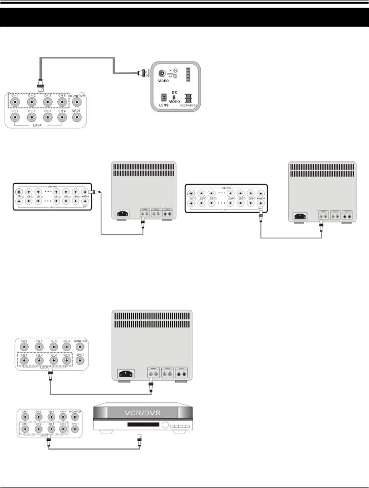
2-1 Camera and monitor installation
2-1-1 Camera installation
Connect camera to DVR camera in CH1~CH16
Please do not start the DVR before the camera. installation is done.
2-1-2 Monitor and SPOT installation
Monitor: Connect the MONTIOR port on the DVR back panel to the “video in” port on the monitor.
SPOT: second monitor output. Once alarm or motion is triggered, it will pop up automatically or display in sequence according to the set up.
2-1-3 Loop out installation
To monitor a single channel, connect the “loop out” of the corresponding channel to a monitor.
To record a specific channel individually, connect the “loop out” of the corresponding channel to a DVR, VCR, or other record device.
- 10 -

JPEG2000 Stand alone DVR User Guide
2-2 Sensor and alarm installation
2-2-1 Input & Output
[4Channel]
[8Channel]
[16Channel]
1.[D1~D16 Alarm Input/GND for Location]
16 Sensor inputs, for sensor input installation.
2.[Relay Output NO/NC/COM]
The application of relay output is NO+COM + NC+COM.
2-2-2 Sensor installation
Alarm will be triggered once one (or more than one) alarm input (D1~D16) causes short circuit or open circuit with GND.
2-2-3 Relay output installation
Alarm output can be NO or NC, depending on the settings.
NO-COM: the NO and COM terminals are open-circuit, and it’ll become closed-circuit when alarm triggered. NC-COM: the NC and COM terminals are closed-circuit, and it’ll become open-circuit when alarm triggered.
- 11 -

JPEG2000 Stand alone DVR User Guide
2-3 Network and serial port installation
2-3-1 Network setup
Connect the network cable to “Ethernet”on back panel.
Ethernet Setup between ADSL and Cable is different.
2-3-2 Serial port setup
User is able to connect the COM port of PC or other device to the DVR through RS232.
RS232 settings (baudrate/ parity/ length/ stop bit ) are NOT adjustable.
The transmission baudrate is 19200bps, length 8 bits, stop bit 1, and the parity is none.
ASCII-CODE is 1 BYTE.
|
|
connector |
|
description |
|
|
|
|
|
|
|
|
|
|
|
|
|
|
|
|
|
|
|
|
|
|
|
|
|
|
|
|
|||||||
|
|
1 |
|
|
DCD |
|
Func. CODE |
Func. CODE |
Func. CODE |
Func. CODE |
Func. CODE |
||||||||
|
|
2 |
|
|
RxD |
|
REC |
R |
RIGHT |
K |
MODE |
D |
CH3 |
3 |
|
CH11 |
! |
||
|
|
|
|
|
|
||||||||||||||
|
3 |
|
|
TxD |
|
STOP |
S |
NEXT |
N |
|
PIP |
I |
CH4 |
4 |
|
CH12 |
@ |
||
|
|
4 |
|
|
DTR |
|
PLAY |
P |
ENTER |
0X0D |
|
SEQ |
Q |
CH5 |
5 |
|
CH13 |
# |
|
|
5 |
|
|
GND |
|
SEARCH |
E |
- |
< |
|
J.SHU |
L |
CH6 |
6 |
|
CH14 |
$ |
||
|
|
|
|
|
|
|
|||||||||||||
|
6 |
|
|
DSR |
|
MENU |
M |
+ |
> |
|
KLOCK |
C |
CH7 |
7 |
|
CH15 |
% |
||
|
|
7 |
|
|
RTS |
|
UP |
U |
PTZ |
T |
QPLAY |
Y |
CH8 |
8 |
|
CH16 |
^ |
||
|
8 |
|
|
CTS |
|
DOWN |
J |
ZOOM |
Z |
|
CH1 |
1 |
CH9 |
9 |
|
|
|
||
|
|
|
|
|
|
|
|
|
|||||||||||
|
9 |
|
|
NC |
|
LEFT |
H |
FRZ |
F |
|
|
CH2 |
2 |
CH10 |
0 |
|
|
|
|
|
|
|
|
|
|
|
|
|
|
||||||||||
To connect DVR to a PC, users must use a twisted RS232 cable, as the illustration. |
|
|
|
|
|||||||||||||||
|
|
|
|
|
|
|
|
|
|
|
|
|
|
|
|
|
|
|
|
|
DVMR unit |
|
|
|
Other device (PC) |
|
|
|
|
|
|
|
|
||||||
D-SUB 9 cable (twisted RS-232C cable)
# 2 |
RxD |
|
|
|
RxD |
# 2 |
|
|
|
|
|
|
|
|
|
|
|
|
|
|
# 3 |
TxD |
|
|
|
TxD |
# 3 |
|
|
|
|
|
|
|
|
|
|
|
|
|
|
# 5 |
GND |
|
|
|
GND |
# 5 |
|
|
|
||||
|
|
|
|
|
|
|
- 12 -
JPEG2000 Stand alone DVR User Guide
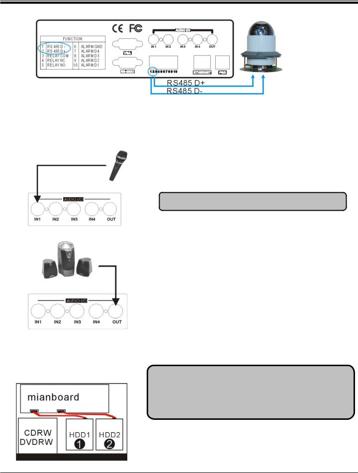
2-3-3 PTZ camera installation
Please connect the PTZ’s D+ to the DVR’s D+ , and D- to D-.
After the connection and the related setup is done, users are able to control the PTZ camera through the front panel buttons.
2-3-4 Microphone and Speaker installation [Audio input]
IN1~IN4: 4 audio inputs.
MIC to the audio input (IN1~IN4) to record audio.
Tip: Use an Amplifier to obtain a better sound recording.
[Audio output]
Connect a speaker to the audio output, DVR can play the audio during the live view and playback.
2-4 HDD installation
[Steps]
1. Disassemble the bolts as illustrated. 2.HDD Installation
1.Power off the DVR before HDD installation.
2.Suggested HDD spec & Brand: SATA HDD (Maxtor /Hitachi /
Seagate)
3. HDD storage 400GB (or above) is supported.
Please insert the first HDD as shown in ,insert the second HDD as shown in .
- 13 -

JPEG2000 Stand alone DVR User Guide
2-5 Mouse installation
PS/2 port in back panel
2-6 Power plugging
Insert the adapter to the rear power socket of DVR. Insert the power cable to the other side of adapter.
Plug in the power cable and power on the
DVR.
Caution !
Only the original supplied power adaptor is allowed.
- 14 -
JPEG2000 Stand alone DVR User Guide
CHAP.3 Operation
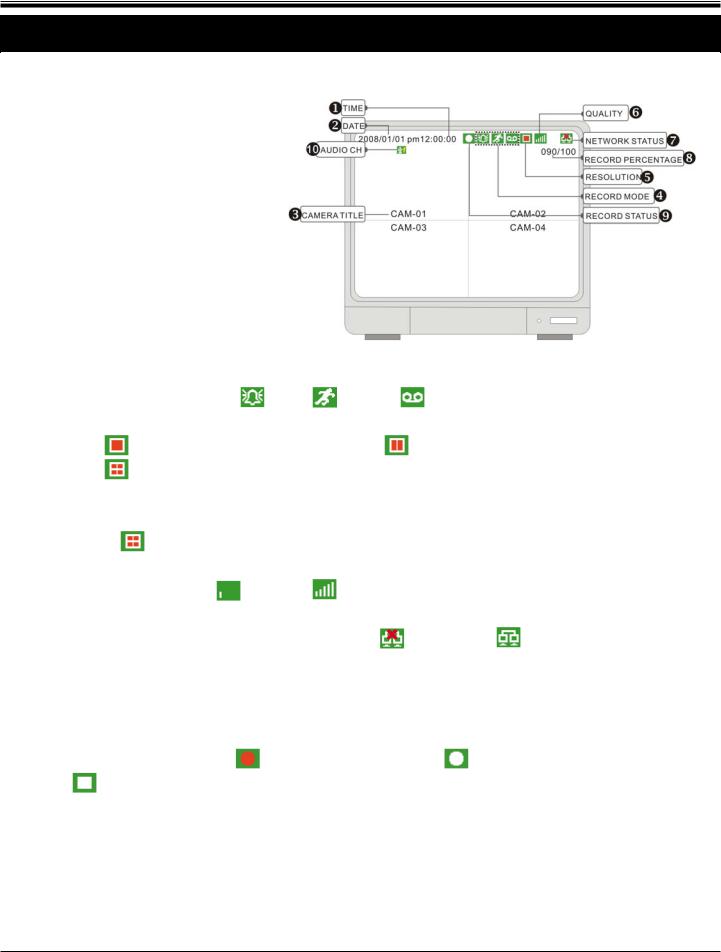
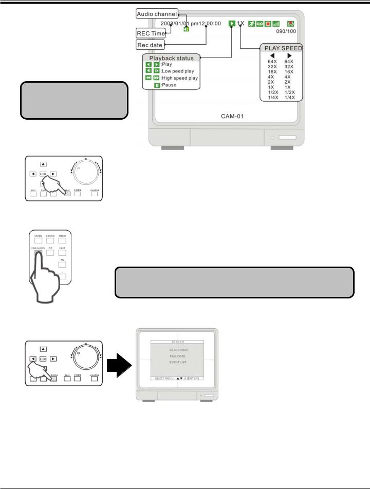
3-1 Display configuration
1.[Time]
Current system time or the recorded time in playback
2.[Date]
Current system date or the recorded date in playback
3.[Camera title]
Camera title of the displayed channel. Camera title can be modified in
[SYSTEM MENU]f[CONFIGURATION]f[CAMERA SETUP] f [CAMERA TITLE]. .
4.[Record mode]
The current recording mode |
alarm |
motion |
continuous |
|
5.[Record resolution] |
|
|
|
|
4CH: |
50IPS@720X288/60IPS@720X240 |
100IPS@360X288/120IPS@360X240 |
||
|
200IPS@360X144/480IPS@360X120 |
|
||
8/16CH:  50IPS@720X288/60IPS@720X240
  100IPS@360X288/120IPS@360X240
200IPS@360X144/480IPS@360X120
6.[Quality]
To show record quality |
LOW ~ |
HYPER |
7.[Network LED]
To show if there is a client connected.. Disconnected |
Connected |
8.[HDD record/search percentage]
In LIVE mode, the number means the HDD space used for record.
In Playback mode, the number means the percentage of the data played.
9.[Record status]
To show the record status |
Emergency record(Red) |
scheduled record (White) |
Stop record |
|
|
10.[Audio output channel]
Indicate the Audio output channel.
- 15 -
JPEG2000 Stand alone DVR User Guide
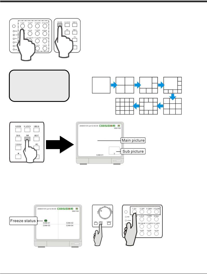
3-2 Channel selection
Split mode: 4CH: 1 / 4
8CH: 1 / 4 / 6 / 8 / 9
16CH: 1 / 4 /6 / 8 / 9 / 13 / 16
3-3 PIP view
Press the number button to switch to the corresponding channel for its full screen view
Mode: press to switch among different split modes: 4/6/8/9/13/16 splits.
+/-: button to adjust the order.
When you playback video which recorded in 360X240(360X288) resolution, only 1, 4, 9, 13 & 16 split screens are available. When you playback video which recorded in 360X120(360X144) resolution,only 1, 4 & 16 split screens are available.
In full screen mode, press “PIP” to enter PIP mode.
Press “PIP” again to cancel.
3-4 Freeze view
3-4-1 Freeze in split mode
In a split screen mode, press FREEZE and press a number button to select the corresponding channel to freeze. Press the number again to cancel freeze.
- 16 -

JPEG2000 Stand alone DVR User Guide
3-4-2 Freeze in Full mode
In full screen mode, Press FREEZE to freeze the channel, and press FREEZE again to cancel.
3-5 View in sequence
Sequence is only functional in full screen.
Keep pressing SEQ for 2~3 seconds and enter sequence mode, keep pressing SEQ for 2~3 seconds again to cancel it.
Sequence order A B C D … A B …
Sequence time is adjustable in system setup. Please see [SYSTEM MENU]f [CONFIGURATION]f [INTERVAL SETUP] for details.
- 17 -

JPEG2000 Stand alone DVR User Guide
3-6 Zoom in view
Go to the channel to be zoomed and press ZOOM to enlarge to 200%, use direction buttons to move the enlarged part.
Use the direction buttons to choose an area and press ENTER to zoom. Press ZOOM again to cancel
3-7 Key lock
After pressing “K. LOCK “, you’ll see LOCK on screen and no button is fucntioning at this time. To unlock, press and hold K.LOCK and enter Admin’spassword.
Please note that rebooting the DVR can not deactivate K.LOCK. You must enter ADMIN’s password to unlock the keys.
3-8 Selection Audio Channel
Press AUDIO you’ll see,  . The number indicates the current audio output channel.
To go the next audio channel, press AUDIO again. Press Once to play channel 1; press twice to play channel 2; press three times to play channel 3; press four times to play channel 4 and five times to turn Audio OFF.
- 18 -

JPEG2000 Stand alone DVR User Guide
3-9 Record
 Emergency record (Red): press REC to start emgergency record at continuous record mode and at the best resolution and quality.
 Schedule record (White): record at the setup schedule, record mode, resolution and quality
 Stop record : the white dot shows up when the record schedule is set to “not record” at this time. Record mode mark:
Alarm record: DVR records when the alarm is triggered
Motion record: DVR records when motion is detected
Continuous record: DVR records continuously
If the power is cut off unexpectedly, the DVR will automatically resume its recording schedule after the power is back.
Regarding record mode setup, please refer to the RECORD SETUP.
[Record percentage]
090/100 Entire HDD storage percentage
data recorded percentage
The number means the percentage of the hard drive space used for recording data.
Under the following circumstances, the system stops recording:
1.when the DVR enters the menu 2.No video inputs.
3.When all cameras are set to record off.
4.No motion is detected while the record mode is set to MOTION. 5.When the record schedule is set to Not Record.
6.Without clearing HDD or running factory defaults after a new HDD is installed.
7. When the DVR enters the Search dialog window. The DVR, if set to Triplex Mode, resumes recording as soon as it enters playback.
Besides the above circumstances, the DVR, if set to Duplex Mode, stops recording when the DVR enters Playback locally or remotely. Please see RECORD SETUP for DUPLEX and TRIPLEX setup details.
- 19 -
JPEG2000 Stand alone DVR User Guide
3-10 Playback
Play and search must inuput password.
3-10-1 Play/Stop
Press PLAY key on front panel to start playback starting from the last playback time.
Press“ PLAY ”during playback to choose to play forward or backward. Press“ STOP ”key to stop playback.
3-10-2 Switch to Audio Channel
Press “SEQ/AUDIO” to switch to other audio channels
Pon OSD you’ll see  , the number represents audio output channel
Audio output and channel are not corresponding, they can be selected separately.
3-10-3 Search mode
Press SEARCH key to open the search dialog window. There are 3 modes for search: SEARCH BAR, TIME/DATE, EVENT LIST.
1.[SEARCH BAR]
Search by appointing a recording percentage. Using Jog-shuttle is a quick and convenient way to search.
2.[TIME/DATE]
Search by appointing a time and date
3.[EVENT LIST]
Search by Event list.
- 20 -
JPEG2000 Stand alone DVR User Guide
3-10-4 SEARCH BAR
Using Jog-shuttle or +/- keys to select the recording percentage of the search bar. Press “ ENTER ”key to confirm and start the playback.
3-10-5 TIME/DATE
1.[START] The start time and date of recording
It shows that the start time and date of the recording data. 2.[END] The end time and date of recording
It shows that the end time and date of the recording data.
Input the appointed time and date to start playback.
Select the time and date by +/- key to adjust numbers and by ef key to adjust the cursor position. Then press “ Enter ”to start playback.
3-10-6 EVENT LIST
CHshows the channel in which the event happened
EVENTshows the type of events: Motion detection (MOT), Image lost (LOS), Alarm trigger(ALM). TIME/DATEshows the event time and date.
DVR keeps up to 1000 events in itsEVENT LIST.
Using key to select events and +/- key to change pages.
- 21 -
 Loading...