

Page 1

Versatile H.264 DVR
OSD Setup Manual
Version 1.4
79080EA04
Page 2

OSD Setup Manual
Table of Contents
Menu System Overview.....................................................................................................6
< Username and Password >....................................................................................6
< Key Usage > ..........................................................................................................7
Γ Key Usage in OSD Menu ...............................................................................7
Γ Key Usage in Virtual Keyboard.......................................................................7
System Setup .....................................................................................................................9
< System/Version Info > ............................................................................................9
Γ Model Name ...................................................................................................9
Γ Video System .................................................................................................9
Γ Hardware........................................................................................................9
Γ Software .........................................................................................................9
Γ MAC Address 1 ............................................................................................10
Γ Software Upgrade Via Local Device.............................................................10
Γ Software Upgrade Via Internet .....................................................................10
< Language >.......................................................................................................... 11
< Date/Time > ......................................................................................................... 11
Γ Date / Time................................................................................................... 11
Γ Time Zone ....................................................................................................12
Γ Date/Time Display ........................................................................................12
Γ Date Display Mode .......................................................................................12
Γ Time Display Mode.......................................................................................12
Γ Date/Time Order...........................................................................................13
Γ Daylight Saving Time Setup .........................................................................13
- Daylight Saving Time ......................................................................13
- DST Start / End ...............................................................................13
- DST Bias.........................................................................................13
Γ Network Time Protocol Setup .......................................................................13
- NTP Server .....................................................................................14
- Automatically Time Sync.................................................................14
- Manually Time Sync........................................................................14
< Unit Name >.........................................................................................................14
< User Management > ............................................................................................15
Γ Password Protection ....................................................................................15
Γ Account Setup ..............................................................................................15
Γ Authority Setup.............................................................................................16
Γ Load Default Setting.....................................................................................16
< Network Setup > ..................................................................................................17
Γ LAN Select ...................................................................................................17
1
Page 3

OSD Setup Manual
Γ LAN Setup ....................................................................................................17
Γ Trigger Port ..................................................................................................20
Γ Email Address ..............................................................................................20
Γ SMTP Setup .................................................................................................21
- DHCP..............................................................................................18
- IP ....................................................................................................18
- Netmask..........................................................................................18
- Gateway..........................................................................................18
- DNS ................................................................................................19
- PPPoE Account...............................................................................19
- PPPoE Password............................................................................20
- PPPoE Max Idle..............................................................................20
- Connect At Booting .........................................................................20
- Network Restart ..............................................................................20
- Email Via SMTP..............................................................................21
- SMTP Server ..................................................................................21
- SMTP Port ......................................................................................22
- SMTP Account ................................................................................22
- SMTP Password .............................................................................22
Γ DDNS Setup.................................................................................................22
- Enable DDNS..................................................................................23
- Host Name ......................................................................................23
- DDNS Port ......................................................................................23
- Submit/Update ................................................................................24
- ezDDNS..........................................................................................24
< RS485 Setup >.....................................................................................................24
Γ Unit ID ..........................................................................................................24
Γ Baud Rate ....................................................................................................24
Γ Bits ...............................................................................................................25
Γ Stop..............................................................................................................25
Γ Parity ............................................................................................................25
< Audio Output/Key Beep >.....................................................................................25
Γ Audio Output ................................................................................................25
Γ Key Beep......................................................................................................25
Γ Split Mode Audio...........................................................................................25
<IP Camera Support> .............................................................................................26
Monitor Setup...................................................................................................................27
< Show Camera Title >............................................................................................27
< Screen Center Adjust >........................................................................................27
< VGA Resolution >.................................................................................................27
2
Page 4

OSD Setup Manual
< Show Color Bar >.................................................................................................27
Camera Setup...................................................................................................................28
< Analog Camera > .................................................................................................28
Γ Analog Camera Select .................................................................................28
Γ Dome Protocol..............................................................................................28
Γ Dome ID .......................................................................................................28
Γ Camera Title.................................................................................................28
Γ Covert...........................................................................................................29
Γ Brightness ....................................................................................................29
Γ Contrast........................................................................................................29
Γ Saturation.....................................................................................................29
Γ Hue...............................................................................................................29
<IP Camera>...........................................................................................................30
Γ IP Camera Select .........................................................................................30
Γ IP Camera Title.............................................................................................30
Γ Hostname/IP.................................................................................................31
Γ Model ...........................................................................................................31
Γ Connection Setup.........................................................................................31
- Account ...........................................................................................31
- Password ........................................................................................31
- Management Port ...........................................................................31
- Streaming Format ...........................................................................31
- Advance Streaming Options............................................................31
- Streaming Port ................................................................................32
- Streaming Protocol..........................................................................32
- IP Dome Protocol............................................................................32
Γ Device Setup ................................................................................................32
- Product ID.......................................................................................33
- Image Resolution/ FPS/ Compression/ Quality ...............................33
- Sharpness/ Brightness/ Contrast/ Saturation/ Hue..........................33
- Apply...............................................................................................33
Γ Activated.......................................................................................................34
Γ Status ...........................................................................................................34
Record Setup ...................................................................................................................35
< Record Mode Setup > ..........................................................................................35
Γ Record Resolution........................................................................................35
Γ Record Format .............................................................................................35
Γ Max Rec. PPS ..............................................................................................36
Γ CBR/VBR .....................................................................................................36
< Schedule Setup >.................................................................................................36
3
Page 5

OSD Setup Manual
Γ Day / NightʳTime Start / End .........................................................................36
Γ Weekend Schedule ......................................................................................37
Γ Weekend Startʳ/ End.....................................................................................37
< Preset Record Configuration >.............................................................................37
< Per Camera Config > ...........................................................................................38
Γ Camera Select..............................................................................................38
Γ Normal PPS..................................................................................................38
Γ Normal Qlty ..................................................................................................38
Γ Event Max PPS ............................................................................................38
Γ Event Qlty.....................................................................................................39
Γ Event Active..................................................................................................39
< ezRecord Setup > ................................................................................................39
< Data Lifetime >.....................................................................................................40
< Circular Recording > ............................................................................................40
< Audio Recording >................................................................................................40
< Purge Data >........................................................................................................41
Γ Purge All Data ..............................................................................................41
Γ Purge All Event Data ....................................................................................41
Γ Purge Event Before ......................................................................................41
Γ Start To Purge...............................................................................................41
Sequence Setup...............................................................................................................42
< Main / Call Monitor Dwell > ..................................................................................42
< Main / Call Monitor Schedule > ............................................................................42
Event Setup ......................................................................................................................43
< Internal Buzzer >..................................................................................................43
< Event Icon >.........................................................................................................43
< Email Notice >......................................................................................................43
< Email Attachment > ..............................................................................................44
< Event Full Screen >..............................................................................................44
< Event Duration > ..................................................................................................44
< Per Channel Config >...........................................................................................44
Γ Channel Select .............................................................................................44
Γ Video Loss Detect ........................................................................................45
4
Γ Motion Detect ...............................................................................................45
Γ Motion Detect Indicator ................................................................................45
Γ Detection Config...........................................................................................45
- Detected Area Setup.......................................................................45
- Sensitivity........................................................................................46
- Block Threshold ..............................................................................46
Γ Alarm In........................................................................................................46
Page 6

OSD Setup Manual
Γ Alarm Out .....................................................................................................46
Database Setup................................................................................................................47
< Total / Free Size > ................................................................................................47
< Avail. Rec Time > .................................................................................................47
< Internal Disks > ....................................................................................................47
Configuration ...................................................................................................................49
< Load Factory Default >.........................................................................................49
< Import Config > ....................................................................................................49
< Export Config > ....................................................................................................50
Γ Copy Destination ..........................................................................................50
Γ Config Name ................................................................................................50
Γ Begin Export.................................................................................................50
Shutdown .........................................................................................................................51
< Power Off >..........................................................................................................51
< Reboot > ..............................................................................................................51
Appendix A: ezRecord Diagram Samples......................................................................52
Appendix B: Record Duration.........................................................................................55
Appendix C: DVRPlayer ..................................................................................................58
Appendix D: Operating USB Mouse on the DVR...........................................................63
Appendix E: HDD Copy Tool (EXT2IFS) .........................................................................64
5
Page 7
OSD Setup Manual
ʳ ʳ ʳ
Menu System Overview
The detailed functions and settings of Versatile H.264 DVR can be set by entering the
intuitive Graphical User Interface (GUI) OSD setup menu. Collaborating with a USB mouse,
setting up the DVR can be easy as operating on a PC. This chapter particularizes the items
and options in the OSD setup menu.
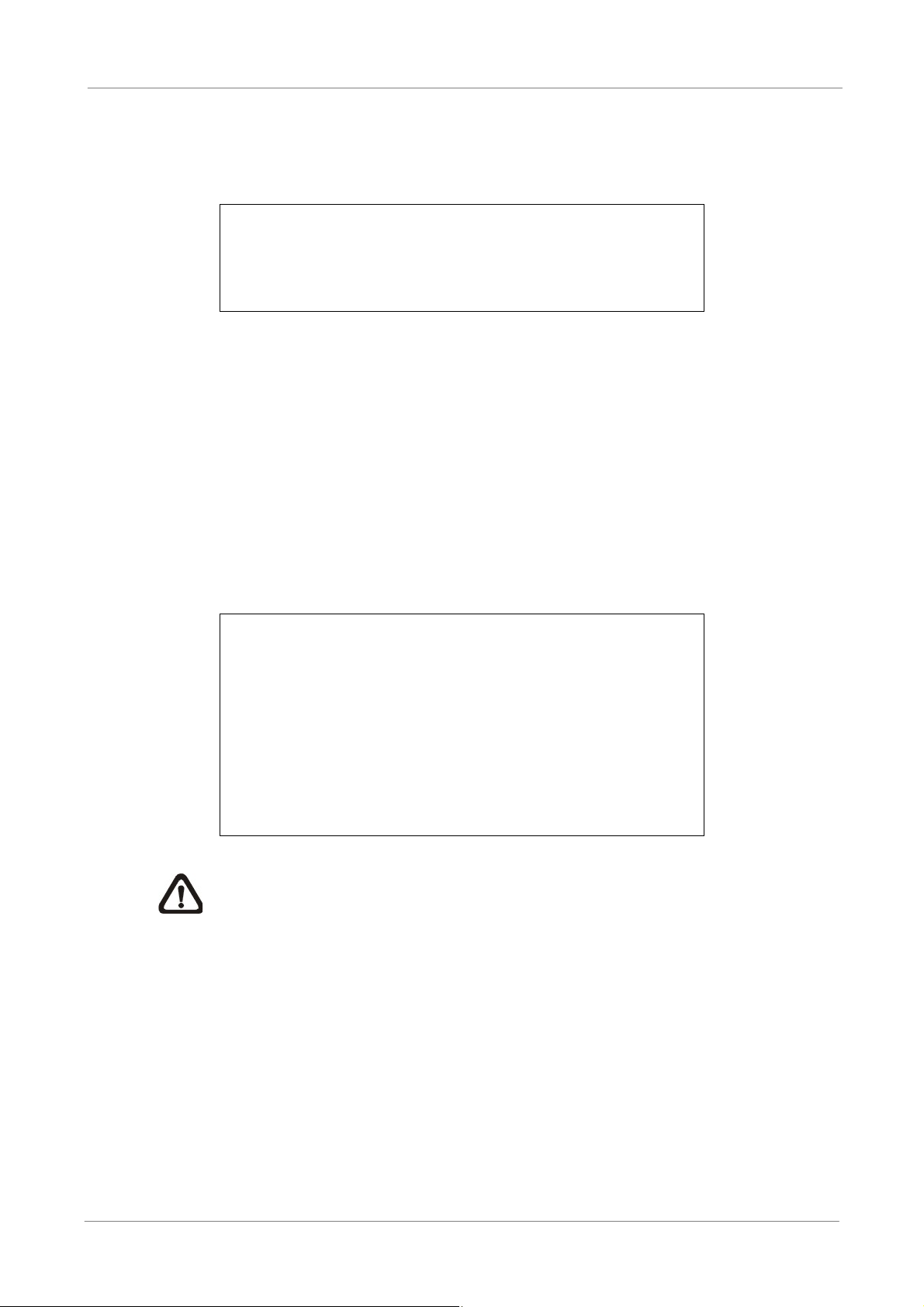
< Username and Password >
Press MENU and input a valid username. There are two preset accounts: “admin” and
“user”. The default username “admin” can be inputted via pressing the hot key MENU, while
“user” can be inputted via pressing the hot key SEARCH. Move to <OK> and press ENTER
to proceed.
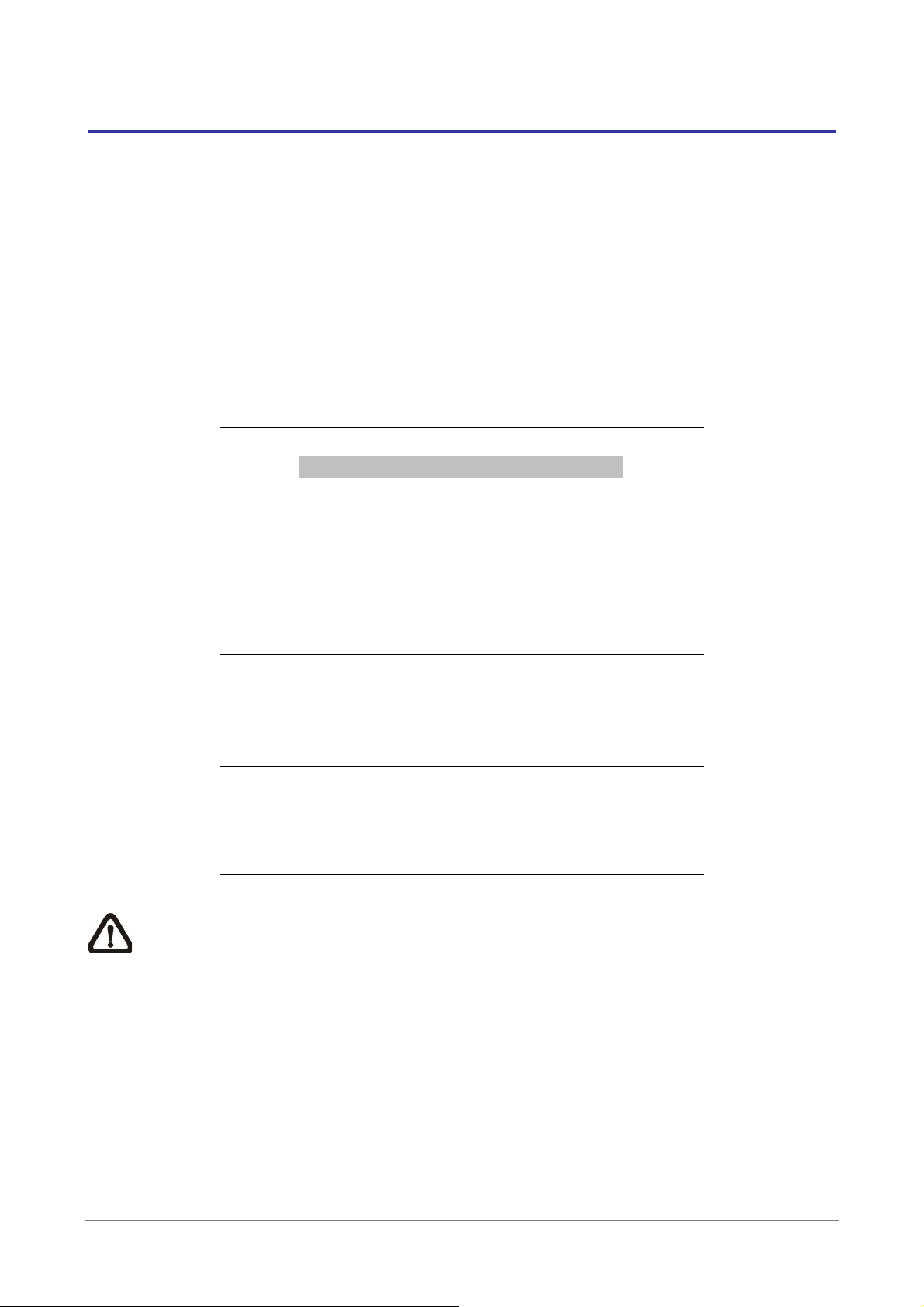
Input Username
A B C D E F G H I J K L M
N O P QRSTUVWXYZ
a b c d e f g h i j k l m
n o p q r s t u v w x y z
0 1 2 3 4 5 6 7 8 9 . ! @
# _ , “ + = *
Backspace Delete
Cancel OK
The next step is to enter a corresponding password. The preset password for “admin” is
“1234”, and the password “4321” is for “user”.
Password Verification
____________
Press Channel Keys To Enter Password
(4-8 Digits)
Press Key To Delete
NOTE: It is strongly suggested to change the preset password to prevent
unauthorized access to the DVR.
An icon displayed at the upper-right corner of the screen will show the authority level of the
account. Under logout condition, the icon will show “N”. When an account is logged in, its
authority level number (1~8) will be shown.
Before completely logout, other functions can also be accessed without having to login
again. There are two ways to logout: manually logout by pressing ESC key at Live mode, or
auto logout after 5 minutes idle time at Live/ Menu mode.
6
Page 8

OSD Setup Manual
< Key Usage >
The key usage differs under the OSD menu and in the Virtual keyboard. The difference can
be seen while setting some items, such as DVR Name and IP Address.
Key Usage in OSD Menu
The following introduce some keys used frequently to setup the DVR via the OSD
menu.
<Direction Keys>
In the OSD menu, Direction Keys are used to move the cursor to previous or next
fields. UP / DOWN are used to change the value in the selected field.
<ENTER>
In OSD menu or selection interface, press the key to make selection or save
settings.
<ESC>
Press to cancel or exit from certain OSD menu without saving any changes.
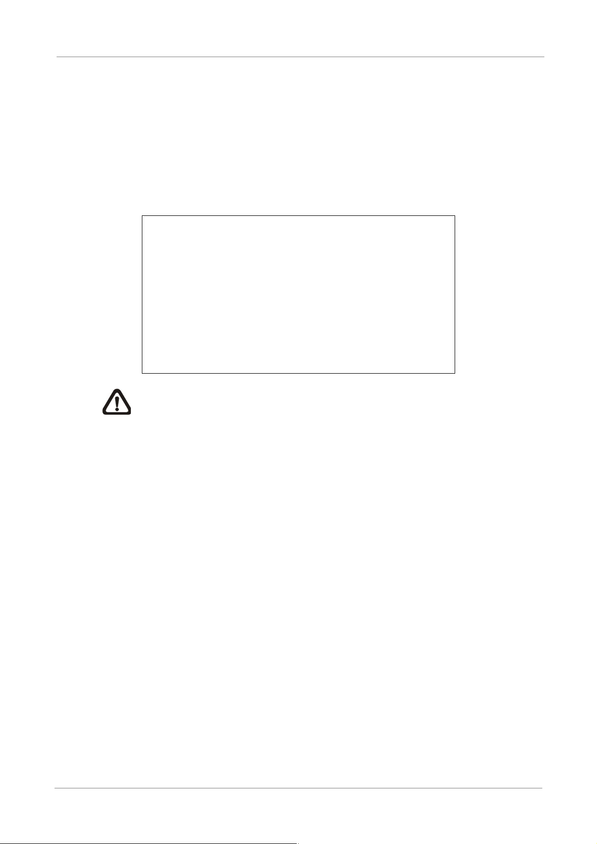
Key Usage in Virtual Keyboard
A virtual keyboard shows up while editing settings such as camera title, DVR name,
etc. The virtual keyboard displays as follows.
A B C D E F G H I J K L M
N O P QRSTUVWXYZ
a b c d e f g h i j k l m
n o p q r s t u v w x y z
0 1 2 3 4 5 6 7 8 9
# _ , “ + = *
Backspace Delete
Cancel OK
.
!@
7
Page 9

OSD Setup Manual
<To input characters>
Move the cursor by pressing Direction keys and press ENTER to select characters.
Alternatively, press channel keys 1~9 to directly enter number 1~9, press channel
key 10 to directly enter number 0, or press “CALL” key to directly enter a period
mark “.”. The hot keys are for speeding up inputs of IP addresses or etc.
<To move the cursor in entry field>
Select <> / <> and press ENTER to move the cursor to left / right in the entry
field.
<To delete previous character>
Select <Backspace> and press ENTER, or press DOME.
<To delete current character>
Select <Delete> and press ENTER..
<To exit the virtual keyboard>
Select <OK> and press ENTER to save the settings and exit, otherwise press ESC
or select <Cancel> and press ENTER to exit without saving changes.
8
Page 10

OSD Setup Manual
ʳ ʳ ʳ ʳ ʳ ʳ
System Setup
Select <System Setup> from the Main Menu and press ENTER to enter the System Setup
menu. The items in the System Setup menu are described in the following sections.
System/Version Info
Language
Date/Time
DVR Name
User Management
Network Setup
RS485 Setup
Audio Output/Key Beep
IP Camera Support
System Setup
English
DVR
0
< System/Version Info >
The System/Version Info menu allows users to view system information such as hardware
and software version. From the System Setup menu, select <System/Version Info> and
press ENTER. The following menu is displayed. The first five items are “read only”, thus
CANNOT be changed. The items in this menu are described in the following subsections.
System/Version Info
Model Name
Video System
Hardware
Software
MAC Address 1
Software Upgrade Via Local Device
Software Upgrade Via Internet
****-****-****-****
**:**:**:**:**:**
****
NTSC
**-**-**
Model Name
This item shows the model name of the DVR.
Video System
This item shows the current video system of the DVR.
Hardware
This item shows the hardware version of the DVR.
Software
This item shows the software version installed on the DVR.
9
Page 11
OSD Setup Manual
MAC Address 1
This item identifies the first Media Access Control (MAC) address of the DVR.
Software Upgrade Via Local Device
This item is used for updating software of the Versatile H.264 DVR via local device.
The menu is displayed as follows.
Software Upgrade via Local Device
Upgrade Version
xxxx-xxxx-xxxx-xxxx
Connect an USB storage device containing upgrade software to the DVR; the
available upgrade files will be listed in the menu. To update the system, select a file
and use UP / DOWN keys to choose <Yes>. Press ENTER to confirm the selection
and start the upgrade process. The Versatile H.264 DVR will download the
software, update the system files, and reboot automatically.
Select
No
The upgrade may take several minutes to save the changes in the memory of the
system. After the DVR is rebooted, please check the software version again.
NOTE: Power interruption is NOT allowed during the software update.
Ensure that no power interruption can occur until the DVR is completely
rebooted.
NOTE: Do not remove the external USB ThumbDrive / DVD+RW before the
DVR has completely shutdown (hard drive and fan are off). Removing the
external USB ThumbDrive / DVD+RW before shutdown can cause the
system to update improperly.
Software Upgrade Via Internet
The item is used to upgrade the unit’s software via the internet. Select one of the
listed software versions and choose <Yes>. The Versatile H.264 DVR will
download the software, update the system files, and reboot automatically.
10
NOTE: This menu item is only available in 8CH and 16CH models.
Page 12
OSD Setup Manual
< Language >
The Language item allows users to select the language for the OSD menu and screen
messages. Language selection takes effect immediately when the selection is made. Press
UP / DOWN to select from listed languages and press ENTER to confirm.
< Date/Time >
Users can set the current date, time and other OSD parameters in this menu. Login using
account with proper privilege to enter the submenu. In System Setup menu, select
<Date/Time> and press ENTER. The Date/Time menu displays as follows.
Date/Time
Date
Time
Time Zone
Date/Time Display
Date Display Mode
Time Display Mode
Date/Time Order
Daylight Saving Time Setup
Network Time Protocol Setup
2008/02/21
PM10:39:26
OFF
1 Row
Y/M/D
12 HR
Date First
NOTE: The reset of date / time setting only applies to new video. The date and time
of previously recorded video will not be changed.
NOTE: To avoid database corruption, formatting the database is recommended after
changing Date/Time setting.
Date / Time
Select <Date> or <Time> and press ENTER to adjust the settings. LEFT / RIGHT
keys are used to move the cursor to previous or next field, ENTER is for selecting,
and UP / DOWN are used to change the value in the selected field.
11
Page 13
OSD Setup Manual
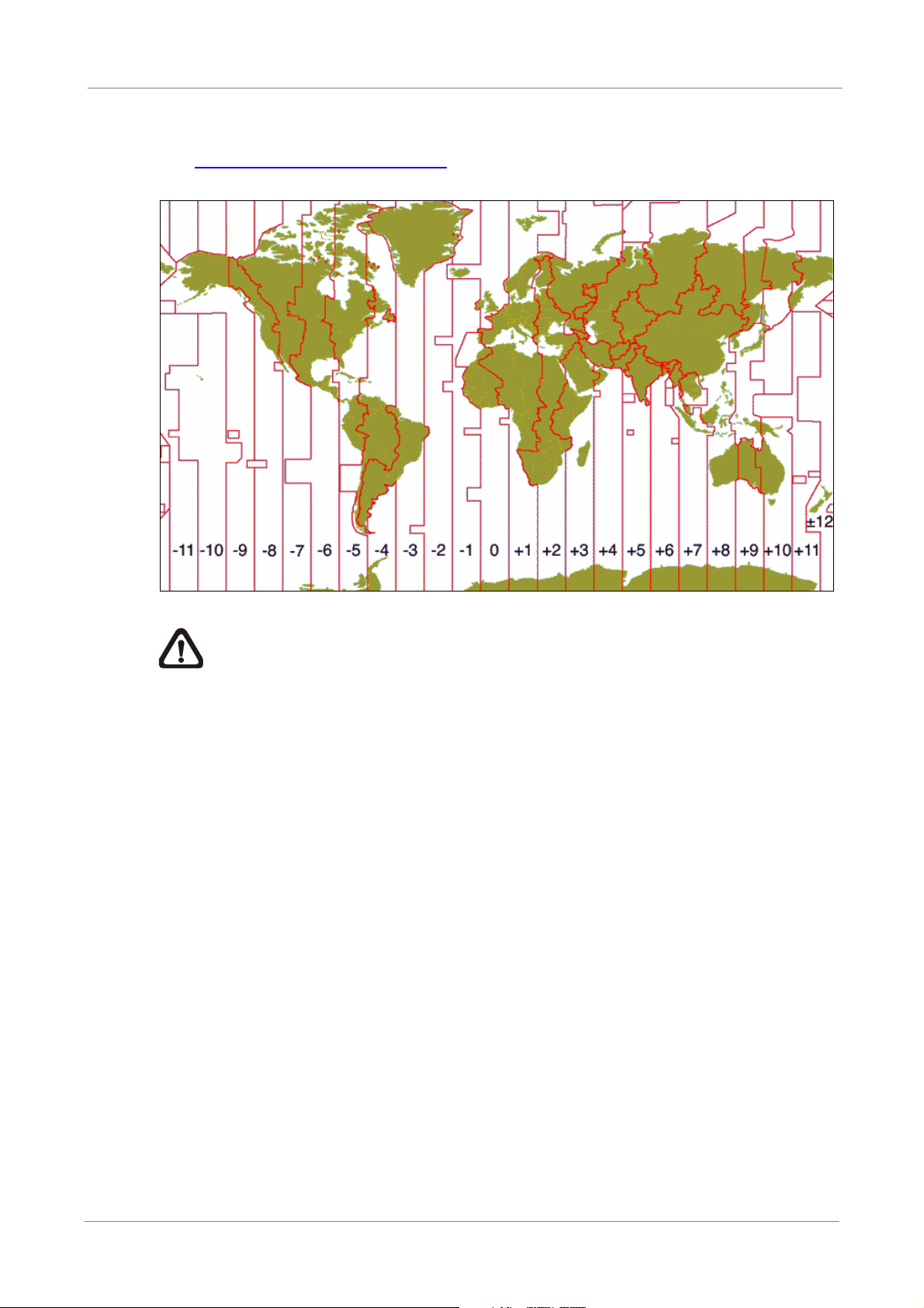
Time Zone
Press ENTER to set users’ local time zone. Please refer to the following figure or
visit www.greenwichmeantime.com
to find out users’ local time zone.
NOTE: <Time Zone> must be set to users’ local time zone or the <Network
Time Protocol Setup> will not be accessible.
Date/Time Display
The date/time display can be set to be shown in 1 row, 2 rows, or not shown. Use
the UP / DOWN keys to change the setting.
Date Display Mode
This menu allows users to set the display type of the date. Three options are
provided: <Y/M/D>, <M/D/Y> or <D/M/Y>. “Y” represents “Year”, “M” represents
“Month” and “D” represents “Day”. Use UP / DOWN keys to change the setting.
Time Display Mode
Users can set the time format to <12 hour> or <24 hour>. Use the UP / DOWN
keys to change the format.
12
Page 14

OSD Setup Manual
Date/Time Order
This item is used to set the order of Date/Time display to <Date First> or <Time
First>. Select this item and press UP / DOWN keys to change the setting.
Daylight Saving Time Setup
This function is for people who live in certain regions to observe Daylight Saving
Time. The menu displays as follows:
Daylight Saving Time Setup
Daylight Saving Time
DST Start
DST End
DST Bias
- Daylight Saving Time
Select <ON> to enable, or <OFF> to disable the function. If the function
is disabled, the DST Start / End time and DST Bias will be grayed out and
st
Apr. 1
Oct. Last Sun, 02:00
Sun, 02:00
OFF
60 Min
cannot be accessed. If this function is enabled, the date/time information
will be shown on the screen with a DST icon when playing back recorded
video or searching video in the event list. “S” indicates summer time and
“W” indicates winter time.
- DST Start / End
These items are used to set duration of daylight saving time. Use LEFT /
RIGHT to move the cursor to the previous or next field, UP / DOWN to
change the settings.
- DST Bias
This item allows users to set the amount of time to move forward from the
standard time for daylight saving time. Available options are <30>, <60>,
<90> and <120> minutes.
Network Time Protocol Setup
After time zone is set, the <Network Time Protocol Setup> option will be available.
Network Time Protocol Setup
NTP Server
Automatically Time Sync
Manually Time Sync
time.nist.gov
ON
No
13
Page 15

OSD Setup Manual
- NTP Server
- Automatically Time Sync
- Manually Time Sync
Enter this item to setup a feasible time server. The default time server is
time.nist.gov. Users can change it to any other time server if desired. IP
addresses of other time servers are listed below for reference.
129.6.15.28 129.6.15.29 132.163.4.101
132.163.4.102 132.163.4.103 128.138.140.44
192.43.244.18 131.107.1.10 69.25.96.13
206.246.118.250 208.184.49.9 64.125.78.85
207.200.81.113 64.236.96.53 68.216.79.113
Select <ON> and the time will be synced once an hour.
Select <Yes> to sync the time immediately.
< Unit Name >
Users are allowed to assign a unit name, up to 11 characters, to the Versatile H.264 DVR.
Follow the steps below to edit the unit name.
x Select <Unit Name> from System Setup menu and press ENTER. A virtual
keyboard displays as below.
Unit Name
A B C D E F G H I J K L M
N O P QRSTUVWXYZ
a b c d E f g h i j k l m
n o p q R s t u v w x y z
0 1 2 3 4 5 6 7 8 9
# _ , “ + = *
Backspace Delete
Cancel OK
.
!@
14
x Use Direction keys to move the cursor to the wanted character.
x Press ENTER to add the character to the entry field (up to 11 characters).
x When the unit name is entered, move the cursor to <OK> and press ENTER to
save the settings and exit.
Page 16
OSD Setup Manual
< User Management >
The DVR provides the option to create up to seven sets of usernames and passwords with
customized authority, excluding the preset “admin” account. The menu is as the following.
User Management
Password Protection
Account Setup
Authority Setup
Load Default Setting
Password Protection
Select <ON> to request for username and password for accessing functions listed
in Authority Setup menu, or select <OFF> to allow free access.
Account Setup
Setup customized username, password, and authority level in this menu. Press
Direction keys and ENTER to select items. The username(ID) is case sensitive.
ON
No
The authority level ranks from level 1~8, and level 8 has highest authority.
Alternatively, select <Disable> to stop using the account.
Account Setup
Account
admin
user
user2
user3
user4
user5
user6
user7
NOTE: The username and authority level of the preset “admin” account
cannot be changed.
ID
Edit
Edit
Edit
Edit
Edit
Edit
Edit
Edit
PWD
Edit
Edit
Edit
Edit
Edit
Edit
Edit
Edit
Authority
Level 8
Level 4
Level 4
Level 4
Level 4
Level 4
Level 4
Level 4
15
Page 17
OSD Setup Manual
Authority Setup
Setup permitted authority level for accessing the functions listed in this menu. The
functions include: Playback/Search, Dome Control, Call Control, Export Data,
Menu Access, System Setup, Monitor Setup, Camera Setup, Record Setup,
Sequence Setup, Event Setup, Database Setup, Configuration and Shutdown.
Press Direction keys and ENTER to select from items. The authority level ranks
from level 1~8, and level 8 has highest authority. Alternatively, select <Disable> to
allow free access.
FIRST PAGE
Item
Playback/Search
Dome Control
Call Control
Export Data
Menu Access
System Setup
Monitor Setup
Camera Setup
Record Setup
Authority Setup
Authority
Level 4
Level 4
Level 4
Level 4
Level 4
Level 4
Level 4
Level 4
Level 4
NOTE: The “Menu Access” cannot be set to <Disable>.
When the account does not have authority to access certain functions, an error
message will be displayed on the screen.
Load Default Setting
This item is for restoring the default settings. Select <Yes> to load default setting or
select <No> to exit.
16
Page 18

OSD Setup Manual
< Network Setup >
The Network Setup menu allows users with proper privilege to configure the network by
specifying the network related settings, such as IP address and Netmask, etc. Check with
the network administrator and/or network service provider for more specific information.
The menu is as the following. Items in this menu are described in the following sections.
Network Setup
LAN Select
LAN Setup
Trigger Port
Email Address
SMTP Setup
DDNS Setup
LAN Select
This item allows users to select the network type among <LAN>, <PPPoE>, and
<None>. If the internet connection is a local area network communication, please
LAN
80
select <LAN>. If the internet connection is a broadband medium, such as DSL Line
or cable modem, please select <PPPoE>.
PPPoE stands for Point-to-Point Protocol over Ethernet. It is a specification for
connecting the users on an Ethernet to the Internet through a common broadband
medium.
If <None> is selected, then there is no need to set further LAN or PPPoE settings.
Therefore, the second item <LAN Setup>will be inaccessible.
LAN Setup
The network related settings in the LAN Setup menu should be associated with the
network service type. Select <LAN Setup> in Network Setup menu and press
ENTER to set the parameters. The menu displays as follows.
LAN Setup
DHCP
IP
Netmask
Gateway
DNS
PPPoE Account
PPPoE Password
PPPoE Max Idle
Connect At Booting
Network Restart
192.168.1.150
255.255.255.0
192.168.1.1
OFF
0.0.0.0
35min
Yes
No
17
Page 19

OSD Setup Manual
- DHCP
- IP
This item allows users to obtain a dynamic IP address from DHCP
(Dynamic Host Configuration Protocol) server when the DVR boots up.
When using DHCP, the settings are dynamic and will change every time
the DVR power on or off, depending on the network's setup.
If the item is enabled (ON), a dynamic IP will be assigned to Versatile
H.264 DVR. In this case, users do not need to set a static IP and the
Ethernet settings, including IP address, Netmask, Gateway, and DNS
settings will be read-only.
If the DVR is using a permanent address, disable DHCP (OFF) to
manually set IP Address, Netmask, Gateway, and DNS. See the network
system administrators or IT personnel for appropriate values.
This item is used to configure the IP (Internet Protocol) address of the
DVR. The IP address is the identifier for the DVR on a TCP/IP LAN.
Please note that to set a static IP address, DHCP must be set to <OFF>.
- Netmask
A netmask is a 32-bit mask used to divide an IP address into subnets and
specify the networks available hosts. Its value is defined by the network
administrator. It takes the form as ***.***.***.***, for example,
255.255.255.255.
This item allows users to enter the value of the Netmask for the DVR.
Please note that to configure this item, DHCP must be set to <OFF>.
- Gateway
Gateway is a node on a network that serves as an entrance to another
network. Users are allowed to specify the IP address of the gateway or
router associated with this DVR. To configure this item, DHCP must be
18
set to <OFF>.
Page 20
OSD Setup Manual
- DNS
DNS is the abbreviation for “Domain Name Server”, which is an Internet
service that translates domain names into IP addresses. The advantage
of using DNS is that domain names are easier to remember.
This item allows users to specify the IP address of the Domain Name
System associated with the DVR. To configure this item, DHCP must be
set to <OFF>.
If the server is unavailable when using DHCP, the DVR will search for the
network server and boots up more slowly. This network search continues
until it times out.
- PPPoE Account
The item allows users to setup the PPPoE login username.
NOTE: For accessing the PPPoE settings, select <PPPoE> as
the Network Type in Network Setup menu.
To setup the login username, follow the steps:
x Select <PPPoE Account> from LAN Setup menu and press ENTER.
A virtual keyboard displays.
PPPoE Account
ABCDEFGHI JKL M
NOPQRSTUVWX Y Z
abcde f gh i j k l M
nopqr s t uvwxy Z
0123456789.! @
#_ ,” +=*
Backspace Delete
Cancel OK
x Use Direction keys to move the cursor to the desired character.
x Press ENTER to add the character to the entry field.
x When it’s done, move the cursor to <OK> and press ENTER to save
the setting and exit.
19
Page 21

OSD Setup Manual
- PPPoE Password
- PPPoE Max Idle
- Connect At Booting
The item allows users to setup the PPPoE password. Follow these steps
to setup the login password.
x Select <PPPoE Password> from LAN Setup menu and press ENTER.
A virtual keyboard displays.
x Use Direction keys to select from characters.
x Press ENTER to add the selected character to the entry field.
x When it’s done, move the cursor to <OK> and press ENTER to save
the setting and exit.
The item indicates the duration that the modem connection remains
active if there is no acknowledgement from the remote PC. Users can
select the idle time from 0 to 600 minutes.
The DVR is allowed to automatically connect to the internet when booting
up. Select <Yes> to connect at booting, otherwise select <No>.
- Network Restart
Network restart is required after network settings are changed. Select
<Yes> to restart the network connection.
Trigger Port
To avoid the default service port (port 80) being jammed, this item enables users to
change port 80 to another port.
To change the trigger port, move the cursor over <Trigger Port> and press ENTER,
then adjust the setting by UP / DOWN keys.
Email Address
This item is used to edit the e-mail address where alarm event information will be
sent. Follow these steps to setup the e-mail address.
20
x Select <Email Address> from Network Setup menu and press ENTER. A
virtual keyboard displays.
x Use Direction keys to move the cursor for selecting from characters.
x Press ENTER to add the selected character to the entry field.
x When it’s done, move the cursor to <OK> and press ENTER to save the
settings and exit.
Page 22

OSD Setup Manual
SMTP Setup
Simple Mail Transfer Protocol (SMTP), a protocol for sending e-mail messages
between servers. SMTP is a relatively simple, text-based protocol that one or more
recipients of a message are specified and the message text is transferred.
Select < SMTP Setup> from Network Setup menu and press ENTER; the menu
displays as follows.
SMTP Setup
Email Via SMTP
SMTP Server
SMTP Port
SMTP Account
SMTP Password
- Email Via SMTP
The item enables users to determine if the DVR sends e-mail via SMTP.
ON
25
Select <ON> to send e-mail via SMTP using direction keys; if not, select
<OFF>.
- SMTP Server
This item enables users to set the SMTP server. Contact the network
service provider for more specific information.
Follow the steps to setup the SMTP Server.
x Select <SMTP Server> from SMTP Setup menu and press ENTER. A
virtual keyboard displays.
SMTP Server
ABCDEFGHI JKL M
NOPQRSTUVWX Y Z
abcde f gh i j k l m
nopqr s t uvwxy z
0123456789.! @
#_ ,” +=*
Backspace Delete
x Use Direction keys to move the cursor to the desired character.
Cancel OK
x Press ENTER to add the selected character to the entry field.
x When it’s done, move the cursor to <OK> and press ENTER to save
the settings and exit.
21
Page 23

OSD Setup Manual
- SMTP Port
- SMTP Account
The item is used to change SMTP port to another port, if necessary.
SMTP usually is implemented to operate over Internet port 25.
To change the SMTP port, move the cursor to <SMTP Port> in SMTP
Setup menu and press ENTER. Use UP / DOWN keys to change the
values.
The item allows users to setup the SMTP username. Follow these steps
to setup the login username.
x Select <SMTP Account> from SMTP Setup menu and press ENTER.
A virtual keyboard displays.
x Use Direction keys to move the cursor for selecting from characters.
x Press ENTER to add the selected character to the entry field.
x When it’s done, move the cursor to <OK> and press ENTER to save
the settings and exit.
- SMTP Password
The item allows users to setup the SMTP password. Follow these steps
to setup the password.
x Select <SMTP password> from SMTP Setup menu and press
ENTER. A virtual keyboard displays.
x Use Direction keys to move the cursor for selecting from characters.
x Press ENTER to add the selected character to the entry field.
x When it’s done, move the cursor to <OK> and press ENTER to save
the settings and exit.
DDNS Setup
Dynamic Domain Name System (DDNS) allows a DNS name to be constantly
synchronized with a dynamic IP address. In other words, it allows those using a
dynamic IP address to be associated to a static domain name so others can
connect to it by the domain name.
22
Once the setting is completed, the DDNS address will be:
http://hostname.ddns.iview-ddns.com
Fore example, if the chosen host name is “H264DVR”, then the address will be:
http://H264DVR.ddns.iview-ddns.com
Page 24

OSD Setup Manual
Select <DDNS Setup> from Network Setup and press ENTER. The menu displays
as below.
DDNS Setup
Enable DDNS
Host Name
DDNS Port
Submit/Update
ezDDNS
XXXX_XXXXXX
ON
80
No
No
- Enable DDNS
The item is used to enable or disable the Dynamic Domain Name Service.
Select <ON> to enable the service, or <OFF> to disable.
- Host Name
The item allows users to setup a domain name, which is used for
entering the Versatile H.264 DVR through internet on the remote PC.
To setup the host name of the DVR, follow the steps.
x Select <Host Name> from DDNS Setup menu and press ENTER. A
virtual keyboard displays as below.
Host Name
ABCDEFGHI JKL M
NOPQRSTUVWX Y Z
abcde f gh i j k l m
nopqr s t uvwxy z
0123456789.! @
#_ , “+=*
Backspace Delete
Cancel OK
x Use Direction keys to select character.
x Press ENTER to add the selected character to the entry field.
x When it’s done, move the cursor to <OK> and press ENTER to save
the settings and exit.
NOTE: Each Versatile H.264 DVR should have a unique
host name.
- DDNS Port
The item allows users to setup the port for DDNS. Press UP / DOWN
Direction keys to change the port.
23
Page 25

OSD Setup Manual
- Submit/Update
When the settings are finished, move the cursor to this item and select
<Yes> to submit the settings.
NOTE: If more than one Versatile H.264 DVR has the same
domain name, only the first one will be submitted successfully.
- ezDDNS
ezDDNS enables the users to register for host name automatically.
Press ENTER and select <Yes>. The following screen will be displayed:
ezDDNS Submit/update ok!
Host name is XXXX_XXXXXX
Press any key to return
NOTE: The DVR must be connected to the *Real IP address, or
be assigned a specific port using **Port Forwarding technique.
*A "Real IP" is an IP address that is assigned to users by the ISP.
**A "Virtual IP" is an IP address assigned either manually or
through DHCP. When users are assigned a Virtual IP, users must
use Port Forwarding technique to assign a specific port to DVR.
< RS485 Setup >
This menu allows users to setup the parameters of the DVR’s RS-485 communication port.
From System Setup, select <RS485 Setup> and press ENTER. The following menu is
displayed.
RS485 Setup
Unit ID
Baud Rate
Bits
Stop
Parity
Unit ID
This item is used to change the RS-485 ID address of the DVR. The ID is in the
range of <1> to <255>.
Baud Rate
The Baud rate options for associated with the protocol are <2400>, <4800>,
224
9600
8
1
None
24
<9600>, <19200>, <38400> and <57600>.
Page 26

Bits
Users can specify the bits in a word associated with this protocol. The available
options are <6>, <7> and <8> bits.
Stop
Users can specify the stop bit associated with this protocol. Options are <1> and
<2> stop bits.
Parity
This item is used to specify the parity associated with this protocol. Options are
<ODD>, <EVEN> and <None>.
< Audio Output/Key Beep >
Enter this menu to setup the audio output or key beep.
OSD Setup Manual
Audio Output
This item is for setting the audio output mode. The audio will be outputted when the
monitor shows a chosen channel in full screen. The available options are as below.
<Live/PB>: Select this option to play the recording sounds of live image in live
mode, and sounds of recorded video in playback mode respectively.
<Always Live>: Select this option to play live sounds in both live mode and
playback mode.
<OFF>: Select this option to disable the audio output function.
Audio Output
Key Beep
Split Mode Audio
Audio Output/Key Beep
OFF
ON
OFF
Key Beep
This item is used to enable or disable the key tone. Select <ON> to enable the key
tone, or <OFF> to disable.
Split Mode Audio
This item allows users to select and output the audio of the selected channel while
viewing multiple channels. Select <CH1> through <CH16> to output the preferred
audio, or select <OFF> to disable audio output in multiple window viewing modes.
25
Page 27

OSD Setup Manual
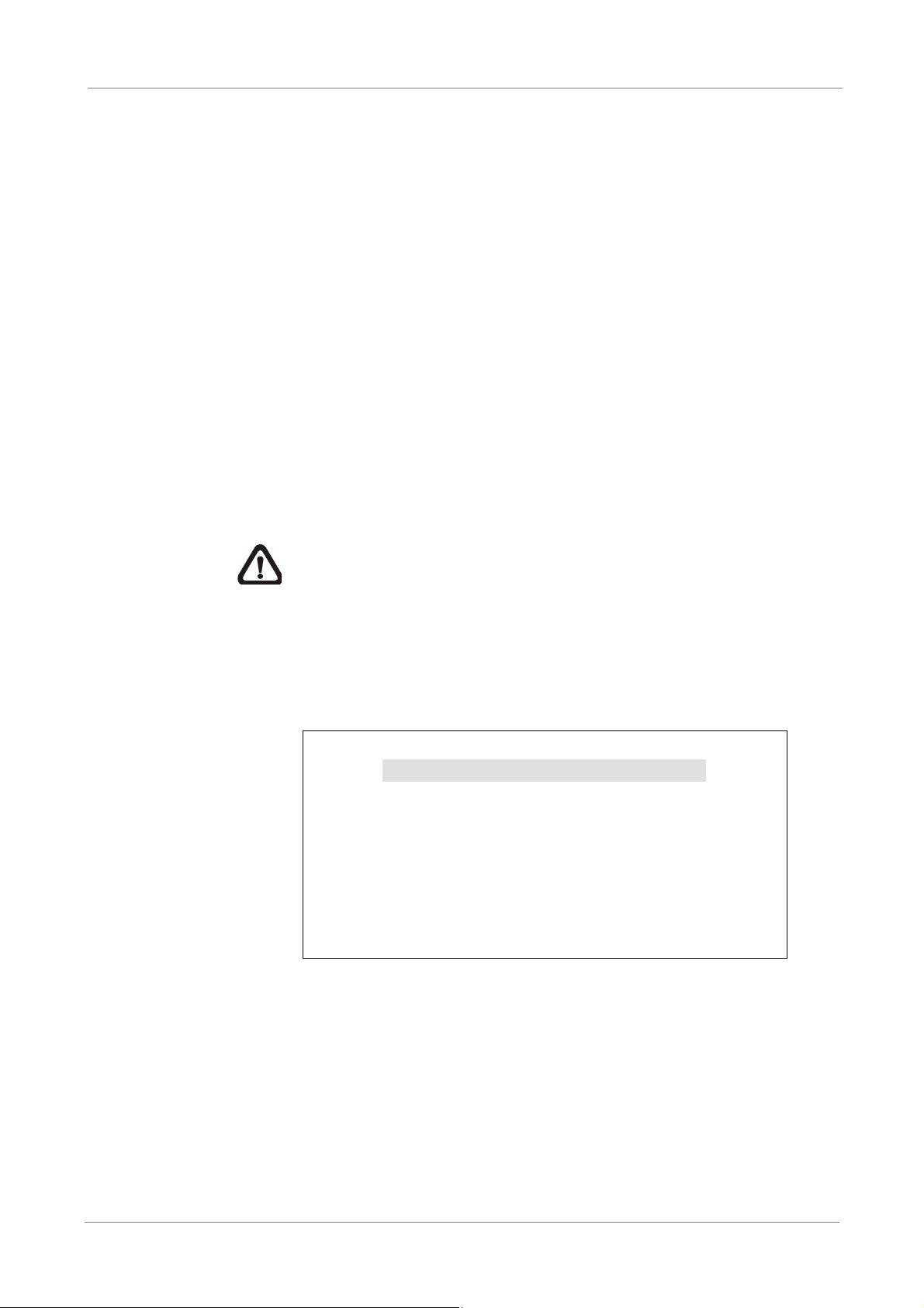
<IP Camera Support>
Enter this item to add IP cameras to the DVR. Setting this item to <0> will make DVR act as
a traditional analog DVR. Select any other number to allow the corresponding connection of
IP cameras to the DVR.
After a number is selected, the following message will be displayed. Press ENTER to apply
the changes, or ESC to exit.
Notice!!
DVR must be reboot to apply the change
ENTER: Yes ESC: No
NOTE:
1. The existing database will NOT be re-formatted after switching on this function.
2. Alarm I/O, Motion detection function, and audio of the IP camera are currently
NOT supported.
26
Page 28

OSD Setup Manual
ʳ ʳ ʳ
Monitor Setup
The Monitor Setup menu allows users to adjust the quality of the displayed image. Select
<Monitor Setup> from the Main menu and press ENTER. The following menu is displayed.
Show Camera Title
Screen Center Adjust
VGA Resolution
Show Color Bar
Monitor Setup
Yes
800×600
Execute
< Show Camera Title >
This item allows users to choose whether to display the camera title on the screen or not.
The default is <Yes>, which displays the camera titles with the video.
< Screen Center Adjust >
This item is used to adjust the screen center of the main monitor display area.
Follow the steps to set the center point.
x Select <Screen Center Adjust> from the Monitor Setup menu and press
ENTER. The adjusting screen is as follows.
Screen Center Adjust
+
x Position the screen center position using the Direction keys.
x Press ENTER to exit when finished.
< VGA Resolution >
This item allows users to select appropriate VGA resolution for the VGA monitor connected
to the DVR. The options are <800×600> (default), <1024×768> and <1280×1024>.
NOTE: If the selected VGA resolution is too high that the monitor cannot support, the
message “No Signal’’ will be shown on screen. Then please press ESC on the front
panel to restore the original setting.
< Show Color Bar >
Choose this item to display color bar pattern on the screen. The color bar helps to adjust
the monitor hue, saturation, text color, and display options. Press ESC to exit the color bar
pattern display and return to the OSD menu.
27
Page 29

OSD Setup Manual
ʳ ʳ ʳ ʳ ʳ ʳ ʳ
ʳ ʳ ʳ
Camera Setup
The items in the Camera Setup menu enable users to set camera parameters, including
camera title, dome protocol and ID for each connected camera. There will be separate
menus for analog cameras and IP cameras. Please refer to <Analog Camera> section if the
connected camera is an analog camera, or refer to <IP Camera> section when the
connected camera is an IP camera.
< Analog Camera >
If the connected camera is an analog camera, please continue with this section. Items in
this menu are described in the following subsections.
Analog Camera
Analog Camera Select
Dome Protocol
Dome ID
Camera Title
Covert
Brightness
Contrast
Saturation
Hue
CH1
None
0
CH1
No
0
0
0
0
Analog Camera Select
This item is used to select a camera for setting the parameters. The related
settings will follow the selected camera, such as dome protocol and camera title.
Move the cursor to <Analog Camera Select> and press ENTER, then select a
channel using UP / DOWN keys.
Dome Protocol
If the connected camera is a dome camera, select the communication protocol
associated with the dome camera using ENTER and Direction keys. The default is
set to <None>.
Dome ID
This item is used to assign an ID number to the selected dome camera. Note that
ID number must match the ID address set by the dome camera.
Camera Title
This item allows the users to change the title of each connected camera. By default,
28
the titles of cameras are numbered from 1 through 16 respectively. The title will be
displayed on the screen after the changes of the titles are set.
Page 30

OSD Setup Manual
Follow these steps to enter a new title for a camera.
x Move the cursor to <Camera Title> and press ENTER. A virtual keyboard with
alphanumeric characters is displayed as below.
Camera Title
A B C D E F G H I J K L M
N O P QRSTUVWXYZ
a b c d e f g h i j k l m
n o p q r s t u v w x y z
0 1 2 3 4 5 6 7 8 9
# _ , “ + = *
Backspace Delete
x Use Direction keys to select character.
x Press ENTER to add the selected character to the entry field.
x When it’s done, move the cursor to <OK> and press ENTER to save the
Cancel OK
.
!@
settings and exit.
Covert
This function allows users to set the specific camera to be covert while the DVR
continues to record video. Choosing <Yes> means to cover the selected camera;
and <No> to remain the specific camera non-covert.
Brightness
Select this item to adjust the brightness of the camera. Use UP / DOWN keys to
adjust the numeric value. The range of brightness values is from <-128> to <127>.
Contrast
Select this item to adjust the contrast of the camera. Use UP / DOWN keys to
adjust the value. The range of contrast values is from <-128> to <127>.
Saturation
Select this item to adjust the color saturation of the camera using UP / DOWN keys.
This value will be ignored on monochrome monitors. The range of saturation
values is <-128> to <127>.
Hue
Select this item to adjust the hue of the camera. Use UP / DOWN keys to adjust
the value. The range of hue values is from <-128> to <127>
29
Page 31

OSD Setup Manual
<IP Camera>
If the connected camera is an IP camera, please continue with this section. After the <IP
Camera Support> in System Setup menu is set to any number greater than 0 and the DVR
is rebooted, users will be able to setup the IP camera. Items in this menu are described in
the following subsections.
IP Camera
IP Camera Select
IP Camera Title
Hostname/IP
Model
Connection Setup
Device Setup
Activated
Status
IP Camera Select
Select the corresponding channels. If <IP Camera Support> is set to <1>, then last
channel will be the corresponding channel for IP camera. When <IP Camera
CH16
CH16
X.X.X.X
No
Support> is set to <2>, the last two channels can be used to setup the IP cameras,
and so on.
IP Camera Title
This item allows the users to change the title of each connected camera. By default,
the titles of cameras are numbered from 1 through 16 respectively. The title will be
displayed on the screen after the changes of the titles are set.
Follow these steps to enter a new title for a camera.
x Move the cursor to <Camera Title> and press ENTER. A virtual keyboard with
alphanumeric characters is displayed as below.
IP Camera Title
A B C D E F G H I J K L M
N O P QRSTUVWXYZ
a b c d e f g h i j k l m
n o p q r s t u v w x y z
0 1 2 3 4 5 6 7 8 9
# _ , “ + = *
Backspace Delete
Cancel OK
.
!@
30
x Use Direction keys to select character.
x Press ENTER to add the selected character to the entry field.
x When it’s done, move the cursor to <OK> and press ENTER to save the
settings and exit.
Page 32

Hostname/IP
This item allows users to enter the hostname or IP address of the IP camera (e.g.
192.168.1.123).
Model
Enter this item to select matching model of the IP camera. The DVR supports the
following IP camera models: <NH Series>, <D7521>, <ViVoTek 7000>, <AXIS
200>, <SONY SNC> and <ACTi Series>.
Connection Setup
This item allows users to setup the connection of the IP camera. Enter this item
and the following menu will be displayed.
Account
Password
Management Port
Streaming Format
Advance Streaming Options
Streaming Port
Streaming Protocol
IP Dome Protocol
OSD Setup Manual
Connection Setup
****
****
80
MPEG4
OFF
8090
RTP+RTSP
None
- Account
Enter the login account name of the IP camera.
- Password
Enter the login password of the IP camera.
- Management Port
The management port is the default port of the IP camera. Different IP
cameras may have different management ports.
- Streaming Format
Enter this item to select the streaming format of the IP camera. The DVR
supports three types of streaming format: <MPEG4>, <H264> and
<MJPEG>.
- Advance Streaming Options
Select <OFF> and the Streaming Port and Streaming Protocol will be set
automatically according to the camera model selected. Alternatively,
select <ON> to manually set the Streaming Port and Streaming Protocol.
31
Page 33

OSD Setup Manual
- Streaming Port
- Streaming Protocol
- IP Dome Protocol
Streaming port is used for transmitting video and related commands.
Enter this item to select the streaming protocol of the IP camera. The
DVR supports the following streaming protocols: <RTP+RTSP>,
<RTP/RTSP>, <RTP/RTSP/HTTP> and <HTTP>.
NOTE: Please contact the manufacturer of the IP camera for
assistance if the IP camera’s Management Port/ Streaming Port/
Streaming Format/ Streaming Protocol are unknown.
If the connected device is an IP Dome Camera, then select an
appropriate IP Dome Protocol from the provided options.
Device Setup
Enter this item to setup the basic settings of the IP camera. Upon entering this item,
the following message will be displayed.
Collecting data
Please wait!
If the connection cannot be detected, the following message will be displayed.
Please check the <Hostname/IP>, <Model> and <Connection Setup> again to
make sure the settings are correct.
Cannot get config from the IP device
When the connection is detected, the following menu will be displayed.
Device Setup
Product ID
Image Resolution
FPS
Compression
Quality
Sharpness
Brightness
Contrast
Saturation
Hue
Apply
****
CIF
15
40
Best
0
20
50
30
40
No
32
Page 34

OSD Setup Manual
NOTE: The contents of the Device Setup menu differ from camera model to
camera model. For instance, when IP Camera Brand A is connected, all
items may be available. However, when IP Camera Brand B is connected,
the menu may contain only 8 items. Refer to the following comparing table
for example.
<IP Camera Brand A> <IP Camera Brand B>
Product ID
Image Resolution
FPS
Compression
Quality
Sharpness
Brightness
Contrast
Saturation
Hue
Apply
Device Setup
****
CIF
15
40
Best
20
50
30
40
No
Product ID
Image Resolution
FPS
Quality
Sharpness
0
Contrast
Saturation
Apply
Device Setup
****
CIF
Best
- Product ID
15
0
20
50
No
This item will display the product name of the IP camera.
- Image Resolution/ FPS/ Compression/ Quality
These can be used to setup the Image Resolution/ FPS (Frames Per
Second)/ Compression/ Quality of the IP camera.
- Sharpness/ Brightness/ Contrast/ Saturation/ Hue
Move the cursor to the items and press ENTER to adjust the Sharpness/
Brightness/ Contrast/ Saturation/ Hue of the camera. Use UP / DOWN
keys to adjust the numeric value.
- Apply
Select <Yes> to apply the above settings, and the following message will
be displayed.
Re-collecting data
Please wait!
33
Page 35

OSD Setup Manual
Activated
Access this item and select <Yes> to activate the connection to the IP camera. To
deactivate the connection, select <No>
When the settings cannot be applied, the following message will be
displayed. Try to reduce the resolution or FPS of the IP camera. Note that
the login account of the IP camera should have administrator authority.
Cannot set the IP device
Otherwise, the <Device Setup> setting is completed.
NOTE: After changing any item under Device Setup menu, users
MUST set <Apply> to <Yes> to apply the changes, or the settings
will remain unchanged.
NOTE: Once the connection to the IP camera is activated, menu items
<Hostname/IP>, <Model>, <Connection Setup> will be grayed out and
cannot be accessed.
Status
After the connection to the IP camera is activated, users can check the connection
status. The menu will be shown as below.
Status
Model
Streaming Format
Resolution
PPS
Bandwidth
Pkg. lost rate
The information shown on the monitor is “ready only”.
20 KB/Sec
****
MJPEG
720*480
10
0.1%
34
Page 36

OSD Setup Manual
ʳ ʳ ʳ
Record Setup
The total record time of Versatile H.264 DVR will be effected by HDD capacity, recording
rate (Picture per Second), image quality settings and event settings.
The greater the recording rate and the higher the quality setting, the shorter the recording
duration. Most of the related factors can be set here in this submenu.
The Record Setup menu allows users to set recording quality, recording schedules, and
other recording parameters. Login using account with proper privilege to access Record
Setup menu. In the Main menu, move the cursor to <Record Setup> and press ENTER.
The following menu is displayed.
Record Setup
Record Mode Setup
Schedule Setup
Preset Config
Per Camera Config
ezRecord Setup
Data Lifetime
Circular Recording
Audio Recording
Purge Data
Best Quality
0 Days
ON
ON
< Record Mode Setup >
Enter this menu to setup record resolution. The relative record settings, such as preset
configuration, will follow the record mode setting. The menu is displayed as the following.
Record Mode Setup
Record Resolution
Record Format
Max Rec. PPS
CBR/VBR
Record Resolution
Select resolution of the recorded video. If the recording is set to NTSC system,
the selections are 720*480, 720*240, and 352*240. If the recording is set to
PAL system, the selections are 720*576, 720*288, and 352*288.
Record Format
Select format of the recorded video from <H264> and <MJPG>.
720*240
H264
60
CBR
35
Page 37

OSD Setup Manual
Max Rec. PPS
This item will be automatically changed according to record resolution.
CBR/VBR
This item allows users to select an encoding method for the unit.
CBR, standing for Constant Bit Rate, means a way to encode a file at a fixed
rate. That also indicates a CBR file has consistent file size and quality.
VBR, standing for Variable Bit Rate, allocates an appropriate amount of data
per second, depending on the complexity of the video file.
It's strongly suggested to use VBR encoding when reliable video quality is the
top priority.
NOTE: Since a VBR file doesn't have a fixed size, the HDD space
usage cannot be calculated and thus ezRecord function is not
supported for VBR mode. Therefore, if ezRecord is selected as the
preset record configuration, the option of this menu item will
automatically be set as <CBR>.
< Schedule Setup >
This submenu is used to set the day and night time, or weekend recording schedule. The
Day and Night schedules are for defining day time and night time; the Weekend schedule
can be modified for weekends and holidays.
Select <Schedule Setup> from the Record Setup menu and press ENTER; the following
menu is displayed.
Schedule Setup
Day Time Start
Day Time End
Night Time Start
Night Time End
Weekend Schedule
Weekend Start
Weekend End
AM 06:00
PM 18:00
AM 06:00
PM 18:00
ON
Fri 18:00
Mon
06:00
Day / NightʳTime Start / End
The Day/Night Start Time and End Time determines the duration of day/night
recording time. Time is indicated in 1-minute increments. The time display format in
this menu is based on the setting of <Time Display Mode> in <System Setup>.
36
Page 38

OSD Setup Manual
ʳ
Weekend Schedule
<Weekend Schedule> determines whether a weekend schedule is in effect.
Choose <ON> to take effect the related weekend settings.
Weekend Startʳ/ End
<Weekend Start> indicates the specific day and time when weekend schedule
should begin, for example, FRI 18:00. <Weekend End> indicates the specific day
and time when weekend schedule should end, for example, MON 06:00. Time is
indicated in 1-minute increments.
Note that the value users have set indicates when the regular Day and Night
scheduling ends, and Weekend recording begins.
< Preset Record Configuration >
<Preset Config> is used to select the preset recording quality and frame rate. Different
preset recording quality levels are offered for users to choose: <Best Quality>, <Standard>,
<Extended Record>, <Event Only>, <ezRecord >, <512Kbps DSL>, <256Kbps DSL>,
<128Kbps DSL> and <OFF>. According to various Record modes, the preset configuration
options for normal and event status are described in terms of relative recording rate PPS
(Picture Per Second) and recording size for each channel in the table below.
These preset conditions <Best Quality>, <Standard>, <Extended Record>, <Event Only>,
<ezRecord >, <512Kbps DSL>, <256Kbps DSL>, and <128Kbps DSL> override any other
quality and rate settings. Refer to the table below for file sizes of different preset conditions.
Note that <Event Only> and <ezRecord> are not included in the table because there are
further details for these two settings. <Event Only> will be described in <Event Setup>
section. <ezRecord> will be explained in <ezRecord Setup> section.
NTSC 720 X 480 @ 30PPS 720 X 240 @ 60PPS 360 X 240 @ 120PPS
PAL 720 X 576 @ 25PPS 720 X 288 @ 50PPS 360 X 288 @ 100PPS
Best
Standard
Extended
512Kbps DSL
256Kbps DSL
128Kbps DSL
NOTE: The total PPS is equally shared by all channels, which means, even if one
channel has not been connected with a camera, the channel still reserves its share
of PPS. However, if <ezRecord> is selected, the channels not connected to
22 KB/Pic 12 KB/Pic 6 KB/Pic
14 KB/Pic 8 KB/Pic 4 KB/Pic
6 KB/Pic 4 KB/Pic 2 KB/Pic
4 KB/Pic
3 KB/Pic
2 KB/Pic
cameras will not be recorded. In other words, the total PPS will be shared by
channels with cameras connected only.
37
Page 39

OSD Setup Manual
< Per Camera Config >
This sub-menu is used to set the Day / Night / Weekend PPS and recording quality for each
individual channel. <Preset Configuration> must be set to <OFF> in order to access these
related settings. The menu is displayed as below in Record mode: 720×240@60PPS in
NTSC / 720×288@50PPS in PAL.
Per Camera Config
Cameral Select
Normal PPS
Normal Qlty
Event Max PPS
Event Qlty
Event Act
Day
7.5
Mid
30
Best
Both
Night
7.5
Mid
30
Best
Both
Camera Select
The item is used to select a desired channel for setting the parameters. Move the
cursor to <Camera Select> and press ENTER, then select a channel using UP /
CH1
Weekend
7.5
Mid
30
Best
Both
DOWN keys. Press ENTER again to confirm the selection.
Normal PPS
Normal PPS is used to set the recording rate for normal status.
Please note that the total normal PPS of all channels cannot exceed the maximum
PPS of each Record mode. To increase one channel’s PPS, others’ may have to
be reduced first. Event PPS is not restricted to this rule, since a smart event
scheduler will handle to the total PPS with a correct weighting. For example, if
channel 1 is set to event mode with 30PPS, the remaining 30 PPS will be equally
distributed to other 15 channels, which means each channel will be set to 2 PPS.
Normal Qlty
This item is used to set the picture size for normal status recording. The available
options are: <Low>, <Fair>, <Mid>, <High> and <Best>.
Event Max PPS
<Event Max PPS> is used to set the event recording rate for Event status. Usually,
the Event PPS is set equal to or greater than the Normal PPS. The setting is
depending on users’ application. If the Event PPS is set to <0>, the DVR will not
record event video when alarms triggered.
38
Page 40

OSD Setup Manual
Event Qlty
This item is used to set the picture size for event status recording. The available
options are: <Low>, <Fair>, <Mid>, <High> and <Best>.
Event Active
Users are allowed to choose which alarm type needs to be recorded. The available
options are <Alarm> (alarm events only), <Motion> (motion detection events only)
and <Both> (alarm event + motion detection), and <None>. The default setting is
<Both>, which includes Alarm and Motion events recording.
< ezRecord Setup >
This item aims to ease the complicated record settings, and to make the setup much easier.
Note that this item can be accessed only when <ezRecord> is selected as the option for
<Preset Config>.
Select <ezRecord Setup> from <Record Setup> and press ENTER, the menu is displayed
as below:
Follow these steps to Setup ezRecord:
ezRecord Setup
How Many Days To Record
Daytime Record
Night Record
Weekend Record
Average Normal PPS
Average Normal Quality
Record Info
2 Days
Yes
Yes
Yes
3.75
Best
x Select <How Many Days To Record> and press ENTER, then press
UP/DOWN to select a desired number of days. The average normal PPS &
quality will be adjusted automatically. The maximum recording days depends
on the storage size of the HDD. In other words, the larger the storage size,
the more days the DVR can record.
x Move to <Daytime Record> and press ENTER. This item is for users to select
whether the DVR will record during daytime. If yes, use UP/DOWN to select
<Yes> to enable daytime recording; or select <No> to disable.
x Repeat the same procedures for <Night Record> and <Weekend Record>,
respectively. Note that <Weekend Record> will be inaccessible if <Weekend
Schedule> in <Schedule Setup> is set to <OFF>.
39
Page 41

OSD Setup Manual
x Select <Average Normal PPS> and press ENTER, then press UP/DOWN to
choose a desired number of PPS. The <How Many Days To Record> will be
computed automatically.
x Select <Average Normal Quality> and press ENTER, then press UP/DOWN
to select a desired quality. The <How Many Days To Record> will be
computed automatically.
NOTE: The current number of connected cameras will affect the
recording quality automatically calculated by the <ezRecord Setup>.
Therefore, when there are cameras disconnected or connected, the
<ezRecord Setup> should be reset.
< Data Lifetime >
Data Lifetime indicates the duration that a video is saved and recallable in the HDD. Only
those video recorded during Data Lifetime can be retrieved for playback. The video
exceeded Data Lifetime will be hidden and cannot be retrieved for playback. Press ENTER
to select this item in Record Setup menu, and then use UP / DOWN keys to set the data
lifetime. The value ranges from <1> to <365> days, or select <0> to disable the function.
NOTE: If users want to playback a video which is beyond the data lifetime, please
extend the duration till the recording data/time of the video is included.
< Circular Recording >
Users can choose to record video in circular mode or in linear mode. If circular mode (set to
<ON>) is selected, the DVR will store new video data to overwrite the oldest recorded video.
If linear mode (set to <OFF>) is selected instead, the DVR will stop recording when HDD
capacity is full. The percentage of HDD usage will be displayed at the lower-left corner of
the screen. Furthermore, a reminder message “ALMOST FULL” will show up at the
upper-right corner of the screen when HDD usage reached 98%. In the mean time, an
internal buzzer will start beeping.
From the Record Setup menu, move the cursor to <Circular Recording> and press ENTER,
then select <ON> / <OFF> using UP / DOWN keys.
< Audio Recording >
This item allows users to enable / disable Audio recording function of the DVR. When it’s
set to <ON>, audio input is recorded and saved with the video. When it’s set to <OFF>,
audio is ignored.
40
Page 42

OSD Setup Manual
< Purge Data >
This item is used to delete the Normal or Event videos. In <Record Setup> menu, move the
cursor to <Purge Data> and press ENTER. The <Purge Data> menu is shown as below.
Purge Data
Purge All Data
Purge All Event Data
Purge Event Before
Start To Purge
2008/01/01
Purge All Data
This item is used to delete all videos from the database. Use UP / DOWN keys to
select <Yes> and start the deletion by setting <Start to Purge> to <Yes>.
Purge All Event Data
This item is used to delete all event videos from the database. Use UP / DOWN
keys to select <Yes> and start the deletion by setting <Start to Purge> to <Yes>.
No
No
No
Purge Event Before
This item is used to delete event video before a specific date. Use LEFT / RIGHT
keys to move the cursor to next or previous field, ENTER to select the item and UP
/ DOWN to adjust the value. Start the deletion by setting <Start to Purge> to <Yes>.
Start To Purge
After selected the videos to be deleted or chosen the date for deletion, set this item
to <Yes> to start the deletion, or select <No> to cancel.
41
Page 43

OSD Setup Manual
ʳ ʳ ʳ ʳ
Sequence Setup
The Sequence Setup menu allows users to set the camera sequence schedule and dwell
time for main and call monitor. Select <Sequence Setup> in main menu and press ENTER.
The menu displays as follows.
Main Monitor Dwell
Main Monitor Schedule
Call Monitor Dwell
Call Monitor Schedule
Items in the <Sequence Setup> menu are described in the following subsections.
Sequence Setup
5 Sec
5 Sec
< Main / Call Monitor Dwell >
The main/ call monitor can be set to display full screen video of all installed cameras in
sequence. This item is used to set the Main/ Call Monitor dwell time, which is the duration of
time elapsed before switching to the next channel. The dwell time is in the range of 1 to 120
seconds.
< Main / Call Monitor Schedule >
This item is used to set displaying sequence of connected cameras to be displayed on the
main/ call monitor in full-screen format. Move the cursor to <Main Monitor Schedule> and
press ENTER. The menu is displayed as follows.
Main Monitor Schedule
________
________
Press Channel Keys To Select Channel
Press Key To Delete
Follow these steps to set a sequence:
x Press LEFT direction key to delete the original setting.
x Press the desired Channel keys to assign the camera to the position where
the cursor stops.
x Continue the steps until the sequence is completed.
The maximum number of entries in a sequence equals to the number of channels. Users
can select fewer than the maximum entries for camera sequence and leave the remaining
entries blank. The sequence can include a specific camera or cameras multiple times.
42
Page 44

OSD Setup Manual
ʳ ʳ ʳ
Event Setup
This menu allows users to determine Versatile H.264 DVR behavior in response to alarm
events. In the Main menu, move the cursor to <Event Setup> and press ENTER. The
following menu is displayed. Items in the Event Setup menu are described in the following
subsections.
Event Setup
Internal Buzzer
Event Icon
Email Notice
Email Attachment
Event Full Screen
Event Duration
Per Channel Config
ON
ON
OFF
OFF
None
20 Sec
< Internal Buzzer >
This item allows users to enable / disable internal buzzer of the Versatile H.264 DVR. If
<ON> is selected, the buzzer is activated in response to alarm events. If <OFF> is selected,
the buzzer is not activated.
< Event Icon >
This item enables (ON) / disables (OFF) the display of event icons on the monitor when
alarm events occur. The event icons are represented by a character according to the event
types respectively. Refer to the following table for association of event icons and event
types.
Event Icon Event Type
A
M
L
Alarm in event
Motion detection event
Video loss event
< Email Notice >
The item enables (ON) / disables (OFF) the Email notification of an event. When an alarm
event is triggered and <Email Notice> is enabled, an e-mail concerning the alarm event will
be sent.
NOTE: In order to send an event notification e-mail successfully, ensure that the
DVR is connecting to the internet.
43
Page 45

OSD Setup Manual
< Email Attachment >
The function allows the DVR to send out a brief AVI video regarding the event. The number
of the attached AVI video will be equivalent to the number of cameras connected to the
DVR. For example, if the DVR has been connected with 8 cameras, then 8 videos will be
attached to the notice email. The total size of the video will be about 2 MB.
Select <ON> to enable this function; or <OFF> to disable it.
NOTE: The video clips of the Email Attachment will ONLY be in *.avi format. Please
download the Divx Player from www.divx.com
to play the *.avi files.
< Event Full Screen >
This function allows the DVR to display the alarm channel in full screen size when an alarm
is triggered.
Select <None> to disable this function; select <Main> to display the alarm channel on Main
Monitor when an alarm is triggered; select <Call> to display the alarm channel on Call
Monitor; and select <Both> to display the alarm channel on both Main Monitor and Call
Monitor.
< Event Duration >
This item determines the duration of the buzzer and Alarm Out relay function after an alarm
is triggered. The available event duration range is from 5 second to 999 seconds.
< Per Channel Config >
This menu is used to configure <Video Loss Detect>,ʳˏMotion Detect>, <Alarm In> and
<Alarm Out> settings for each channel. The menu is displayed as below.
Per Channel Config
Channel Select
Video Loss Detect
Motion Detect
Motion Detect Indicator
Detection Config
Alarm In
Alarm Out
CH1
OFF
OFF
ON
OFF
ON
Channel Select
The item is used to select a desired channel for setting the parameters. Move the
cursor to <Channel Select> and press ENTER, then select a channel using UP /
DOWN keys. Press ENTER again to confirm the selection.
44
Page 46

OSD Setup Manual
Video Loss Detect
This item allows users to enable or disable Video Loss as an alarm event. Select
<ON> to enable Video Loss alarm events, or <OFF> to disable.
Motion Detect
This item allows users to enable or disable motion detection function of Versatile
H.264 DVR. Select <ON> to enable Motion Detect alarm events, or <OFF> to
disable. If motion detection function is enabled, it is required to define motion
detection parameters such as detection area and sensitivity settings in <Detection
Config>.
Motion Detect Indicator
This item allows users to display/ hide the motion detection indicators. Select
<ON> to display the indicators, or <OFF> to hide them.
Detection Config
If motion detection function is enabled, it is required to define the motion detection
parameters such as detection area and sensitivity settings. Select a channel for
setting the parameters, move the cursor to <Detection Config> and press ENTER.
The detection configuration menu displays as follows.
Detection Config
Detected Area Setup
Sensitivity
Block Threshold
88%
4
- Detected Area Setup
After selected this item, the detected area is displayed as follows. The
detection area consists of 192 (16×12) detection grids.
Use the Direction keys to move the cursor and press ENTER to select or
de-select a grid. Press MODE to select all of the grids for detection; press
MODE again to de-select all of the grids.
45
Page 47

OSD Setup Manual
- Sensitivity
- Block Threshold
This item is used to set the sensitivity of detection grids for the camera. A
greater value indicates more sensitive motion detection. A motion alarm
will be triggered once the amount of motion detected exceeds the
Threshold value.
Move the cursor to <Sensitivity> and press ENTER, and then use UP/
DOWN keys to adjust the value. The value is increased by 4% increment.
<Block Threshold> indicates the motion alarm triggered level; select from
<1> to <16>. Selecting <1> means the DVR will trigger the alarm when
one grid is detected; and selecting <16> means the DVR will trigger the
alarm when 16 grids are detected. Move the cursor to <Block Threshold>
and press ENTER, and then use UP / DOWN keys to adjust the value.
Alarm In
This item allows users to enable/ disable alarm input detection. According to users’
application, select <N/O> (Normal Open) or <N/C> (Normal Close) to enable the
alarm input detection, or select <OFF> to disable the detection.
If <N/C> is selected without installing any device, an alarm will be triggered and the
Event Icon will always display on the monitor until the selection is changed to
<N/O> or <OFF>, or when a device is installed.
Alarm Out
This item allows users to enable / disable the alarm output on the selected channel
to activate the relay. The signal can be a light or siren to caution an alarm event.
Select <ON> to enable the alarm output, or <OFF> to disable.
46
Page 48

OSD Setup Manual
ʳ ʳ ʳ
A
Database Setup
The menu displays information of internal and external HDDs. In the main menu, select
<Database Setup> and press ENTER. The following menu is displayed.
Total Size
Free Size
Avail. Rec Time
Internal Disks
NOTE: If the detection of HDDs fails, the message “HDD fail” will be displayed.
Database Setup
xxx GB
(Circular)
(Circular)
< Total / Free Size >
Total Size shows the total storage capacity of HDDs that have been added to the database.
Free Size indicates free storage space available for recording in the database, or “Circular”
will be shown if the DVR is set to record in circular mode. Both of them are “read only”.
< Avail. Rec Time >
The Avail Rec Time indicates the available time duration for recording. If the DVR is set to
record in circular mode, the item will show “Circular”. The information is “read only”.
NOTE: If VBR mode is selected in <Record Mode Setup>, the available time will not
be able to be calculated. Thus there will be no value displayed for this item.
< Internal Disks >
Select <Internal Disks> to see information of the built-in HDDs. The menu is displayed as
below.
Internal Disks
Device Name
xxx xxxxxxx-xxxxxx
The information of the built-in HDDs will be listed by model name and status. If no storage
device is connected to the DVR, the message “No Available Items!” will be displayed.
ctive
Yes
Action
None
NOTE: If the file system of the internal HDDs is not compatible for the DVR, the
system will format the internal HDDs automatically without notice.
47
Page 49

OSD Setup Manual
Active
This item indicates if the HDD is added to the database. <Yes> means the HDD
has been added to the database.
Action
This item allows users to add the HDD to the database or remove it from the
database. The options are <None> (no action), <Add> (add the selected HDD to
the database), <Remove> (remove the selected HDD from the database), and
<Format> (format the selected HDD).
NOTE: Before disconnecting an external HDD from the DVR, ALWAYS
remember to remove it from the database first.
48
Page 50

OSD Setup Manual
ʳ ʳ ʳ
ʳ ʳ
ʳ
Configuration
Users can restore factory default setting, import/ export configuration in the Configuration
menu. Select <Configuration> from the main menu and press ENTER. The following menu
is displayed. Items in this menu are described in the following subsections.
Load Factory Default
Import Config
Export Config
Configuration
No
< Load Factory Default >
This item is used to load the factory default setting. Select <Yes> to restore the factory
default setting from the read-only memory, or select <No> to cancel.
< Import Config >
This item allows users to load a DVR configuration that was saved in an external drive. To
import a configuration that was previously exported, make sure the device with the saved
configuration is connected to the DVR. Select <Import Config> from the Configuration
menu and press ENTER. The following menu is displayed.
Import Config
Config Name
xxxx-xxxx
xxx-xx
Press UP/ DOWN to select one of the available configuration files, and choose <Yes> to
start importing the configuration.
NOTE: If the record mode
are different from the DVR’s configuration, the following message will be displayed.
record mode and/or IP camera number
and/or number of IP cameras of the imported configuration
Warning!! System will reboot if
differ.
ENTER: Yes ESC: No
Select
No
No
NOTE: DO NOT remove the external device before the DVR completely reboots,
otherwise it will be formatted.
49
Page 51

OSD Setup Manual
< Export Config >
Users are allowed to save a DVR configuration by exporting it to an external drive, such as
an USB Flash Drive. Before exporting the configuration, make sure the device in which the
configuration will be saved is attached to the DVR appropriately. Select <Export Config>
from the Configuration menu and press ENTER. The following menu is displayed.
Export Config
Copy Destination
Config Name
Begin Export
Items in this menu are described in the following sections.
Copy Destination
Enter this item to list available destinations (external storage devices) where the
configuration can be exported. Press UP/ DOWN to select a destination. Please
No
note that saving a different configuration to the same destination with the same file
name will overwrite the previous configuration file without warning.
Copy Destination
Device Name
xxxx-xxxx
NOTE: It is not allowed to select the built-in DVD+RW as a copy
destination.
Select
No
Config Name
This item allows users to assign a name to the exported configuration file. Use the
virtual keyboard to enter the configuration file name. Note that the file name can
only contain up to 15 characters, with no spaces.
Begin Export
Select <Yes> to begin exporting the configuration file, or select <No> to exit.
50
NOTE: It is strongly recommended to export configuration before upgrading
the DVR system. Also, backup the configuration routinely is recommended
as well, just in case for unexpected situation.
Page 52

OSD Setup Manual
Shutdown
This item is used to shut down or reboot the DVR. If the Versatile H.264 DVR must be shut
down for any reason, please follow the proper shut down and power on procedures to avoid
any potential damages to the DVR.
Select <Shutdown> in the main menu and press ENTER to access the Shutdown menu,
which displays as follows.
Shutdown
Power Off
Reboot
< Power Off >
Press ENTER on this item to shut down the DVR. Do not remove the power source during
shutdown until the message “You can safely turn off DVR now!” displays.
Execute
Execute
< Reboot >
Press ENTER on this item to reboot the DVR. The color bar and system checking
information are displayed on the monitor until the DVR is completely restarted.
51
Page 53

OSD Setup Manual
Appendix A: ezRecord Diagram Samples
52
Page 54

OSD Setup Manual
53
Page 55

OSD Setup Manual
54
Page 56

OSD Setup Manual
Appendix B: Record Duration
The record duration relates to recording rate, image quality, HDD capacity, and event
settings. The following tables give sample calculation of record duration according to
different recording rate, image quality, and HDD capacity, excluding consideration of events,
for different models with different recording mode. The recording quality refers to the
Normal Qlty setting of <Per Camera Config> in <Record Setting>, assuming all channel are
set to the same quality at all times.
NOTE: Record duration times are based on actual tests and represent average file
sizes. Performance may vary depending on specific installations and use. Audio
recording requires 8 KB per second (or 0.7 GB per day) for data storage.
I. Refer to the following tables for H.264 recording:
Record Duration (Days): Full-D1, Global [Day, Night, Weekend] (without Audio)
Recording Rate Recording Quality Mode
Total PPS of all
Channels
NTSC PAL (6 KB) (6 KB) (10 KB) (10 KB) (14 KB) (14 KB) (18 KB) (18 KB) (22 KB) (22 KB)
320 GB Internal Storage
30 25 19.62 23.55 11 .77 14.13 8.41 10.09 6.54 7.85 5.35 6.42
15 12.5 39.24 47.09 23.55 28.26 16.82 20.18 13.08 15.70 10.70 12.84
7.5 6.25 78.49 94.19 47.09 56.51 33.64 40.37 26.16 31.40 21.41 25.69
500 GB Internal Storage
30 25 30.92 37.11 18.55 22.27 13.25 15.90 10.31 12.37 8.43 10.12
15 12.5 61.85 74.22 37.11 44.53 26.51 31.81 20.62 24.74 16.87 20.24
7.5 6.25 123.70 148.44 74.22 89.06 53.01 63.62 41.23 49.48 33.74 40.48
750 GB Internal Storage
30 25 46.62 55.95 27.97 33.57 19.98 23.98 15.54 18.65 12.72 15.26
15 12.5 93.25 111 .90 55.95 67.14 39.96 47.96 31.08 37.30 25.43 30.52
7.5 6.25 186.49 223.79 111. 90 134.27 79.93 95.91 62.16 74.60 50.86 61.03
1 TB Internal Storage
30 25 63.83 76.59 38.30 45.96 27.36 32.83 21.28 25.53 17.41 20.89
15 12.5 127.66 153.19 76.59 91.91 54.71 65.65 42.55 51.06 34.82 41.78
7.5 6.25 255.31 306.38 153.19 183.83 109.42 131.30 85.10 102.13 69.63 83.56
Low Fair Mid High Best
NTSC PAL NTSC PAL NTSC PAL NTSC PAL NTSC PAL
55
Page 57

OSD Setup Manual
Record Duration (Days): Half-D1, Global [Day, Night, Weekend] (without Audio)
Recording Rate Recording Quality Mode
Total PPS of all
Channels
NTSC PAL
320 GB Internal Storage
60 50 14.72 17.66 9.81 11.7 7 7.36 8.83 5.89 7.06 4.91 5.89
30 25 29.43 35.32 19.62 23.55 14.72 17.66 11 .77 14.13 9.81 11.77
15 12.5 58.87 70.64 39.24 47.09 29.43 35.32 23.55 28.26 19.62 23.55
7.5 6.25 117.73 141.28 78.49 94.19 58.87 70.64 47.09 56.51 39.24 47.09
500 GB Internal Storage
60 50 23.19 27.83 15.46 18.55 11.6 0 13.92 9.28 11.13 7.73 9.28
30 25 46.39 55.66 30.92 37.11 23.19 27.83 18.55 22.27 15.46 18.55
15 12.5 92.77 111 .33 61.85 74.22 46.39 55.66 37.11 44.53 30.92 37.11
7.5 6.25 185.55 222.66 123.70 148.44 92.77 111.33 74.22 89.06 61.85 74.22
750 GB Internal Storage
60 50 34.97 41.96 23.31 27.97 17.48 20.98 13.99 16.78 11.66 13.99
30 25 69.93 83.92 46.62 55.95 34.97 41.96 27.97 33.57 23.31 27.97
15 12.5 139.87 167.84 93.25 111 .90 69.93 83.92 55.95 67.14 46.62 55.95
7.5 6.25 279.74 335.69 186.49 223.79 139.87 167.84 111.90 134.27 93.25 111.90
1 TB Internal Storage
60 50 47.87 57.45 31.91 38.30 23.94 28.72 19.15 22.98 15.96 19.15
30 25 95.74 114.89 63.83 76.59 47.87 57.45 38.30 45.96 31.91 38.30
15 12.5 191.49 229.78 127.66 153.19 95.74 114.89 76.59 91.91 63.83 76.59
7.5 6.25 382.97 459.56 255.31 306.38 191.49 229.78 153.19 183.83 127.66 153.19
Low Fair Mid High Best
NTSC PAL NTSC PAL NTSC PAL NTSC PAL NTSC PAL
(4 KB) (4 KB) (6 KB) (6 KB) (8 KB) (8 KB) (10 KB) (10 KB) (12 KB) (12 KB)
56
Page 58

OSD Setup Manual
Record Duration (Days): CIF, Global [Day, Night, Weekend] (without Audio)
Recording Rate Recording Quality Mode
Total PPS of all
Channels
NTSC PAL
320 GB Internal Storage
120 100 14.72 17.66 9.81 11 .77 7.36 8.83 5.89 7.06 4.91 5.89
60 50 29.43 35.32 19.62 23.55 14.72 17.66 11.77 14.13 9.81 11.77
30 25 58.87 70.64 39.24 47.09 29.43 35.32 23.55 28.26 19.62 23.55
15 12.5 117.73 141.28 78.49 94.19 58.87 70.64 47.09 56.51 39.24 47.09
7.5 6.25 235.46 282.56 156.98 188.37 117.73 141.28 94.19 113.02 78.49 94.19
500 GB Internal Storage
120 100 23.19 27.83 15.46 18.55 11. 60 13.92 9.28 11.13 7.73 9.28
60 50 46.39 55.66 30.92 37.11 23.19 27.83 18.55 22.27 15.46 18.55
30 25 92.77 111.33 61.85 74.22 46.39 55.66 37.11 44.53 30.92 37.11
15 12.5 185.55 222.66 123.70 148.44 92.77 111.3 3 74.22 89.06 61.85 74.22
7.5 6.25 371.10 445.32 247.40 296.88 185.55 222.66 148.44 178.13 123.70 148.44
750 GB Internal Storage
120 100 34.97 41.96 23.31 27.97 17.48 20.98 13.99 16.78 11. 66 13.99
60 50 69.93 83.92 46.62 55.95 34.97 41.96 27.97 33.57 23.31 27.97
30 25 139.87 167.84 93.25 111.90 69.93 83.92 55.95 67.14 46.62 55.95
15 12.5 279.74 335.69 186.49 223.79 139.87 167.84 111.9 0 134.27 93.25 111.90
7.5 6.25 559.48 671.37 372.98 447.58 279.74 335.69 223.79 268.55 186.49 223.79
1 TB Internal Storage
120 100 47.87 57.45 31.91 38.30 23.94 28.72 19.15 22.98 15.96 19.15
60 50 95.74 114.89 63.83 76.59 47.87 57.45 38.30 45.96 31.91 38.30
30 25 191.49 229.78 127.66 153.19 95.74 114.89 76.59 91.91 63.83 76.59
15 12.5 382.97 459.56 255.31 306.38 191.49 229.78 153.19 183.83 127.66 153.19
7.5 6.25 765.94 919.13 510.63 612.75 382.97 459.56 306.38 367.65 255.31 306.38
Low Fair Mid High Best
NTSC PAL NTSC PAL NTSC PAL NTSC PAL NTSC PAL
(2 KB) (2 KB) (3 KB) (3 KB) (4 KB) (4 KB) (5 KB) (5 KB) (6 KB) (6 KB)
57
Page 59

OSD Setup Manual
Appendix C: DVRPlayer
DVRPlayer is a software that enables users to playback the *.drv files recorded by the
DVRs at a PC site.
NOTE: The DVRPlayer can ONLY accept and playback *.drv files.
First connect to the DVR via DVRRemote. Then download the DVRPlayer.zip file by
clicking on the link provided on the DVRRemote main window. Extract the zip file to the
same folder. Click on the DVR_Player.exe, and the main window of the DVRPlayer
displays as shown below.
The main window of the DVRPlayer displays a list of cameras and mode selection buttons
at the left-hand side. Using the mode selection buttons, users can select a desired viewing
mode, including 4-window, 9-window and 16-window.
The functional items are:
Audio On/Off
1
Camera Selection
2
Mode Selection
3
Play Recorded *.drv Files
4
58
Capture Snapshot
5
Change Viewing Aspect to 4:3
6
Change Picture Size
7
Page 60

OSD Setup Manual
Playback the videos on the Data List
Click <PLAY> on the toolbar at the top of the main window. The “Data List” window displays,
shown as the figure below:
The “Data List” will show all recorded videos, “Normal” and “Event” separately, that are
stored in the destination folder appeared at the top. Note that users can also click <Open>
on the top to select a different folder which contains recorded videos. Select one from the
list and click <Playback> at the bottom, then the “Playback” window will be shown as below:
In the <Tool Playback> tab, users can set starting time and displaying cameras of the
selected video. Then click <OK> on the upper right-hand corner of the window to start
playback the video with selected starting time and displaying camera on the main window.
59
Page 61

OSD Setup Manual
Local Playback the selected *.drv files
In the <Local Playback> tab, as shown below, users can click <Open> to select a specific
*.drv file and click <OK> to playback the file on the main window.
Note: If users click the close button at the top-right corner of the “Data List” window,
the following “Playback” window with <Local Playback> tab and <Verify> tab only.
The function of <Verify> tab will be described on the next page.
60
Page 62

OSD Setup Manual
Verify digital signature of exported videos
In the <Verify> tab, as shown below, users can authenticate videos with digital signatures.
Follow the steps below to complete the verification.
x Select any video from the Data List and click <Verify> at the bottom, then the “Playback”
window will be displayed returning a GOOD or BAD signature result in the <Status Log>
field. A GOOD signature indicates the exported clip has not been altered, whereas a
BAD signature means the video might be changed at some point.
x Alternatively, click <Browse> to select the *.gpg, *.drv (or *.avi), *.sig files, which belong
to the video to be authenticated, respectively. After all files are selected, click <Verify>
button to start verifying digital signature.
61
Page 63

OSD Setup Manual
Playback Controls
When the video starts to playback on the main window, the playback control buttons will be
displayed on the toolbar at the top of the main window. Please refer to below picture:
Refer to the following table for description of playback control buttons used while playing
back the *.drv file.
ICON BUTTON DESCRIPTION
1. Click to playback the video backward. Click repeatedly to
select the desired playback speed from 1X, 2X, 4X, 8X,
Fast Backward /
16X and 32X.
Step Backward
2. When the playback is paused, click once to move one
step backward.
Click to resume the playback. The icon is displayed when
Play
the playback operation is paused.
Click to pause the playback. The icon is displayed while
Pause
playing back the video.
1. Click to playback the video forward. Click repeatedly to
select the desired playback speed from 1X, 2X, 4X, 8X,
Fast Forward /
16X and 32X.
Step Forward
2. When the playback is paused, click once to move one
step forward.
62
Page 64

OSD Setup Manual
Appendix D: Operating USB Mouse on the DVR
Users can use an USB mouse to operate the DVR. To use the USB mouse, please read
through the following descriptions.
Plug in an USB mouse to any USB port of the DVR. Move the USB mouse, and the cursor
should appear. Move the cursor to the top-left of the screen, and 8 functional icons will be
displayed, as shown below.
The description of the 8 functional icons on the upper row are listed as the below. They are
similar to the function keys on the front panel.
1 Menu 5 Call
2 Mode 6 Play
3 SEQ 7 Pause
4 Zoom 8 Search
Click on the 3 icons on the lower row to display viewing modes 2x2, 3x3, and 4x4.
Clicking the left button of the USB mouse functions the
same as pressing the “ENTER” key on the front panel of the
DVR. Clicking the right button of the USB mouse functions
the same as pressing the “ESC” key on the front panel of
the DVR. The scroll wheel is used to change values. For
example, if users want to change dome camera ID, enter
the OSD setup menu and go to the following path:
<Main Menu> Æ <Camera Setup> Æ <Dome ID>
Left click on <Dome ID> and scroll the wheel up or down, the ID number will change as the
scroll wheel moves. Stop moving the scroll wheel when the preferred ID number appears,
then left click on the <Dome ID> and the ID number will be changed.
63
Page 65

OSD Setup Manual
ʳ ʳ ʳ
Appendix E: HDD Copy Tool (EXT2IFS)
The data system of the DVR’s HDD is totally different from Windows® based PC. So if users
just simply plug the HDD onto the PC, the PC will not recognize its existence. Hence, to
access data from the DVR’s HDD, users will need a special HDD Copy Tool driver called
EXT2IFS. This appendix section will introduce how to download, install, and setup
EXT2IFS and the DVR’s HDD.
Installation of the DVR’s HDD
EXT2IFS can be found on the website: http://uranus.it.swin.edu.au/~jn/linux/ext2ifs.htm. A
detailed description about the driver can also be found. Plug in the DVR’s HDD to the PC,
then follow the steps below.
Step 1. Download EXT2IFS to the PC from the website listed above.
Step 2. Extract the EXT2IFS driver that was just downloaded. Open the extracted folder
and double click on “service.exe”, and the window below will be displayed.
http://uranus.chrysocome.net/linux/ext2ifs.htm
Step 3. Click <Step 1>, then choose <Install to SystemRoot> and <Start driver on boot>
options, as shown below. Then, click <Install Driver> button.
2
3
4
1
64
Page 66

OSD Setup Manual
Step 4. Click <Step2b>. Assign each partition to a drive letter. After the assignment of
HDDs are made, click <Save Assignments> button.
2
3
1
Step 5. Click <Step3>. Then, click <Start Driver> button. Now, reboot the PC for the
changes to take effect. The HDD installation is now completed.
2
1
After the DVR’s HDD is correctly installed, videos in the DVR’s HDD can be played back by
using the DVRPlayer. Refer to Appendix C: DVRPlayer for detail instruction about the
operation of the DVRPlayer.
65
Page 67

OSD Setup Manual
Removal of the DVR’s HDD
To remove the HDD from the PC, follow the instruction below.
Re-open the EXT2IFS, and go to <Step 1> menu. Click “Uninstall Driver”, and a message
will be shown as: “The service is currently started. You will have to reboot before the service
is completely uninstalled.” Click on “OK” and turn off the PC. Remove the HDD from the PC,
and reboot the PC. The removal of HDD is now completed.
2
1
66
 Loading...