

Page 1
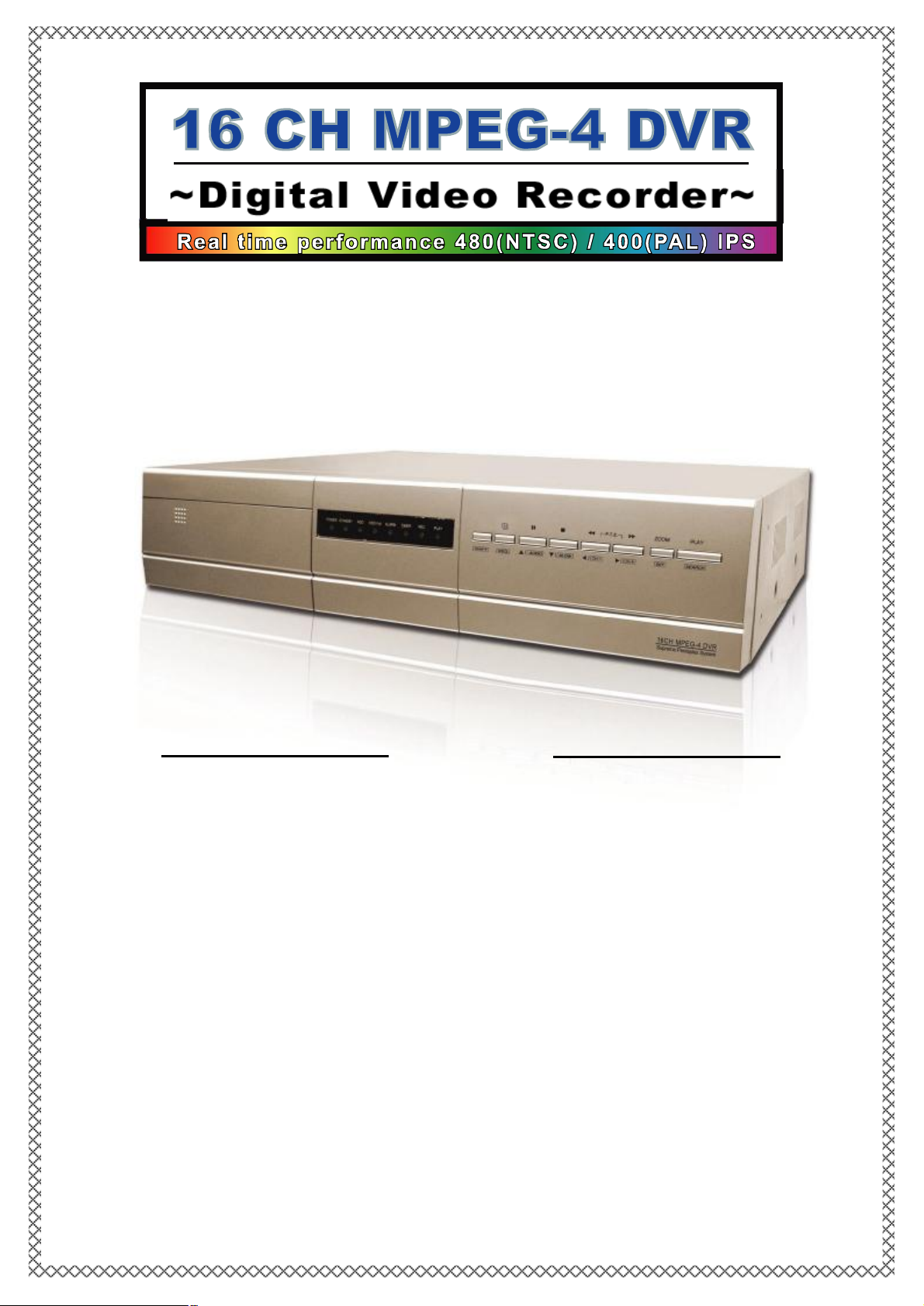
16 / 8 CH
16 / 8 CH
User’’
User
Please read instructions thoroughly before operation and retain it for future reference.
s Manual
s Manual
787 V0.97
Page 2

Thank-You Note Before You Get Start
First of all, we would like to express our gratitude to you for purchasing this product.
This product is designed to meet your personal needs with our great industry-designing
ability and our everlasting perseverance to the quality of all our products.
This manual will introduce to you how to install this apparatus.Please keep it well for
your future reference.
Now, we would like to invite you to personally experience all ofthe powerful functions
this product offers.
Note: Version: 1016-06-D3-04-V354-02; AP: 0013.
Note: Any changes of AP, please refer to your distributor.
Note: Any changes of this manual made to the actual product are subjects to no further notification.
Page 3
IMPORTANT SAFEGUARD
IMPORTANT SAFEGUARD
CAUTION
CAUTION
RISK OF ELECTRIC SHOCK
RISK OF ELECTRIC SHOCK
CAUTION:
CAUTION:
To reduce the risk of electric shock, do not expose this apparatus to rain or moisture.
Only operate this apparatus from the type of power source indicated on the label. Failure to do so
may cause injury or death by electric shock and invalidates the warranty.
The lightning flash with arrowhead symbol, within an equilateral
triangle, is intended to alert the user to the presence of uninsulated
“dangerous voltage” within the product’s enclosure that may be of
sufficient magnitude to constitute a risk of electric shock to persons.
This exclamation point within an equilateral triangle is intended to
alert the user to the presence of important operating and
maintenance (servicing) instructions in the literature accompanying
the appliance.
CE Mark
This apparatus is manufactured to comply with the radio interference
requirements of EN 55022 : 1998 + A1 : 200, EN61000-3-2 : 2000,
EN6100-3-3:1995, EN50130-4 : 1995 + A1 : 1998.
Page 4

TABLE OF CONTENTS
TABLE OF CONTENTS
PARTS AND FEATURES
PARTS AND FEATURES
1.1 FEATURES---------------------------------------------------------------------------------------------------------
1.2 PACKAGE CONTENTS -----------------------------------------------------------------------------------------
1.3 SPECIFICATION --------------------------------------------------------------------------------------------------
1.4 FRONT PANEL ----------------------------------------------------------------------------------------------------
1.5REAR PANEL ------------------------------------------------------------------------------------------------------
INSTALLATION AND CONNECTION
INSTALLATION AND CONNECTION
2.1 PHYSICAL CONNECTION --------------------------------------------------------------------------------------
2.2 GETTING STARTED ----------------------------------------------------------------------------------------------
ADVANCED DESIGN
ADVANCED DESIGN
3.1 MOTION DETECTION SETTING -----------------------------------------------------------------------------
3.2 QUICK EVENT SEARCH ---------------------------------------------------------------------------------------
BASIC OPERATION
BASIC OPERATION
4.1 RECORDING-------------------------------------------------------------------------------------------------------
4.2 PLAYBACK---------------------------------------------------------------------------------------------------------
1
1
2
4
6
8
9
10
11
11
12
DETAILED MENU CONFIGURATION
DETAILED MENU CONFIGURATION
5.1 MENU TREE------------------------------------------------------------------------------------------------------
5.2 ACCESS MENU--------------------------------------------------------------------------------------------------
5.3 MAIN MENU OPTIONS_ RECORD-------------------------------------------------------------------------
5.4 MAIN MENU OPTIONS_ TIMER -----------------------------------------------------------------------------
5.5 MAIN MENU OPTIONS_ DATE ------------------------------------------------------------------------------
5.6 MAIN MENU OPTIONS_ ADVANCE ------------------------------------------------------------------------
5.7 ADVANCE MENU_ CAMERA--------------------------------------------------------------------------------
5.8 ADVANCE MENU_ DETECTION----------------------------------------------------------------------------
5.9 ADVANCE MENU_ DISPLAY--------------------------------------------------------------------------------
5.10ADVANCE MENU_ ALERT-----------------------------------------------------------------------------------
5.11ADVANCE MENU_ REMOTE---------------------------------------------------------------------------------
5.12ADVANCE MENU_ SYSTEM---------------------------------------------------------------------------------
5.13 ADVANCE MENU_ NETWORK -------------------------------------------------------------------------------
5.14 ADVANCE MENU_ BACKUP ---------------------------------------------------------------------------------
5.15 ADVANCE MENU_ HDD INFO-------------------------------------------------------------------------------
5.16 ADVANCE MENU_ EVENT LOG ----------------------------------------------------------------------------
ADDITIONAL OPERATION
ADDITIONAL OPERATION
6.1 SEARCH-------------------------------------------------------------------------------------------------------------
6.2 2X DIGITAL ZOOM-----------------------------------------------------------------------------------------------
6.3 KEY LOCK ----------------------------------------------------------------------------------------------------------
6.4 SWITCH THE N/P SYSTEM ------------------------------------------------------------------------------------
6.5 USB UPGRADE----------------------------------------------------------------------------------------------------
6.6 LICENSED SOFTWARE AP------------------------------------------------------------------------------------
6.7 CONNECT TO AP VIA IE BROWSER -----------------------------------------------------------------------
6.8GPRS -----------------------------------------------------------------------------------------------------------------
6.9OPTIONAL PHERIPHERALS----------------------------------------------------------------------------------
13
14
15
16
17
18
18
19
21
22
23
24
25
26
27
27
28
29
29
29
30
30
44
46
46
TROUBLE SHOOTING
TROUBLE SHOOTING
7.1 FAQ-------------------------------------------------------------------------------------------------------------------
APPENDIX #1 INSTALL THE HDD ------------------------------------------------------------------
APPENDIX #1
APPENDIX #2 PIN CONFIGURATION -------------------------------------------------------------
APPENDIX #2
APPENDIX #3 IR TRANSMITTER -------------------------------------------------------------------
APPENDIX #3
APPENDIX #44 RECORDING TIME TABLE --------------------------------------------------------
APPENDIX #
47
48
49
50
55
Page 5
PARTS AND FEATURES
PARTS AND FEATURES
1.1 FEATURES
1.1 FEATURES
DVR Features
DVR Features
v MPEG-4 real time compression format
v High resolution recording (For 16 channels):
Frame: 720 × 480 pixels with 120 IPS〈NTSC〉/ 720 × 576 pixels with 100 IPS 〈PAL〉
Field: 720 × 240 pixels with 240 IPS〈NTSC〉/ 720 × 288 pixels with 200 IPS〈PAL〉
CIF: 352 × 240 pixels with 480 IPS〈NTSC〉/ 352 × 288 pixels with 400 IPS 〈PAL〉
v Image quality setting: Best, High, Normal, and Basic
v Extensive recording time by connected to Independent Disk Array.
v Remote surveillance on mobile phone via GPRS, or on PC through internet connection
v Easy file backup methods with USB, DVD R/W (optional), and CD R/W (optional)
v Alarm trigger recording will send alert with images to designated e-mail and FTP address
Also supports pre-alarm recording
v Advanced motion detection function (4 different adjustable factors of motion detection sensitivity) and convenient
search function.
v Support pre-alarm recording function
v Pentaplexfunctions (live display, record, playback, backup, and network)
v Web function supports MJPEG compression format for transmitting over the internet
v Web surveillance supports multiple viewers simultaneously
v Support covert screen for live view channels
v IR remote control of the system and PTZ through RS-485
v Support PELCO-D protocol
v 2 HDD bases built-in, each can support more than 400GB
v Easy system upgrade via USB
v Support static IP, dynamic IP, and DHCP with DDNS function
v Support manual / timer / motion / alarm recording functions
v Record audio with 4ch in and 2ch out
v Watermark function ensures authentication of recorded images
v System auto recovery after power reconnected
v Support SATA HDD
v Optional: DVD R/W / CD R/W backup; Independent disk array; VGA output; GPRS connector.
1.2 PACKAGE CONTENTS
1.2 PACKAGE CONTENTS
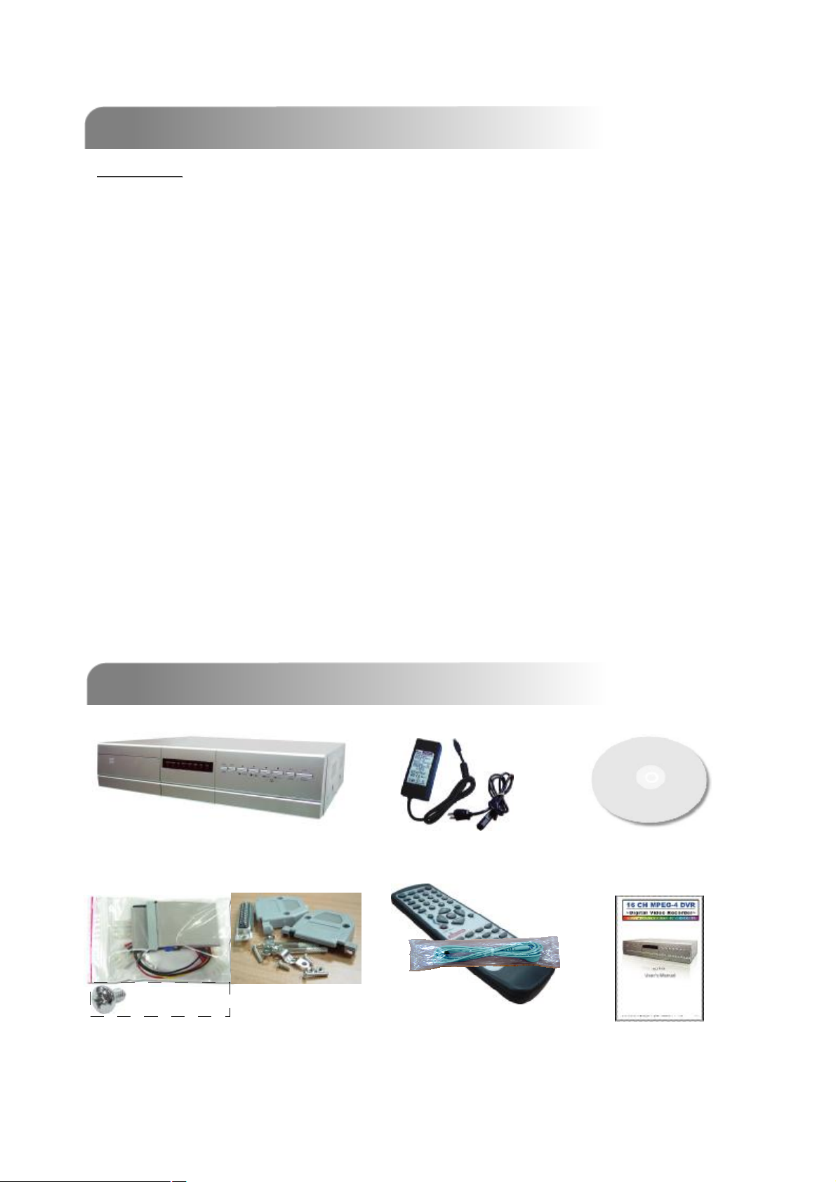
Digital Video Recorder
Adapter
* 8
Accessories Packs
IR Transmitter and
IR Receiver (1.5m)
Licensed Software AP
Manual & Quick Start
NOTE: Please check the package contents to make sure that you receive all accessories shown above.
1
Page 6

1.3 SPECIFICATION
2
1.3 SPECIFICATION
NTSC / PAL (switch able) Video System
MPEG 4Video Compression Format
16 / 8 Channels. Composite video signal 1 Vp-p 75Ω BNC Video Input
16 / 8 Channels. Composite video signal 1 Vp-p 75Ω BNC Video Loop Out
Video Output
Maximum Recording Rate
Adjustable Recording Speed
Main Monitor Output: Composite video signal 1 Vp-p 75Ω BNC
Call Monitor Output: Composite video signal 1 Vp-p 75Ω BNC
16 channels ~
Frame: 720 × 480 pixels with 120 IPS〈NTSC〉/ 720 × 576
pixels with 100 IPS 〈PAL〉
Field: 720 × 240 pixels with 240 IPS〈NTSC〉/ 720 × 288
pixels with 200 IPS 〈PAL〉
CIF: 352 × 240 pixels with 480 IPS〈NTSC〉/ 352 × 288
pixels with 400 IPS 〈PAL〉
8 channels ~
Frame: 720 × 480 pixels with 60 IPS〈NTSC〉/ 720 × 576
pixels with 50 IPS 〈PAL〉
Field: 720 × 240 pixels with 120 IPS〈NTSC〉/ 720 × 288
pixels with 100 IPS 〈PAL〉
CIF: 352 × 240 pixels with 240 IPS〈NTSC〉/ 352 × 288
pixels with 200 IPS 〈PAL〉
16 channels ~
Frame: 120, 60, 30, 15 IPS <NTSC> / 100, 50, 25, 13 IPS <PAL>
Field: 240, 120, 60, 30 IPS <NTSC> / 200, 100, 50, 25 IPS <PAL>
CIF: 480, 240, 120, 60 IPS <NTSC> / 400, 200, 100, 50 IPS <PAL>
8 channels ~
Frame: 60, 30, 15, 7 IPS <NTSC> / 50, 25, 12, 6 IPS <PAL>
Field: 120, 60, 30, 15 IPS <NTSC> / 100, 50, 25, 12 IPS <PAL>
CIF: 240, 120, 60, 30 IPS <NTSC> / 200, 100, 50, 25 IPS <PAL>
Best, high, normal, and basicImage Quality Setting
Hard Disk Storage
HDD Quick Cleaning
Refresh Rate
PentaplexOperation
IDE type, ATA66, supported HDD * 2, support each HDD capacity
over 400GB
Quick clean up the “index system” of the recorded files.
250GB under 2 seconds
Yes (Ready in September, 2005)Support SATA HDD
Manual/Timer/Motion/AlarmRecording Mode
Yes (Ready in September, 2005)Watermark
16 channels: 480 IPS for NTSC /
400 IPS for PAL
Pentaplexfunctions (live display, record, playback, backup, and
network)
4 audio inputs, 2 audio outputs (Mono) Audio I/O
8 channels: 240 IPS for NTSC /
200 IPS for PAL
Page 7

Specification Continued…
Format
16 × 12 grid per camera for all channelsMotion Detection Area
4 adjustable variable with precise calculation for motion detectionMotion Detect Sensitivity
Yes (Ready in September, 2005)Pre-alarm Recording
USB1.1 Backup, and network remote backupBackup Device
Motion JPEGWeb Transmitting Compression
Ethernet
Mobile Surveillance
Remote Alarm Notification
Switch)
Alarm I/O
10/100 Base-T. Support remote control and live view via
Ethernet.
Support GPRS to access the system via mobile phone (require
J2ME, MIDP2.0 protocol)
Support licensed software AP, and IE browser Web Interface
E-mail images, and images uploading to FTP site’s specific
account
Support static IP, dynamic IP, and DHCP with DDNS functionNetwork Connection
Support 2 USB 1.1 ports (front panel * 1, back panel * 1)USB Interface
Remote control DVR and PTZ via IR transmitter (RS-485)Remote Control
Support PELCO-D protocol (Ready in September, 2005)PTZ control
Programmable with adjustable dwell time Dwell Time (Sequential Channel
16 channels:
16 inputs, 1 outputs
Support 2X digital zoom function Picture Zoom
8 channels:
8 inputs, 1 outputs
Yes Key Lock
YesVideo Loss Detection
Support up to 6 letters Camera Title
Hue/Color/Contrast/ Brightness Video Adjustable
YY/MM/DD, DD/MM/YY, MM/DD/YY, and Off Date Display Format
DC 19VPower Source
<64 W Current Consumption
10℃ ~ 40℃ (50℉~104℉)Operating Temperature
432mm (W) × 90mm (H) × 326mm (D) Dimensions (mm)
System auto recovery after power reconnectedSystem Recovery
Optional Peripherals
q Any changes made to the actual product are subjects to no further notification.
DVD R/W backup / CD R/W backup; Independent disk Array;
VGA output; GPRS connector (Ready in September, 2005)
3
Page 8
1.4 FRONT PANEL
1.4 FRONT PANEL
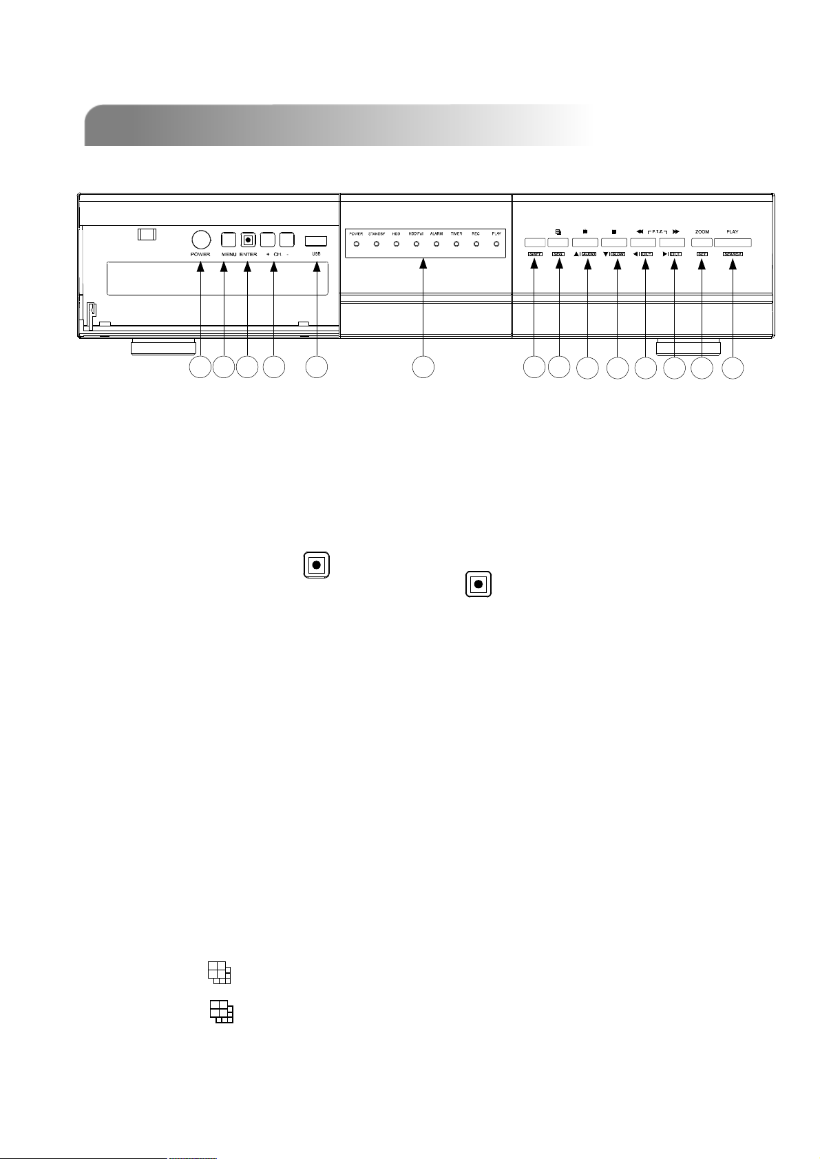
a b c d e f g h
1) POWER: (a)
Press POWER button to turn on/ turn off the DVS.
(Under recording mode, please stop record before turn off the DVS)
2) MENU: (b)
Press MENU button to enter main menu.
3) ENTER / RECORD : (c)
Press ENTER button to confirm. / Press “ ” to activate the manual recording.
4) “+ CH - ”: (d)
Press “+ CH - ” button to change the setting in the menu / to select the channel.
5) USB: (e)
Support firmware update and files backup.
6) LED LIGHT: (f)
POWER: Power on
STANDBY: Standby
HDD: HDD is reading or recording
HDD Full: HDD is full.
ALARM: Once the alarm is triggered
TIMER: When timer recording is turned on.
REC: Under recording status
PLAY: Under playing status
i j k l m n
7) MODE : (h)
Press “ ” button to switch channel display mode (16, 9, 4 channels display
mode, and show the switch display by each channel)
4
Page 9
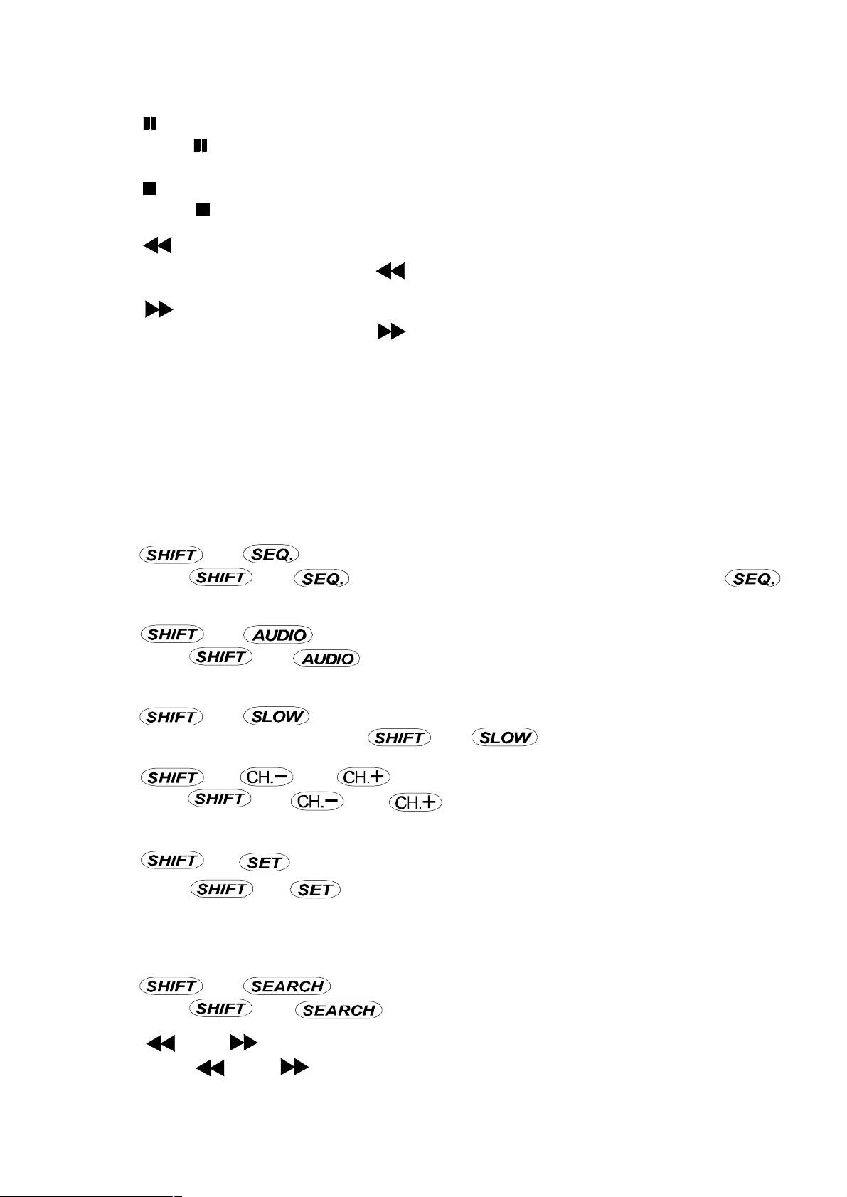
8) “ ”: (i)
Press “ ” button to pause the play back files.
9) “ ”: (j)
Press “ ” button to stop the play back files.
10) “ “: (k)
Under playback mode, press “ ” button to fast rewind.
11) “ “: (l)
Under playback mode, press “ ” to fast forward.
12) “ZOOM”: (m)
Press “ZOOM” button to enlarge the picture of selected channel (2X digital zoom).
13) “PLAY” : (n)
Press “PLAY” button to playback recorded files.
▲
▲
▲
▲
▲
14) “ “: (i), (j), (k), (l)
▲
Press “ ” to move the cursor up / down / left / right.
▲
▲
15) “ ” + “ ” : (g +h)
Press “ ” + “ ”to activate the call monitor function and press “ ”
to escape the call monitor mode.
16) “ ” + “ “ : (g+i)
Press “ ” + “ “ to select live or playback sounds of the 4 audio
channels.
17) “ ” + “ “ : (g+j)
Under playback mode, press “ ” + “ “ to show slow playback.
18) “ ” + “ “ or “ ”: (g+k) or (g+l)
Press “ ” + “ “ or “ ” change the setting in the menu / to select the
channel.
19) “ ” + “ ” : (g+m)
Press “ ” + “ ” to change channel display position.
Press “ ” to select the channel which You would like to change,
Press “+” or “-” select the channel which You would like show.
Press “ENTER” button to confirm.
▲
▲
▲
▲
20) “ ” + “ ”: (g+n)
Press “ ” + “ ” button to enter the search mode.
21) “ ” + “ ”: (k+l)
Press “ ” + “ ” buttons at the same time to enter the PTZ control mode.
5
Page 10
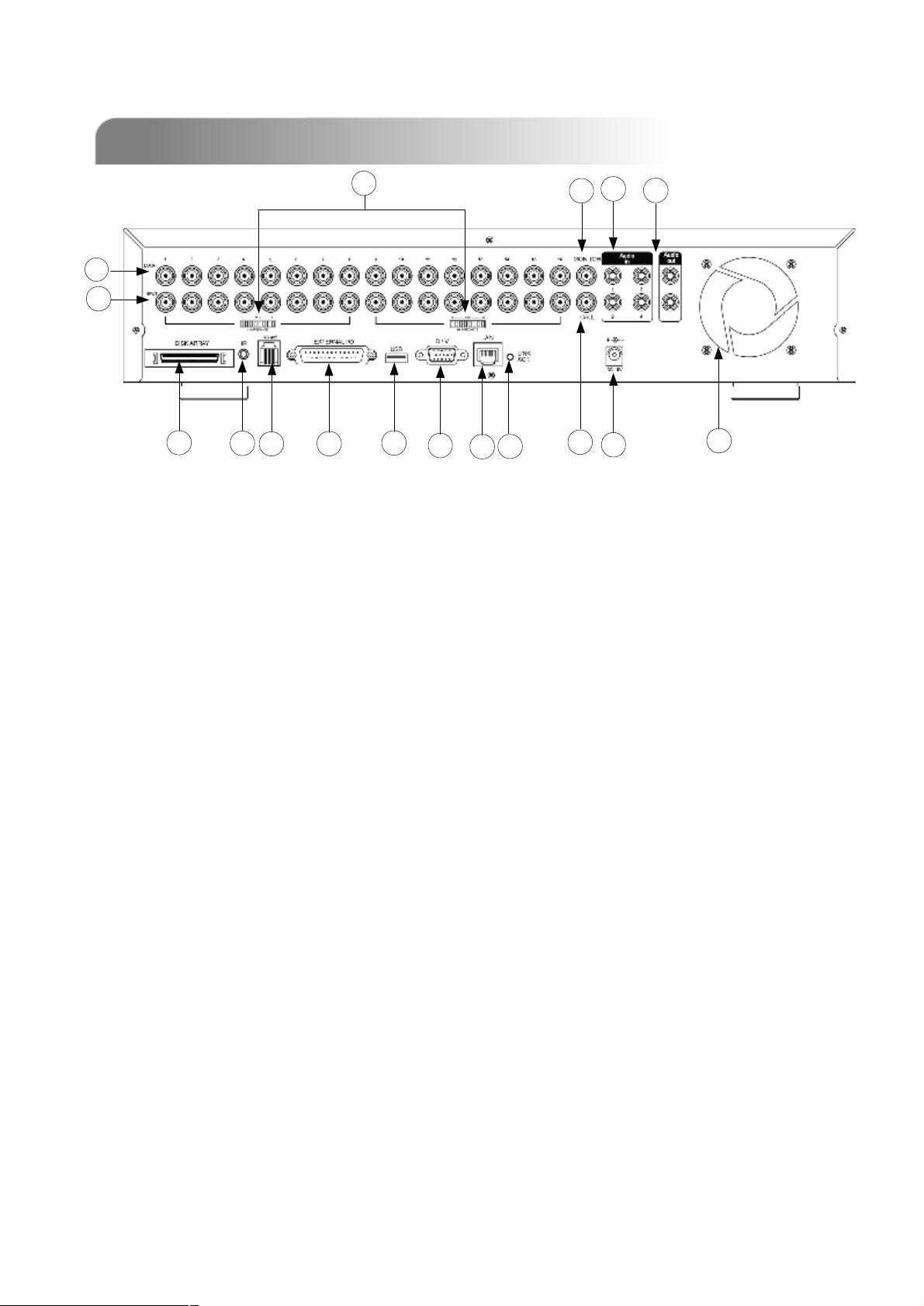
1.5 REAR PANEL
1.5 REAR PANEL
13
12
1
2
3 4
1) DISK ARRAY PORT:
Connect to disk array for extend HDD capacity.
2) IR:
Connect to IR receiver.
14
16
10
17
11
15
5
6
8
7
9
3) RS485:
Connect to external device (such as PTZ camera) with RS485-A and RS485-B.
4) EXTERNAL I/O PORT:
Connect to external device. Control external device or controlled remotely by
external device. Alarm input, external alarm.
5) USB PORT:
Support firmware update and files backup.
6) D/V PORT (Digital Video Port):
Connect to VGA connector card.
7) LAN:
Connect to Internet by LAN cable.
8) LINK / ACT LED light:
When the Internet is activated, the LED light will turn on.
CALL MONITOR:
9)9)CALL MONITOR:
Connect to CALL monitor. Show the Switch Display. When the alarm
Connect to CALL monitor. Show the Switch Display. When the alarm
triggered, the call monitor will show the triggered channel for
triggered, the call monitor will show the triggered channel for
6
is
is
a period of time.
a period of time.
Page 11

10)POWER:
Connect to provided Adapter.
11)FAN:
For ventilation.
12)VIDEO INPUT (CHANNEL 1 -16 / CHANNEL 1 -8) :
Connect to video source, such as camera.
13)LOOP (CHANNEL 1 -16 / CHANNEL 1 -8):
Video output.
14)75Ω / HI:
When using Loop function, please switch to HI. When you don’t use Loop
function, please switch to 75Ω.
15)MONITOR:
Connect to Main monitor.
16)AUDIO IN (1-4):
Connect to audio source, such as microphone.
4 audio inputs, but users can only select 1 for recording.
17)AUDIO OUT :
Connect to monitor or speaker.
With 2 mono audio outputs from the same source.
7
Page 12
INSTALLATION AND CONNECTION
INSTALLATION AND CONNECTION
2.1 PHYSICAL CONNECTION
2.1 PHYSICAL CONNECTION
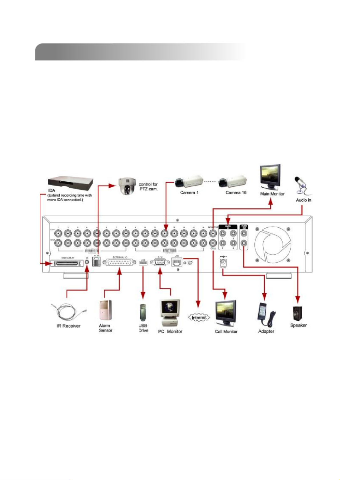
1) Install HDDs.
2) Please refer to
The HDDsmust be installed before the DVR is turned on.
3) The illustration below will show you how to connect cameras and monitor to DVR.
4) Connecting the DVR to your existing surveillance system, as shown below.
(For 16 channels.)
(For 16 channels.)
Appendix #1 for installation instructions.
Appendix #1
8
Page 13
2.2 GETTING STARTED
2.2 GETTING STARTED
1) Before using the DVR, please have the HDDsinstalled ready.
#1 for installation of
#1 for installation of
HDDs)).
HDDs
(refer to Appendix
(refer to Appendix
2) Connect the AC Power Cord to Power Adapter and plug into an electrical outlet.
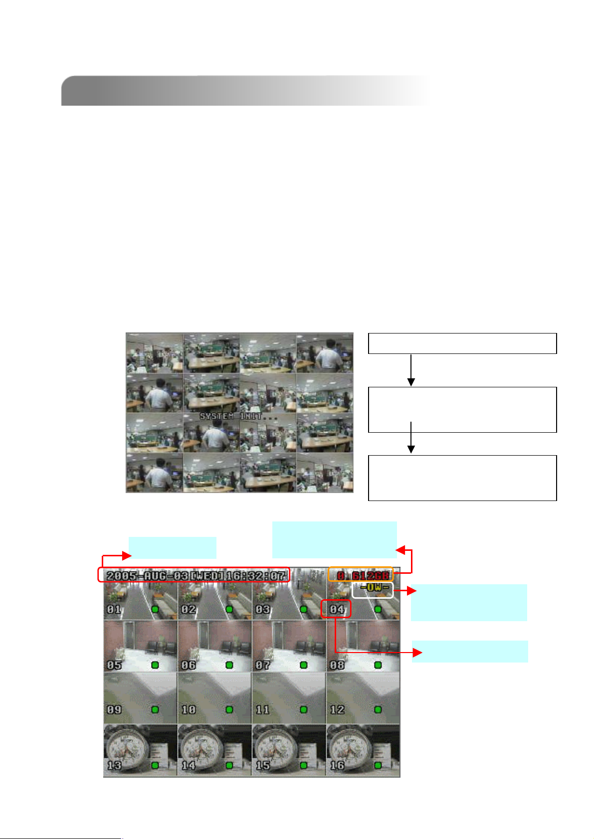
The Standby LED light will turn to red.
Press the Power button. The POWER LED will be red. It takes approximately 10
to 15 seconds to boot the system with the message : “ SYSTEM INIT. ”, “HDD
DETECTING”, and “HDD DETECTED”.
3) Before operating the DVR, please set up the system time first.
system time, please refer to ““
system time, please refer to
DATE””
DATE
settings).
settings).
SYSTEM INIT…
DETECTING MASTER HDD OK
DETECTING SLAVE HDD FAIL
DETECTING DISKARRAY FAIL
(for setting
(for setting
System Time
Available Capacity
of Internal HDDs
VERSION 1016-06-D3-04-V354-02
SYSTEM NTSC
-787 -
Under HDD
Overwrite Mode
Channel Title
NOTE :
When “HDD not found”
message shows up,
please refer to
# 1. It may result from
# 1
the improper installation
of the HDD.
appendix
appendix
9
Page 14

ADVANCED DESIGN
ADVANCED DESIGN
“Advanced Motion Detection Setting” allows users to adjust different sensitivity factors
base on different environment. And “Quick Event Search” allows users to examine the
setting of motion detection factors. In this way, users can use specific motion detection
setting to capture every important image.
3.1 MOTION DETECTION SETTING
3.1 MOTION DETECTION SETTING
q LS : The sensitivity of comparing two different images.The smaller the value is,
the more sensitive the detection will become.
Application ~
* Environment vibration * Light shift
* Shadow * Mirror reflection
q SS : The sensitivity towards the size of the triggered object on the screen.The
smaller the value is, the more sensitive the detection will become.
Application ~
* Different size of the objecton the screen.
q TS : The sensitivity towards how long the object gets triggered. The smaller the
value is, the more sensitive the detection will become.
Application ~
* Differentspeed of the moving object
q RE : The value of RE is a reference for detection. The default value is 10, which
means DVR will compare 10 continuous images at one time according to the
sensitivity of LS, SS, TS simultaneously. Therefore the bigger the value is, the
more sensitivity the detection will become.
Application ~
* Slow and regular environment change
Scenario : Warehouse
Different environments may require different settings, the sample below is for
your reference.
LS
LS
SS
SS
TS
TS
RE
RE
102210Entrance
10218Back door
10225Sidewalk
1010212Widow
v Note 1 : The real appropriate setting value will depend on the real situation
(such as the angle of the lens, the distance between the camera and
object…etc.)
v Note 2 : User could also refer to “Section 5.8 Advance Menu_Detection” for
detail setting.
10
Page 15
3.2 QUICK EVENT SEARCH
3.2 QUICK EVENT SEARCH
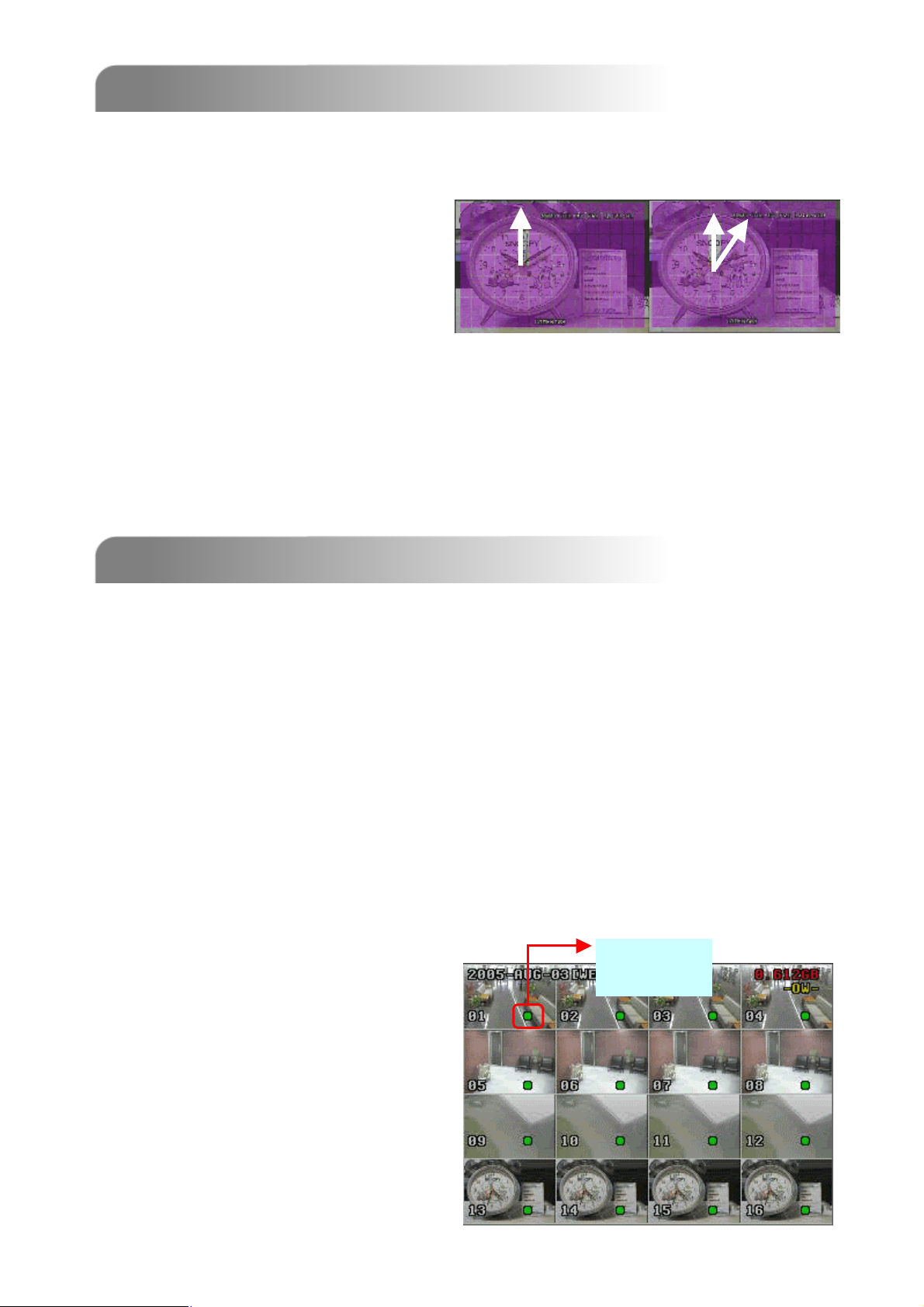
When finishing the setup of the motion detection, users could simply use the quick
event search to examine the setting. There is a simple example for you to understand
the principle.
For example, Motion detection
area: see as the following illustration
picture.Motion detection
factors: LS:10; SS:1; TS:3; RE:10
Alarm duration: 5 seconds.
After recording for a period of time, users could use quick event search to playback
the motion trigger recording files, then users will see the
between
the number ““1212””
the number
and ““11””
and
on the clock.
on the clock
second handsswing
second hands
BASIC OPERATION
BASIC OPERATION
4.1 RECORDING
4.1 RECORDING
The DVS offers three recording modes, manual record, event recording, and timer
record. If power is off accidentally, recorded video files will still be stored in the HDDs.
DVS will return to original recording status after power is on again.
q MANUAL RECORDING (continuous recording) :
Recording is initiated by manually pressing the REC button.
Indicated by the sign “●”
q EVENT RECORDING (triggered by motion and external alarm) :
When this functions is activated,
the recording is triggered by motion or external alarm.
Indicated by the sign “M” and “A” .
q TIMER RECORDING (scheduled time) :
Recording is scheduled by Timer. Indicated by the sign “TIMER RECORD”.
Under
NOTE :
When the HDDsare full under O/W
Recording
Recording mode, previous recorded
files may beoverwritten without
further warning notices.
11
Page 16
4.2 PLAYBACK
4.2 PLAYBACK
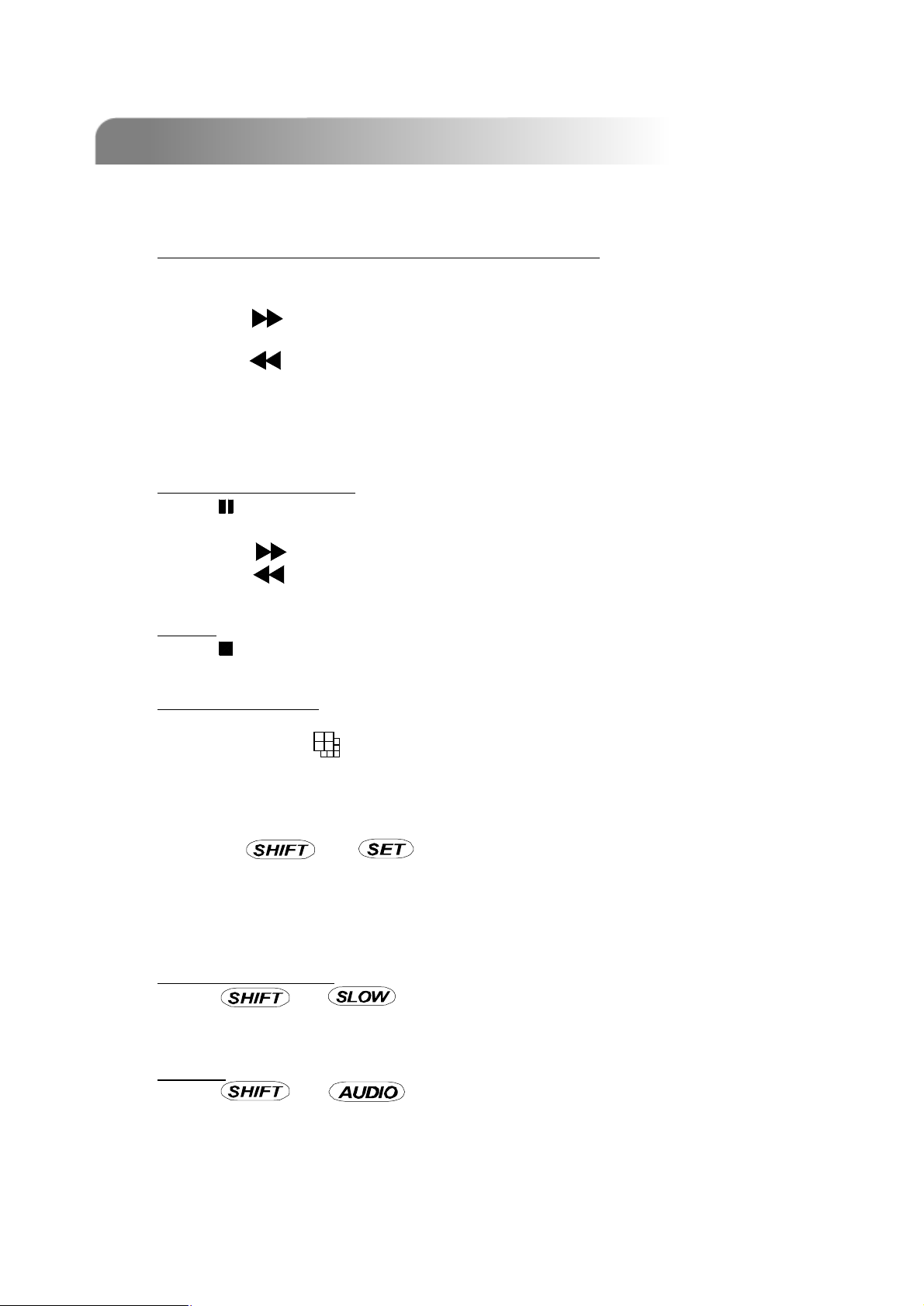
Press “ PLAY ” button, the DVS will display the last recording video.
1) FAST FORWARD (F.F. ) & FAST REWIND (REW):
You can increase speed for Fast Forward and Rewind on the DVS.
In the Playback mode,
* Press ” ” once to get 4X speed forward and press twice to get 8X speed,…
and the maximum speed can reach 32X.
* Press ” ” once to get 4X speed rewind and press twice to get 8X speed, …
and the maximum speed can reach 32X.
* The type of recording image size (Frame, Field, or CIF )will also shown on the
screen.
2) PAUSE / IMAGE JOG:
Press “ ” button to pause the current image displayed on the screen.
In the Pause mode,
* Press ” ” once to get forward by frame change.
* Press ” ” once to get rewind by frame change.
3) STOP:
Press “ ” button under all circumstance, it will return DVS to live monitoring mode.
4) CHANNEL SHIFT:
* Display mode:
Press MODE “ ” button to select display mode (16 / 9 / 4 channels).
* Full Screen Switch:
Press “+” or “-” button to show the full screen channels.
* Channel display switch:
Press “ ” + “ ”button,
Press “▲”“▼”“ ”“ ”to select the channel which You would like to change.
Press “+” or “-” select the channel which You would like show.
Press “ENTER” button to confirm.
5) SLOW PLAYBACK:
Press “ ” + “ ” button to get 1/4X speed playback and press twice to
get 1/8X speed, three times to get 1/16X speed, and four times to get 1/32X sped.
6) AUDIO:
Press “ ” + “ “ to select live sounds of the 4 audio channels.
* AUDIO 1 (L)、 AUDIO 1 (P )
* AUDIO 2 (L)、 AUDIO 2 (P )
* AUDIO 3 (L)、 AUDIO 3 (P )
* AUDIO 4 (L)、 AUDIO 4 (P )
▲
▲
12
Page 17
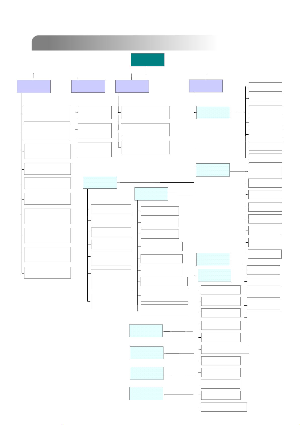
5.1 MENU TREE
5.1 MENU TREE
RECORD
RECORD
MANUAL RECORD
MANUAL RECORD
ENABLE
ENABLE
EVENT RECORD
EVENT RECORD
ENABLE
ENABLE
TIMER RECORD
TIMER RECORD
ENABLE
ENABLE
OVERWRITE
OVERWRITE
TIMER
TIMER
DATE
DATE
START
START
HH : MM
HH : MM
END
END
HH : MM
HH : MM
DETAILED MENU CONFIGURATION
DETAILED MENU CONFIGURATION
MENU
MENU
ADVANCE
DATE
DATE
DATE:
DATE:
YEAR MONTH DAY
YEAR MONTH DAY
TIME:
TIME:
HOUR MIN SEC
HOUR MIN SEC
FORMAT: Y--MM--D D ……
FORMAT: Y
ADVANCE
CAMERA
CAMERA
DETECTION
DETECTION
TITLE
TITLE
BRIG
BRIG
CONT
CONT
SATU
SATU
HUE
HUE
COV
COV
REC
REC
TITLE
TITLE
RECORD IMG SIZE
RECORD IMG SIZE
RECORD QUALITY
RECORD QUALITY
MANUAL RECORD
MANUAL RECORD
IPS
IPS
EVENT RECORD
EVENT RECORD
IPS
IPS
TIMER RECORD
TIMER RECORD
IPS
IPS
TOTAL IPS SHARE
TOTAL IPS SHARE
DISPLAY
DISPLAY
TITLE DISPLAY
TITLE DISPLAY
DATE DISPLAY
DATE DISPLAY
HDD INFO
HDD INFO
LOSS SCREEN
LOSS SCREEN
PLAYBACK
PLAYBACK
INFO
INFO
DWELL
DWELL
DURATION
DURATION
(SEC)
(SEC)
-
DEDE-
INTERLACE
INTERLACE
ALERT
ALERT
EXT. ALERT
EXT. ALERT
INT. BUZZER
INT. BUZZER
KEY BUZZER
KEY BUZZER
VLOSS BUZZER
VLOSS BUZZER
MOTION BUZZER
MOTION BUZZER
ALARM BUZZER
ALARM BUZZER
HDD BUZZER
HDD BUZZER
HDD NEARLY FULL
HDD NEARLY FULL
(GB)
(GB)
ALARM DURATION
ALARM DURATION
(SEC)
(SEC)
NETWORK
NETWORK
REMOTE
REMOTE
SYSTEM
SYSTEM
SERIAL TYPE
SERIAL TYPE
BAUD RATE
BAUD RATE
HOST ID
HOST ID
IR
IR
PASSWORD
PASSWORD
DET
DET
AREA
AREA
LS
LS
SS
SS
TS
TS
RE
RE
ALARM
ALARM
TITLE
TITLE
DEVICE
DEVICE
ID
ID
PROTOCOL
PROTOCOL
RATE
RATE
BACKUP
BACKUP
HDD INFO
HDD INFO
EVENT LOG
EVENT LOG
13
RESET DEFAULT
RESET DEFAULT
CLEAR HDD
CLEAR HDD
UPGRADE
UPGRADE
LANGUAGE
LANGUAGE
VERSION
VERSION
VIDEO FORMAT
VIDEO FORMAT
Page 18

5.2 ACCESS MENU
5.2 ACCESS MENU
Press “MENU” button to enter the main menu list. The default password is 0000.
Enter the default password and press “ENTER”. (You can alter the password later)
* 0000 : press “ENTER” four times.
* Press “+” or “-” to select the numbers (from 0 to 9).
(MENU)
RECORD
TIMER
DATE
ADVANCE
Use the following buttons for menu setting:
▲
“ “ to move the cursor.
“+ , -” to choose the numbers / selections.
“ ENTER “ to go to the submenu / to confirm the selection
“ MENU “ to go tothe menu OSD
▲
▲
▲
There are 4 options available in the Main Menu:
RECORD --------Record mode setup.
TIMER -----------Timer recording setup.
DATE -------------System date setup.
ADVANCE -------Advance Functions setup.
/ to confirm the change / to exit the menu OSD
14
Page 19

5.3 MAIN MENU OPTIONS___RECORD
5.3 MAIN MENU OPTIONS___RECORD
(MENU)
►
RECORD
RECORD
TIMER
DATE
ADVANCE
Move the cursor to the “RECORD”, and press ”ENTER”, then the screen will show the
following options.
RECORD
RECORD
MANUAL RECORD ENABLE
EVENT RECORD ENABLE
TIMER RECORD ENABLE
OVERWRITE
RECORD IMG SIZE
RECORD QUALITY
MANUAL RECORD IPS
EVENT RECORD IPS
TIMER RECORD IPS
TOTAL IPS SHARE
1) MANUAL RECORD ENABLE:
Start / Stop the manual recording function.
2) EVENT RECORD ENABLE:
Start / Stop the event recording function. When this functions is activated,
the recording will triggered by motion or external alarm
3) TIMER RECORD ENABLE:
Start / Stop the timer recording function.
4) OVERWRITE:
Select to overwrite previous recording video in HDD. When the HDD is full
under O/W recording mode, previous recorded files will be overwritten
without further warning notices.
5) RECORD IMG SIZE:
There are three recording options: FRAME, CIF & FIELD. When changing
record image size, user need to stop recording first.
6) RECORD QUALITY:
There are four quality settings: BEST, HIGH, NORMAL & BASIC
In the following (7) ~ (10) sections is for 16 channels. For 8 channels, divided the IPS by 2.
7) MANUAL RECORD IPS:
Recording is activated by pressing the “REC” button. Select the images per
second of MANUAL RECORD, The options are as the followings:
NTSC: FRAME: 120, 60, 30, 15
NTSC
FIELD: 240, 120, 60, 30 FIELD: 200, 100, 50, 25
CIF: 480, 240, 120, 60 CIF: 400, 200, 100, 50
15
PAL: FRAME: 100, 50, 25, 12
PAL
Page 20

8) EVENT RECORD IPS:
Recording is activated by event (alarm and motion trigger). Select the
images per second of EVENT RECORD, The options are as the followings:
NTSC: FRAME: 120, 60, 30, 15
NTSC
FIELD: 240, 120, 60, 30 FIELD: 200, 100, 50, 25
CIF: 480, 240, 120, 60 CIF: 400, 200, 100, 50
9) TIMER RECORD IPS:
Recording is activated by timer schedule. Select the images per second of
TIMER RECORD, The options are as the followings:
NTSC: FRAME: 120, 60, 30, 15
NTSC
FIELD: 240, 120, 60, 30 FIELD: 200, 100, 50, 25
CIF: 480, 240, 120, 60 CIF: 400, 200, 100, 50
10) TOTAL IPS SHARE:
There are two IPS settings:
FIX: IPS per channel = RECORD IPS ÷ 16 channels
FIX
GROUP: every 4 channels will form a group.
GROUP
IPS per channel = RECORD IPS ÷ 4 ÷ number
of channels under recording within the group.
Ex.: If you set the record IPS as 480 IPS, then
Channel 01 will get 120 IPS (480 / 4 / 1 = 120)
Channel 05 and 06 each will get 60 IPS (480 / 4 / 2 = 60)
“ ● “ means under recording
PAL: FRAME: 100, 50, 25, 12
PAL
PAL: FRAME: 100, 50, 25, 12
PAL
●
01
●
05
●
06
Group 1 :
CH 01 ~ 04
Group 2 :
CH 05 ~ 08
Group 3 :
CH 09 ~ 12
Group 4 :
CH 13 ~ 16
5.4 MAIN MENU OPTIONS___TIMER
5.4 MAIN MENU OPTIONS___TIMER
(MENU)
RECORD
►
TIMER
TIMER
DATE
ADVANCE
Move the cursor to the “TIMER”, and press ”ENTER”, then the screen will show the
following options.
TIMER
TIMER
DATE HH : MM HH : MM
OFF 00 : 00 00 : 00
DAILY 08 : 00 18 : 00
SUN 06 : 00 23 : 00
MON-FRI00 : 00 00 : 00
OFF 00 : 00 00 : 00
OFF 00 : 00 00 : 00
OFF 00 : 00 00 : 00
16
Page 21

1) DATE:
Select the day, or days of the week (SUN/MON/TUE/ WED/ THU/ FRI/SAT/
MON–FRI / SAT-SUN / DAILY/OFF) that you plan to schedule the DVR to
auto recording.
NOTE 1 : Specific date could be changed by “+” or “-” buttons.
NOTE 2 :If you plan to set the timer recording across the midnight, there are
two ways for setting the timer recording schedule, please following the
instructions below.
Example 1 : If you only want to set recording timer schedule from every
Sunday 23:30 to Monday 23:30, then you could set Recording TimerSchedule
as Sunday from 23:30 to 23:30.
Example 2 : If you plan to set the timer recording from Sunday 08:00 to
Monday 15:00, then you could set the recording timer schedule asSunday
from 08 : 00 to 00 : 00, and Monday 00 : 00 to 15 : 00.
2) START HH / MM:
Select the start time for the recording.
3) END HH / MM:
Select the finishing time for the recording.
5.5 MAIN MENU OPTIONS___DATE
5.5 MAIN MENU OPTIONS___DATE
(MENU)
RECORD
TIMER
►
DATE
DATE
ADVANCE
Move the cursor to the “DATE”, and press ”ENTER”, then the screen will show the
following options.
DATE
DATE
DATE YEAR MONTH DAY
2005 MAY 30
TIME HOUR MIN SEC
15 30 18
FORMATY-M-D
Set the correct time of the DVR.
There are three FORMAT of date: Y-M-D, M-D-Y, D-M-Y.
NOTE: Press “+”“-”button to do the selections.
17
Page 22

5.6 MAIN MENU OPTIONS___ADVANCE
5.6 MAIN MENU OPTIONS___ADVANCE
(MENU)
RECORD
TIMER
DATE
►
ADVANCE
ADVANCE
Move the cursor to the “ADVANCE”, and press ”ENTER”, then the screen will show
the following options.
ADVANCE
ADVANCE
CAMERA
DETECTION
DISPLAY
ALERT
REMOTE
SYSTEM
NETWORK
BACKUP
HDD INFO
EVENT LOG
5.7 ADVANCE MENU ___CAMERA
5.7 ADVANCE MENU ___CAMERA
Move the cursor to the “CAMERA”, and press ”ENTER”, then the screen will show the
following options.
CAMERA
CAMERA
TITLE BRIG CONT SATU HUE COV REC
01 128 128 128 128 NO YES
02 128 128 128 128 NO YES
03 128 128 128 128 NO YES
04 128 128 128 128 NO YES
05 128 128 128 128 NO YES
06 128 128 128 128 NO YES
07 128 128 128 128 NO YES
08 128 128 128 128 NO YES
UP DOWN
18
Page 23

1) TITLE:
Move the cursor to the title which you want to change the title,and press
“ENTER” to go in the setting screen. Assign each channel a title (up to six
characters (letters or symbols…)), the default title is the channel number.
2) BRIG / CONT / SATU / HUE:
Adjust the Brightness/Contrast/Saturation/Hue of each channel.
The level is from 0 to 255. The default value is 128.
3) COV (COVERT):
Select “YES” to mask the selected channel which is under recording.
4) RECORD:
Select “YES” to enable the record function; Select “NO” to disable the record
function.
5) UP / DOWN:
Select “UP” to go to the previous page; Select “DOWN” to go the next page.
NOTE:
TITLE : 6 characters (letters or symbols…).
BRIG : from 0 ~ 255, the default value is 128.
CONT : from 0 ~ 255, the default value is 128.
SATU : from 0 ~ 255, the default value is 128.
HUE : from 0 ~ 255, the default value is 128.
CONV : YES or NO.
REC : YES or NO.
5.8 ADVANCE MENU ___DETECTION
5.8 ADVANCE MENU ___DETECTION
Move the cursor to the “DETECTION”, and press ”ENTER”, then the screen will show
the following options.
DETECTION
DETECTION
TITLE DET AREA LS SS TS RE ALARM
01 ON SETUP 07 03 02 10 OFF
02 ON SETUP 07 03 02 10 LOW
03 ON SETUP 07 03 02 10 HIGH
04 ON SETUP 07 03 02 10 OFF
05 ON SETUP 07 03 02 10 OFF
06 ON SETUP 07 03 02 10 OFF
07 ON SETUP 07 03 02 10 OFF
08 ON SETUP 07 03 02 10 OFF
UP DOWN
19
Page 24

1) TITLE:
Show the title of each channel of the camera.
2) DET:
Select “ON” to activate the motion detect function of each channel.
Select “OFF” to inactivate the motion detect function of each channel.
3) AREA:
Press the “ENTER” button to set detection area.
In this function, the default setting is un-detecting any area. Pink blocks
represent the area that is not being detected. While the transparent blocks is
the area that is under detection.
Press “ENTER” to confirm
the start area
You can have multidetected area
▲
4) LS :
▲
▲
▲
The sensitivity of comparing two different images. The smaller the value
is, the higher sensitivity for motion detection.
The highest sensitivity setting is 00, the lowest sensitivity setting is 15.
The default value is 07.
: navigates between targets.
▲
Press or to choose
the width of the area
Press “-” to turn all
area under detection
▲
Press ▲ or ▼ to choose
the height of the area,
and press “ENTER”
again to confirm.
Press “+” to turn all
area not to be detected
5) SS :
The sensitivity towards the size of the triggered object on the screen.(the
number of motion detection grids). The smaller the value is, thehigher
sensitivity for motion detection.
The highest sensitivity setting is 00, and the lowest sensitivity setting is
15. The default setting is 03.
Note: The default setting of Spatial Sensitivity is 03, which means when 3 grids
are detected for motion at one time, the system will get triggered. So the
value of Spatial Sensitivity must be less than the number of grids which
you set up to motion detection area.
20
Page 25

6) TS :
The sensitivity towards how long the object gets triggered. The smaller the
value is, the higher sensitivity for motion detection.
The highest sensitivity setting is 00, and the lowest sensitivity setting is 15.
The default setting is 02.
7) RE :
The value of RE is a reference for detection. The default value is 10, which
means DVR will compare 10 continuous images at one time according to the
sensitivity of LS, SS, TS simultaneously. Therefore the bigger the value is, the
higher sensitivity for motion detection.
8) ALARM:
Select LOW / HIGH for the alarm polarity. The default alarm value is OFF.
9) UP / DOWN:
Select “UP” to go to the previous page; Select “DOWN” to go the next page.
Targets set in the AREA.
5.9 ADVANCE MENU ___DISPLAY
5.9 ADVANCE MENU ___DISPLAY
Move the cursor to the “DISPLAY”, and press ”ENTER”, then the screen will show the
following options.
DISPLAY
DISPLAY
TITLE DISPLAY ON
DATE DISPLAY ON
HDD INFO ON
LOSS SCREEN BLUE
PLAYBACK INFO NORMAL
DWELL DURATION (SEC) 2
DE-INTERLACE ON
1) TITLE DISPLAY:
Turn the camera title display on / off.
2) DATE DISPLAY:
Turn the date display on / off.
3) HDD INFO”
Turn the information of internal HDD and DISK ARRAY display on /off.
4) LOSS SCREEN”
Set the color of video loss screen (Blue or Black)
5) PLAYBACK INFO:
Set the position where PLAYBACK INFO will be indicated (center or normal (on the
button of left-hand side of the screen)).
21
Page 26

6) DWELL DURATION (SEC):
Set the duration time of each camera for CALL MONITOR (2, 4, 8, 16 sec.)
7) DE-INTERLACE:
Set the “DE-INTERLACE” function on / off (Under Developing).
5.10 ADVANCE MENU ___ALERT
5.10 ADVANCE MENU ___ALERT
Move the cursor to the “BUZZER”, and press ”ENTER”, then the screen will show the
following options.
ALERT
ALERT
EXT. ALERT ON
INT. BUZZER ON
KEY BUZZER ON
VLOSS BUZZER ON
MOTION BUZZER ON
ALARM BUZZER ON
HDD BUZZER ON
HDD NEARLY FULL (GB) 05
ALARM DURATION (SEC) 05
1) EXT. ALERT:
Set the sound on / off when external alarm is triggered.
2) INT. BUZZER:
Set the sound of KEY / VLOSS / MOTION / ALARM / HDD FULLon or off.
3) KEY BUZZER:
Set the sound on / off when pressing the button.
4) VLOSS BUZZER:
Set the sound on / off when video loss happened.
5) MOTION BUZZER:
Set the sound on / off when motion alarm triggered.
6) ALARM BUZZER:
Set the sound on / off when internal alarm triggered.
7) HDD BUZZER:
Set the sound on / off when the HDD is full.
8) HDD NEARLYFULL (GB):
If HDD buzzer is on, you could choose to have a buzzer notification when the
HDD available capacity is only xxx GB left.
9) ALARM DURATION (SEC):
Press “ENTER” or “+” or “-” button toset the duration time of alarm recording
(5, 10, 20, 40 sec.).
22
Page 27

5.11 ADVANCE MENU ___REMOTE
5.11 ADVANCE MENU ___REMOTE
Move the cursor to “REMOTE”, and press ”ENTER”, then the screen will show the
following options.
REMOTE
REMOTE
TITLE DEVICE ID PROTOCOL RATE
01 PTZ 001 P -D 02400
02 CAMERA 002 NORMAL 02400
03 CAMERA 003 NORMAL 02400
04 CAMERA 004 NORMAL 02400
05 CAMERA 005 NORMAL 02400
06 CAMERA 006 NORMAL 02400
07 CAMERA 007 NORMAL 02400
08 CAMERA 008 NORMAL 02400
UP DOWN
1) TITLE:
Title of each camera.
2) DEVICE:
Select to control normal camera or PTZ camera for each channel.
3) ID:
Set the ID number (0 ~ 255) as same as the ID of each device.
4) PROTOCOL:
Select NORMAL or PELCO-D protocol.
5) RATE:
Set the baud rate of each channel (2400, 9600, 19200, 57600).
23
Page 28

5.12 ADVANCE MENU ___SYSTEM
5.12 ADVANCE MENU ___SYSTEM
Move the cursor to the “SYSTEM”, and press ”ENTER”, then the screen will show the
following options.
SYSTEM
SYSTEM
SERIAL TYPE RS -485
BAUD RATE 02400
HOST ID 003
IR ON
PASSWORD 0000
RESET DEFAULT RESET
CLEAR HDD MASTER
UPGRADE NO
LANGUAGE ENGLISH
VERSION 1015-06-D2-04-V354-01
VIDEO FORMAT NTSC
1) SERIAL TYPE:
Press “ENTER” or “+” or “-” button toset the control serial type (RS-485,
RS-232) of DVR.
2) BAUD RATE:
Press “ENTER” or “+” or “-” button to set the BAUD RATE of DVR
(2400, 9600, 19200, 57600).
3) HOST ID:
Press “ENTER” or “+” or “-” button toset the ID of DVR (0 ~ 255).
4) IR:
Press “ENTER” or “+” or “-” button toset the IR function on / off.
5) PASSWORD:
Press “ENTER” or “+” or “-” button toset the password for accessing DVR.
6) RESET DEFAULT:
Press “ENTER”, and select “YES” to confirm or “NO” to chancel.
7) CLEAR HDD:
Press “ENTER”, and “YES” to confirm clear HDD or “NO” to chancel.
In this function, you can press “+” or “-” to select the HDD MASTER HDD,
SLAVE HDD or DISK ARRAY) which you plan to clear.
8) UPGRADE:
Press “ENTER”, and select “YES” to confirm upgrade or “NO” to chancel.
9) LANGUAGE:
Press “ENTER”, and select the language of the OSD.
10) VERSION:
The firmware version information will be shown on the screen.
11) VIDEO FORMAT:
The information of the DVR’svideo format will be shown on the screen.
24
Page 29

5.13 ADVANCE MENU ___NETWORK
5.13 ADVANCE MENU ___NETWORK
Move the cursor to the “SYSTEM”, and press ”ENTER”, then the screen will show the
following options.
NETWORK
NETWORK
NETWORK TYPE STATIC
DNS 61. 66. 138. 53
PORT 0 0 8 0
Use the following buttons for menu setting:
▲
“ “ to move the cursor.
“+ , -” to choose the numbers / selections.
“ ENTER “ to go to the submenu / to confirm the selection
“ MENU “ to exit the menu OSD
▲
1) NETWORK TYPE:
Move the cursor to NETWORK TYPE, and press “+” or “-” button to
choose the network type (STATIC, DHCP, PPPOE), and then press “ENTER”
to go to the submenu of the network. Use “+” or “-” button to set all the
information needed in the DVR. For example, static IP.
IP 61. 66. 138. 53
GATEWAY 61. 66. 138. 65
NETMASK 255. 255. 255. 0
STATIC
STATIC
25
Page 30

5.14 ADVANCE MENU ___ BACKUP
5.14 ADVANCE MENU ___ BACKUP
Move the cursor to the “SYSTEM”, and press ”ENTER”, then the screen will show the
following options.
BACKUP
BACKUP
USB BACKUP
Select “USB BACKUP” and then press “Enter”.
USB BACKUP
USB BACKUP
TIME 2005-05-30 13 : 30 : 50
BACKUP SIZE 0000 MB
AVAILABLE SIZE 0000 MB
CHANNEL 01
HDD NUM MASTER
BACKUP TO USB START
1) TIME:
Select the start time of the backup.
2) BACKUP SIZE:
Set the size of the backup file.
3) AVAILABLE SIZE:
The information of the USB available capacity.
4) CHANNEL:
Choose the channel.
5) HDD NUM:
Choose the HDD.
6) BACKUP TO USB:
Press “ENTER” to start backup the chosen file to USB.
NOTE:
• The USB format must be “FAT 32”.
‚ It is suggest that clear all the files in the USB before you backup files in
your USB.
26
Page 31

5.15 ADVANCE MENU ___HDD INFO
5.15 ADVANCE MENU ___HDD INFO
You can get all the capacity information of the connected HDD.
HDD INFO
HDD INFO
HDD NUM HDD SIZE HDD NUM HDD SIZE
MASTER 400.517 SLAVE NO HDD
EXT 001 400.517 EXT002 400.517
EXT 003 400.517 EXT004 NO HDD
EXT 005 NO HDD EXT006 NO HDD
EXT 007 NO HDD EXT008 NO HDD
EXT 009 NO HDD EXT010 NO HDD
EXT 011 NO HDD EXT012 NO HDD
5.16 ADVANCE MENU ___EVENT LOG
5.16 ADVANCE MENU ___EVENT LOG
You can get all the information (event type, time, and channel) of the event list
(including video loss list, net list, other lists (such as poweron / off, key unlock, reset
to default). Select the event list you want to see and press “ENTER”.
EVENT LOG
EVENT LOG
VLOSS LIST
NET LIST
OTHERS
CLEAR ALL
1) VLOSS LIST:
Show the information of video loss list.
2) NET LIST:
Show the information of net login list.
3) OTHERS:
Show the information of power on / off, unlock, reset to defaultlist.
27
Page 32

ADDITIONAL OPERATION
ADDITIONAL OPERATION
6.1 SEARCH
6.1 SEARCH
Press “ ” + “ ” buttons on the front panel of the DVR to enter the
search mode. Then the screen will show the following options.
SEARCH
SEARCH
HDD MASTER
FULL LIST
RECORD LIST
SYSTEM LIST
ALARM LIST
MOTION LIST
TIME SEARCH
1) HDD:
Select the the specific HDD.
2) FULL LIST:
List all recorded files
( R: RECORD / S: SYSTEM / A: ALARM / MS: MOTION / T: TIMER).
3) RECORD LIST:
Search among the list of manual recorded files.
4) SYSTEM LIST:
Search among the list of system recorded files.
Note: Under continuous recording, the DVR system will save one recording file
every one hour.
5) ALARM LIST:
Search among the list of alarm trigger recorded files.
6) MOTION LIST:
Search among the list of motion trigger recorded files.
7) TIME SEARCH:
Search by specific time period (YEAR / MONTH / DAY / HOUR / MIN).
NOTE:
Move the cursor to the specific recorded file and press “ENTER” to play the
video, and press stop “ ” button to return the live display.
28
Page 33

6.2 2X DIGITAL ZOOM
6.2 2X DIGITAL ZOOM
Press “ZOOM” button on the front panel of the DVR to enlarge the picture of
selected channel (2X digital zoom). You will have ¼ view size of the enlarged
picture. Therefore use the to navigate.
2005--
MAY--
2005
DIGITAL ZOOM
DIGITAL ZOOM
30 [MON] 14:50:37
MAY
30 [MON] 14:50:37
01
01
▲
▲
400 GB
400 GB
▲
▲
2005--
MAY--
2005
MAY
DIGITAL ZOOM
DIGITAL ZOOM
30 [MON] 14:50:37
30 [MON] 14:50:37
01
01
400 GB
400 GB
v Press the “ZOOM” button again to exit the zoom picture.
v Press “ “ button to move the zoom position.
v Users could also press the “Digital Zoom” button on the IR remote
control panel. Please refer to “Appendix #3”.
6.3 KEY LOCK
6.3 KEY LOCK
v Press “MENU” + “ENTER” to key lock.
v Press any key and then key in the password to exit Key Lock mode.
v As to the password setting, please refer to “Section 5.12 ADVANCE
MENU_SYSTEM”.
▲
▲
▲
▲
6.4 SWITCH THE N/P SYSTEM
6.4 SWITCH THE N/P SYSTEM
▲
v Press “POWER” button to shutdown, and then press “POWER” + “ “ to
switch to PAL system.
v Press “POWER” button to shutdown, and then press “POWER” + “ “ to
switch to NTSC system.
29
▲
Page 34

6.5 USB UPGRADE
6.5 USB UPGRADE
Users can use USB for upgrade. Please format the USB memory device first.
1) Get the upgrade files from your distributor.
2) Save the upgrade files in your USB device(Do not change the file name).
3) Go to the “MAIN MENU – SYSTEM -UPGRADE” , and press “ENTER”.
4) Select “YES”, and press “ENTER” again to confirm upgrade.
2
1
1
WARNING
WARNING
2
WARNING
WARNING
3
3
WARNING
WARNING
UPGRADE
ARE YOU SURE?
YES NO
4
4
PLEASE WAIT…
UPDATE HTML
OK
NOTE:
• The USB format must be “FAT 32”.
‚ If the USB is not supported by the DVR, then the “USB ERROR”
ƒ The file type of the backup files could only use the licensed software to
WARNING
WARNING
message will be shown on the screen.
view the playback.
PLEASE WAIT…
UPDATE KERNEL
OK
5
5
UPGRADE SUCCESS
REBOOT
OK
WARNING
WARNING
PLEASE WAIT…
UPDATE BOOT
OK
6
6
SHUTDOWN
PLEASE WAIT…
OK
WARNING
WARNING
6.6 LICENSED SOFTWARE AP
6.6 LICENSED SOFTWARE AP
1)
1)
Install the software:
Install the software
• Put the attached CD into a CD-ROM and it will start to install application
program into PC.
‚ Click setup icon twice.
30
Page 35

‚ Press “Next”.
ƒ Choose destination location and press “Next”.
„ Set program shortcuts and press “Next”.
… Confirm setup settings and press “Next” to begin copying files.
† Click “Finish” button to complete the setup.
And you will see the icon “ “ on the desktop.
31
Page 36

2)
2)
Software Operation:
Software Operation
• Click twice to enter Login page.
‚ Method 1 ~
Local setting :
Local setting :
The default DVR IP is “192.168.1.10”, and default “user name” and
“password” are both “admin”. Users could use “IP:192.168.1.____ (1~255,
except 10)”, “user name: admin”, and “password: admin” to connect with
DVR. After connect with the DVR, users could modify these network setting
of the DVR.
ƒ Method 2 ~
Set the Network information in the DVR and connect to DVR via In
Set the Network information in the DVR and connect to DVR via In
ternet :
ternet :
Please refer to “Section 5.13”.
„ In the login page, key in “User Name”, “ Password”, and “IP” (Static IP) or
“Host name” (Dynamic IP). Click the green button to connect.
The illustration below, take IP address 219.85.22.168
The illustration below, take IP address 219.85.22.168
… LOGIN AP Icon Explanation.
Address Book: You can press
Address Book:
this button to add a new IP
into the IP Address Book
or choose any preset IP
address to access the Video
Server.
as an example.
as an example.
Search: Search available
Search:
DVR IP address and modify
the network setting of the
DVR.
Player: You can press this
Player:
button to access and play the
recorded files saved in your PC.
UDP: Suitable for stable network with higher bandwidth.
TCP: Suitable for unstable network with lower bandwidth.
32
Copy: You can press this
Copy:
button to copy all the software
installation files, so you could
keep all the settings of video
web server for next software
installation on other PC.NOTE:
Page 37

† If you see the video screen as below, means that you have been
successfully connected.
219.85.22.168
‡ Introduction of Basic Operation : Video Web Server Control Panel.
Digital Device Control Panel ~ 16CH DVR
Digital Device Control Panel ~ 16CH DVR
a
b
c
d
e f g h
i
j.
k.
l.
m.
n.
219.85.22.168
p.
q.
p.
o.o.q.
r.
r.
s.
33
t.
u.
v.
w.
Page 38

a. Image Transfer Rate Per Second
b. Data Transfer Rate
c. Connect / Disconnect
d. Resolution:
NTSC: 320 × 228 ; 640 × 456
PAL: 320 × 276 ; 640 × 552
e. Image Quality (High, Medium, Low)
f. Snapshot : press this button to have a snapshot of the image which will
be saved in the designated destination.
g. Record : press this button, the video web server will start to record, and
press this button again to stop record. The recording files willbe saved to
PC. Each recording file can up to 18,000 frames. When the recording file
capacity is full, the new recorded file will be saved to the second file.
Besides, if the HDD space is less than 200MB, the program will stop
recording.
h. System Config: press this button to enter the setting page of the video
web server.
i. Number of Online Users
j. CH 1 ~ 16
k. 4, 9, 16 Channel Display
l. Search
m. Record
n. Stop / Fast Rewind / Fast Forward / Pause / Slow Playback / Play
o. +
p. -
q. Digital Zoom
r. Set : press this button to change channel display position.
Press “ ” to select the channel which You would like to
▲
▲
▲
▲
change.
Press “+” or “-” select the channel which You would like show.
Press “Enter” button to confirm.
s. Sequence: press this button to enter the call monitor function and press
again to exit from call monitor mode.
t. Enter
u. PTZ Control Off / On:
When you turn the PTZ control on, then you could select
the PTZ device, and press “OK” button to enter the PTZ control AP
screen. (Press “ESC” to exit from PTZ control AP screen and back to
DVR control AP screen)
219.85.22.168
v. Menu / Up / Down / Left / Right
w. Turbo Off / On
34
Page 39

Digital Device Control Panel ~ PTZ
Digital Device Control Panel ~ PTZ
219.85.22.168
j.
k.
j. Preset 1 ~ 16
k. AUTO
l. Zoom Tele Zoom Wide
m. Focus Near Focus Far
n. Max Zoom In Max Zoom Out
o. Enter
p. PTZ Control Off / On:
When you turn the PTZ control on, then you could select
the PTZ device, and press “OK” button to enter the PTZ control AP
screen. (Press “ESC” to exit from PTZ control AP screen and back to
DVR control AP screen)
q. Menu / Up / Down / Left / Right
r. Turbo:
To speed up menu selecting or the control of the PTZ camera under
video web server, you can activate "Turbo" function by clicking this button.
Users are allowed to change the turbo steps from 1 to 10. .
Ex. If you activate the TURBO function, then when you press one of the
button up/down/left/right, one mouse click willfunction as if you click 3
times.
l.
l.
m.
m.
n.
n.
p.o.
q.
r.
r.
35
Page 40

ˆ Playback Operation.
a.a.b.b.c.c.d.d.e.
a. Snapshot
b. Stop
c. Pause
d. Fast Rewind (1X, 2X, 4X, 8X, 16X)
e. Slow Rewind (1X, 1/2X, 1/4X, 1/8X, 1/16X)
f. PLAY (1X)
g. Slow Playback (1X, 1/2X, 1/4X, 1/8X, 1/16X)
h. Fast Forward (1X, 2X, 4X, 8X, 16X)
i. OSD ( show / hide )
j. Config. Setting (File path for snapshot, text color, progress color,
channel color)
k. Open Previous File
l. Open Next File
Note:
When you pause the playback picture, you could press “e” button to go to the previous
image, or press “g” button to go to the next image.
e.
g.g.h.h.i.i.j.j.k.k.l.
f.
f.
l.
36
Page 41

3)
3)
Advanced Setting:
Advanced Setting
219.85.22.168
q Press “System Config ” button to enter the system setting page.
q In this system setting page, you can select the function which you want to
set up.
q After setting, please press “APPLY” button to save the settings.
q System setting includes:
Network, DDNS, Account, Online User, Alarm, Mail, FTP, Alarm Database,
File Path, Device, Detection, Camera, and Toolbox.
Network
Network
• Click on Network setting, and
choose the IP TYPE
(Static IP, PPPOE, DHCP)
‚ Static IP
ƒ PPPOE
„ DHCP
37
Page 42

DDNS
DDNS
• DDNS is a service for transforming
web address to IP address.
‚ It only will be necessary when you
have applied DDNS and use
Dynamic IP for the Video Web
Server.
Account
Account
• Set up the user’s account ( Max 5
accounts) , password, life time, and
authority level (
line at the same time).
line at the same time
‚ User’s level:
SUPERVISOR ——
SUPERVISOR
Control all the functions (“a”, “b”, “c”,
“d”, “e” and “f” ).
HIGH ——
HIGH
Control only “a”, “b”, “c”, “d” and “e”
functions, but cannot control “f”
function.
NORMAL ——
NORMAL
Control only “a”, “d”, and “e”
functions, but cannot control “b”, “c”
and “f” functions.
GUEST ——
GUEST
Watch the image only. Can only use
the “a” function.
ƒ Life time :
According to different authority level,
different accounts can stay online for
different time period (1min, 5min,
10min, 1hour, 1day, infinity).
Max 5 accounts on
Max 5 accounts on
a
c
b
e
d
f
38
Page 43

Online User
Online User
• You can get all the online users’
information here (Name, IP
Address, Authority Level,
Resolution, and Image Quality).
Alarm
Alarm
61.66.138.53
• Alarm Trigger:
Enable or disable Email and
FTP notification function.
‚ Alarm Method:
Two selections—Email or FTP.
ƒ Post Number:
MJPEG pictures (1-10 pictures).
„ Alarm Duration:
You can set the alarm duration
time for 3 sec., 15 sec., 30 sec.,
1 min., or 30 min..
… Alarm Refresh:
Clean the alarm message “ ”
which is shown on the screen.
Note: When the alarm is triggered by the
external device, such as PIR or
Sensor, you can find “ ” icon
showed on the screen. And the
Video Web Server will start
recording automatically.
219.85.22.168
39
Page 44

Mail
Mail
• When alarm is triggered, the
Video Web Server will capture
the instant picture (10 JPEG
pictures max), and e-mail it to
the assigned recipients.
‚ You can get information (SMTP
server) from your e-mail system
supplier.
ƒ You can add the email
addresses where motion trigger
captured pictures or film will be
sent to by setting “Modify alarm
email address” .
„ If the mail server require verify
password, please key in user
name and password.
1
1
4
2
2
3
3
4
Note: To get alarm mail when there is a
motion trigger, you must enable the
function of e-mail notification in the
Alarm setting.
FTP
FTP
• When motion alarm is triggered,
the video server will capture the
instant picture and upload the
captured image to the assigned
FTP site.
Note: To get alarm notification at FTP site
when there is a motion trigger, you
must enable the function of FTP
notification in the Alarm setting.
40
Page 45

File Path
File Path
• Snapshot Path:
You can assign the route for
snapshot image.
‚ Record Path:
You can assign the route for
recording file.
Device
Device
• You can edit all the external
device in this Windows.
‚ Select the device, and then
press “Edit” button to set up
“Device Type”, “ID No.”,
“Protocol Type” and “Baud Rate”
to control the equipments via
Video Web Server.
ƒ This video web server supports
different AP screens for control
the following peripherals:
Camera, 1CH DVR, 4CH DVR
(Full), 4CH DVR (Basic), 4CH
DMR, 9 CH DMR, 16 CH DMR,
4 CH DQR, PTZ, 4 CH MPEG 2
DVR.
41
Page 46

Detection
Detection
• You can set the detection area and
detection sensitivity factors in this
window.
‚ Select the device, and press “Edit”
button to enter the setting page.
Camera
Camera
• You can get the setting information
of the connected cameras in the
window.
‚ You can select a specific camera
and press “Edit” button to set the
brightness / contrast / saturation /
hue of the camera. After setting,
press “OK” to confirm.
42
Page 47

Tool Box
Tool Box
• You can get the information of the
DVR firmware version in the window.
‚ You can select “turbo step” (1 -10).
To speed up menu selecting or the control of
the PTZ camera under video web server, you
can activate "Turbo" function by clicking this
button. Users are allowed to change the turbo
steps from 1 to 10.
Ex. If you activate the TURBO function, and
set “5" for turbo step, then when you press
one of the button up/down/left/right, one
one of the button up/down/left/righ
mouse click willas if you click 5 times.
ƒ Max Log List: Set the maximum number of
log list.
„ Server Log: Press “Server Log” button to
enter the server log list window.
43
Page 48

6.7 CONNECT TO AP VIA IE BROWSER
6.7 CONNECT TO AP VIA IE BROWSER
You can also connect to the video Web Server E via IE browser.
This function is suitable in both Windows 2000 and Windows XP.
This function is suitable in both Windows 2000 and Windows XP.
Step 1: Type IP address into the URL address box and press “enter”. Then you’ll see
Step 1
the following page.
Download JAVA
Step 2: Press the “Download JAVA” button, and you’ll see the following page.
Step 2
Download JRE 5.0 Update 4
Step 3: Press “Accept License Agreement”.
Step 3
44
Accept License Agreement
Page 49

Step 4: Choose “Windows Offline Installation” or “Windows Online Installation”.
Step 4
• Windows Offline Installation
• Windows Online Installation
Step 5: Take “Windows Offline Installation” as a example.
Step 5
Save the setup file “jre-1_5_0_04-windows-i586-p” on the desktop of PC.
Click “ “ twice to setup.
Step 6: After installation, please type the IP address of your DVR into the URL
Step 6
address box and press “enter”. Then you’ll see the login page. Key in the “user name”
and “password”. Then you’ll see the following page.
320*228
640*456
PTZ
PTZ
Change Resolution
Change Resolution
Change Image Quality
Change Image Quality
Same as the AP
Same as the AP
operation.
operation.
Please refer to
Please refer to
Section 6.6
““Section 6.6
Licensed
Licensed
Software AP””..
Software AP
To set the display position of the image
To set the display position of the image
(LT: Upper Left; LD: Lower Left; RT: Upper Right; Lower Right)
(LT: Upper Left; LD: Lower Left; RT: Upper Right; Lower Right)
45
Page 50

6.8 GPRS
6.8 GPRS
GPRS function Installation (Take Motorola 768i for example)
1) First of all, you should make sure that your cell phone supportsGPRS and
MIDP2.0 (JAVA application).
2) Connect to the website http://61.62.147.111 via the browser of your cell phone.
(Make sure that your GPRS function is working).
3) Download and install Video Server 732E.
4) After installation, the 732E icon will shown on the desktop of the phone.
5) Click the icon of Video Server 732E to enter the setting frame. Please tap in
the IP address, port, username, password, and the id of the DVR, which you
like to see. And press “connect” button, after you finished the setting.
6) After connected to the 732E video server, you will see the AP control panel on
the screen.
6.9 OPTIONAL PERIPHERALS
6.9 OPTIONAL PERIPHERALS
For the operation of the following peripherals, please refer to their manual individually.
1) IDA (independent disk array).
2) DVD R/W or CD R/W backup.
3) VGA output.
4) GPRS connector.
46
Page 51

TROUBLE SHOOTING
TROUBLE SHOOTING
8.1 FAQ
8.1 FAQ
Please refer to the FAQ table below for easy trouble shooting. The table below
describes some typical problems and also their solutions. Pleasecheck them before
calling your DVR dealer.
PROBLEM SOLUTION
No power
Not working when pressing any button
No recorded video Check if the HDD is installed and connected properly
Timer Record enable does not working Check if the Record Enable is set to YES
No live video
Under overwritting and duplex modes, the
playback motion is interrupted
Fix for a long time
The media player of the recorded files "WINDVD", "PowerDVD", and "VLC media player"
Check power cord connections
Confirm that there is power at the outlet
Check if it is under Key Lock mode
Press any key and then key in the password to exit Key
Lock mode
Check camera video cable and connections
Check monitor video cable and connections
Confirm that the camera is power supplied
Check the setting of camera lens
please press “STOP” button and then the “PLAY” button
to play again
Please stop record for 10 seconds before you swtich the
NTSC / PAL sytem of the DVR
47
Page 52

APPENDIX #1
APPENDIX #1
APPENDIX #1 ––
APPENDIX #1
INSTALL THE HDD
INSTALL THE HDD
Carefully following the steps to ensure correct installation.
*** Note: If you want to install two HDDs, please set one HDD to “Master Mode”
or “Single Mode”, and the other one to “Slave Mode”. ***
1) Open the upper cover of the DVR and screw out the bracket.
2) Screw HDD to the HDD bracket.
3
3
8
8
~
1
1
2
2
~
3) Connect the HDD to power connector and IDE BUS (make sure to align the
HDD precisely to the pin connection).
9
9
14
14
~
4) Close the upper cover of the DVR.
2
1
1
2
3
3
4
4
5
5
9 11
9
13
13
6
6
10
10
14
14
7
7
11
8
8
12
12
48
Page 53

APPENDIX #2
APPENDIX #2
APPENDIX #2 ––
APPENDIX #2
PIN 1.
GROUND
PIN 2. ~ PIN 9.
To connect wire from ALARM INPUT ( PIN 2 --9 ) to GND ( PIN
1 ) connector, DMR will start recording and buzzer will be on.
When Menu/ Camera/ Alarm is set up to “Low” : When alarm
input signal is “ Low ”, the unit starts to record and buzzer.
When Menu/ Camera/ Alarm is set up to “High” : When alarm
input signal is “ High ”, the unit starts to record and buzzer.
PIN 10.
PIN 11.
DMR can be controlled remotely by an external device or control
system, such as a control keyboard, using RS-232 serial
communications signals.
PIN 12.
DMR can be controlled remotely by an external device or control
system, such as a control keyboard, using RS485 serial
communications signals.
GND
GND
PIN OFF
PIN OFF
RS232--TXTX
RS232
RS485--AA
RS485
ALARM INPUT
ALARM INPUT
PIN CONFIGURATION
PIN CONFIGURATION
PIN 13.
Under normal operation COM disconnect with NO. But when
Alarm triggered, COM connect with NO.
PIN 14.
PIN 15. ~ PIN 22.
To connect wire from ALARM INPUT ( PIN 15 --22 ) to GND
( PIN 1 ) connector, DMR will start recording and buzzer will be
on.
When Menu/ Camera/ Alarm is set up to “Low” : When alarm
input signal is “ Low ”, the unit starts to record and buzzer.
When Menu/ Camera/ Alarm is set up to “High” : When alarm
input signal is “ High ”, the unit starts to record and buzzer.
PIN 23.
DMR can be controlled remotely by an external device or control
system, such as a control keyboard, using RS-232 serial
communications signals.
PIN 24.
DMR can be controlled remotely by an external device or control
system, such as a control keyboard, using RS485 serial
communications signals.
EXTERNAL ALARM NO
EXTERNAL ALARM NO
PIN OFF
PIN OFF
ALARM INPUT
ALARM INPUT
RS232--RXRX
RS232
RS485--BB
RS485
PIN 25.
Under normal operation COM disconnect with NO. But when
alarm triggered, COM connect with NO.
EXTERNAL ALARM COM
EXTERNAL ALARM COM
49
Page 54

APPENDIX #3
APPENDIX #3
APPENDIX #3 ––
APPENDIX #3
* CAMERA control buttons: Button (1) to (10). (button (9) is used for control the switch)
* DVR control buttons: Button (11) to (28).
* OTHER control buttons – Support controlling both CAMERA & DVR. Button (29) to (32).
* Digital Zoom is not supported now. * F2 and F3 are dummy buttons.
IR TRANSMITTER
IR TRANSMITTER
50
Page 55

CAMERA
1) Preset:
Press this button to set the preset points of the PTZ.
Use the “ ““ “to move the cursor.
Use the “ENTER” button to enter the submenu, and confirm the selection.
Use the “MENU” button to enter the menu mode, confirm the change and exit
the menu mode.
* ADD: add the preset points,
maximum is 16 preset points.
* INS: to insert the camera preset.
* EDIT: to edit the preset points
* DEL: delete the preset points
2) Camera:
In the PTZ control mode, press the “CAMERA” button + “ID number of the PTZ”,
and then press “ENTER” to select and control the PTZ camera.
PRESET
ADD INS EDIT DEL
01 : A
02 : B
3) Zoom max:
Press the “Zoom max” button, then the image of the PTZ will zoom in to a
maximum size.
4) Zoom min:
Press the “Zoom min” button, then the image of the PTZ will zoom out to a
minimum size.
5) Zoom + :
Press the “Zoom +” button,
to change the optical zoom in ratio of the PTZ.
6) Zoom - :
Press the “Zoom -” button,
to change the optical zoom out ratio of the PTZ.
7) Auto :
Press the “Auto” button, to enter the auto mode.
AUTO MODE
AUTO PAN
Use “ ”“ ”to select between “Auto Pan” mode and “Sequence” mode,
and press “Menu” button to confirm the selection.
* In the “Auto Pan” mode, PTZ will pan automatically.
* In the “Sequence” mode, PTZ will pan according to the preset point settings.
AUTO MODE
SEQUENCE
51
Page 56

8) ID :
Press the “ID” button, the “CAMERA ID” will be shown the screen.
9) Light :
Press the “Light” button, to turn on / turn off the power of remote switch.
10) Menu :
Press the “Menu” button, to enter the main menu of the CAMERA.
DVS
DVS
11) Digital Zoom :
Press the “Digital Zoom” button to enlarge the picture of selected channel (2X).
Press the “Digital Zoom” button again to exit from the zoom picture.
12) Audio CH - :
Press the “Audio CH - ” button to select audio channel and play mode (live or
playback).
13) Audio CH + :
Press the “Audio CH - ” button to select audio channel and play mode (live or
playback).
14) SEQ:
Press the “SEQ” button, to activate / inactivate the CALL MONITOR function.
When this function is activate, the screen will display each channel in sequence.
15) + :
Press the “+” button, to change the settings in the menu.
16) - :
Press the “-” button, to change the settings in the menu.
17) :
Press the “ ” button, to stop the playback files.
18) :
Press the “ ” button, to pause the playback files.
19) SEARCH :
Press the “SEARCH” button, to enter the search mode.
Please refer to “Section 6.1 Search” for detailed information.
52
Page 57

20) Menu :
Press the “Menu” button, to enter the main menu of the DVS.
21) Channel selection buttons :
Press buttons, to select the 16 / 9 / 4 channel display.
22) Set:
Press the “Set” button, to swap channel display position.
For example, if you want to swap “01” channel with “16” channel.
→ Move the cursor to the “01” channel and press “Set” button.
→ Use “+” or “-” to select the “16” channel, and press “ENTER” button.
→ Press “Menu” button to exit the “Set” mode.
23) Rec:
Press the “Rec” button to start the recording function of 1-16 channels.
24) Fast rewind :
Under playback mode, press the “ ” button to fast rewind.
25) Fast forward :
Under playback mode, press the “ ” button to fast forward.
26) Play :
Press the “ ” button to start playing the latest recorded file.
27) F3. :
Press the “ F3 ” button, to activate the timer recording function.
28) Slow playback :
Press “ ” button to get 1/4X speed playback and press twice to get 1/8X
speed, three times to get 1/16X speed, and four times to get 1/32X sped.
53
Page 58

OTHER
OTHER
29) POWER :
Press the “POWER” button, to turn off the power of DVS.
(If the DVS is under recording, then you must stop recording first.)
30) Number selections buttons :
Press the “ “ buttons, to select numbers
31) UP, DOWN, LEFT, RIGHT:
Press the “UP”, “DOWN”, “LEFT”, “RIGHT” button, to move the cursor / to
control the PTZ camera.
/ toselect the channel number
32) ENTER :
Press the “ENTER” button, to enter a submenu mode / to confirm the selection.
54
Page 59

APPENDIX #4
APPENDIX #4
APPENDIX #4 ––
APPENDIX #4
RECORDING TIME TABLE
RECORDING TIME TABLE
Take NTSC system as an example.
Record mode Quality IPS 500GB record time Record day
Frame Best
High
Normal
Basic
Field Best
High
Normal
Basic
CIF Best
High
Normal
Basic
120 166h 7
60 266h 11
30 364h 15
15 436h 18
120 197h 8
60 335h 14
30 421h 18
15 526h 22
120 230h 10
60 393h 16
30 498h 21
15 613h 26
120 288h 12
60 478h 20
30 620h 26
15 772h 32
240 174h
120 285h 12
60 466h 19
30 602h 25
240 212h 9
120 325h 14
60 531h 22
30 689h 29
240 289h 12
120 375h 16
60 634h 26
30 846h 35
240 313h 13
120 508h 21
60 833h 35
30 1035h 43
480 169h
240 293h 12
120 375h 16
60 460h 19
480 204h 9
240 352h 15
120 473h 20
60 577h 24
480 225h 9
240 374h 16
120 539h 22
60 654h 27
480 285h 12
240 482h 20
120 639h 27
60 793h 33
7
7
55
Page 60

 Loading...