

Page 1

Standalone Type
DVR SYSTEM
MANUAL
Page 2

Firmware Version 2.4
Modification Date:2005.06.9
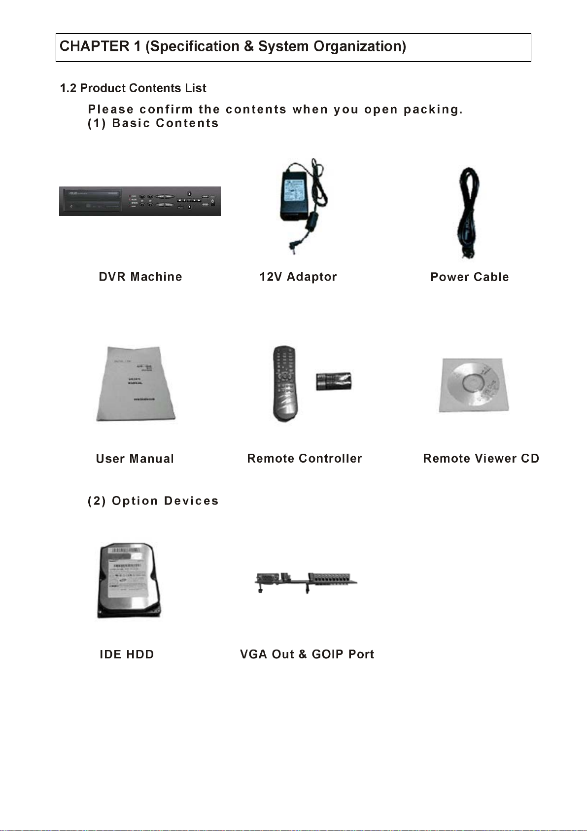
Please refer the bel o w mess age to confirm the modify contents.
1. PTZ CONTROL
★ ADD PRESET FUNCTION:FOR PELCO-D PROTOCOL
★ ADD SWING FUNCTION:FOR DONGYANG CAMERA (D-MAX)
2. CD-RW ( CD Read & Write Burner )
★ ADD CD-RW FUNCTION FOR DATA BACKUP
3. IE BROWSER
★ ADD IE BROWSER (ALLOW FOUR USERS MONITORING AT
AA ADSADSADSADSADTHE SAME TIME)
1
Page 3
‧INDEX
Front Panel
Rear Panel
Remote Controller
Hard Disk Installation
Camera Connection
Monitor Connection
Network Connection
Alarm / Relay / PTZ Connection
Power Connection
Hard Disk Format
System Power ON
Select Screen Mod e
Convert Screen Mode
Control PTZ / Focus
System Power OFF
2
Page 4
‧INDEX
Go to Search
Search by Da t e / Time
Search by Event
Go to Men u
Menu Initial
Display
Control Playing Viedo
Record
Camera
Size / Rec .Rate / Quality
Timer Recording Setup
Time Recording Weekly Se tup
Motion Detection Setup
Partial Motion Region Setup
Alarm Recording Setup
Status / Title Setup
Cover / PTZ Setup
Color Setup
Audio
Alarm
Audio Recording Setup
Live Audio Setup
3
Page 5
‧INDEX
System
Alarm Input Setup
Relay Output Setup
Date / Time
Network
Buzzer Setup
Password
Administrator Password
Manager Password
Operator Password
Disk Write Mode
System Information
Factory Default
Backup
System Requirement
DVR Remote Agent Installation
Monitoring
Function Introduction
Screen Division Selection
PTZ Control
Selection Network ID
AVI File Conversion
Color Adjustment
4
Page 6
‧INDEX
Client Sear ch
IP Setting
Function Introduction
Search Method
Search Option
Backup
Save Image
Log Search
Even t Search
Connection ID Setup
Option Settin g
Time Table
PTZ Protocol
PTZ Table
PTZ Control
PTZ Reset
Swing
Cross Cable Making Tip
5
Page 7
Hardware
OS
Video Input
Display Speed
Display Modes
Recording Speed
Monitor Output
Recording Resolution
Compression Method
Byte Size per Image
Recording Modes
Recording Schedule
Motion Detection
Audio Input / Output
Sensor / Alarm
VGA Output (Option)
PTZ Control & Port
Network
Internet viewers
Password
Back-up
Search Modes
Search Speeds
CPU
HDD
352 X 240
704 X 240
704 X 480
32 bit DSP
Unlimited HDD x 1 ~ 4
RTOS
4CH NTSC/PAL
120 (PAL : 100) fps
Full , Quad , Sequence
120 / 100
60 / 50
30 / 25
BNC / S-Video / 4 loop-out /1 Spot-out
NTSC : 352 X 240 , 704 X 240 , 704 X 480
PAL : 352 X 288 , 704 X 288 , 704 X 576
MPEG4 (Optimized)
3 ~ 5 Kbyte@352 X 240 (PAL : 352 X 288)
5 ~ 10 Kbyte@704 X 240 (PAL : 704 X 288)
6 ~ 16 Kbyte@704 X 480 (PAL : 704 X 576)
Continuous , Motion , Alarm
Schedule setting per camera
132 grids setting per camera
4 inputs / 1 output
4 inputs / 1 output
1 CH
RS-485
TCP/IP , I E , AP
Allow 4 viewers on the line at the same time
3 password level
LAN , CD-RW , Internet
By Time & Event
Up to 64 on both forward & backward
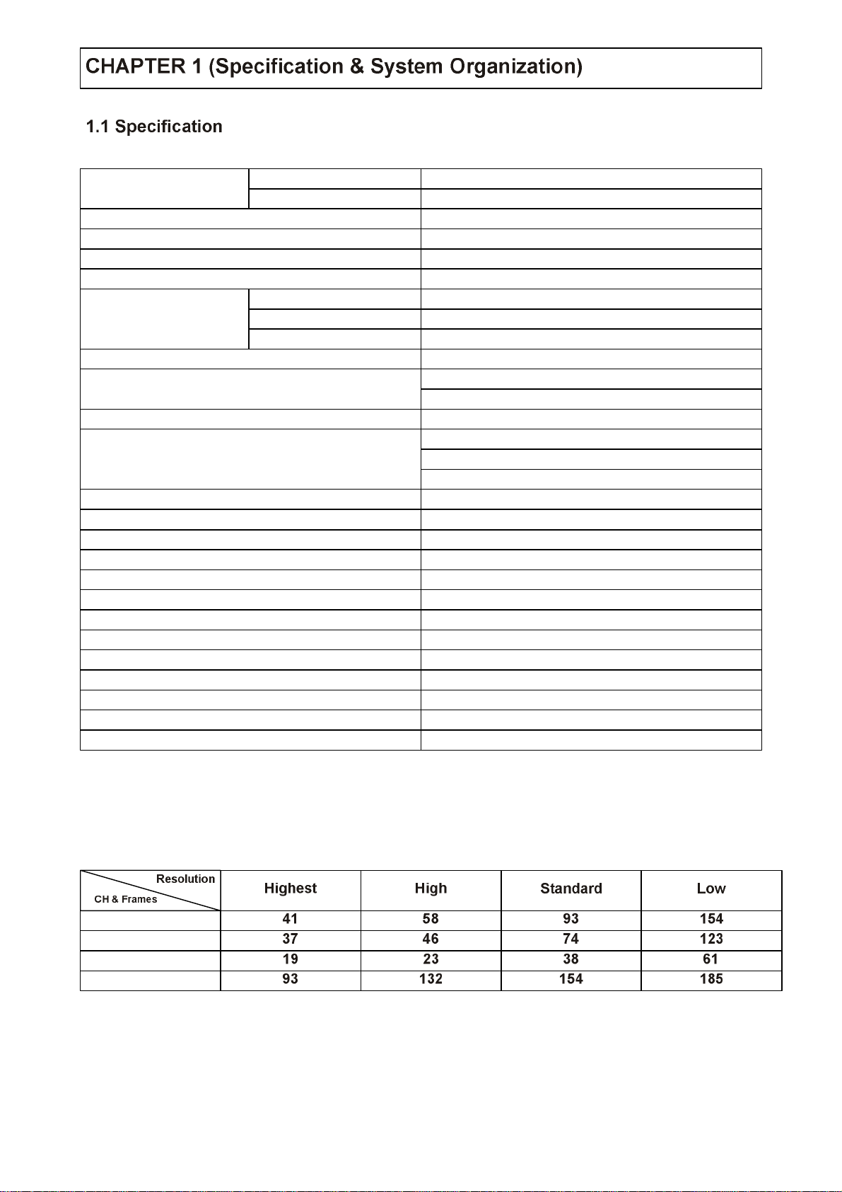
● 80G HDD Storage Capacity (hour)
4CH (CIF/30FPS)
4CH (2CIF/15FPS)
4CH (D1/7FPS)
4CH (D1/1FPS)
This Value is for continuous recording in bright place and large movement.
So it can be extend 2 ~ 3 times for ordinary environment.
6
Page 8
7
Page 9
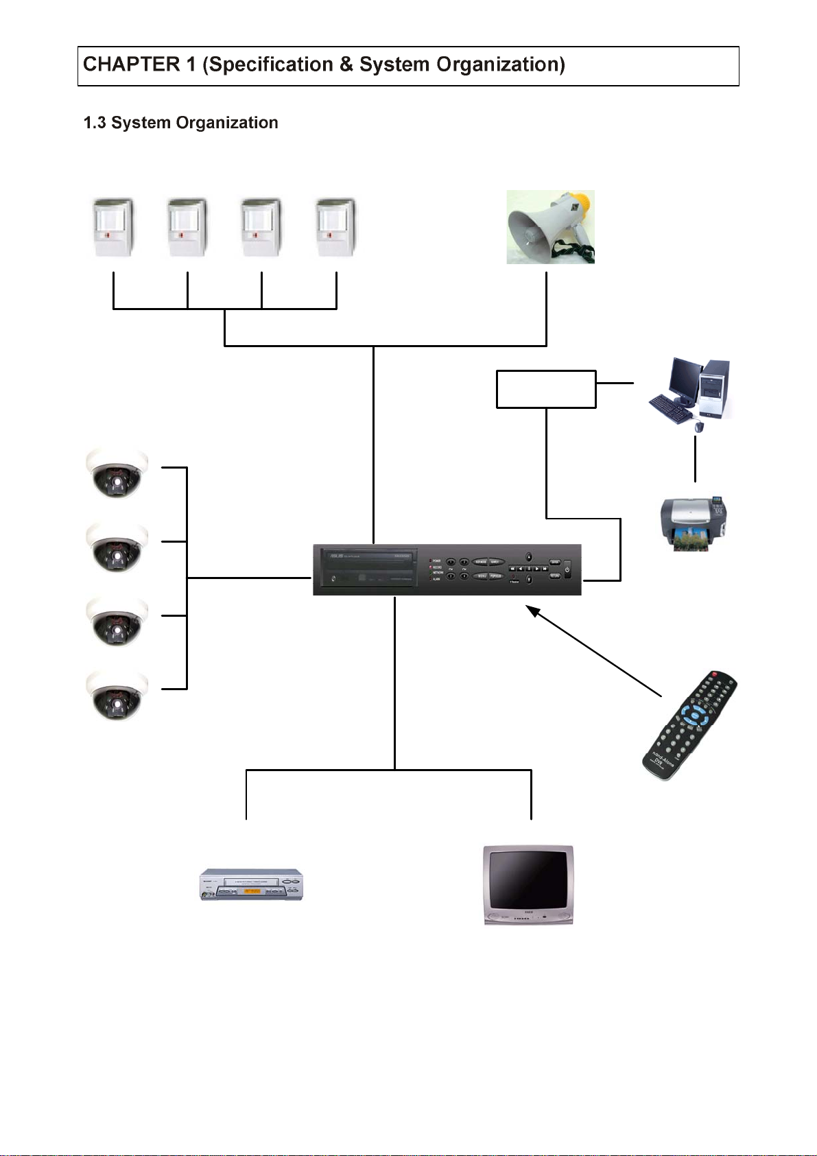
Alarm Sensor # 1 ~ 4
Relay Out
Client PC
Camera # 1 ~ 4
Alarm Input / Out
Video In
Network
TCP/IP
Video Out
VCR
Remote Controller
AV Monitor
8
Page 10
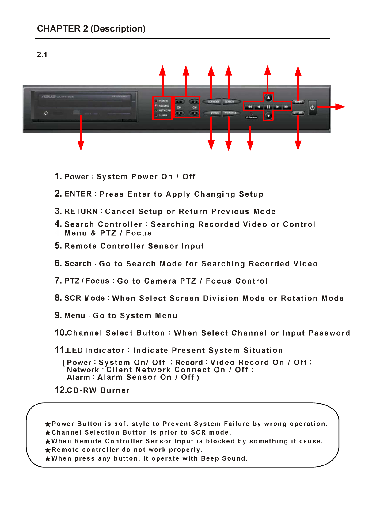
Front Panel
11 10 8 6 4 2
1
357912
Tip
9
Page 11
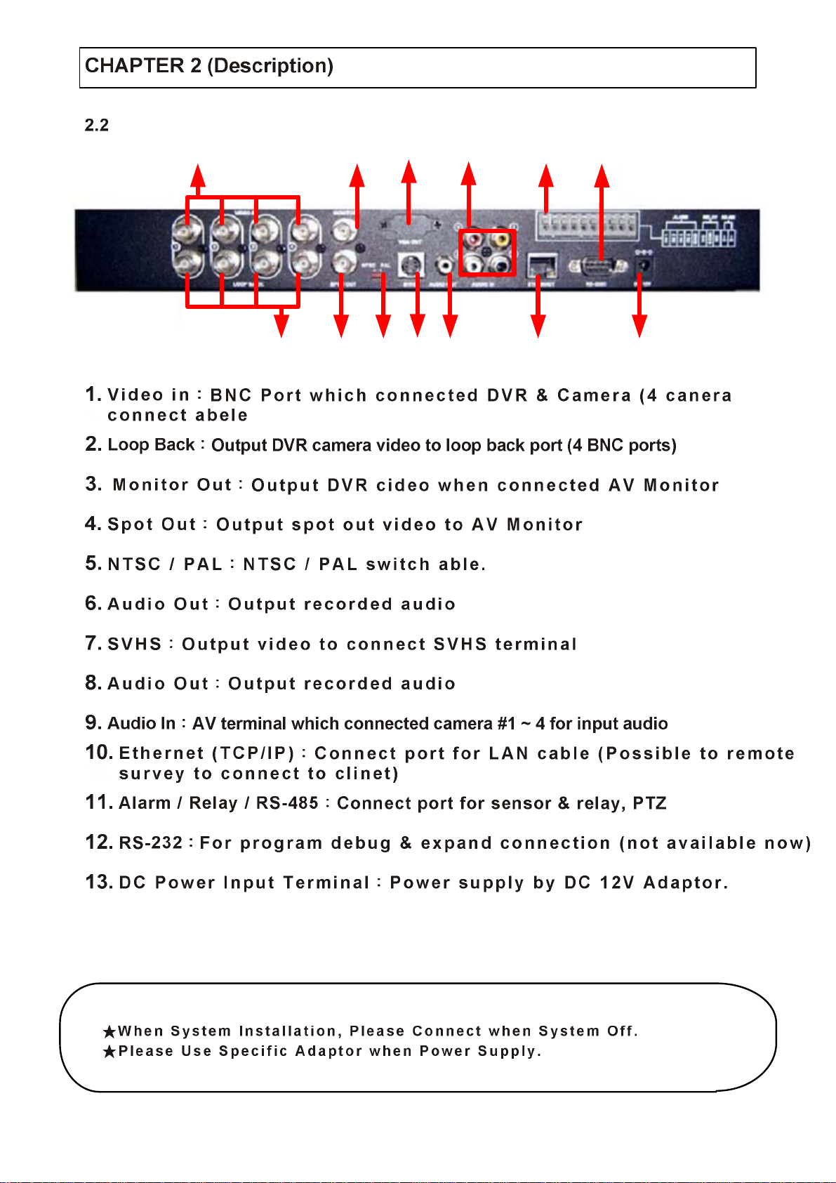
Rear Panel
13
6
912
11
42
57
108
13
Tip
10
Page 12
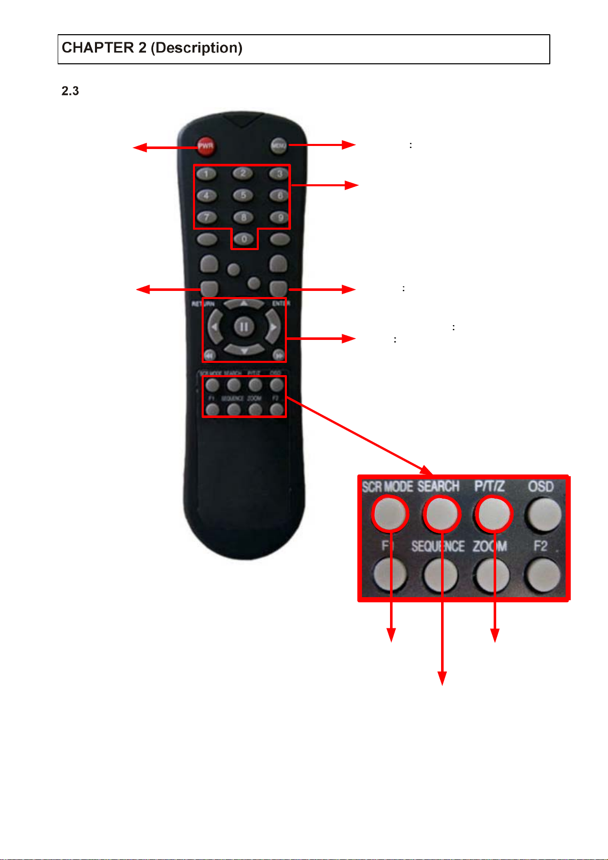
Remote Controlle r
POWER
System
ON/OFF
RETURN
Cancel
Setup to
Return to
Previous
MENU Open men u
Channel Select Button
(4ch Available , # 1~4
ENTER Apply Setup Change
Search Controlle r Control Playback Opti on
Speed of Playback, Move on Menu,
( EX
Control PTZ /Focus)
11
Change
Screen Mode
Sear ch Mod e
PTZ / IRI S
Mode
Open
Page 13
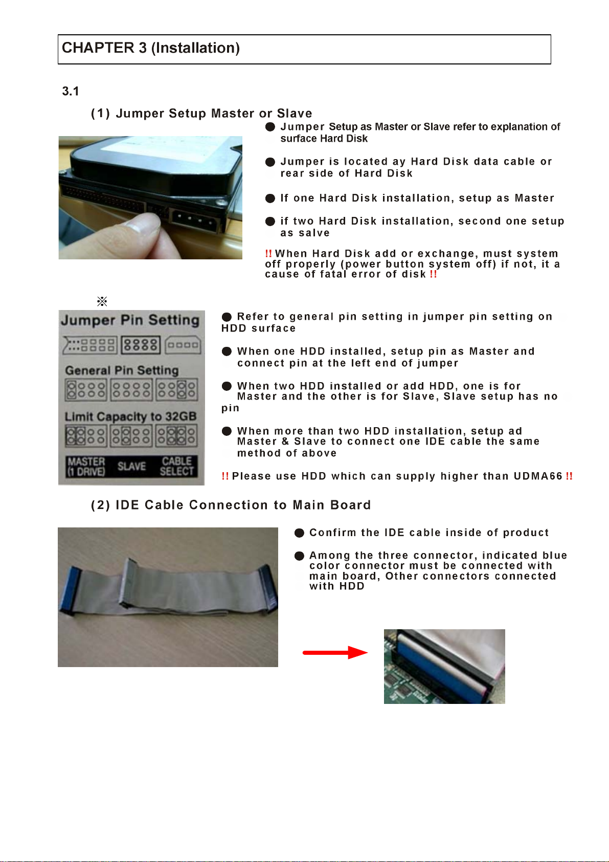
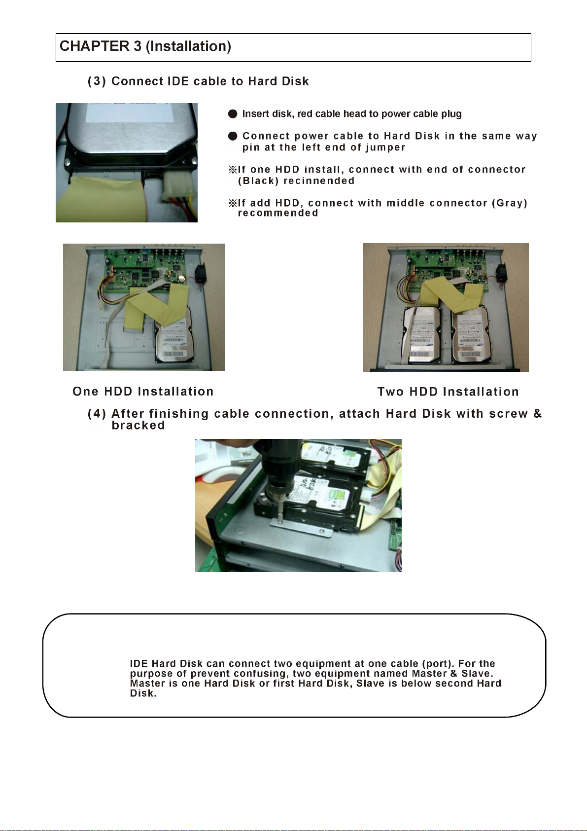
Hard Disk Installation
Example of Samsun g HDD Jumper Setup
12
Page 14
Tip
Master , Slave ??
13
Page 15
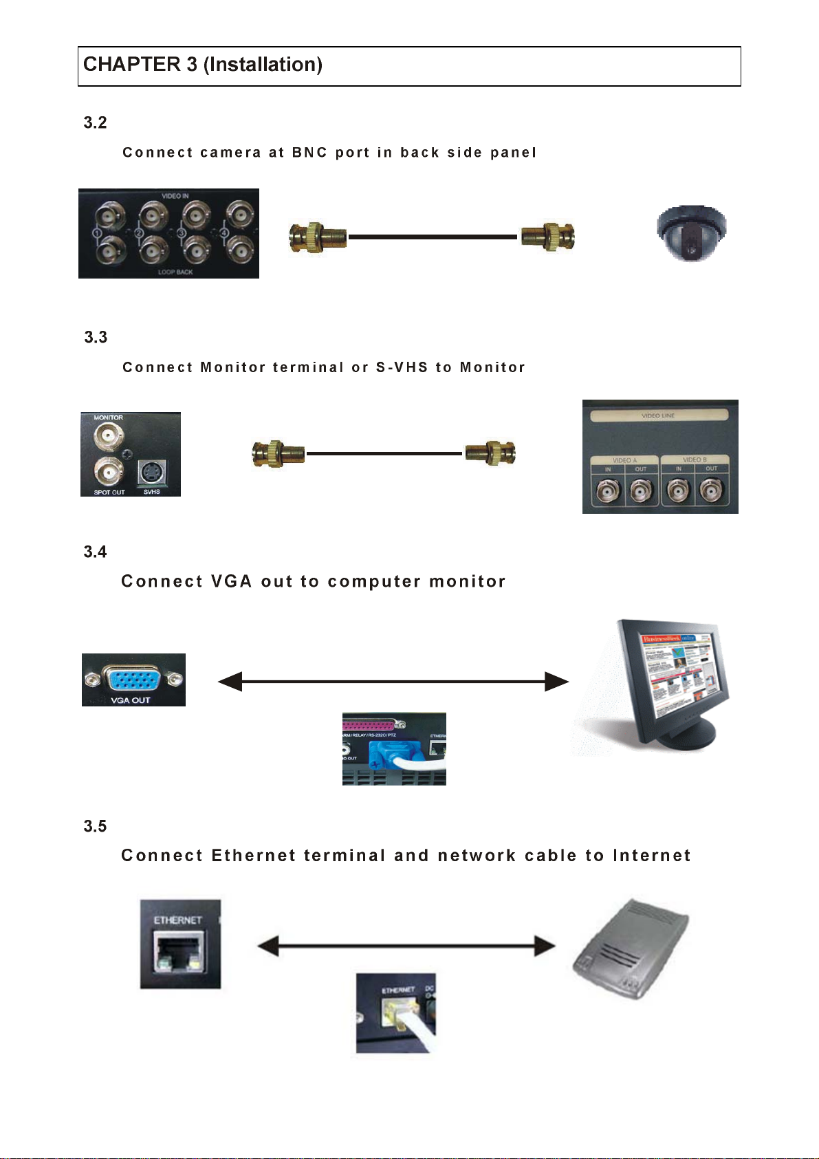
Camera Connection
Monitor Connection
Computer Conn ection
Network Connection
14
Page 16
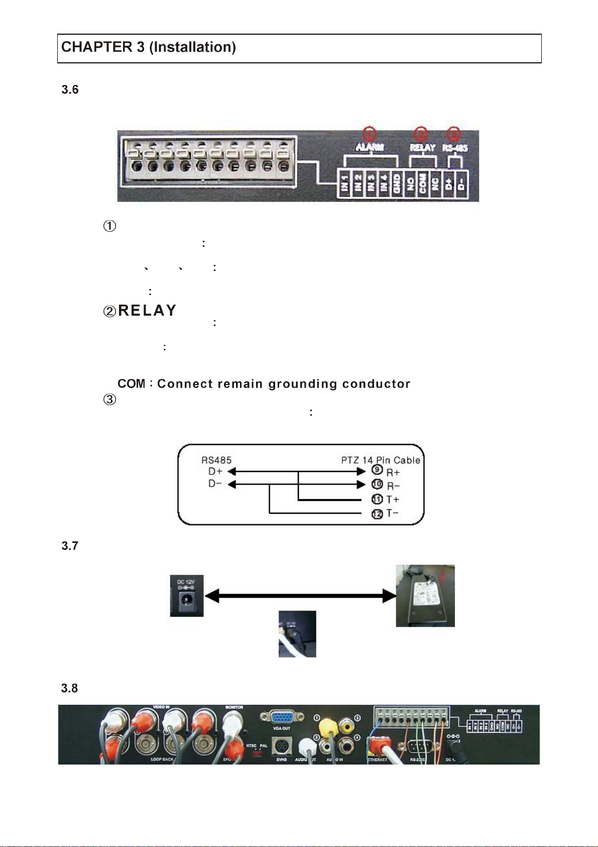
Alarm / Relay / PTZ Connection
ALARM
Alarm Input
1N1 1N2 1N3 conn ect sensor input by channe l
GND Connect to Ground system
Alarm Output
NO,NC After chec king Alarm output type ( Normal Open or
NO,NC Normal Close) and connect to No, NC
RS-485
Connect PTZ camera D+, D- Connect PTZ camera cont rol line
(+, - term inal)
Power Connection
Finishing Connection
15
Page 17
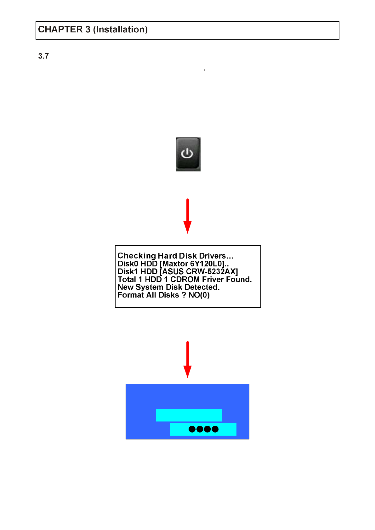
Hard Disk Format
If new Hard Disk not format, system can t detect the HDD.
So there is same situation of No HDD, please format HDD when insert new HDD
(Only Display possible, not work Menu & Search)
1.Power On
2.New HDD Format
(Select Play, Backward Play key
SETUP
User
Password
3.System Start
(Initial Mode)
Administrator
▲
▼
16
Page 18
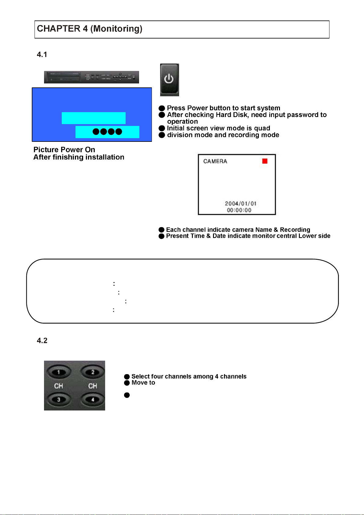
System Power ON
User
Password
SETUP
Administrator
▲
▼
Tip
Select Screen Mode
Check System Condition at LED
POWER
RECORD Showing Record On/Off
NETWORK
ALARM Lighti ng wh en Sensor Alarm A ctivat e
Showing System On/Off
Showing Cli ent Co nne ction Sta tus
quad enlargement watch mode when 4 screen
division mode
Move to quad enlargement watch mode whe n rotation mode
17
Page 19
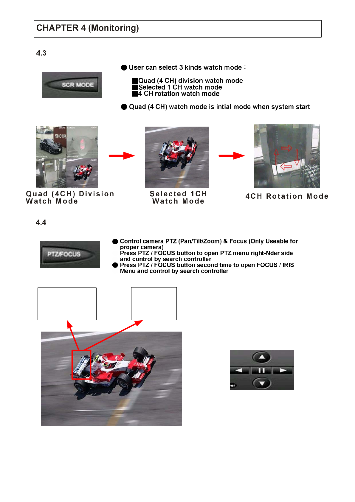
Convert Screen Mode
Control PTZ / Focus
FOCUS / IRIS CTL
UP
LEFT RIGHT
DOWN
PTZ CTL
UP
LEFT RIGHT
DOWN
FASTER
SLOWER
Search Controller
Control camera PTZ & FOCUS by search controller on PTZ Menu
18
Page 20

System Power OFF
SHUTDOWN
User
Password
Tip
Administrator
▲
▼
19
Page 21

Go to Search
Search
Search by Date / Time
Press search button and Log-
on Administrator or Manager
FASTER
Use direction key to move menu
SLOWER
To open each menu press enter
Retu rn to P r e v i u o s
●(Move to previous menu
●or exit search mode and
●return to eatch mode)
2005
Move cursor to selected date in calendar
(Recorded Date & Time indicated by gray color)
Press Enter to open selected date
Recorded Time appear to under side
Press Enter at selected time (One scale is 15 minutes)
Menu disappear and output recorded video
20
Page 22

2004.03.24
00:00:00
Control Playing Viedo
Showing recirded Date & Time at left-upper side as
● watch mode
● Showing playing condition at right-ubder side
Channel selection button in watch mode & SCR
Mode button are apply the same as search mode
(but Menu , Search and PTZ / FOCUS buttons are
Exceotion)
(normal speed (1x) forward playing
Search by Event
EVENT VIEW
Basic playing mode
Fast forward (2 ~ 64 speed) Fast backward (2 ~ 64 speed)
Payse video
Normal speed backward playing
Same function
Fast forward & Fast backward
Setup period to select start Date &
end Date for searchin g event
Searching power On / Off event
(Etc.) C on ce r ned sy st em event
21
Searching schedule change or
recording setup change event
Searching motion detected event
during the selected period
Searchin g ala rm ev ent dur i n g the
selected period
Showing at below output winodow
Page 23

EVENT VIEW
Tip
Date Indicate event occurrence order
Time Indicate event occurrence time
Event Indicate event conyends & cam No.
Event searching method
User can search event by direction key
Search event to please enter at selected
※ event from event occurrence time
Control video is the way as time mode
※ control
22
Page 24

Go to Menu
User
Password
Tip
Menu Initial
SETUP
Administrator
▲
▼
Press menu button on front panel in watch mode
Ask password
Input password using by channel select
[1] [2] [3] [4]
After input password press Enter to see
menu
MENU
Every system setup can change or maintain
at Menu (6 Setup)
Move to Menu by using up & down
button
To open detail Menu or to
apply input
Return to previous Menu or Return to
Return watch mode
23
Page 25

Display
MENU
1. Date / Time Date & Time mark On / Off
2. Title
3. Statu s
4. Bord er
5. Bord er Color
6. Sequ ence Dwell
mode at Display
7. Spot-out Dwell
8. Deinterlace M ode
8. applying when D1 (708 x 480)
Camera name On / Off
Record condition mark On / Off (Recording Red, Pre-recording green)
Border mark On / Off, when 4 CH division watch mode
Select border color (White, Blue, Red, yellow, Green, Gray)
Setup rotation mode at display (1 ~ 60 sec) when 4 CH rotation 6.
Setu p spot-out time cycle (1 ~ 60 sec) to transmit video
Remove screen spread on High resolution, Low Frame only
Record
MENU
24
Page 26

Size / Rec .Rate / Quality
Size /Rec. Rate / Quality Setup Recording Resolution, Compression Rate, Quality
Size 352 X 240 702 X 240 702 X 480
Rec. Rate ossible to selec t 1 ~ 30
Quality 4 Levels (High, Highest, Low,
Quality Standard)
Tip
NTSC 3 52 X 240(120fps) 702 X 240(60fps) 702 X 480(30fps)
PAL 352 X 228(100fp s) 702 X 228(50fps) 702 X 576(25fps)
Timer Recording Setup
Camera Indicate camera No. to setup
Record Record On / Off
Mode Record Mode (Daily or Weekly)
Start Setup recording start time (0 ~ 24 hr)
Stop Setup recording end time (0 ~ 24 hr)
Recording time is between start time and end time
Motion Motion detection recording On / Off
(Record setup must be On, when motion detection recording)
25
Page 27

Time Recording Weekly Setup
Weekly Mode Setup
0 1 2 3 4 5 6 7 8 9 10 11
12 13 14 15 16 17 18 19 20 21 22 23
SUN
Mon
Tue
Wed
Thu
Fri
Sat
SUN
Mon
Tue
Wed
Thu
Fri
Sat
0 1 2 3 4 5 6 7 8 9 10 11
12 13 14 15 16 17 18 19 20 21 22 23
Scheduled Region Indicted Yellow
0 1 2 3 4 5 6 7 8 9 10 11
12 13 14 15 16 17 18 19 20 21 22 23
SUN
Mon
Tue
Wed
Thu
Fri
Sat
After deselect schedule, activated region
by press Enter and select Date & Time to
move cursor
After selecting region and press Enter
again to finish schedule setup
26
Page 28

0 1 2 3 4 5 6 7 8 9 10 11
12 13 14 15 16 17 18 19 20 21 22 23
0 1 2 3 4 5 6 7 8 9 10 11
12 13 14 15 16 17 18 19 20 21 22 23
SUN
Mon
Tue
Wed
Thu
Fri
Sat
Setup Date & Time schedule in the
same way after finishing schedule
setup, Press Return for Save & Exit
Motion Detection Setup
SUN
Mon
Tue
Select All
Deselect All
Save & Exit
Wed
Save & Exit
Cancel
Thu
Fri
Sat
● Select All:Entire region select
● Deselect All:Cancel region
● Save & Exit:Save changing setup & exit
● Cancel:Cancel changing setup & exit
Camera Indicate camera No. to setup
Sensitivity Control sensitivity (1 ~100), Large No. is more sensitivity
Region Setup motion detect range
Entirely setup entire screen
Partially setup partial screen
When choose region as partially, Move to partial range setup, Press Enter
after range setup to finish region setup
Pre-Motion Duration Setup Pre-Motion (1~5 Sec)
Recordinf time after motion dete cted (5 sec~3 min)
27
Page 29

Partial Motion Region Setup
None-Activage move cursor (red)
None Active region (Yellow)
Active partial setup cursor (blue) Partial setup finish cursor (limpid)
(1) (2) (3)
Default is none active
region, color is yellow
Move cursor by direction key
and press Enter at selected
region, color is bule
(4) (5) (6)
Press Enter again to see
partial setup finish cursor,
color is limpid
Move cursor by direction key
and press Enter at selected
region, color is bule
(7)
Select All
Deselect All
Save & Exit
Save & Exit
Cancel
Same method as (4)、(5)
possible to expand none
activated region
Select All Select entire region
Deselect All Cancel region setup
Save & Exit Save the change setup and exit
Cancel Cancel change setup & exit
Same me t hod as (4 ) 、(5)
possible to reduce none
activate d re gi o n
28
Page 30

Alarm Recording Setup
Camera Indicate camera No. to setup
Record Setup record On / Off when alarm activated
Start Se t up alarm recording start time (0 ~ 24 hr)
Stop Setup alarm recording finish time (0 ~ 24)
Pre-Alarm Duration When alarm recording, Setup start recording time
befor e ala rm activate (1 ~ 5 sec )
Post-Alarm Duration Setup alarm recording time after alarm activate
(5 sec ~ 3 min )
Tip
Camera
Motion setup work by time schedule and alarm schedule work independently
MENU
29
Page 31

Status / Title Setup
Camera Indicate camera No. to setup
Status Indicate camera status (Connected / Disconnected)
Title Setup camera name to show left upper side
Tip
Title input method
Using direction key, Up & Down keys for alphabet A ~ Z
Cover / PTZ Setup
Camera Indicate camera No. to setup
Covert Setup covert On / Off
What covert? When covert on watch mode. Display video is hodden, but recording is on.
Address Select PTZ camera address
PTZ Protocol Select kind of PTZ camera
Baud Rate Setup PTZ communication speed (2400, 4800, 9600 BPS)
PTZ supplied protocol Samsung(MRX-1000) Honeywell(GC/GMC 7552 Zoom)
Kalatel(KTB312) Panasonic(W-V-CS850 WV-CSR604) Pelco-D Pelco-P
30
Page 32

Color Setup
Camera Indicate camera No. to setup
Bright Control monitor bright
Contrast Cont rol monitor contrast
Color Control monitor color
Tint Control monitor tint
All setup possible to control 0 ~ 100
Audio
MENU
Audio Recording Setup
● Camera Indicate ca mera No. to setup
Audio Rec. Setup recording On / Off from external audio in terminal
Audio Ch. Setup audio in terminal channel & audio output camera
31
Page 33

Tip
User can listen saved audio with saved video
Audio check in search is possible only normal speed (1x)
Forward playing at 1 CH mode (audio recorded channel)
Live Audio Setup
Live Audio Audio output On / Off, Live audio output from audio in treminal
Monitoring ch. Select channel for audio output Nr. 1 ~ 4 audio in
Network Audio Select One-way or Two-way (not release)
Alarm
Alarm Input Setup
MENU
32
Page 34

Alarm Indicate alarm input terminal No.
Status Setup alarm sensor connection status (Connected / Disconnected)
Camera Input camera No. 1 ~ 4 connect alarm
Type Setup alarm sensor N/Open, N/Close type
說明
Alarm Indicate alarm input terminal No.
Relay out Setup relay connect with alarm sensor
Mode Setup reacted relay time (5 sec ~ 5 min or until key-in)
Relay Type Setup relay type N/O or N/C
Generally alarm sensor can be divided two types
Normal open type is open sensor electrically and reacted when signal is
connected
Normal close type is close sensor electrically and reacted when signal is
disconnected
Relay Output Setup
Tip
System
Latched / Transparent
Latched when sensor alarm activated. Relay reacted in setup duration
transparent re lay reacted tempor ary during sensor. Alarm activate.
MENU
33
Page 35

Date / Time
Date Se tup pres ent da te (y yy y-mm-dd)
(If time setup to pass date, Ask delete data for the past date,
No -> Date / Time no change, Yes -> after deleted past data and change Date / Time
Date Format Selec t date output type (ex 2005-06-15 or 2005/06/15)
Time Setup present time
Time Format Setup time type as 12 hour base or 24 hour base
Daylight Saving Summer time applying status
Network
DHCP On -> Indicate IP address for DVR automatically,
Off -> User input IP address by self
DDNS On -> Connect the DVR by the fixed domain name,
Off -> Connect the DVR by IP address
WEB Server On / Off
Network Speed Setup network seed (network speed from system. Depend on network
status)
If change network setup, New change apply when after rebooting.
34
Page 36

DHCP ON、DDNS OFF
DHCP ON、DDNS ON
DHCP OFF、DDNS OFF
DHCP OFF、DDNS ON
If your network connect at router, please must work the port forwarding .
Otherwise you can t receive the service well.
When you connect by the web, please 80 port must be work port forw arding for DVR.
When you connect by the Remote Agent program, please 6100 port (User can change it) must
be work po r t forwarding for DVR .
If you want to know more, please ask to the network manager or refer the router manual.
DHCP
1. Enter 6.System 6.2 Network on the Menu.
2. Setup DHCP On / Off
3. DHCP Off
4. DHCP On
5.Can see the setup IP automatically ay the system information.
DHCP(Dynamic Host Configu rat io n Protocol) Indica te IP addre ss fo r t he DVR automatically.
User input IP address by himself.
After DHCP On, reboot the system.
35
Page 37

DDNS
DDNS(Dynamic DNS) You can connect the DVR by the fixed domain name.
00115f000001.dvrlink.net) at client or Web without entering at IP address
(Ex
1. Enter to
2. Setup DHCP On or Enter the IP address.
3. Setup DDNS On and reboot.
4. Enter to
5. Confirm the MAC address.
6. The domain name is “ MAC address.dvrlin k.n et ”
If MAC address is 00-11-5f-0 0- b5-a7, the domain name is “ 00115f00b5a7.dvrlink.net “
(Ex
7. If you connect by 00115f00b5a7.dvrlink.net at client program or Web, yo u can co nn ect the DVR.
If you don
If you use the DDNS, there is no necessity to ent er agai n the I P address every connection.
6.System 6.2 Net work’ on t he menu.
6.System 6.6 System info rmat ion’ on the menu.
If your network connect at the router, please must port forwarding.
Please you must enter the exact IP address, DNS Serve r, Gateway, Subnet Mask.
Please you must connect the DVR at external network.
t follow 1,2,3 you can t receive the DDNS service.
Confirm IP and MAC Address
1. Possible to confirm IP address for the DVR at the System Information.
2. Fixed MAC address of the DVR
36
Page 38

Buzzer Setup
Password
Alarm Input Alarm On / Off, when alarm activate.
Video Lo s s Alarm On / Off, when camera disconnected.
Key Input S et up key input sound.
Administrator Password
Current Password Input current password ( Initial password is 1234 ).
New Password Input new password.
Re-enter the Password Re-confirm new password.
Save & Exit Applying new password .
37
Page 39

Manager Password
Current Password Input current password ( Initial password is 1234 ).
New Password Inp ut new passw ord .
Re-enter the Password Re-confirm new password.
Save & Exit Applying new pa s sword.
Operator Password
Current Password Input current password ( Initial password is 1234 ).
New Password Inp ut new passw ord .
Re-enter the Password Re-confirm new password.
Save & Exit Applying new pa s sword.
Disk Write Mode
Disk Overwrite Select overwrit e permi ssion, when hard disk is full.
ON Overwrite ha r d disk from oldest data.
OFF Whe n hard disk full, stop recording and BUZZER activa te ( refer t o menu 6.3 buz z er set up ).
Disk initialize Now Refreshmen t Har d Disk all recorded data deleted.
When select disk initialize alarm message showi ng select YES to sta rt disk initialize .
When change disk overwrite ON / OFF mode, the change will be applied from change time. For example
When overwrite on mode & Disk full, change to overwrite off mode and then it will be applied new fill HDD
full after change time.
38
Page 40

System Information
S/W Version Indicate software version of the product.
H/W Version Indicate hardware version of the product.
Video Signal Type Indicate video signal typ e.
Disk Size Indicate hard disk capacity.
Number of HDD Indicate present installed HDD number.
IP Addres s Display ethernet card IP address.
MAC Address Di spl ay ethernet card MAC address.
Factory Default
Press Enter to start initialize.
Showin g wa r m ing messa g e and pr es s OK t o ru n in it i a lize.
If do factory default, every setup is initialized, but savi ng image is erased.
39
Page 41

Backup
MENU
1
2
CD-RW Proceed
1. CD-RW Burner display
2. Fill the start time in
3. Fill th e end time in
4. Channel selection
9
3
4
5
6
78
5. Video backup selection
6. Audio back selection
7. Event backup selection
8. Title backup slelct io n
9. Start key
Note Move to icon start and press Enter to CD burning after all set.
40
Page 42

System Requirement
1. Main Board (CPU) Celeron 500-700(Minimum) P ent ium-4 recommend.
2. OS
3. Memory (RAM)
4. VGA:Overlay Yv12 format graph ic card
All Radeon, Nvidia (Above Geforce), Matrox (Above G400) compatible video card, above DIVX
codec 5.1 (When use Media Player)
ore than Windows 98 DirectX 7.0A
More than 128M
DVR Remote Agent Installation
Step 1 Open CD and run DVRRemoteAgentSetup. exe
Step 2 Close all running software an d pres s Next
41
Page 43

Step 3 Ask designate folder to install DVR Remote Agent recommen d basic set up
c:\program Files \DV R Remote Agent and click Next.
Step 4
Showing process of copy files.
42
Page 44

Step 5 Appear DirectX 7.0a install menu. If DirectX versio n lower than 7.0a, press Yes to start
install.
Step 6
When finishing installation, System must be restart. Click <YES>.
Step 7 Finish DVR Remote Agent program installation.
43
Page 45

Monitoring
Function Introduction
3
CAMERA1
352x240
CAMERA2
352x240
1
4
5
6
2005-5-10 09:28:46
CAMERA3
2005-5-10 09:28:46 2005-5-10 09:28:46
352x240 352x240
2005-5-10 09:28:46
CAMERA4
2
1. Main screen image showing present surveillance camera image.
2. Camera selection button
3. Hide / Exit
4. Time Output
5. Search
5. Setup
6. I/D Selection
7. Connect
8. Screen Division Selectio n
9. Save by AVI File
10. Color Adjustment
11. PTZ Co ntrol Button
12. Exit
Hide D VR client windows or ex it pr og r a m .
Showing present Time & Date.
Move to search mode to play video.
Move to setup to chan ge network setup or option.
Select I/D connect server.
Connect server(DVR). Disconnect Disconnect from server.
Transmission live imag e save by AVI file.
Exit DVR client.
Indicate connected camera No. & select image to click camera No.
Change screen division mode.
Adjust color of live tran smission image.
Control camera PTZ & Focus.
7
8
9
10
11
12
44
Page 46

Screen Division Select
1x1 View Showing one (1) vid eo wh ich user selected
(Selection video by camera selection button)
4X4 View Quad screen division mode.
Scenario View One large screen mode showing one
by one (1x1 view) depend on User selection time
(not work s c r e en divis ion mode).
Full Screen View Present video move to full screen
mode m ou s e do uble clic k wh en re turn previ ous.
PTZ Control
P/T/Z C ontroller Camera P/T/Z contro l by dire ct io n keys.
Focus/Zoom Selection Button Focus or Zoom control
by button.
Selection Network ID
Select I/D to connect server
I/D can be added. Changed and deleted at set up .
Control Button Focus or Zoom control.
Network Information Icon
Click network informatio n icon t o see a
popup window for connected server I/D IP,
And port information.
45
Page 47

AVI File Conversion
Click AVI conversion button to start AVI file conversion.
During AVI conversion showi ng mess age and before click
stop to save AVI file continuously.
Press stop to open designate file name & saving location
and save AVI file.
Saved AVI file can open ordinary moving picture player.
Moving picture player codec version is above Divx 5.1.
Color Adjustment
Click controller possible to control color.
Change brightness, contrast, saturation from 0 to 100.
Click OK to finish changing set up .
46
Page 48

Client Search
Function Introduction
1
CAMERA1
352x240
CAMERA2
352x240
3
4
2005-5-10 09:2 8:46 2005 -5-10 09 :28:46
CAMERA3
352x240 352x240
CAMERA4
5
6
7
2005-5-10 09:2 8:46 2005-5-10 09:2 8:46
8
2
1. Search screen playing select ed vi deo.
2. Search Bar
3. Live
4. Screen Division Selection
5. Search Option
6. Camera S e lection Button
7. Quick Search
8. Search Controller
Return to display mode. Setup Open setup to change network se tup or opti on
Search & Indicate camera reco rdi ng situation by time bar.
Change pla ying screen divis ion mode.
Backup video or search event.
Select camera at the 1x1 view.
Find image to designated Date & Time.
Cont ro l pl a yi ng video.
47
Page 49

Search Method
1
5
23 4
1. Indicate 0 ~ 24 hour.
2. Indicate recording situ at ion (Blue
3. Search Bar
4. Indicate camera channel to confirm camera recording situation.
5. Refreshment recording inf ormation situation window by camera cha nn el
6. If connected channel is 5 or more, anoth er chan nel will be scroll
Select video to drag mouse search controller recorded area
No record. Yellow Recorded image at the time)
6
Search bar will move
if input D ay & Ti m e
Program Exit
Click Bay setup and
select day on calendar
Play video as normal speed (1x)
Stop play vi de o
48
Page 50

Search Option
Save Image
Backup
Backup play
Backup
Backup image from server to remote PC
Log Searc h
Event viewer
Print image
Backup Time Designate backup time
(Now or Later)
Designate backup Date & Time when now or
later
Source
Designate backup image dat a leng t h to inpu t start
time & end time
Channel Check camera channel for backup
Select All Deselect All
Press OK to open backup status & start backup
When finish backup. Back status windo ws disappear & backup data save at hard disk
root folder in remote PC.
49
Page 51

Backup Play (DVR Player) Transfer to DVR Player
1
2
34
5
1. Showing image (possible to only 1x1 view mode)
2. Backup file open to play first video
ch02_0501310730_0501311735.rec
Ex
(Backup file for #Ch2
3. Indicate present playing video camera channel No.
4. Indicate present Time & Date and possib le to search Time & Date
5. Search controller, the same way of previous search
Jan 31 07H30M ~ 17H35M)
Tip
Backup play setup in searc h mode is the same as DVR player, so it can be run
independentl y without ru nning remo te program.
50
Page 52

Save Image
Save image at hard disk or remote dis k
Click save image icon during playing video
Designate file name, file type (JP G, GMP), an d locat io n an d press Saving
Conversion and saving image from remote viewer
Print image present ima ge cap tu re and print out image
During play video, click print image.
After selecting printer, start image printing.
Print out remote viewer image.
51
Page 53
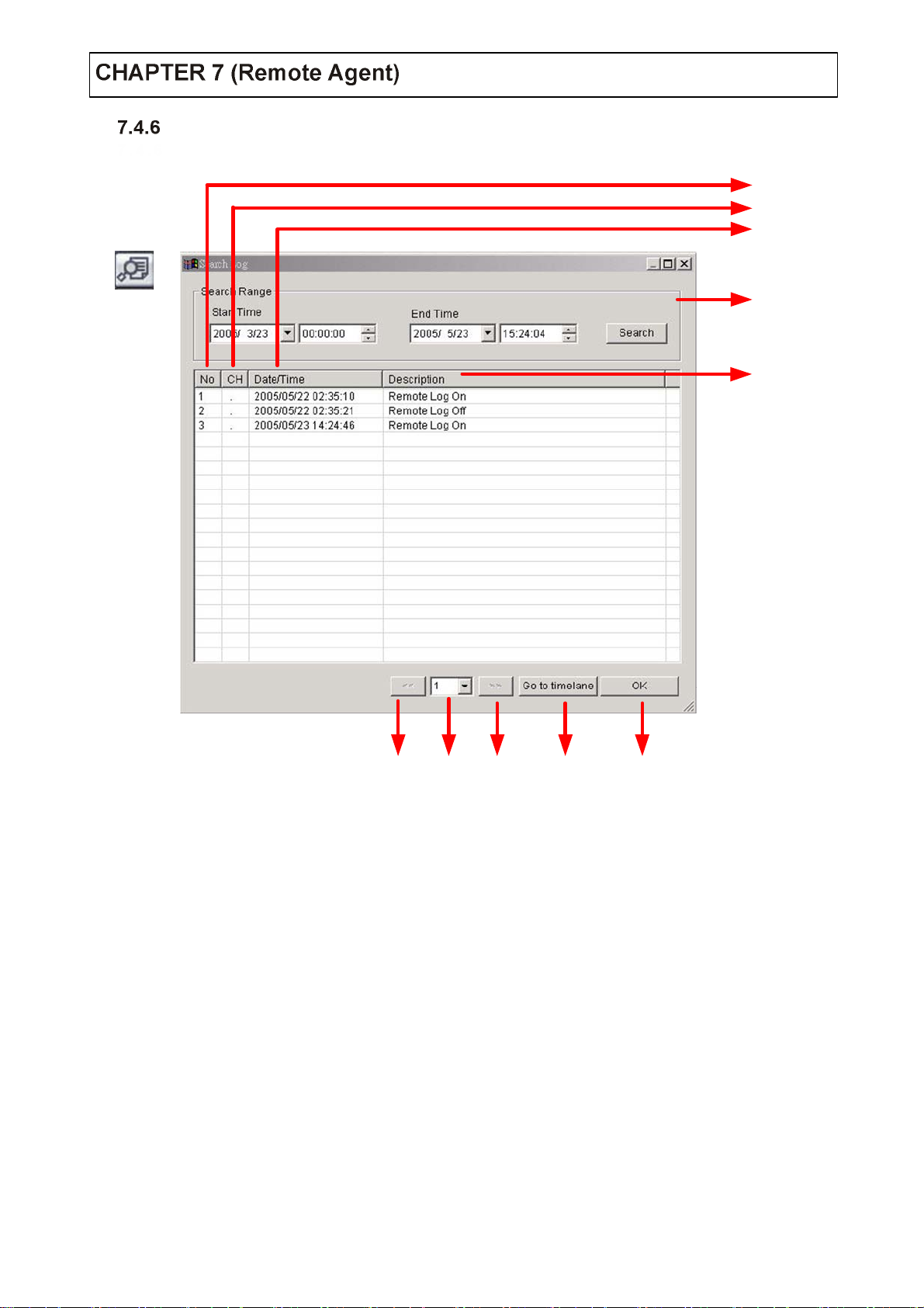
Log Search
Find video centering around event log at server
2
3
4
1
5
678910
1. Input start time and end time at the selected date to search event.
2. Indicate event log order No. (Max event log No. 1 page is 100).
3. Indicate event occurred camera No.
4. Indicate event occurred Time & Date.
5. Indicate Event detail description..
6. Move to previous page.
7. Select page number.
8. Move to user select page
9. After select event, move sear ch ba r in sear ch mod e.
10. Return to search main to play event image.
52
Page 54

Event Search
Showing present even t in server & find image
3
1
4
2
1. Indicate event occurred order No.
2. Indicate event occur red camera No.
3. Indicate event occur red Time & Date.
4. Indicate event detail description.
5. After select event, move search bar in search mode.
6. Return to search main to play selected event image.
56
53
Page 55

IP Setting
Conne ction ID Setup
2
3
1
4
5
6
10
9
8
7
1. ID Status Indicate present saving ID & ID information.
2. Input name to add or amend ID.
3. Input IP address to add or amend server.
4. Indicate port No.
5. Input ID for connecting server.
6. Input password for connecting server.
7. Click t o input new ID information.
8. After input all ID information, add ID information at ID status.
9. After amend all ID information, applying change ID information.
10. Selected ID delete at ID status.
Tip
Initial ID & Password is Administrator & 1234
54
Page 56

Option Setting
2 3
1
1. Control screen rotat io n time scenario mode at watch mode
1. (Possible to setu p from 1 ~ 300 sec.)
2. Possible to select event kind plurally from server, remote client only can see
2. selected event (System, HDD, alarm, video, REC).
3. Setup print-out image of informatio n display from serv er
3. (Name, Date, Resol ution).
4. Designate backup image saving folder remote PC.
4
55
Page 57
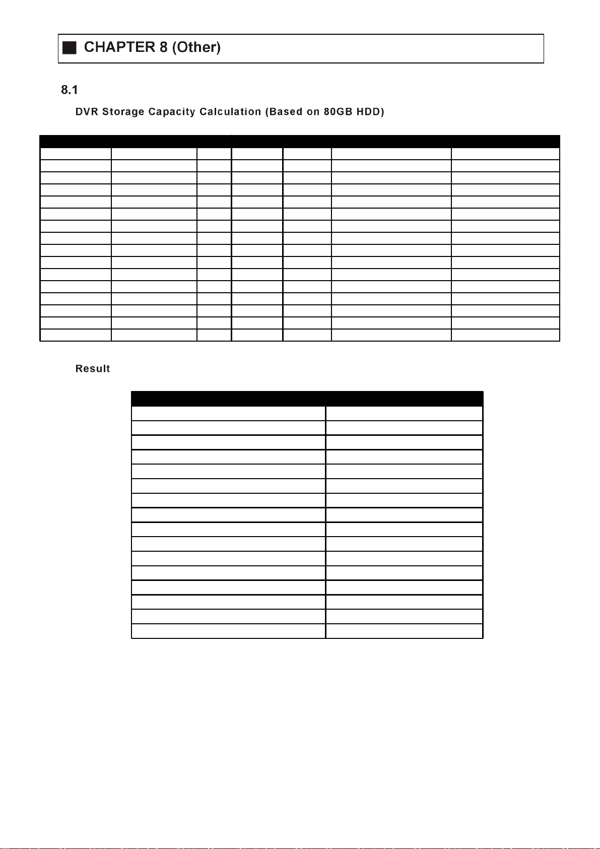
Time Table
Resolution Image Size (KB) FPS Second Minute Record Hours Per Day Number of Cameras
352x240 (CIF) 3.5 (Highest) 30 60 60 24 4
352x240 (CIF) 2.6 (High) 30 60 60 24 4
352x240 (CIF) 1.6 (Standard) 30 60 60 24 4
352x240 (CIF) 1.1 (Low) 30 60 60 24 4
704x240 (2CIF) 8.5 (Highest) 15 60 60 24 4
704x240 (2CIF) 6.8 (High) 15 60 60 24 4
704x240 (2CIF) 4.3 (Standard) 15 60 60 24 4
704x240 (2CIF) 2.7 (Low) 15 60 60 24 4
704x480 (D1) 37 (Highest) 7 60 60 24 4
704x480 (D1) 30 (High) 7 60 60 24 4
704x480 (D1) 19 (Standard) 7 60 60 24 4
704x480 (D1) 12.5 (Low) 7 60 60 24 4
704x480 (D1) 52 (Highest) 1 60 60 24 4
704x480 (D1) 37 (High) 1 60 60 24 4
704x480 (D1) 32 (Standard) 1 60 60 24 4
704x480 (D1) 27 (Low) 1 60 60 24 4
Required Storage Capacity (GB) Time to HDD Full (About)
36.2 80/36.2 = 2.2 Days
26.9 80/26.9 = 2.9 Days
16.5 80/16.5 = 4.8 Days
11.4 80/11.4 = 7 Days
44 80/44 = 1.8 Days
35.2 80/35.2 = 2.2 Days
22.2 80/22.2 = 3.6 Days
13.9 80/13.9 = 5.7 Days
89.5 80/89.5 = 0.8 Days
72.5 80/72.5 = 1.1 Days
45.9 80/45.9 = 1.7 Days
39.2 80/30.2 = 2.6 Days
17.9 80/17.9 = 4.4 Days
12.7 80/12.7 = 6.2 Days
11 80/11 = 7.2 Days
9.3 80/9.3 = 8.6 Days
56
Page 58

PTZ Protocol
PTZ Table
8.2.1 Present DVR Supply Only PTZ/FOCUS/IPIS Function
8.2.1 (Planning other features)
MAKER MODEL
PTZ Control
FASTER
BACKWARD
Press PTZ/FOCU S button to op en PTZ men u at right- un de r si de an d
control by search controller.
When press PTZ/FOCUS button by turns, FOCU S/IRIS preset, swing menu
will appear at the right - und er side and possible to control by search
controller.
FASTER
BACKWARD
FORWARD
FASTER
FORWARD
SLOWER
Search Controller
57
Page 59

UP
LEFT RIGHT
DOWN
PTZ CTL
UP
LEFT RIGHT
DOWN
PTZ Control
1. Control camera movement by “FASTER” “SLOWER “BACKWARD PLAY “PLAY
1. button, (Up-Down-Left-Right).
2. Zoom in & out by button “FAST BACKWARD”.
3. Keep press button make continuous movement.
FOCUS/IRIS Control
1. Control IRIS “FASTER”, “SLO WER” button .
2. Focus On by “BACKWARD OKAY”, “PLAY” button.
3. Zoom In & Out by “FAST BACKWARD”, button “FAST FORWARD”.
4. Keep press button to make contin uo us move nen t .
58
Page 60

PTZ Reset
Swing
Cross Cable Making Tip
1. By pres e t function, possible to setup d ir e ction and Focus of
1. PTZ camera.
2. After selecting position at PTZ control mode, save data at
2. preset mode.
3. Setup number from 1 ~ 123 by FASTER & SLOWER button ,
4. Save by front panel key No.1 button or F1 butto n on remot e
4. controller.
5. To move to saved location, press fro nt pan el key but t on No.2
5. or F2 on the rem ot e ci nt r o ller.
1. Swing function dedicate each No. of saved preset and swing
1. as pan or tilt.
2. Changing mode by “BACKWARD” and “PLAY” button.
2. Changing setup by “FASTER” and “SLOWER” button.
3. Pan swing mode
3. Tilt Swing mode Rotat e up, do wn side.
3. Start preset
3. End preset Select end point (1 ~ 123).
3. Swing time
3. Swing speed
4. Save by front panel key No.1 button or F1 butto n on remot e
4. controller.
5. For start swing mode, press front pan el key No.2 or F2
5. button on remote controll e r .
Rotate left, right side.
Select startin g point (1 ~ 123).
Select half time as each p oi nt (1 ~ 64 sec).
select moving speed on camera (1 ~ 64).
59
Page 61

Connec tion Method
1. Conne c t LAN Cable part-A and LAN plug by orde r a s one to one.
2. Connect to LAN cable part-B & part-A, repl ace order No.1 & 3, No.2 &6.
3. Connect LAN cable part-B No.3 to LAN plu g No.1 and connect the next by or der.
60
 Loading...