Aritech FP2000, FR2000 Installation and Commissioning Manual

FP/FR2000 Series
Analogue addressable fire panels, repeaters and emulators
Installation and
Commissioning Manual
Revision 4.5: October 1998
Downloaded from: http://www.guardianalarms.net
ARCNET is a registered trademark of Datapoint Corporation.
Aritech is a division of SLC Technologies B.V.
Copyright
© SLC Technologies B.V. 1999. All rights reserved. No part of this publication may be reproduced, transmitted, stored in a retrieval system, or transmitted in any form, or by any means – electronic, photocopying, recording, or otherwise – without the prior written permission of SLC Technologies B.V.. SLC Technologies B.V. reserve the right to change information without notice.

CONTENTS
Introduction |
.............................................................................................................................................................. |
3 |
|
1. |
General information...................................................................................................................................... |
3 |
|
|
1.1. |
Product codes........................................................................................................................... |
3 |
|
1.2. |
Design specifications ................................................................................................................ |
4 |
2. |
Technical specifications.............................................................................................................................. |
5 |
|
3. |
Dimensions of the fire panel ..................................................................................................................... |
10 |
|
4. |
Mounting instructions ................................................................................................................................ |
11 |
|
|
4.1. |
Mounting instructions.............................................................................................................. |
11 |
|
4.2. |
Panel layout ........................................................................................................................... |
13 |
|
4.3. |
Repeater layout ...................................................................................................................... |
14 |
5. |
Loop design................................................................................................................................................. |
15 |
|
|
5.1. |
Typical configuration .............................................................................................................. |
15 |
|
5.2. |
Suitable cable types ............................................................................................................... |
17 |
6. |
Field connections ....................................................................................................................................... |
18 |
|
|
6.1. Loop, output and input connections......................................................................................... |
18 |
|
|
6.2. Communication port connections (all models)......................................................................... |
26 |
|
|
6.3. |
Power supply connections ...................................................................................................... |
27 |
|
6.4. |
Installing a modem ................................................................................................................. |
28 |
|
6.5. |
Network connections............................................................................................................... |
29 |
|
6.6. |
Power supply .......................................................................................................................... |
31 |
|
6.7. LCD display viewing angle...................................................................................................... |
32 |
|
7. |
Country dependent selections.................................................................................................................. |
33 |
|
|
7.1. |
Language selections ............................................................................................................... |
33 |
|
7.2. |
Operation mode...................................................................................................................... |
33 |
|
7.3. |
Language inserts .................................................................................................................... |
33 |
8. |
Commissioning a FP2000 Series fire panel ............................................................................................ |
34 |
|
|
8.1. |
Before switching on ................................................................................................................ |
34 |
|
8.2. Procedure for switching on ..................................................................................................... |
35 |
|
Appendix A: DIP switch settings ......................................................................................................................... |
37 |
||
Appendix B: Operation modes ........................................................................................................................... |
37 |
||
FP/FR2000 V4.5: Installation and Commissioning Manual |
1 |

LIST OF FIGURES
Figure 1: |
Panel dimensions (cabinet size A) .......................................................................................... |
10 |
Figure 2: |
Mounting instructions.............................................................................................................. |
11 |
Figure 3: |
Cable entries .......................................................................................................................... |
12 |
Figure 4: |
Panel layout ........................................................................................................................... |
13 |
Figure 5: |
Repeater layout ...................................................................................................................... |
14 |
Figure 6: |
Class "A" return loop............................................................................................................... |
15 |
Figure 7: |
Class "A" return loop with tee offs.......................................................................................... |
15 |
Figure 8: |
Class "B" Single direction loop (Star configuration)................................................................. |
16 |
Figure 9: |
Class B single direction loop with tee offs ............................................................................... |
16 |
Figure 10: |
Position of inputs, loops and relay connections ....................................................................... |
18 |
Figure 11: |
Class A loop connection ......................................................................................................... |
19 |
Figure 12: |
Location of Class A - Class B jumpers .................................................................................... |
19 |
Figure 13: |
Class B loop connection ......................................................................................................... |
20 |
Figure 14: |
Class AB loop connection ....................................................................................................... |
20 |
Figure 15: Programmable relay connections............................................................................................ |
21 |
|
Figure 16: |
Supervised relay outputs A connections ................................................................................. |
21 |
Figure 17: |
Two configurations for relay outputs 1-3 B .............................................................................. |
22 |
Figure 18: |
Two configurations for relay output 4 B................................................................................... |
22 |
Figure 19: |
Location of jumpers on sounder board .................................................................................... |
23 |
Figure 20: |
Supervised inputs connections ............................................................................................... |
23 |
Figure 21: |
Auxiliary inputs ....................................................................................................................... |
24 |
Figure 22: |
Fire brigade transmitter connections ....................................................................................... |
24 |
Figure 23: |
Wiring when no feedback signal provided............................................................................... |
25 |
Figure 24: |
Dual tone siren connections.................................................................................................... |
25 |
Figure 25: |
Current loop terminal connections .......................................................................................... |
26 |
Figure 26: |
Connecting mains to mains terminal block.............................................................................. |
27 |
Figure 27: |
Power-supply connections ...................................................................................................... |
27 |
Figure 28: |
Battery connection.................................................................................................................. |
28 |
Figure 29: |
Fault relay connections........................................................................................................... |
28 |
Figure 30: |
Modem MOD2000 interconnection diagram............................................................................ |
29 |
Figure 31: |
Network interface and associated connection ......................................................................... |
30 |
Figure 32: The power supply and associated connections (230 V version)............................................... |
31 |
|
Figure 33: |
Power supply connections (24 V version)................................................................................ |
32 |
Figure 34: |
Adjustment of the LCD viewing angle ..................................................................................... |
33 |
2 |
FP/FR2000 V4.5: Installation and Commissioning Manual |

INTRODUCTION
The purpose of this manual is to provide assistance during the installation and commissioning of the FP/FR2000 Series fire panels, and repeaters/emulators.
Please note that the manual is intended as a guide only and is not to be used to replace any local building and/or wiring codes.
Other manuals available are:
1.Aritech 900 Series detectors installation manual
2.Aritech 2000 Series detectors installation manual
3.FP2000 reference guide
4.FP2000 series network configuration guide
5.FP2000 end user instruction manual
1.GENERAL INFORMATION
1.1.Product codes
FIRE PANELS |
|
FP2416: |
Cabinet size A* |
|
2 loops extendible to 4 (class A) |
|
16 zone - LED indication |
|
Internal printer optional |
FP2432: |
Cabinet size A* |
|
2 loops extendible to 4 (class A) |
|
32 zone - LED indication |
|
No internal printer option |
FP2864: |
Cabinet size B* |
|
2 loops extendible to 8 (class A) |
|
16 zone - LED indication, extendible to 64 |
|
Internal printer optional |
REPEATERS / EMULATORS |
|
FR2032: |
Cabinet size A* |
|
16 zone/panel LED indication (max 32) |
|
24 V DC supply |
|
No internal printer option |
FP/FR2000 V4.5: Installation and Commissioning Manual |
3 |

FR2064: |
Cabinet size B* |
|
16 zone LED indication (max 64) |
|
24 V DC supply |
|
Internal printer optional |
PERIPHERALS
ZE2016: 16 Zones LED extension (option)
NC2011: Network card RS485 (option)
NC2051: Network card optical (option)
NE2011: Network extension card RS485 (option)
NE2051: Network extension card optical (option)
PR2000: Internal printer (option) (40 column impact printer)
LC2002: Loop driver extension (option)
NA2004: 4-way network amplifier
*For cabinet sizes, see page 10.
1.2. Design specifications
The FP2000 series fire panels are designed to comply with the requirements of EN54-2 (control and indicating equipment) and EN54-4 (power supply equipment).
The panels have the following options with requirements according to EN54-2:
•Output to fire alarm devices
•Output to fire alarm routing equipment (according to DIN VDE0833)
•Output to fire protection equipment (according to VdS-directive)
•Delays to outputs
•Coincidence detection
•Alarm counter
•Fault/disablements from addressable points
•Output to fault warning routing equipment
•Standardised input/output interface (according to DIN 14661)
•Test condition
•Total loss of power supply (option)
4 |
FP/FR2000 V4.5: Installation and Commissioning Manual |

2. TECHNICAL SPECIFICATIONS
Loop capacity:
•Every loop PCB can be configured as two class A loops or four class B loops
•Addressable devices per loop: 126 (900 Series) or 128 (2000 Series)
•Maximum 1008 (900 Series) or 1024 (2000 Series) addressable devices per panel
•Maximum eight loops per panel
•Loop overload: >500 mA
•Loop operating load: 100 mA max
Zone capacity:
•16 zones (expandable to 32, 48 or 64 zones in cabinet size B)
•112 zones for control purposes
LCD screen:
•Backlit alphanumeric 8 x 40 character LCD
Indicators: |
|
|
• |
General indicators |
|
|
Fire |
- 2 x LED - Red |
|
Fault |
- 1 x LED - Amber |
|
Disable |
- 1 x LED - Amber |
|
Supply fault |
- 1 x LED - Amber |
|
System fault |
- 1 x LED - Amber |
|
Processor running |
- 1 x LED - Green |
|
Supply On |
- 1 x LED - Green |
• |
Control indicators |
|
|
Silence buzzer |
- 1 x LED - Amber |
|
Disable |
- 1 x LED - Amber |
|
Test |
- 1 x LED - Amber |
|
Third source test |
- 1 x LED - Amber |
•Sounders indicators
Sound |
- 1 x LED - Red |
Delay On |
- 1 x LED - Amber |
Delay Off |
- 1 x LED - Amber |
Fault/Disable |
- 1 x LED - Amber |
Silence |
- 1 x LED - Amber |
FP/FR2000 V4.5: Installation and Commissioning Manual |
5 |

•Fire brigade indicators
Signal |
- 1 x LED - Red |
Delay On |
- 1 x LED - Amber |
Delay Off |
- 1 x LED - Amber |
Fault/Disable |
- 1 x LED - Amber |
Stop fire brigade |
- 1 x LED - Amber |
•Zone monitoring indicators
Fire |
- 16 x LED - Red (expandable to 32, 48 or 64) |
Fault |
- 16 x LED - Amber (expandable to 32, 48 or 64) |
•Indicators related to network facilities
All |
- 1 x LED - Amber |
Panel |
- 1 x LED - Amber |
Membrane keyboard:
1, 2, 3, 4, 5, 6, 7, 8, 9, 0, A .. Z
General control keys:
Silence buzzer
Reset
Disable
Test
Third source test
Sounders control:
Sound
Delay On/Delay Off
Disable
Silence
Fire brigade control:
Signal
Delay On/Delay Off
Disable
Stop fire brigade
Control keys related to network facilities:
All
Panel
Control key switch:
Prevents unauthorised resetting and programming of the fire panel.
6 |
FP/FR2000 V4.5: Installation and Commissioning Manual |

Tamper switch:
Fitted to the inside of the fire panel door to record any entry to the cabinet.
Third source (when implemented):
Test button and LED to test total loss of power supply.
Communication ports:
•2 x RS232 serial port (set-up, upload/download, printer, graphics, remote operation/graphic package)
•1 x current loop (to connect repeaters and fireman’s panels)
Standard outputs
All standard outputs are located on the sounder board.
OUT 1: Output to the alarm devices (sounders)
A:24 V - 0.8 A supervised
B:3K3/680 Ohm switched output
OUT 2: Output to fire routing equipment (fire brigade)
A:24 V - 0.8 A supervised
B:3K3/680 Ohm switched output
OUT 3: Output to fire protection equipment
A:24 V - 0.1 A supervised
B:3K3/680 Ohm switched output
OUT 4: Output to fault warning routings equipment
A:24 V - 0.1 A supervised
B:3K3/680 Ohm switched output
OUT 5 - OUT 8: 4 programmable relays |
|
Three terminals: |
COM - NO - NC |
Maximum switching current: |
2 A @ 24 V DC |
Maximum power rating: |
50 W DC |
|
250 VA AC |
Standard inputs (FP2xxx only) |
|
4 x auxiliary inputs (15 V AC or 20-28 V DC) 3 mA (FEP board)
4 x supervised inputs (inputs 1-4). 3.3k Ohm termination (sounder board)
Current loop:
•Maximum 15 devices
•Maximum 1 km between 2 current loop devices
•Aritech FM800 / FR800 - German fire brigade panel (according to DIN 14661) can be connected.
•Cable capacitance max. 150 nF
FP/FR2000 V4.5: Installation and Commissioning Manual |
7 |

Power supply characteristics (FP2xxx series):
INPUT: |
230 V AC ± 15% 50 Hz ± 10% 200 V A |
|
||||
|
21 – 28 V DC (24 V standby battery) |
|
|
|||
OUTPUT: |
27.6 V DC ± 1% |
4 A total (battery charge and aux.) |
|
|||
|
with or without batteries |
|
|
|
|
|
Supervisory: |
- mains fail |
|
|
|
|
|
|
- battery disconnect |
|
|
|
|
|
|
- battery flat |
|
|
|
|
|
|
- flat battery cut-out |
|
|
|
|
|
Fuses: |
AC fuse |
2 A |
(20 mm STD fuse) |
|
||
|
Aux. output |
5 A |
(20 mm STD fuse) |
|
||
|
Battery fuse |
5 A |
20 mm STD fuse) |
|
||
Max. current drawn from the primary input: 1 A |
|
|
||||
Max. output ripple voltage: ± 300 mV |
|
|
|
|
||
|
|
|
|
|
|
|
Normal Operation |
|
|
|
FP2416/32 |
FP2864 |
|
Mains load (max) |
|
|
|
|
200 VA |
200 VA |
Total output current (27.6 V) |
|
|
|
4 A |
4 A |
|
Battery capacity IAUX = 0 (72H standby) |
|
|
36 AH |
58 AH |
||
Battery capacity (max) |
|
|
|
69 AH |
69 AH |
|
Required battery charging current (max. battery |
|
3.05 A |
3.05 A |
|||
capacity) |
|
|
|
|
|
|
Current required by system (ISYS) |
|
|
|
0.5 A |
0.8 A |
|
Available auxiliary current |
|
|
|
0.45 A |
0.15 A |
|
|
|
|
|
|
|
|
−ISYS calculated at 252 x 900 series ionisation detectors (FP2416) 1008 x 900 series ionisation detectors (FP2864)
Charging current based to charge batteries up to 80% in 24 hours at 75% efficiency
Alarm Operation |
|
|
FP2416/32 |
FP2864 |
|
Mains load (max) |
|
|
200 VA |
200 VA |
|
Total output current (27.6 V) |
|
4 |
A |
4 A |
|
Required battery charging current (max. battery |
|
0 |
A |
0 A |
|
capacity) |
|
|
|
|
|
Current required by system |
|
0.6 |
A |
1 A |
|
Available auxiliary current |
|
3.4 |
A |
3 A |
|
|
|
|
|
|
|
Power supply characteristics |
|
|
|
||
INPUT: |
21 – 28 V DC (24 V standby battery) |
|
|
|
|
8 |
FP/FR2000 V4.5: Installation and Commissioning Manual |

Supervisory |
|
|
|
|
INPUTS: |
- Mains fail |
|
|
|
|
- Charger fail |
|
|
|
Fuses: |
Fuse 1 A (20 mm STD fuse) |
|||
Input current: |
0.3 A (no options installed) |
|||
Environmental |
|
|
|
|
Enclosure protection: |
IP54 |
|
|
|
Temperature |
|
|
|
|
Optional: |
|
- 5 ºC |
— |
+40 ºC |
Storage: |
|
- 20 ºC |
— |
+60 ºC |
FP/FR2000 V4.5: Installation and Commissioning Manual |
9 |

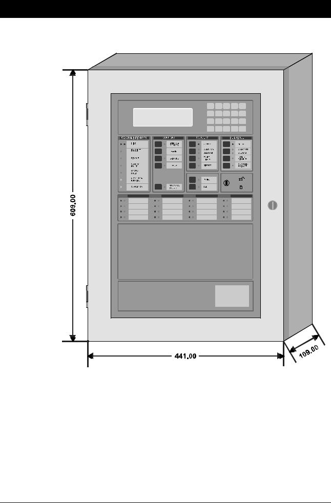
3. DIMENSIONS OF THE FIRE PANEL
Figure 1: Panel dimensions (cabinet size A)
−− |
Cabinet size B: 804 x 441 x 109 (H x W x D) |
Cabinet size C: 473.5 x 441 x 109 (H x W x D)
All dimensions are in mm
10 |
FP/FR2000 V4.5: Installation and Commissioning Manual |
 Loading...