


CS350
Installation Instructions
This manual contains installation details for the CS350 control panels.
It provides the basic programming and installation information required by technicians and engineers.
14 1791 999 |
1 |
|
|
Downloaded from: http://www.guardianalarms.net

2 |
14 1791 999 |
|
|

|
CONTENTS |
FEATURES .................................................................................................................................... |
3 |
KEYPAD INSTALLATION ........................................................................................................... |
4-5 |
WIRING SPECIFICATIONS ........................................................................................................... |
5 |
POWERING UP PANEL ................................................................................................................. |
6 |
HOW TO PROGRAMME ................................................................................................................ |
7 |
PROGRAMMING MAP ................................................................................................................... |
8 |
PROGRAMMING FUNCTIONS ................................................................................................... |
11 |
PERIDIAX FEATURE ................................................................................................................... |
19 |
PROGRAMMING TEXT ............................................................................................................... |
20 |
RETURNING TO FACTORY DEFAULT ...................................................................................... |
21 |
QUICK CODES ............................................................................................................................ |
21 |
ZONE WIRING OPTIONS ............................................................................................................ |
22 |
WIRING OF SIRENS .................................................................................................................... |
23 |
WIRING OF OUTPUTS |
|
RELAYS ........................................................................................................................... |
24 |
DIGITAL COMMUNICATORS ......................................................................................... |
24 |
FIRE DETECTORS ......................................................................................................... |
24 |
LIST WITH SHORT CODES ........................................................................................................ |
25 |
DEFAULT CHART ........................................................................................................................ |
26 |
PROBLEM SOLVING ................................................................................................................... |
27 |
TECHNICAL SPECIFICATION .................................................................................................... |
29 |
MAIN PANEL WIRING DIAGRAM ............................................................................................... |
30 |
|
Features |
FEATURES
The CS350 is a microcomputer based alarm control panel operating from remote keypads, and has the following features:
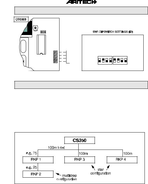
λ Facility for up to 4 CD3008 remote keypads... one CD3008 is supplied with the panel.
λ6 freely programmable dual zones.
λAuxiliary tamper input.
λSupervised bell tamper input.
λ Digital communicator fault input... reprogrammable to include remote engineer reset.
λNew perimeter system capability which provides local alarms for perimeter zone activations. This can reduce false alarms considerably. Exremely useful with inertia shock sensors.
λ4 freely programmable open collector outputs.
λ2 freely programmable high current outputs (eg. to control sirens).
λ LCD with freely programmable zone names... up to 12 characters.
λBattery input monitored.
λFour user codes.
See Programming Functions on page 14 for zone (Input) and page 15 for output types.
14 1791 999 |
3 |
|
|

Keypad Installation
3
CD3008
LIFT
2
PUSH
PUSH IN CLIP WITH
SCREW DRIVER AND
LIFT UP LID
1 |
REMOVE SCREW |
|
IF FITTED |
||
|
Figure 1.
CD3008
ADJUSTMENT |
DIPSWITCHES |
|
DISPLAY-CONTRAST |
FOR KEYPAD ID |
CABLE ENTRY |
|
|
FROM TOP |
MOUNTING HOLE

SPARE SCREW 

 TO FIX COVER
ONTO BASE
MIN |
MAX |
ON |
|
|
SD |
|
|
1 |
2 |
3 |
4 |
Figure 2.


 MOUNTING HOLE
PUSH CLAMP
 GENTLY TO
REMOVE PCB
CABLE ENTRY
FROM BACK
D
C
B
A

 MOUNTING HOLE
CABLE ENTRY
FROM BOTTOM
4 |
14 1791 999 |
|
|
Keypad Installation
SW1
MAX |
ON |
|
|
SD |
|
1 |
2 |
3 |
4 |
|
|
|
|
ON |
|
|
|
|
|
|
|
|
|
|
|
|
|
|
|
|
Control panel |
|
|
|
|
|
|
|
|
|
|
|
|
|
|
|
|
||
|
|
|
|
|
|
|
|
|
|
|
|
|
|
|
|
|
|||
|
OFF |
1 2 3 4 |
|
1 2 3 4 |
|||||||||||||||
|
Terminal 5 |
|
Keypad 1 |
|
Keypad 2 |
||||||||||||||
D |
|
15 |
|
|
|
(all off) |
|
|
|
|
|
|
|
|
|||||
C |
14 |
ON |
|
|
|
|
|
|
|
|
B |
13 |
|
|
|
|
|
|
|
|
|
|
|
|
|
|
|
|
|
|
||
A |
12 |
OFF |
1 |
2 |
3 |
4 |
1 |
2 |
3 |
4 |
|
|
CD3008 |
Keypad 3 Keypad 4 |
Figure 3. |
Figure 4. |
Wiring Specifications
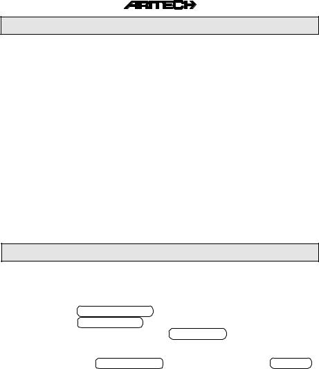
Connect the additional keypads either using a STAR or MULTIDROP configuration.
MULTIDROP |
the keypads are 'daisy chained' together, each keypad being connected in parallel |
|
to the one before it. |
STAR |
each keypad is wired back separately to the control panel terminals. |
Any combination of the above wiring methods is allowed with the restriction that the total cable length on each of the wiring loops (either multidrop or star) is restricted to 100m.
The following diagram shows how 4 RKPs may be connected using both methods.
Figure 5.
14 1791 999 |
5 |
|
|

Powering Up Panel
Connection of the control panel and the remote keypad in the following sequence allows the engineer to establish that the control panel is working correctly.
Connection sequence:
1.Before installing the remote keypad (RKP) at it's designated position, it may be connected at the control panel, to enable the engineer to commission the system.
2.Check that the ID for the RKP is set correctly... one keypad has to have ID1 (refer to Diagram 2).
3.Connect the RKP to the panel as shown in Diagram 3.
4.Replace the cover of the RKP and ensure that the tamper switch in the panel is closed.
5.Apply mains power to the panel. The system will power up in armed state (Factory Programme Setting). If any zones are open at power up, the audibles will activate. The panel
defaults to the language select prompt when switched on for the first time [ UK/IRL Press 1]. Enter [ ] and [1] to select English language. Note that this also happens after returning to factory default. See page 21 for more details.
6. Enter the Default User Security Code [1][1][2][2] at the keypad to disarm the system. The keypad display shows DISARMING and the audibles, if sounding, will stop. Display then shows any zones which are open and caused it to alarm. If [0] key is pressed at this stage, the display will show FINISHED? . Enter ACCEPT [ ] to finish with operator menu.
7.The display shows Time/Date and the system is now disarmed.
8.Enter [1][2][7][8] (Default Engineer Code) to enter Engineer Mode and to change programme
parameters. See the Programming Map and Programming Functions for operational details. How to programme is detailed on page 7.
9. Each time the system is powered down the panel memorizes it's current state, i.e. whether armed, disarmed, partguard, etc. and will restore to that state when powered-up again.
6 |
14 1791 999 |
|
|
HOW TO PROGRAMME
All programmed features can be changed. The structure and position of the programming options are illustrated in the Programming Map on the next page. Features and options are grouped together and allocated to 6 main menu blocks:
1 MAINTENANCE |
|
4 |
ZONES |
|
|
|
|
2 TIMERS |
|
5 OUTPUTS/REMOTES |
|
|
|
|
|
3 USERS |
|
6 |
MISCELLANEOUS |
Once in Engineer Mode, the blocks can be accessed by 'stepping' through the menu blocks and accepting the option shown in the display. The keys used for programme selections are defined as follows:
[ ] stepping forward to next block or programming option [ ] returning to previous block or programming option
[ ] enter programming block - enter programming option - confirm changes - accept option [X] quit programming block - quit programming option - reject changes
PROGRAMMING EXAMPLE
Adding Additional Keypads
After have installed the additional keypads - mind the correct dipswitch ID setting - go to the Engineer Programming Mode and proceed as follows:
1.Use the [ ] key till OUTPUTS/REMOTES is displayed then enter [ ] .
2.Use the [ ] key till INSTALL REMOTE is displayed then enter [ ] .
3. The display shows the keypads connected, eg. REMOTE k k . Confirm [ ] these changes when they are correct. If not correct, verify the wiring to the keypad and dipswitch ID settings. The keypad must be powerless when changing dipswitch settings.
4.The display now shows INSTALL REMOTE . Quit programming blocks [X] till GOODBYE is displayed. Now accept [ ] to leave the Engineer Programming Mode.
14 1791 999 |
7 |
|
|

CS350 PROGRAMMIMG MAP V1.0
1 |
|
1 |
Engineer Log |
|
|
Display Log |
||
|
|
|
||||||
|
|
|
|
|
|
|
|
Clear Log |
|
|
|
|
|
|
|
|
|
|
|
|
|
|
|
|
|
Maintenance Menu |
|
|
|
|
|
|
|
|
|
|
|
|
|
|
|
|
|
|
|
|
|
2 |
Output Test |
|
|
nn Low |
|
|
|
|
|
|
||||
|
|
|
|
|
|
|
|
or |
|
|
|
|
|
|
|
|
|
|
|
|
|
|
|
|
|
nn High |
|
|
|
|
|
|
|
|
|
|
|
|
|
|
|
|
|
|
MAINTENANCE |
|
3 |
Show Open Zones |
|
|
All Closed |
||
|
|
|
||||||
|
|
|
|
|
|
|
|
or |
|
|
|
|
|
|
|
|
|
|
|
|
|
|
|
|
|
nn Zone |
|
|
|
|
|
|
|
|
|
|
|
|
4 |
Walk Test |
|
|
Walk Test nn |
|
|
|
|
|
|
||||
|
|
|
|
|
|
|
|
|
|
|
|
5 |
LED Test |
|
|
Testing LEDs |
|
|
|
|
|
|
||||
|
|
|
|
|
|
|
|
|
|
|
|
|
Main Menu |
|
|
||
|
|
|
|
|
|
|||
|
|
|
|
|
|
|
|
|
|
|
|
|
|
|
|
|
|
2
 1 Entry Time nn
2Exit Time nn
|
|
|
|
|
|
|
|
|
|
|
|
|
|
|
|
|
|
|
|
|
|
3 |
Split Time OFF/ON |
|
|
|
|
||
|
|
|
|
|
|
|
|
|
|
|
|
|
|
|
|
|
|
|
|
|
|
|
4 |
Bell Times |
|
|
|
Bell Cutout nn |
|
|
|
|
|
|
|
|
|
|
|
|
||||
|
|
|
|
|
|
|
|
|
|
|
|
|
|
Bel Delay nn |
|
|
|
|
|
|
|
|
|
|
|
|
|
|
All Bells Cut ON/OFF |
|
|
|
TIMERS |
|
|
|
|
|
Dig Cutout ON/OFF |
|||||
|
|
|
|
|
|
|
|
|
|
|
|
|
|
Perim.Bell Cutout nn |
|
|
|
|
|
|
|
|
|
|
|
|
|
|
Timers Menu |
|
|
|
|
|
|
|
|
|
|
|
|
|
|
|
|
|
|
|
|
|
|
|
5 |
Time hh:mm |
|
|
|
Time hh:mm |
|
|
|
|
|
|
|
|
|
|
|
|
||||
|
|
|
|
|
|
|
|
|
|
|
|
|
|
|
|
|
|
|
|
|
|
|
6 |
Date dd/mm/yy |
|
|
|
Date dd/mm/yy |
|
|
|
|
|
|
|
|
|
|
|
|
||||
|
|
|
|
|
|
|
|
|
|
|
|
|
|
|
|
|
|
|
|
|
|
|
|
|
|
|
|
|
|
|
|
|
|
|
|
|
|
7 |
Summertime |
|
|
|
Forward Date |
|
|
|
|
|
|
|
|
|
|
|
|
||||
|
|
|
|
|
|
|
|
|
|
|
|
|
|
Backward Date |
|
|
|
|
|
|
|
|
|
|
|
|
|
|
|
|
|
|
|
|
|
|
|
|
|
|
|
|
|
Summertime ON/OFF |
|
|
|
|
|
|
|
|
|
Main Menu |
|
|
|
Timers Menu |
|
|
|
|
|
|
|
|
|
|
|
|
|
|
|
|
|
|
|
|
|
|
|
|
|
|
|
|
|
|
|
|
|
|
3 |
|
|
|
|
1 |
|
|
|
|
Change Codes |
|
|
|
|
|
|
|
|
|
|
|
|
||||
|
|
|
|
|
|
|
|
|
|
|
|
|
|
xx Code Unused |
|
|
|
|
|
|
|
|
|
|
|
|
|
|
|
|
|
|
|
|
|
|
|
|
|
|
|
|
|
New Code |
|
|
|
|
|
|
|
|
|
|
|
|
|
|
Verify |
|
|
|
|
|
|
|
|
|
|
|
|
|
|
Error |
|
|
|
|
|
|
|
|
|
|
|
|
|
||
|
|
|
|
|
|
|
|
|
|
|
|
|
||
|
|
|
|
|
|
|
|
2 |
Code Privilege |
|
|
|
01 Fs Us . . . . . . OK |
|
|
|
|
|
|
|
|
|
|
|
|
||||
|
|
|
|
|
|
|
|
|
|
|
|
|
|
02 . . . . . . . . . . . OK |
|
|
|
|
|
|
|
|
|
|
|
|
|
|
|
|
|
|
|
|
|
|
|
|
|
|
|
|
|
03 . . . . . . . . . . . OK |
|
|
|
|
|
|
|
|
|
|
|
|
|
|
04 . . . . . . . . . . . OK |
|
|
|
USERS |
|
|
|
|
|
|
Leave this |
||||
|
|
|
|
|
|
|
|
|
|
|
|
|
||
|
|
|
|
|
|
|
|
|
|
|
|
|
|
|
|
|
|
|
|
|
|
|
3 |
Engineer Code |
|
|
|
New Code |
|
|
|
|
|
|
|
|
|
|
|
|
||||
|
|
|
|
|
|
|
|
|
|
|
|
|
|
Verify |
|
|
|
|
|
|
|
|
|
|
|
|
|
|
|
|
|
|
|
|
|
|
|
|
|
|
|
|
|
Error |
|
|
|
|
|
|
|
|
|
|
|
|
|
||
|
|
|
|
|
|
|
|
|
|
|
|
|||
|
|
|
|
|
|
|
|
4 |
Duress Code |
|
|
|
New Code |
|
|
|
|
|
|
|
|
|
|
|
|
||||
|
|
|
|
|
|
|
|
|
|
|
|
|
|
Verify |
|
|
|
|
|
|
|
|
|
|
|
|
|
|
Error |
|
|
8 |
|
|
|
|
|
5 |
Code Count nn |
|
|
|
|
|
|
|
|
|
|
|
|
|
|
|
|
||||
|
|
|
|
|
|
|
|
|
|
|
|
|
|
|
|
|
|
|
|
|
|
|
|
||||||
|
|
|
|
|
|
|
6 |
Open Zones ON/OFF |
|
|
||||
|
|
|
|
|
|
|
|
|
|
|
|
|
|
|
|
|
|
|
|
|
|
|
|
|
|
|
|
|
|
|
|
|
|
|
|
|
|
|
Main Menu |
|
|
|
|
|
|
|
|
|
|
|
|
|
|
|
|
|
|
||
|
|
|
|
|
|
|
|
|
|
|
|
|
|
|
|
|
|
|
|
|
|
|
|
|
|
|
|
|
|
xx Code In Use
USER ATTRIBUTES
Mn=Manager
In=Inhibit
Ps=Part Set
Us=Unset
Fs=Full Set
14 1791 999

CS350 Programming Map
4 |
|
1 |
Zone Type |
|
01 Alarm |
|
|
|
ZONE TYPES |
||
|
|
|
|
|
|||||||
|
|
|
|
|
|
|
0x . . . . . . . . . . . . |
|
|
|
|
|
|
|
|
|
|
|
06 . . . . . . . . . . . . |
|
|
|
Unused |
|
|
|
|
|
|
|
Leave this |
|
|
|
Tamper |
|
|
|
|
|
|
|
|
|
|
|
PA |
|
|
|
|
|
|
|
|
|
|
|
|
|
|
|
2 |
Zone Attributes |
|
01 In |
|
|
|
Key |
|
|
|
|
|
|
|
|
0x . . . . . . . . . . . . |
|
|
|
Fire |
|
|
|
|
|
|
|
06 . . . . . . . . . . . . |
|
|
|
Exit/Entry |
|
|
|
|
|
|
|
Leave this |
|
|
|
Alarm |
|
|
|
|
|
|
|
|
|
|
||
|
|
|
|
|
|
|
|
|
|
|
Keypad Lock |
|
|
|
|
|
|
|
|
|
|
|
Key Inf=Infinite Entry |
|
|
|
|
|
|
|
|
|
|
|
|
|
|
|
|
|
|
|
|
|
|
|
Exit Trm=Exit Terminator |
|
|
|
|
|
|
|
|
|
|
|
|
|
|
|
|
|
|
|
|
|
|
||
ZONES |
|
3 |
Shock Zones |
|
nn Gross. x Pls y |
|
|
|
ZONE ATTRIBUTES |
||
|
|
|
|
|
|||||||
|
|
|
|
|
|
|
nn Wrong Type |
|
|
|
Ls=Local Alarm Shock |
|
|
|
|
|
|
|
|
|
|
|
|
|
|
|
4 |
Zone Name |
|
|
|
|
|
La=Local Alarm Contact |
|
|
|
|
|
|
|
|
|
||||
|
|
|
|
|
|
|
|
|
|
|
In=Inhibit |
|
|
|
5 |
Loop Type : Alarm |
|
|
|
|
|
24=24 hours |
|
|
|
|
|
Loop Type : Dual |
|
|
|
|
|
Pg=Partguard |
|
|
|
|
|
|
|
|
|
|
|
|
So=Soak Test |
|
|
|
|
|
|
|
|
|
|
|
|
|
|
|
|
|
|
|
|
|
|
|
Ac=Access |
|
|
|
|
|
|
|
|
|
|
|
|
|
|
|
|
|
|
|
|
|
|
|
Ch=Chime |
|
|
|
|
|
|
|
|
|
|
|
|
|
|
|
|
|
|
|
|
|
|
|
KEY ZONE ATTRIBUTES |
|
|
|
|
|
|
|
|
|
|
|
|
|
|
|
|
|
|
|
|
|
|
|
Fs=Full Set |
|
|
|
|
|
|
|
|
|
|
|
Ps=Part Set |
|
|
|
|
|
|
|
|
|
|
|
Us=Unset |
|
|
|
|
|
|
|
|
|
|
|
Pu=Pulsed |
|
|
|
|
Main Menu |
|
|
|
|
|
Qs=Quick Set |
|
|
|
|
|
|
|
|
|
|
|||
|
|
|
|
|
|
|
|
|
|
|
|
|
|
|
|
|
|
|
|
|
|
|
|
5 |
|
1 |
Output Type |
|
01 Disarm/Arm |
|
|
|
OUTPUT TYPES |
||
|
|
|
|
|
|||||||
|
|
|
|
|
|||||||
|
|
|
|
|
|
|
0x . . . . . . . . . . . . |
|
|
|
|
|
|
|
|
|
|
|
|
|
|
|
|
|
|
|
|
|
|
|
06 . . . . . . . . . . . . |
|
|
|
Disarm/Arm |
|
|
|
|
|
|
|
|
|
|
|
Alarm |
|
|
|
|
|
|
|
|
|
|
|
|
|
|
|
|
|
|
|
|
|
|
|
P.A. |
|
|
|
|
|
|
|
|
|
|
|
Fire |
|
|
|
|
|
|
|
|
|
|
|
Tamper |
OUTPUTS / |
|
2 |
Install Remote |
|
Remote kk** |
|
|
|
Latch |
||
|
|
|
|
|
|||||||
REMOTES |
|
|
|
|
|
|
|
|
|
Fire Detect Reset |
|
|
|
|
|
|
|
|
|
|
|||
|
|
|
|
|
|
|
k=CD3008 |
Buzzer |
|||
|
|
|
|
|
|
|
|
|
|
|
Int.Bell |
|
|
|
|
|
|
|
|
|
|
|
Ext.Bell |
|
|
|
|
|
|
|
|
|
|
|
Partguard |
|
|
|
|
|
|
|
|
|
|
|
System Clear |
|
|
|
|
|
|
|
|
|
|
|
Trouble |
|
|
|
|
Main Menu |
|
|
|
|
|
Perim.Alarm |
|
|
|
|
|
|
|
|
|
|
|||
|
|
|
|
|
|
|
|
|
|
|
Unused |
|
|
|
|
|
|
|
|
|
|
|
|
|
|
|
|
|
|
|
|
|
|
|
Clear |
|
|
|
|
|
|
|
|
|
|
|
|
14 1791 999 |
9 |
|
|

CS350 Programming Map
6 |
|
1 |
Arm/Disarm Menu |
|
User Walk ON/OFF |
|
|
|
No Forced Arming |
||||
|
|
|
|
|
|
||||||||
|
|
|
|
|
|
|
|
|
Forced Arm Opts |
|
|
|
Keep Inhibits |
|
|
|
|
|
|
|
|
|
|
|
|
||
|
|
|
|
|
|
|
|
|
Rearm Options |
|
|
|
Clear when closed |
|
|
|
|
|
|
|
|
|
|
|
|
||
|
|
|
|
|
|
|
|
|
ArmedDisplay ON/OFF |
|
|
|
Clear after exit |
|
|
|
|
|
|
|
|
|
|
|
|
||
|
|
|
|
|
|
|
|
|
Exit Fault Buzzer/Bell |
|
|
|
|
|
|
|
|
|
|
|
|
|
|
|
|
|
|
|
|
|
|
|
|
|
|
|
Final Door ON/OFF |
|
|
|
|
|
|
|
|
|
|
|
|
|
|
|
|
|
|
|
|
|
|
|
|
|
|
|
Miscellaneous Menu |
|
|
|
Always rearm |
|
|
|
|
|
|
|
|
|
|
|
|
||
|
|
|
|
|
|
|
|
|
|
|
|
|
Never rearm |
|
|
|
|
|
|
|
|
|
|
|
|
|
|
|
|
|
|
|
|
|
|
|
|
|
|
|
Rearm 1 to 8 Times |
|
|
|
2 |
P.A. Menu |
|
P.A. Silent/Bells |
|
|
|
|
|||
|
|
|
|
|
|
|
|
||||||
|
|
|
|
|
|
|
|
||||||
|
|
|
|
|
|
|
|
|
PA, LF Silent/Bells |
|
|
|
|
|
|
|
|
|
|
|
|
|
|
|
|
|
|
|
|
|
|
|
|
|
|
|
PA ON/OFF |
|
|
|
|
|
|
|
|
|
|
|
|
|
Miscellaneous Menu |
|
|
|
|
|
|
|
|
|
|
|
|
|
|
|
|
|
|
|
|
|
|
|
|
|
|
|
|
|
|
|
|
|
|
|
3 |
Partgd/Chime |
|
Timed Partgd ON/OFF |
|
|
|
|
|||
|
|
|
|
|
|
|
|
||||||
|
|
|
|
|
|
|
|
|
Access—>EE/Access |
|
|
|
|
|
|
|
|
|
|
|
|
|
|
|
|
|
|
|
|
|
|
|
|
|
|
|
Partgd Digi ON/OFF |
|
|
|
|
|
|
|
|
|
|
|
|
|
Latched Chime ON/OFF |
|
|
|
|
|
|
|
|
|
|
|
|
|
Int.Bell Chime ON/OFF |
|
|
|
|
|
|
|
|
|
|
|
|
|
Miscellaneous Menu |
|
|
|
|
|
|
|
|
|
|
|
|
|
|
|
|
|
|
|
|
|
|
|
|
|
|
|
|
|
|
|
|
|
|
|
4 |
Eng. Reset Menu |
|
Reset Code/FTC or Code Only |
|
||||||
|
|
|
|
|
|||||||||
|
|
|
|
|
|
|
|
|
P.A. Reset ON/OFF |
|
|||
|
|
|
|
|
|
|
|
|
|
||||
|
|
|
|
|
|
|
|
|
Tamper Reset ON/OFF |
|
|||
MISCELLANEOUS |
|
|
|
|
|
|
|
Alarm Reset ON/OFF |
|
||||
|
|
|
|
|
|
|
|
|
Clear Engineer Reset |
|
|||
|
|
|
|
|
|
|
|
|
Miscellaneous Menu |
|
|||
|
|
|
|
|
|
|
|
|
|
|
|
|
|
|
|
|
|
|
|
|
|
|
|
|
|
|
|
|
|
|
5 |
Warnings |
|
PF Buzzer ON/OFF |
|
|
|
|
|||
|
|
|
|
|
|
|
|
||||||
|
|
|
|
|
|
|
|
|
LF Buzzer ON/OFF |
|
|
|
|
|
|
|
|
|
|
|
|
|
Miscellaneous Menu |
|
|
|
|
|
|
|
|
|
|
|
|
|
|
|
|
|
|
|
|
|
|
|
|
|
|
|
|
|
|
|
|
|
|
|
6 |
Factory Prog Menu |
|
Engineer Lock ON/OFF |
|
|
|
|
|||
|
|
|
|
|
|
|
|
||||||
|
|
|
|
|
|
|
|
|
Miscellaneous Menu |
|
|
|
|
|
|
|
|
|
|
|
|
|
|
|
|
|
|
|
|
|
|
|
|
|
|
|
|
|
|
|
|
|
|
|
7 |
Change |
Language |
|
English |
|
|
|
|
||
|
|
|
|
|
|
|
|
||||||
|
|
|
|
|
|
|
|
|
Nederlands |
|
|
|
|
|
|
|
|
|
|
|
|
|
|
|
|
|
|
|
|
|
|
|
|
|
|
|
Francais |
|
|
|
|
|
|
|
|
|
|
|
|
|
Italiano |
|
|
|
|
|
|
|
|
|
|
|
|
|
|
|
|
|
|
|
|
|
8 |
SysClear Inputs |
|
System Clear Mains ON/OFF |
|
||||||
|
|
|
|
|
|||||||||
|
|
|
|
|
|
|
|
|
System Clear Battery ON/OFF |
|
|||
|
|
|
|
|
|
|
|
|
|
||||
|
|
|
|
|
|
|
|
|
System Clear Fuse ON/OFF |
|
|||
|
|
|
|
|
|
|
|
|
System Clear Accs+EE ON/OFF |
|
|||
|
|
|
|
|
|
Main Menu |
|
Miscellaneous Menu |
|
||||
|
|
|
|
|
|
|
|
||||||
|
|
|
|
|
|
|
|
|
|
|
|
|
|
|
|
|
|
|
|
|
|
|
|
|
|
|
|
GOODBYE
10 |
14 1791 999 |
|
|
 Loading...