

Page 1

ML 99 IX AUSML 99 IX AUS
English
Operating Instructions
OVEN
Operating Instructions,1
Warnings,2
Assistance,2
Description of the appliance,3
Description of the appliance,3
Installation,4
Start-up and use,6
Modes,9
Precautions and tips,10
Maintenance and care,11
Contents
Page 2

Warnings
WARNING: The appliance and its accessible parts
become hot during use. Care should be taken to
avoid touching heating elements. Children less than 8
years of age shall be kept away unless continuously
supervised. This appliance can be used by children
aged from 8 years and above and persons with
reduced physical, sensory or mental capabilities or
lack of experience and knowledge if they have been
given supervision or instruction concerning use of the
appliance in a safe way and understand the hazards
involved. Children shall not play with the appliance.
Cleaning and user maintenance shall not be made
by children without supervision.
Do not use harsh abrasive cleaners or sharp metal
scrapers to clean the oven door glass since they can
scratch the surface, which may result in shattering of
the glass.
Assistance
Warning:
The appliance is tted with an automatic diagnostic system which detects
any malfunctions. Malfunctions are displayed by messages of the following
type: ”F” followed by numbers.
Call for technical assistance should a malfunction occur.
! Never use the services of an unauthorised technician.
Please have the following information to hand:
• The type of problem encountered.
• The appliance model (Mod.).
• The serial number (S/N).
The latter two pieces of information can be found on the data plate located
on the appliance.
Never use steam cleaners or pressure cleaners on
the appliance.
WARNING: Ensure that the appliance is switched
off before replacing the lamp to avoid the possibility
of electric shock.
! When you place the rack inside, make sure that the
stop is directed upwards and in the back of the cavity.
2
Page 3
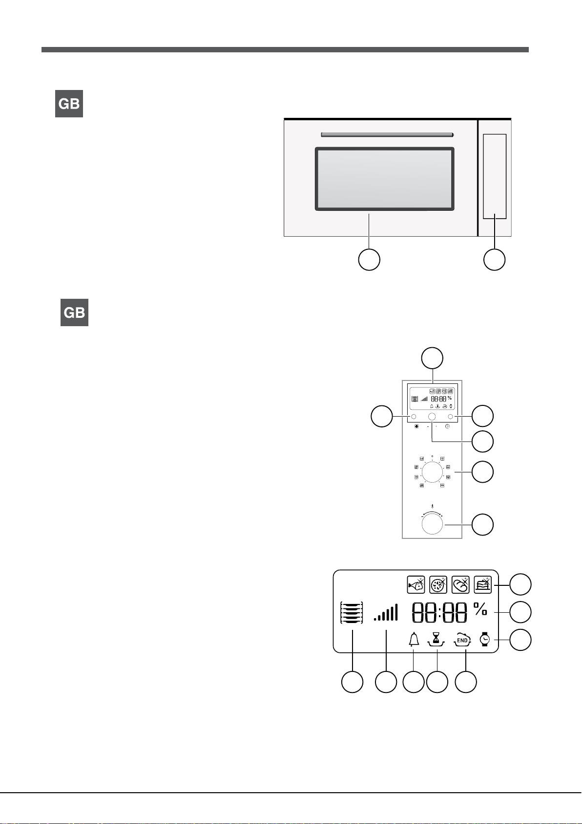
Description of the appliance
Overall view
1 Control panel
2 Glass oven door
12
Description of the appliance
Control panel
1 DISPLAY
2 TIME SETTING button
3 TIMER knob
4 SELECTOR knob
5 THERMOSTAT knob
6 LIGHT Button
Display
7 AUTOMATIC/ECO COOKING MODE icons
8 TEMPERATURE and TIME digits
9 CLOCK Icon
10 END OF COOKING Icon
11 DURATION Icon
12 TIMER Icon
13 Preheating indicator
14 Recommended rack position icon
1
6
2
3
4
5
7
8
9
1011121314
3
Page 4
GB
Installation
! Please keep this instruction booklet in a safe place for future reference. If
the appliance is sold, given away or moved, please make sure the booklet is
also passed on to the new owners so that they may benet from the advice
contained within it.
! Please read this instruction manual carefully: it contains important information
concerning the safe operation, installation and maintenance of the appliance.
472 mm
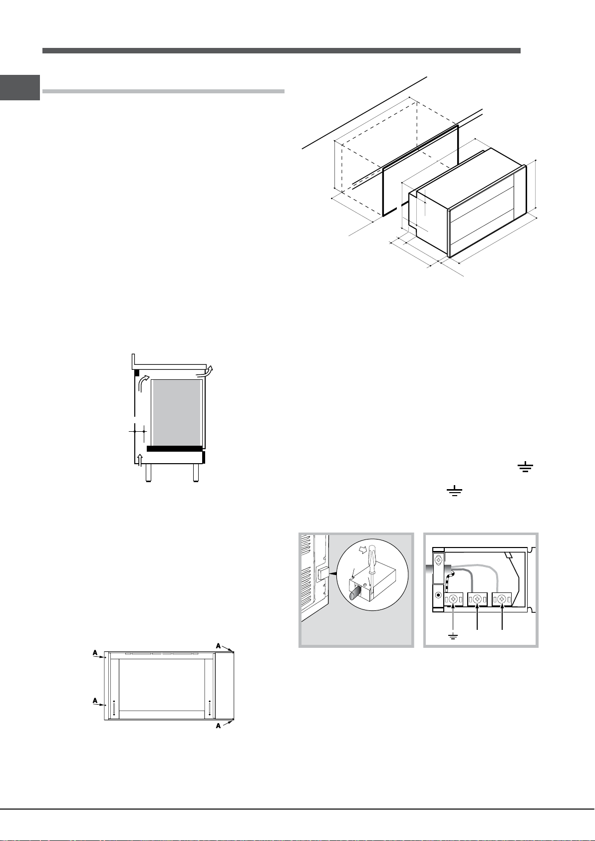
Positioning
! Do not let children play with the packaging material; it should be disposed
of in accordance with local separated waste collection standards (see
Precautions and tips).
! The appliance must be installed by a qualied professional in accordance
with the instructions provided. Incorrect installation may damage property or
cause harm to people or animals.
Built-in appliances
To ensure the proper working order of the built-in appliance, the kitchen unit
must be of a suitable size.
The sizes of the unit for installing the cooker under a worktop or in a column
unit are shown in gure.
Electrical connection
Those ovens equipped with a three-pole power supply cable are designed to
operate with an alternating current with the voltage and frequency indicated
on the data plate (located on the appliance) and in the instruction manual.
The wire for earthing the appliance is yellow-green in colour.
Replacing the cable
Use a rubber cable of the type H05VV-F with a suitable cross section 3 x
1.5 mm².
The yellow-green earth wire must be 2-3 cm longer than the other wires.
min.
550
m
m
0
86
mm
0
85
475 mm
m
m
52
469 mm
78
78
447
525
m
m
m
m
22
m
m
895 m
m
min. 45 mm.
To provide adequate ventilation, there must be appropriate ventilation openings
in the front bottom and the top part of the cabinet (an intake opening on the
bottom of at least 200 cm2, and an exhaust opening of at least 90 cm2). The
unit panels next to the cooker must be heat resistant. In the case of veneered
wood units, glues must be resistant to a temperature of 120 °C. In accordance
with safety standards, once the appliance has been mounted, there must be
no possible contact with electrical parts. Any protective parts must be secured
so that they can only be removed with the use of tools.
Fastening the oven
Insert the appliance into the compartment; open the oven door and fasten
the oven to the cabinet using the four screws “A”, remembering to place the
special spacers provided between the hole and the screw itself.
Opening the terminal board:
• Using a screwdriver, prise on the side tabs of the terminal board cover;
• Pull open the cover of the terminal board.
To install the cable, proceed as follows:
• Remove the wire clamp screw and the three contact screws L-N-
• Fasten the wires beneath the screwheads using the following colour
scheme: Blue (N) Brown (L) Yellow-Green
• Fasten the supply cable in place with the clamp and close the cover of the
terminal board.
NL
Connecting the supply cable to the mains
Install a standardised plug corresponding to the load indicated on the data
plate. When connecting the cable directly to the mains, install an omnipolar
circuit-breaker with a minimum contact opening of 3 mm between the appliance
and the mains. The omnipolar circuit breaker should be sized according to
the load and should comply with current regulations (the earth wire should
not be interrupted by the circuit breaker).
The supply cable should be positioned so that it does not reach a temperature
of more than 50°C with respect to the room temperature, anywhere along
its length.
4
Page 5

Before making the connection, check that:
• The electrical safety of this appliance can only be guaranteed if the cooker
is correctly and efciently earthed, in compliance with regulations on
electrical safety. Always ensure that the earthing is efcient; if you have any
doubts call in a qualied technician to check the system. The manufacturer
declines all responsibility for damage resulting from a system which has
not been earthed.
• Before plugging the appliance into the mains, check that the specications
indicated on the date plate (on the appliance and/or packaging) correspond
to those of the electrical mains system of your home.
• Check that the electrical capacity of the system and sockets will support
the maximum power of the appliance, as indicated on the data plate. If
you have any doubts, call in a qualied technician.
• If the socket and appliance plug are not compatible, have the socket
replaced with a suitable model by a qualied technician. The latter, in
particular, will also have to ensure that the cross section of the socket
cables are suitable for the power absorbed by the appliance. The use
of adapters, multiple sockets and/or extensions, is not recommended.
If their use cannot be avoided, remember to use only single or multiple
adapters and extensions which comply with current safety regulations. In
these cases, never exceed the maximum current capacity indicated on
the single adapter or extension and the maximum power indicated on the
multiple adapter.
! Once the appliance has been installed, the power supply cable and the
electrical socket must be easily accessible.
APPLIANCE SPECIFICATIONS
width 59,5 cm
Dimensions
Volume
Electrical
connections
Energy Label
and Ecodesign
height 32,9 cm
depth 39,4 cm
78 l
voltage: 220-240V ~ 50Hz
(see data plate)
maximum power absorbed 2800 W
Declared energy consumption
for Forced convection Class –
heating mode:
GB
ECO
! The cable must not be bent or compressed.
! The cable must be checked regularly and replaced by authorised technicians
only (see Assistance).
! The manufacturer declines any liability should these safety measures
not be observed.
5
Page 6

GB
Start-up and use
WARNING! The oven is provided
with a stop system to extract the
racks and prevent them from
coming out of the oven (1).
As shown in the drawing, to extract
them completely, simply lift the
racks, holding them on the front
part, and pull (2).
! The rst time you use your appliance, heat the empty oven with its door
closed at its maximum temperature for at least half an hour. Ensure that the
room is well ventilated before switching the oven off and opening the oven
door. The appliance may emit a slightly unpleasant odour caused by protective
substances used during the manufacturing process burning away.
! In order to optimise the cooking performance, when starting the selected
function, product settings will be applied that could cause a delayed start of
the fan and heating elements.
Setting the clock
! The clock may be set when the oven is switched off or when it is switched
on, provided that a the end time of a cooking cycle has not been programmed
previously.
4. The DISPLAY will show the icon , which indicates the recommended
shelf level for the tray.
5. During cooking it is always possible to:
- Change the cooking mode by turning the SELECTOR knob.
- Change the temperature by turning the THERMOSTAT knob.
- set the cooking duration and the end cooking time (see Cooking Modes)
- Stop cooking by turning the SELECTOR knob to the “0” position.
6. The oven switches off automatically after two hours: this default period of
time is set for all cooking modes for safety reasons.
The cooking time may be modied (see Cooking Modes).
7. If a blackout occurs while the oven is already in operation, an automatic
system within the appliance will reactivate the cooking mode from where it
was interrupted as long as the temperature has not dropped below a certain
level. Programmed cooking modes which have not started will not be restored
and must be reprogrammed.
! There is no preheating stage for the BARBECUE mode.
! Never put objects directly on the bottom of the oven; this will prevent the
enamel coating from being damaged.
! Always place cookware on the rack(s) provided.
! The oven will begin its preheating phase after 2 seconds from selecting
the desired cycle.
1. Press the
digits on the display start to ash.
2. Turn the TIMER KNOB towards “ ” and “ ” to adjust the hour value.
3. Press the
begin to ash.
4. Turn the TIMER KNOB towards “ ” and “ ” to adjust the minute value.
5. Press the
Setting the timer
! This function does not interrupt cooking and does not affect the oven; it is
simply used to activate the buzzer when the set amount of time has elapsed.
1. Press the
on the display begin to ash.
2. Turn the TIMER KNOB towards “ ” and “ ” to adjust the minute value.
3. Press the
The display will then show the time as it counts down. When this period of
time has elapsed the buzzer will be activated.
Using the oven
! Before operating the product, remove all plastic lm from the sides of the
appliance.
! The rst time you use your appliance, heat the empty oven with its door
closed at its maximum temperature for at least half and hour. Ensure that the
room is well ventilated before switching the oven off and opening the oven
door. The appliance may emit a slightly unpleasant odour caused by protective
substances used during the manufacturing process burning away.
1. Select the desired cooking mode by turning the SELECTOR knob.
2. The oven begins its preheating stage and the preheating indicator lights up.
The temperature may be changed by turning the THERMOSTAT knob
3. When the preheating indicator
preheating process is complete: you may now place the food in the oven.
button several times until the icon and the rst two
button again until the other two digits on the DISPLAY
button again to conrm.
button several times until the icon and the three digits
button again to conrm.
switches off and a buzzer sounds the
Cooling ventilation
In order to cool down the external temperature of the oven, a cooling fan blows
a stream of air between the control panel and the oven door.
! Once the cooking has been completed, the cooling fan remains on until the
oven has cooled down sufciently.
Oven light
When the oven is not in operation, the lamp can be switched on at any time
by pressing the button
Modes
Manual cooking modes
! All cooking modes have a default cooking temperature which may be adjusted
manually between 40°C and 250°C as desired.
In the BARBECUE mode, the default power level value is indicated as a
percentage (%) And may also be adjusted manually.
MULTILEVEL mode
All heating elements and the fan are activated. Since the heat remains constant
throughout the oven, the air cooks and browns food in a uniform manner. A
maximum of two racks may be used at the same time.
BARBECUE mode
The top heating element is activated. By turning the THERMOSTAT knob, the
different power levels which may be set will appear on the DISPLAY; these
range between 5% and 100%. The high and direct temperature of the grill is
recommended for food which requires a high surface temperature. Always
cook in this mode with the oven door closed.
.
6
Page 7

! The cooking duration may be changed by ±10 minutes.
GRATIN mode
The top heating element is activated and the fan begins to operate. During part
of the cycle the circular heating element is also activated. This combination
of features increases the effectiveness of the unidirectional thermal radiation
provided by the heating elements through forced circulation of the air
throughout the oven.
This helps prevent food from burning on the surface and allows the heat to
penetrate right into the food. Always cook in this mode with the oven door
closed.
ECO Programme
The back heating element is turned on and the fan starts working, ensuring
a smooth and uniform heat level inside the oven.
This programme is indicated for slow cooking of any type of food with
temperatures which can be set up to a maximum of 200°C; the programme
is also suitable for heating food and to complete the cooking process.
The programme is particularly suitable for the slow cooking of meat and sh,
as it allows you to have softer meat and save energy at the same time. For
a better energy effectiveness, when the product is turned on, the light stays
on only for 30 seconds; in order to turn the light back on, please press the
button
Spit roast (only available in certain models)
This accessory should only be used when cooking with the grill. Proceed as
follows: thread the meat you wish to cook onto the rod positioned across the
oven lengthwise, xing it in place with the adjustable forks supplied. Position
supports “A” and “B” in the relevant holes in dripping pan “E”, rest the groove
on the rod in slot “C” and use the guide rail to place the rack in the lowest
position in the oven; next position the rod in the rotisserie spit hole, sliding
the groove forwards to slot “D” (see gures). Start the rotisserie using the
SELECTOR knob set to cooking mod
or ;
Use this function to make pizza. Please see the following chapter for the
recipe and further details.
! The cooking duration may be changed by ±5 minutes.
Use this function to make bread. Please see the following chapter for the
recipe and further details.
This function is ideal for cooking desserts which are made using natural yeast,
baking powder and desserts which contain no yeast. Place the dish in the
oven while it is still cold. The dish may also be placed in a preheated oven.
! The cooking duration may be changed by ±10 minutes.
To obtain the best results, we recommend that you carefully observe the
instructions below:
• Follow the recipe.
• The weight of the dough should be between 500 g and 700 g.
• Lightly grease the dripping pan.
Recipe for PIZZA:
1 dripping pan on a low shelf level, hot or cold oven
Recipe for 3 pizzas weighing approximately 550 g: 1000 g our, 500 ml water,
20 g salt, 20 g sugar, 100 ml olive oil, 20 g fresh yeast (or 2 sachets of
powder yeast)
• Leavening at room temperature: 1 hour.
• Place inside hot or cold oven.
GB
PIZZA mode
BREAD mode
BAKING mode
PIZZA mode
• Start the
BREAD mode
To obtain the best results, we recommend that you carefully observe the
instructions below:
• Follow the recipe.
• Do not exceed the maximum weight of the dripping pan.
Automatic cooking modes
! The temperature are pre-set values, guaranteeing a perfect result
every time - automatically. These values cannot be adjusted and use the
C.O.P.® (Programmed Optimal Cooking) system. The cooking cycle stops
automatically and the oven indicates when the dish is cooked. You may start
cooking whether the oven has been preheated or not; we recommend that
you follow the guidelines provided by the
shelf to place the tray.
! When the cooking stage has been reached, the oven buzzer sounds.
! Do not open the oven door as this will disrupt the cooking time and
temperature.
GRILL mode
Use this function to cook beef, pork and lamb. Place the loaves inside the
oven while it is still cold. The dish may also be placed in a preheated oven.
icon when deciding on which
• Remember to pour 1,5 dl of cold water into the baking tray in position
5.
• The dough must be left to rise at room temperature for 1 – 1 ½ hours
(depending on the room temperature) or until the dough has doubled in
size.
Recipe for BREAD:
1 Dripping pan holding 1000 g Max, lower level
2 Dripping pans each holding 1000 g Max, medium and lower levels
Recipe for 1000 g of dough: 600 g our, 360 g water, 11g salt, 25 g fresh yeast
(or 2 sachets of powder yeast)
Method:
• Mix our and salt in a large bowl.
• Dilute yeast in lukewarm water (approximately 35 degrees).
• Make a small well in the mound of our.
• Pour in water and yeast mixture.
• Knead dough by stretching and folding it over itself with the palm of your
hand for 10 minutes until it has a uniform consistency and is not too sticky.
PIZZA cooking mode.
7
Page 8

GB
• Form the dough into a ball shape, place it in a large bowl and cover it with
transparent plastic wrap to prevent the surface of the dough from drying
out. Place the bowl inside and leave the dough to rise for approximately
1 hour (the dough should double in volume).
• Cut the dough into equal sized loaves.
• Place them in the dripping pan on oven paper.
• Cover the loaves with our.
• Make incisions on the loaves.
• Place the loaves inside the oven while it is still cold.
• Start the
• Once baked, leave the loaves on one of the grill racks until they have
cooled completely.
• For cleaning purposes, we recommend the use of water and vinegar.
BREAD cooking mode.
BARBECUE
• Place the rack in position 3 or 4. Position the food in the centre of the rack.
• We recommend that the power level is set to maximum. The top heating
element is regulated by a thermostat and may not always operate
constantly.
PIZZA
• Use a light aluminium pizza pan. Place it on the rack provided.
For a crispy crust, do not use the dripping pan as it prevents the crust from
forming by extending the total cooking time.
• If the pizza has a lot of toppings, we recommend adding the mozzarella
cheese on top of the pizza halfway through the cooking process.
Programming cooking
! A cooking mode must be selected before programming can take place.
Programming the cooking duration
1. Press the
digits on the DISPLAY begin to ash.
2. Turn the TIMER KNOB towards “
3. Press the
4. When the set time has elapsed, the text END appears on the DISPLAY,
the oven will stop cooking and a buzzer sounds.
• For example: it is 9:00 a.m. and a time of 1 hour and 15 minutes is
programmed. The programme will stop automatically at 10:15 a.m.
Setting the end time for a cooking mode
! A cooking duration must be set before the end cooking time can be scheduled.
1. Follow steps 1 to 3 to set the duration as detailed above.
2. Next, press the
the DISPLAY begin to ash.
3. Turn the TIMER KNOB towards “ ” and “ ” to adjust the hour value.
4. Press the
begin to ash.
5. Turn the TIMER KNOB towards “ ” and “ ” to adjust the minute value.
6. Press the
7. When the set time has elapsed, the text END appears on the DISPLAY,
the oven will stop cooking and a buzzer sounds.
button several times until the icon and the three
” and “ ” to adjust the duration.
button again to conrm.
button until the icon and the two digits on
button again until the other two digits on the DISPLAY
button again to conrm.
Programming has been set when the
illuminated. The DISPLAY shows the cooking end time and the cooking
duration alternately.
To cancel programming, turn the SELECTOR knob to the “0” position.
and buttons are
Practical cooking advice
! Do not place racks in position 1 and 5 during fan-assisted cooking. This is
because excessive direct heat can burn temperature sensitive foods.
! In the BARBECUE and GRATIN cooking modes, particularly when using the
rotisserie spit, place the dripping pan in position 1 to collect cooking residues
(fat and/or grease).
MULTILEVEL
• Use positions 2 and 4, placing the food which requires more heat on 2.
• Place the dripping pan on the bottom and the rack on top.
8
Page 9

Oven cooking advice table
Cooking
modes
Multilivel*
Barbecue*
Gratin*
Automatic
Pizza
Automatic
Bread
Automatic
baked cakes
Automatic
roast
Foods
Pizza on 2 racks
Pies on two racks/cakes on 2 racks
Sponge cake on 2 racks (on the dripping pan)
Roast chicken + potatoes
Lamb
Mackerel
Lasagne
Cream puffs on 2 racks
Biscuits on 2 racks
Cheese puffs on 2 racks
Savoury pies
Mackerel
Sole and cuttlefish
Squid and prawn kebabs
Cod fillet
Grilled vegetables
Veal steak
Sausages
Hamburgers
Toasted sandwiches (or toast)
Spit-roast chicken using rotisserie spit
(where present)
Spit-roast lamb using rotisserie spit
(where present)
Grilled chicken
Cuttlefish
Spit-roast chicken using rotisserie spit
(where present)
Spit-roast duck using rotisserie spit
(where present)
Roast veal or beef
Roast pork
Lamb
Pizza (see recipe)
Focaccia (bread dough)
Bread (see recipe)
Cakes made using leavened dough
Roasts
Weight
(Kg)
1+1
1
1
1
1
0,7
0,7
0,7
0,5
0,8
0,7
n°4 or 5
n°4 or 6
1
1
1,5
1
1,5
1,5
1
1
1
1
1
1
1
1
Weight
standard
guide rails
2 and 4
2 and 4
2 and 4
1 and 2/3
2
1 or 2
2
2 and 4
2 and 4
2 and 4
1 and 3
4
4
4
4
3 or 4
4
4
4
4
-
-
2
2
-
-
2
2
2
2
2
2
2
2
(Kg)
sliding
guide rails
1 and 3
1 and 3
1 and 3
1 and 3
1 and 3
1 and 3
1 and 3
1 and 3
1
1
1
3
3
3
3
2 or 3
3
3
3
3
-
-
2
2
-
-
2
2
2
2
2
2
2
2
Preheating
Yes
Yes
Yes
Yes
Yes
Yes
Yes
Yes
Yes
Yes
Yes
No
No
No
No
No
No
No
No
No
No
No
No
No
No
No
No
No
No
No
No
No
No
No
Recommended
temperature
(°C)
220-230
180
170
200-210
190-200
180
190-200
190
190
210
200
100%
100%
100%
100%
100%
100%
100%
100%
100%
100%
100%
210
200
210
210
210
210
210
-
-
-
-
-
Cooking
duration
(minutes)
20-25
30-35
20-25
65-75
45-50
30-35
35-40
20-25
10-20
20-25
20-30
15-20
10-15
8-10
10-15
15-20
15-20
15-20
10-12
3-5
70-80
70-80
50-60
30-35
70-80
60-70
60-75
70-80
40-45
23-33
23-33
60
35-55
60-80
GB
* The cooking times listed above are intended as guidelines only and may be modified according to personal tastes.
Oven preheating times are set as standard and may not be modified manually.
! ECO programme: This programme can be used for slow cooking of any type of food with temperatures which can be set up
to a maximum of 200°C; the programme is also suitable for heating food and to complete the cooking process
9
Page 10

Precautions and tips
! This appliance has been designed and manufactured in compliance with
international safety standards. The following warnings are provided for safety
reasons and must be read carefully.
General safety
• The appliance was designed for domestic use inside the home and is
not intended for commercial or industrial use.
• The appliance must not be installed outdoors, even in covered areas. It is
extremely dangerous to leave the appliance exposed to rain and storms.
• When moving or positioning the appliance, always use the handles
provided on the sides of the oven.
• Do not touch the appliance while barefoot or with wet or damp hands and
feet.
• The appliance must be used by adults only for the preparation of
food, in accordance with the instructions provided in this booklet.
Any other use of the appliance (e.g. for heating the room) constitutes
improper use and is dangerous. The manufacturer may not be held
responsible for any damage caused as a result of improper, incorrect
and unreasonable use of the appliance.
• Do not touch the heating elements or certain parts of the oven door
when the appliance is in use; these parts become extremely hot.
Keep children well away from the appliance.
• Make sure that the power supply cables of other electrical appliances do
not come into contact with the hot parts of the oven.
• The ventilation and heat dispersal openings must never be obstructed.
• Always grip the oven door handle in the centre: the ends may be hot.
• Always use oven gloves when placing cookware in the oven or when
removing it.
• Do not use aluminium foil to line the bottom of the oven.
• Do not place ammable materials in the oven: if the appliance is switched
on accidentally, the materials could catch re.
• Always make sure the knobs are in the “●”/“○” position when the appliance
is not in use.
• When unplugging the appliance, always pull the plug from the mains
socket; do not pull on the cable.
• Do not perform any cleaning or maintenance work without having
disconnected the appliance from the electricity mains.
• If the event of malfunctions, under no circumstances should you attempt
to perform the repairs yourself. Contact an authorised Service Centre (see
Assistance).
• Do not rest objects on the open oven door.
• Do not let children play with the appliance.
• The appliance should not be operated by people (including children)
with reduced physical, sensory or mental capacities, by inexperienced
individuals or by anyone who is not familiar with the product. These
individuals should, at the very least, be supervised by someone who
assumes responsibility for their safety or receive preliminary instructions
relating to the operation of the appliance.
• Do not let children play with the appliance.
• The appliance is not intended to be operated by means of an external
timer or separate remote-control system.
Respecting and conserving the environment
• Whenever possible, avoid pre-heating the oven and always try to ll it.
Open the oven door as little as possible because heat is lost every time
it is opened. To save a substantial amount of energy, simply switch off
the oven 5 to 10 minutes before the end of your planned cooking time
and use the heat the oven continues to generate.
• Automatic programmes are based on standard food product.
• Keep gaskets clean and tidy to prevent any door energy losses
• If you have a timed tariff electricity contract, the “delay cooking” option
will make it easier to save money by moving operation to cheaper time
periods.
! This product complies with the requirements of the latest European Directive
on the limitation of power consumption of the standby mode.If no operations
are carried out for a period of 2 minutes, the appliance automatically switches
to the standby mode. The standby mode is visualised by the high luminosity
“Watch Icon”. As soon as interaction with the machine resumes, the system’s
operating mode is restored.
Disposal
• When disposing of packaging material: observe local legislation so that
the packaging may be reused.
10
Page 11

Maintenance and care
Replacing the light bulb
GB
Switching the appliance off
Disconnect your appliance from the electricity supply before carrying out
any work on it.
Cleaning the appliance
• The stainless steel or enamel-coated external parts and the rubber seals
may be cleaned using a sponge that has been soaked in lukewarm water
and neutral soap. Use specialised products for the removal of stubborn
stains. After cleaning, rinse and dry thoroughly. Do not use abrasive
powders or corrosive substances.
• The inside of the oven should ideally be cleaned after each use, while it is
still lukewarm. Use hot water and detergent, then rinse well and dry with
a soft cloth. Do not use abrasive products.
• All accessories - with the exception of the sliding racks - can be washed
like everyday crockery, and are even dishwasher safe.
! Never use steam cleaners or pressure cleaners on the appliance.
! Do not use the oven lamp as/for ambient lighting.
Cleaning the oven door
Clean the glass part of the oven door using a sponge and a non-abrasive
cleaning product, then dry thoroughly with a soft cloth. Do not use rough
abrasive material or sharp metal scrapers as these could scratch the surface
and cause the glass to crack.
To clean more thoroughly, you can remove the oven door.
• Open the door fully and lift up the two small levers “B”;
• Now, when the door is closed slightly, it can be lifted out by removing hooks
“A” as shown in gure.
To replace the oven light bulb:
1. Remove the glass cover of the
lamp-holder.
2. Remove the light bulb and replace
it with a similar one: Wattage 25 W,
cap E 14.
3. Replace the glass cover (see
diagram).
To replace the door:
• With the door in an upright position, insert the 2 hooks “A” into the vents;
• Make sure that slot “D” is perfectly fastened to the edge of the vent (move
the door forwards and backwards slightly);
• Keep the door completely open, shift the 2 levers “B” downwards, then
close the door.
Inspecting the seals
Check the door seals around the oven regularly. If the seals are damaged,
please contact your nearest Service Centre (see Assistance). We recommend
that the oven is not used until the seals have been replaced.
11
Page 12

195143800.00
03/2016- XEROX FABRIANO
Whirlpool EMEA S.p.A.
Via Carlo Pisacane n.1
20016 Pero (MI), Italy
VAT number: IT00693740425
www.ariston.com
12
 Loading...