

Page 1
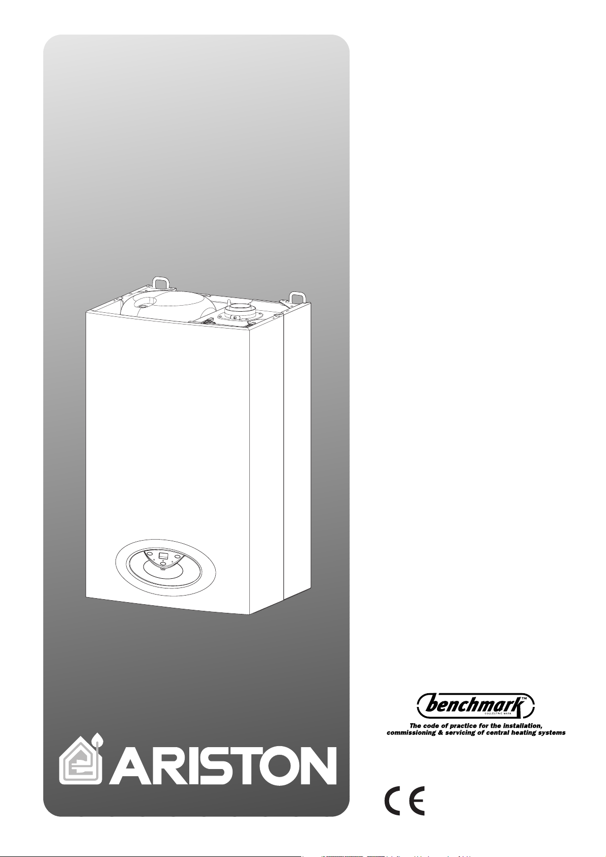
GENUS HE 35 Plus
BFFi
Installation and
Servicing
Instructions
Type C Boilers
G.C.N: 47-116-57 (35 kW)
LEAVE THESE
INSTRUCTIONS WITH THE
END-USER
GENUS
HE 35
Plus
Country of destination
GB
IE
Page 2

2
1. General Information
2. Control Panel
3. How to Use
4. Anti-Frost Device
5. Maintenance
6. Trouble Shooting
7. Filling Instructions
8. Time Clock
8.1 Setting the Mechanical Clock
8.2 Setting the Digital Clock
9. General Information for the Installer
9.1 Overall View
10. Installation
10.1 Delivery
10.2 Reference Standards
10.3 Siting the Appliance
10.4 Clearances
10.5 Overall View
10.6 Mounting the Appliance
10.7 Electrical Connection
10.8 Gas Connection
10.9 Water Connections
11. Connecting the Flue
11.1 Fitting the Coaxial Flue (Ø 60/100 mm Horizontal)
11.2 Fitting the Coaxial Flue (Ø 60/100 mm Vertical)
11.3 Fitting the 5” Flue (Ø 80/125 mm - Vertical)
11.4 Fitting the Twin Pipe (Ø 80/80 mm)
12. Electrical Connections
13.
Electrical System Diagrams
14. Water Circuit Diagrams
15. Commissioning
15.1 Initial Preparation
15.2 Completion
15.3 Removal and Fitting of the Case - Servicing
15.4 Pressurisation
15.5 Commissioning
15.6 Settings
15.7 Operating Faults
TABLE OF CONTENTS
16. Gas Convertion
17. Maintenance
18. Servicing Instructions
18.1 Replacement of Parts
18.2 To Gain General Access
18.2.1 Removing the front panel
18.2.2 Removing the control panel
18.3 Access to the Control System
18.3.1 Removing the main PCB
18.3.2 Removing the display PCB
18.3.3 Removing the fuses
18.3.4 Removing the time clock
18.4 Access to the Combustion Chamber
18.4.1 Removing the combustion chamber front panel
18.4.2 Removing the air gas assembly
18.4.3 Removing the burner
18.4.4 Removing the detection electrode
18.4.5 Removing the ignition electrode
18.4.6 Removing the fan
18.4.7 Removing the gas valve
18.4.8 Removing the heat exchanger
18.4.9 Removing the spark generator
18.5 Access to the Water Circuit
18.5.1 Drain down
18.5.2 Removing the 3 way valve
18.5.3 Removing the heating return filter
18.5.4 Removing the by-pass
18.5.5 Removing the pressure relief valve (3 bar)
18.5.6 Removing the pressure relief valve (7 bar)
18.5.7 Removing the temperature & pressure relief
valve (7 bar)
18.5.8 Removing & cleaning the condensate trap
18.5.9 Removing the pressure gauge
18.5.10 Removing the pump
18.5.11 Removing the heating expansion vessel
18.5.12 Removing the DHW expansion vessel
18.5.13 Removing the overheat thermostat
18.5.14 Removing the temperature sensors (N.T.C’s)
18.5.15 Removing the tank temperature sensor
18.5.16 Removing the water pressure gauge
18.5.17 Removing the flow switch
18.5.18 Removing the DHW temperature sensor
18.5.19 Removing the non return valve
18.5.20 Removing the plate heat exchanger
18.5.21 Removing the tank
19. Fault Finding Guide
20. Short Spares List
21. Technical Information
Page 3

3
These instructions are suitable for the GENUS HE 35 Plus boilers :
Do not forget the Log Book!
MTS supports Benchmark, the heating industry code to ensure the correct installation, commissioning and servicing of
domestic central heating systems.
To The Householder
Make sure you have a completed Log Book for your boiler. This provides a record of the commissioning of your boiler.
It contains important information about your particular installation that may be required by service engineers. The Log Book will
also provide contact details for the installer should you need guidance in the use of this appliance or if there are any problems.
As with your car, your boiler will work more reliably and efficiently if regularly serviced. We recommend an annual service
check. The service history of the appliance will be recorded on the Log Book.
In the unlikely event of any problems with your boiler or system you should first contact your installer. If your installer cannot
resolve the problem he should telephone our national service helpline.
A charge may be made if MTS Service is called out to resolve a non-product related fault.
Your statutory rights are not affected.
CUSTOMER CARE
MTS, as a leading manufacturer of domestic and commercial water heating appliances is committed to providing high quality
products and a high quality after sales service.
Advice on installation or servicing can also be obtained by contacting the MTS Technical and Customer Service Departments
at High Wycombe.
TECHNICAL DEPARTMENT CUSTOMER SERVICE DEPARTMENT
Tel: 0870 241 8180 Tel: 0870 600 9888
Fax: 01494 459775 Fax: 01494 459775
GUARANTEE
The manufacturer’s guarantee is for 2 years from the date of purchase. The guarantee is invalidated if the appliance is not
installed in accordance with the recommendations made herein or in a manner not approved by the manufacturer. To assist us
in providing you with an efficient after sales service, please return the guarantee registration card enclosed with the boiler
without delay.
CAUTION
In the United Kingdom, installation, start-up, adjustments and maintenance, must be performed by a competent person only, in
accordance with the current Gas Safety (Installation & Use) Regulations and the instructions provided.
In the Republic of Ireland, the installation and initial start up of the appliance must be carried out by a Competent Person in
accordance with the current edition of I.S.813 “Domestic Gas Installations”, the current Buidling Regulations, reference should
also be made to the current ETCI rules for electrical installation.
All CORGI registered installers carry a CORGI ID card, and have a registration number. Both should be recorded in
your boiler Log Book. You can check your installer is CORGI registered by calling CORGI direct on:- (01256) 372300.
Improper installation may cause damage or injury to individuals, animals and personal property for which the manufacturer will
not be held liable. To ensure efficient and safe operation it is recommended that the boiler is serviced annually by a competent
person.
If it is known that a fault exists on the appliance, it must not be used until the fault has been corrected by a competent person.
To The Installer
As part of the commissioning of this appliance it is vital that the Log Book is completed and given to the Householder. Please
ensure that your customer is aware of the importance of keeping the Log Book safe as a record of the installation and the
appliance service history.
Please ensure that your customer is aware of the correct operation of the system, boiler and controls.
MTS recommend the use of protective clothing, when installing and working on the appliance i.e. gloves.
This instruction booklet is especially designed for appliances installed in the UK and the Republic of Ireland
1. GENERAL INFORMATION
Page 4
4
2. CONTROL PANEL
* Warning the flue analysis mode must only be selected by a qualified service engineer.
1
2
3
4
5
6
7
8
9
10
11
12
13
14
15
16
17
18
19
20
21
22
23
24
9
6
12
36
37
30
26
32
29
33
34
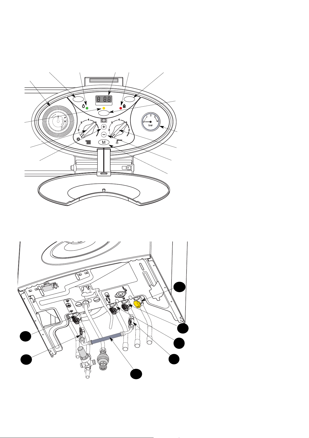
Control panel (Fig. 2.1)
26. - On/off push button
27. - Reset push button
28. - domestic hot water function and COMFORT tank on/off button
29. - burner operation green indicator light
30. - red indicator lock-out light
31. - yellow indicator - Comfort button
32. - Central Heating control knob
stop/mini/maxi
33. - DHW control knob /mini/maxi
34. - Increasing button +
35. - Reducing button -
36. - Menu button
37. - Pressure gauge
46. - Time clock
48. - Display
35
27
28
31
48
46
FIG. 2.1
USER INSTRUCTIONS
Connecting bracket
Taps shown in Open position (Fig. 2.2)
39 : Gas service tap
40 : Water service tap
41 : Central heating flow isolating valve
42 : Central heating return isolating valve
43 & 44: Filling taps
45 : Filling loop
Fig. 2.2
41
42
43
44
45
39
40
ON/OFF
1
24
2
23
3
22
4
12
5
6
7
9
8
9
10
21
20
I
19
18
17
16
6
15
11
14
12
13
COMFORT
RESET
Page 5
5
3. HOW TO USE
Switching on
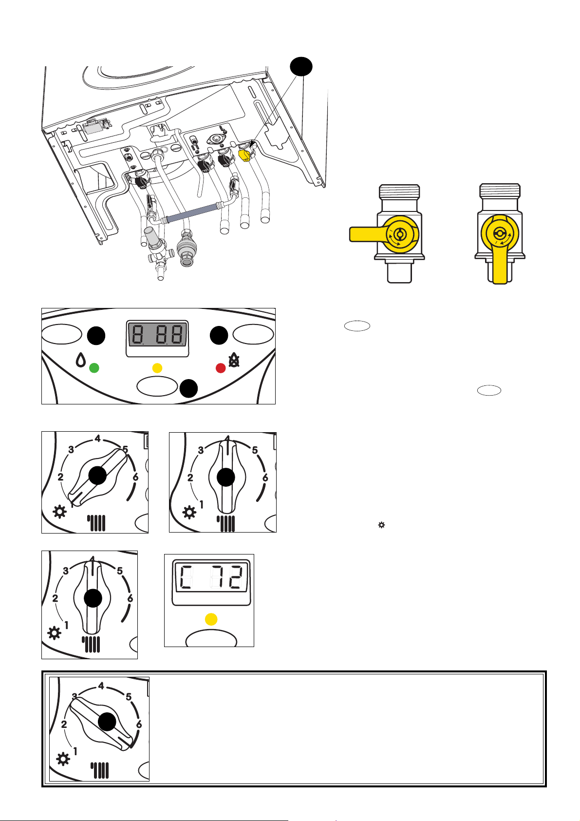
1. Check that the pressure in heating system is
adequate, i.e. the pressure gauge 37 shows 1
bar minimum and 1.5 bar maximum.
2. Check that the gas service tap 39 (Fig. 3.1) is
opened (Figs. 3.2 and 3.3) and that the mains
power is on, On/Off push button 26 Power
ON.
The boiler is now ready to use.
Note : If the boiler has been turned off for some
time, the presence of air in the gas pipe
may result in a lockout.
FIG. 3.2
FIG. 3.3
GAS COCK CLOSED
GAS COCK OPEN
FIG. 3.1
26
27
30
32
32
32
39
Ignition procedure
Press the button 26, the electronic control unit will ignite the
burner without any manual intervention (only when there is a
demand for Domestic hot water or heating). If the burner does not
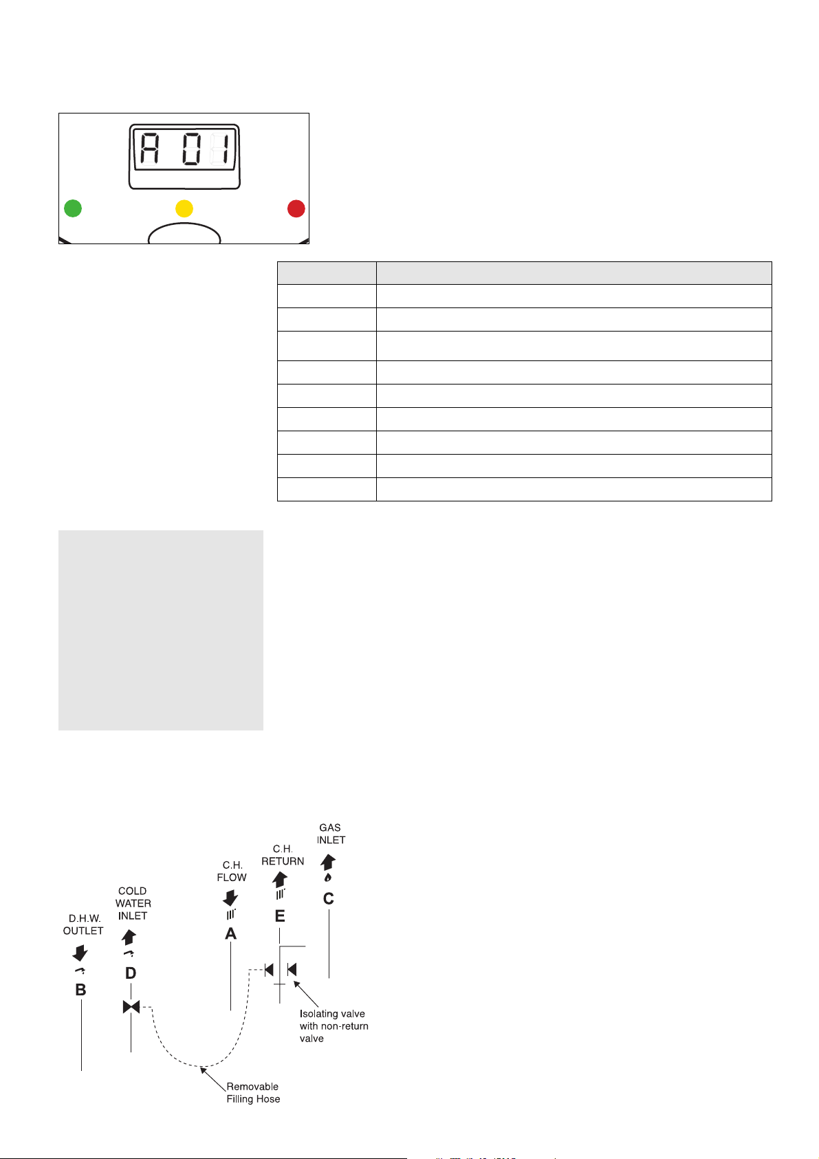
ignite within the safety period, the screen will display error code A01
and the warning light 30 will come on.
To reinitialise the ignition system, press the button 27.
If ignition fails again, verify that the gas tap is open before calling a
qualified technician.
RESET
ON/OFF
Summer and winter operation
The boiler produces hot water for heating and Domestic hot water.
Winter operation means the production of hot water for heating and
the production of Domestic hot water. Summer operation means the
production of Domestic hot water only. The boiler control panel
allows selection of winter or summer operation.
Keep the knob 32 in the position to select summer operation. To
select winter operation, turn the knob 32 to a position between the
minimum value and the maximum value.
Heating temperature control
To adjust the heating water temperature, use the knob 32, position
the pointer between the minimum and maximum values; the
temperature obtained can vary between 42°C and 82°C or 25°C and
75°C.
The heating command is activated by a mechanical programmer, or
the room thermostat or a remote unit.
Installation with regulation by external temperature
(Only activated if the external sensor is installed)
In this case, by turning the knob 32, it is possible to change the heating outlet temperature and
therefore the ambient temperature of your home. When the knob is turned, the display indicates
P6 and the heating outlet temperature can be varied by - 20 °C to 20 °C.
However, the boiler can be controlled by the timeswitch, a Clima Manager remote control or a
room thermostat.
As soon as the desired temperature is reached, the burner is switched off and the circulation
pump stops or goes into post-circulation mode.
32
ON/OFF
COMFORT
RESET
+
+
COMFORT
Page 6
6
The boiler is fitted with a device, which in the event that the water
temperature falls below 8
o
C the pump activates and runs until a
temperature of 18
o
C is attained. In the event that the water
temperature falls below 3
o
C, the diverter valve switches to Domestic
Hot Water and the burner fires on minimum power until a temperature
of 33
o
C is attained.s
This device is only activated when the boiler is operating perfectly and
- the system pressure is sufficient;
- the boiler is powered electrically;
- gas is available.
Schedule an annual maintenance check-up for the boiler with a CORGI
registered Service Engineeer in the UK and with a competent person
as described in I.S.813 for IE.
Correct maintenance always results in savings in the cost of running
the system.
4. ANTI-FROST DEVICE
5. MAINTENANCE
33
32
R
Afficheur gauche
Afficheur droit
28
Regulation of Domestic hot water
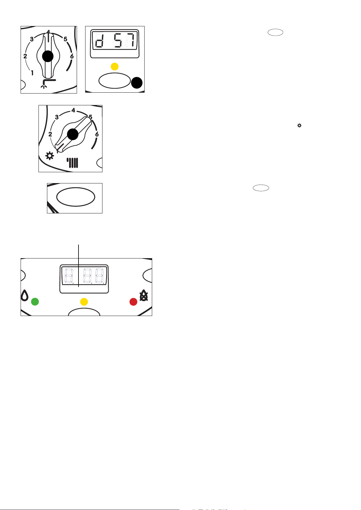
To obtain Domestic hot water, press the button COMFORT 28
(yellow LED comes on)
To adjust the Domestic hot water temperature in winter or summer
operation, use the knob 33. It is possible to determine the temperature of
water stored in the tank between 40°C and 70°C.
COMFORT
Interruption of heating
To interrupt heating, turn the knob 32 to the sun position .
The boiler will continue to operate in the summer position to provide
Domestic hot water only.
Switch-off procedure
To switch the boiler off, press the button 26. Close the gas tap
located under the boiler and move the boiler external power supply switch
to the OFF position.
ON/OFF
Display: display of current operations
During operation of the boiler, in other words when it is performing its
normal functions, the left side of the display shows a series of characters
referring to the operations, as indicated below:
0
No heating command
C
Heating
c
pump in post-circulation mode for heating
d
Domestic hot water
h
Pump in post-circulation mode for Domestic hot water
b
Tank reheating
On the right, the display shows (2 characters):
- in heating mode: heating installation output temperature
- in Domestic hot water distribution mode: drawing-off temperature.
- in tank reheating mode: tank temperature or drawing-off temperature.
ON/OFF
COMFORT
Page 7
7
AFFICHEUR CAUSE
A01
Three ignition attempts
A03
The output temperature exceeds 105°C during operation
A07
Too many flame separations over a period during operation
A17
Input water circulation fault
A18
No water circulation
A33
Fan problem
A97
Electronic control problem
A98
Electronic control problem
A99
Electronic control problem
6. TROUBLE SHOOTING
7. FILLING INSTRUCTIONS
A method for initially filling the system and replacing lost water
during servicing and initial filling (in accordance with current Water
Regulations), is provided as an integral part of the connection kit
(see Fig. 3.1).
To fill the system and replace lost water it is necessary to proceed
as follows:
- Switch off the power to the boiler;
- Ensure that the flexible hose is connected to both the cold
water inlet connection and the C.H. flow connection;
- Open the black lever on the valve for the C.H. flow connection
and slowly open the black handle on the valve for the cold water
inlet until water is heard passing through the valves;
- Once the pressure gauge 37 (Fig. 2.1) reads between 1 and
1.5 bar close the levers on both the cold water connection and the
C.H. flow connection
- Switch the power to the boiler back on.
N
OTE: THE FLEXIBLE HOSE MUST BE REMOVED ONCE THE SYSTEM HAS
BEEN FILLED
.
FIG. 7.1
CONDITIONS FOR STOPPAGE OF THE BOILER
This boiler is fitted with safety devices which are activated in certain situations
and cause the boiler to stop operating.
There are two types of stoppage:
- Operating failure (A)
- Safety stop (E)
OPERATING STOPPAGE "A"
This type of stoppage is displayed in the form of a number preceded by a
letter (A) as shown in the following table.
To clear this type of stoppage, press the reset button (Reset).
In the table, each error code is associated with the problem causing it to
appear.
In the case of error
A 02
, before
calling a qualified technician, check
the pressure gauge to see if the
water pressure in the appliance is 1
bar. If necessary, restore the
pressure using the filling valve
located under the boiler and perform
an ON/OFF operation by pressing
the button. If the pressure falls
frequently in the appliance, have a
plumber check for water leaks.
N.B. Warning! The boiler is always
connected to an electrical supply.
IMPORTANT
If this type of failure occurs too often,
call an approved after sales technical
service. For safety reasons, the
boiler will only allow 5 reignition
attempts in 15 minutes (pressing of
the RESET button). After the fifth
attempt, the boiler goes into safety
shutdown mode E 99.
This is therefore not a problem in the
case of sporadic or isolated
stoppages.
SAFETY SHUTDOWN “E”
In the event of a safety shutdown, indicated by display of the letter E followed by a
number, there is no need to take action. The boiler will automatically attempt to reset and
restart. If this does not occur, call a qualified technician. Switch off the boiler as described
in the previous paragraph, close the gas tap and move the external electrical supply
switch to the OFF position.
Antilocking of pump and three-way valve
To prevent locking of the components, the appliance performs a self-test every 24 hours:
the pump starts up for 3 seconds and the diverting valve is operated.
Page 8
8
8. TIME CLOCK
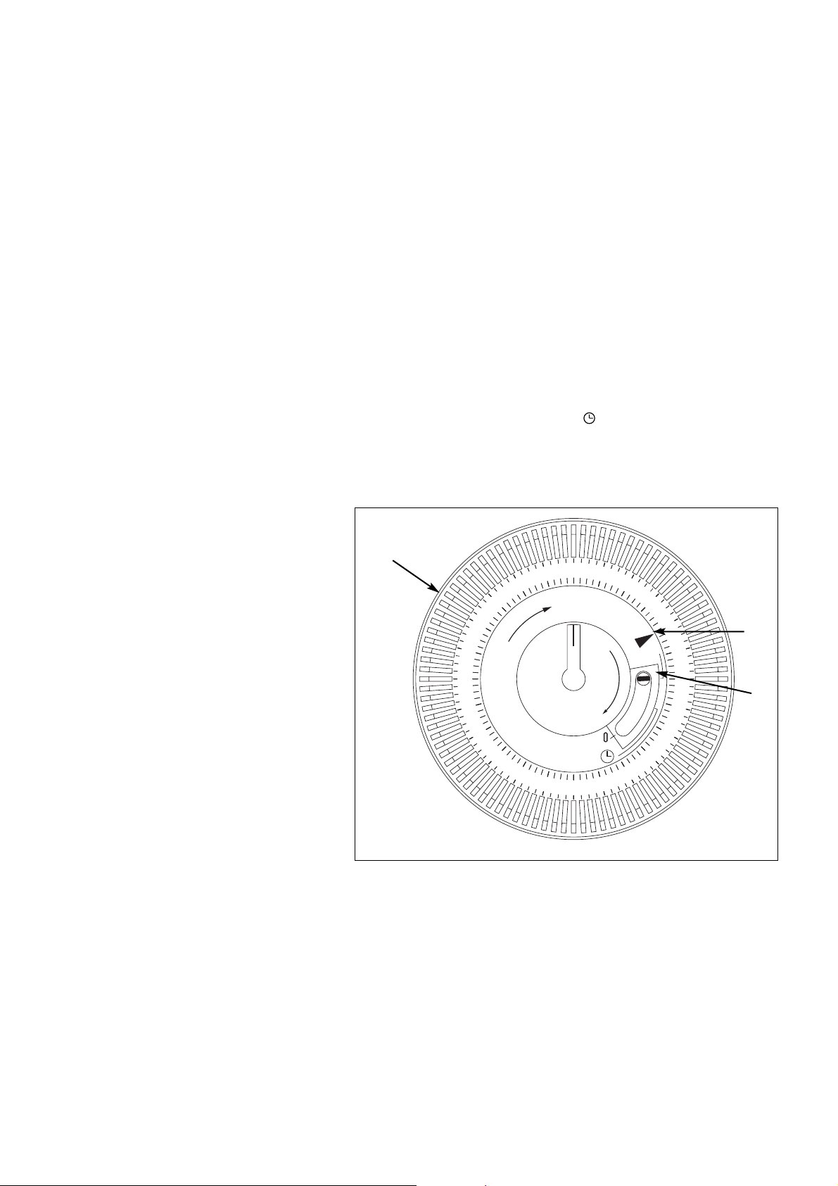
1. General layout
The mechanical clock covers a 24 hour period. Each tappet
represents 15 minutes A (Fig 8.1). An override switch is located on
the clock B (Fig 8.1).
2. To set the time
To set the time of day, grasp the outer edge of the dial and turn
slowly clockwise until the correct time is lined up with the arrow C
(Fig. 8.1).
3. To Set the "On" and "Off" times
The clock uses a 24hours system. e.g. 8 = 8.00 am and
18 = 6.00 pm "ON" periods are set by sliding all tappets between
the "ON" time and the "OFF" time to the outer edge of the dial.The
tappets remaining at the centre of the dial are the "OFF" periods.
4. For operation
Put the selector switch B to the symbol to control the central
heating by the clock. Put the switch B to «I» to select permanent
operation or to «0» to turn the central heating off permanently.
1
2
3
4
5
6
7
8
9
10
11
12
13
14
15
16
17
18
19
20
21
22
23
24
9
6
12
A
C
B
8.1 Setting the Mechanical Clock
FIG. 8.1
1
12
6
13
24
14
23
15
22
16
21
20
I
19
18
17
2
3
4
5
6
7
9
8
9
10
11
12
Page 9
9
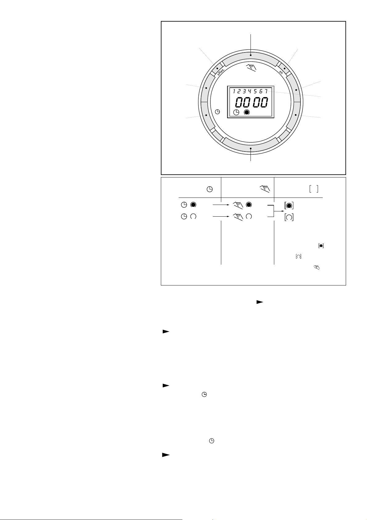
Operating the time switch
The step marked with the symbol “ ” are necessary to carry out a
switching program.
Preparing for Operation
Activate the “Res” switch (=RESET) to reset the time switch to its
default setting (activate using a pencil or similar pointed instrument).
Do this:
- every time you wish to “reset” the time switch
- to erase all switching times and the current time of day.
After approximately two seconds the following display appears:
Enter current time and weekday
- Keep the “ ” key pressed down
During the summer time period press the +/- 1h key once.
Enter the hour using the “h” key
Enter the minutes using the “m” key
Enter the day using the “Day” key
1 = “Monday”..............7 = Sunday
- Release the “ ” key.
Entering the switching times
You have 20 memory Iocations available. Each switching time takes
up one memory location.
Keep pressing the “Prog” key until a free memory location is shown in
the display “– –:– –”.
8.2 Setting the Digital Clock
Reset
Manual switch
Summer and
winter time
setting
Enter
switching
times
Imput
time
Automatic Manual Continuous
Operation Operation Operation
= ON = ON = Continuously ON
= OFF = OFF = Continuously OFF
The switching If the current You can only
times corres- switching mode is return to automatic
pond to the changed manually, mode from the
program the next switching continuously-ON
entered. time will be and continuously-
carried out auto- OFF switching
matically again modes by
according to the pressing the " "
entered switching key.
program.
.
g
o
r
P
Day
Enter
weekday/s
h
m
Enter
the hours
Week-
days
flash
Enter
minutes
Page 10

10
Programme ON or OFF with the “ ” key:
“ ”= OFF; “ ”= ON
Enter the hour using “h”
Enter the minutes using “m”
If a switching command is to be carried out every day (1 2 3 4 5 6
7) then store using the “ ” key, otherwise select the day(s) it is to
be carried out by using the “Day” key.
When the day seIection is left bIank, the programmed switching
instruction operates at the same time every day
1 2 3 4 5 6 = Monday – Saturday
1 2 3 4 5 = Monday – Friday
6 7 =Saturday – Sunday
Selection of single days: 1 = Mon. .............. 2 =Tues.
Save the switching time with the “ ” key.
The time switch enters the automatic operating mode and displays
the current time of day.
Begin any further entry of a switching time with the “Prog” switch. If
your entry is incomplete, the segments not yet selected will blink in
the display. After programming is completed, and you return the
time clock to the current time display with the “ ” key, the time
clock will not activate any switching instruction required for the
current time. You may need to manually select the desired
switching state with the “ ” key. Thereafter, as the unit
encounters further switching instructions in the memory in real time,
it will correctly activate all subsequent switching instructions.
Manual Override Switch “ ”
With the “ ” you can change the current setting at any time. The
switching program already entered is not altered.
Reading the programmed switching times
Pressing the “Prog” key displays the programmed switching times until
the first free memory location appears in the display “– – : – –”.
If you now press the “Prog” key once again, the number of free memory
Iocations will be displayed, e.g. “18”. If all memory locations are
occupied, the display “00” appears.
Changing the programmed switching times
Press the “Prog” key repeatedly until the switching time you want to
change is displayed. You can now enter the new data. See point
“Entering the switching times”.
Notes on storing switching times:
If you end your entry of the switching times by pressing the “Prog” key,
then the switching time you have entered will be stored and the next
memory location displayed.
In addition, a complete switching command is stored automatically
after around 90 seconds provided no other key is pressed. The time
switch then enters the automatic operating mode and displays the
current time again.
Deleting individual switching times
Press the “Prog” key repeatedly until the switching time you wish to
delete is shown in the display. Then set to “– –” using the “h” or “m” key
and keep the “ ” key pressed down for around 3 seconds. The
switching time is now erased and the current time is displayed.
AM / PM time display
If you press the “+/-1h” and “h” keys at the same time, the time display
switches into the AM/PM mode.
Page 11

11
Read the instructions and recommendations in these Installation and Servicing Instructions carefully to ensure proper installation,
use and maintenance of the appliance.
Keep this manual in a safe place. You may need it for your own reference while Servicing Technicians or your installer may need
to consult it in the future.
This is a combined appliance for the production of central heating (C.H.) and domestic hot water (D.H.W.).
This appliance must be used only for the purpose for which it is designed.
The manufacturer declines all liability for damage caused by improper or negligent use.
No asbestos or other hazardous materials have been used in the fabrication of this product.
Before connecting the appliance, check that the information shown on the data plate and the Technical Information (Section 21)
comply with the electric, water and gas mains of the property. You will find the data plate on the reverse of the control panel.
Do not install this appliance in a damp environment or close to equipment which spray water or other liquids.
Do not place objects on the appliance.
Do not allow children or inexperienced persons to use the appliance without supervision.
If you smell gas in the room, do not turn on or off light switches, use the telephone or any other object which might cause
sparks.
Open doors and windows immediately to ventilate the room.
Shut the gas mains tap (at or adjacent to the gas meter) or the valve of the gas cylinder and call your Gas Supplier immediately.
If you are going away for a long period of time, remember to shut the mains gas tap or the gas cylinder valve.
Always disconnect the appliance either by unplugging it from the mains or turning off the mains switch before cleaning the
appliance or carrying out maintenance.
In the case of faults or failure, switch off the appliance and turn off the gas tap. Do not tamper with the appliance.
For repairs, call your local Authorised Servicing Agent and request the use of original spare parts. For in-guarantee repairs
contact MTS (GB) Limited.
Check the following at least once a year:
1 - Check the seal of water connections, replacing the gaskets if necessary.
2 - Check the seal of the gas connections, replacing the gaskets if necessary.
3 - Check the general condition of the appliance and of the combustion chamber visually.
4 - Visual check of the combustion: clean burners if necessary.
5 - With reference to point 3, dismantle and clean the combustion chamber if necessary.
6 - With reference to point 4, dismantle and clean the injectors if necessary.
7 - Visual check of the primary heat exchanger:
- check for overheating of the exchangers fins;
- clean the exhaust side of the exchanger and fan if necessary.
8 - Regulate the gas pressure, ignition pressure, partial flame, maximum flame.
9 - Check proper operation of the heating safety system:
- maximum safety temperature;
- maximum safety pressure.
10 - Check the proper operation of the gas safety system:
- gas or flame safety device;
- gas valve safety device.
11 - Check that the electrical connections have been made in compliance wit h the instructions shown in the Installation
Instructions.
12 - Check the efficiency of the hot water supply (flow and temperature).
13 - Check pressure in the Domestic Expansion Vessel and top up as necessary.
14 - Check manually by turning the test knob the Temperature & Pressure Relief Valve.
15 - Check manually by turning the test knob the Expansion Relief Valve.
16 - Check discharge pipes from both the central heating and domestic hot water for obstructions.
17 - Check general operation of the appliance.
18 - Check the exhaust system for the combustion products.
19 - Check all unvented domestic hot water controls and systems
NOTE: These checks are not exhaustive
9. GENERAL INFORMATION FOR THE INSTALLER
INSTALLER INSTRUCTIONS
Page 12
12
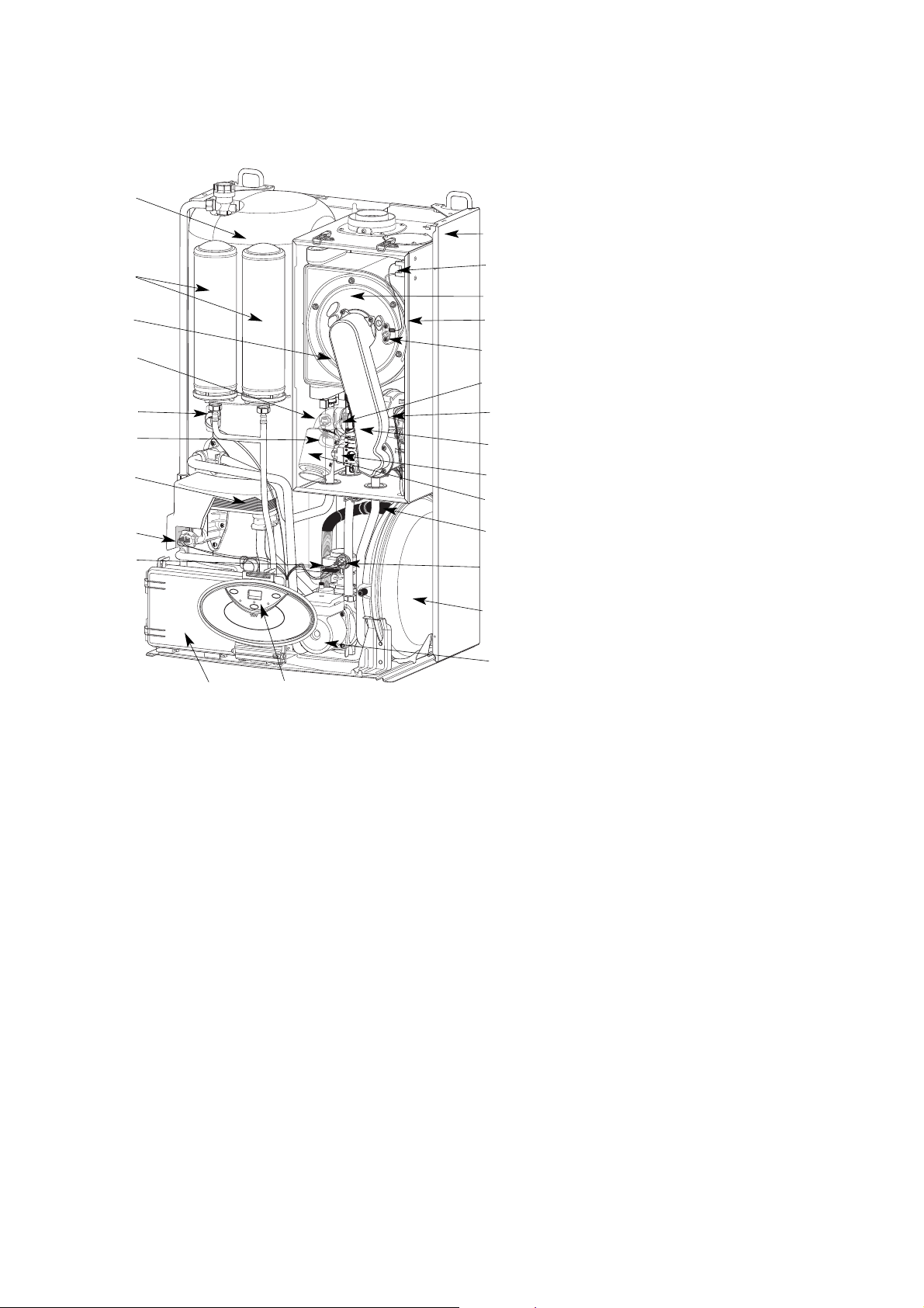
9.1 OVERALL VIEW
1
2
3
4
5
6
8
10
11
13
14
7
15
16
18
12
19
17
9
21
20
22
23
24
25
FIG. 9.1
1. - sheet steel casing
2. - pressurised expansion tank
3.- sealed casing
4. - burner/exchanger assembly
5. - 24 V fan
6. - air/gas connection assembly
7. - ignition electrodes
8. - flame detection electrode
9. - stainless steel Domestic hot water tank
10. - circulation pump
11.- electronic control unit
12. - ignition transformer
13.- overheat cut-off
14. - gas valve
15. - tank sensor
16. - heating outlet sensor
17. - heating return sensor
18.- distributor valve
19. - stainless steel plate Domestic hot water
exchanger
20. - Domestic hot water flow rate controller
21. - Domestic hot water sensor
22. - silencer
23. - siphon
24. - Domestic hot water expansion cylinder
25. - pressure switch
Page 13

13
The technical information and instructions provided herein below are
intended for the installer / Servicing Technician so that the unit may be
installed and serviced correctly and safely.
There will be two items:
1 - The fully assembled boiler
2 - A separately boxed connection kit
WATER REGULATIONS
In GB it is necessary to comply with the Water Supply (Water Fittings)
Regulations 1999, for Scotland, The Water Bylaws 2000, Scotland. The
Genus 30 Plus is an approved product under the Water Regulations.
To comply with the Water Regulations, you attention is drawn to The Water
Regulations guide published by the Water Regulations Advisory Scheme
(WRAS) gives full details of the requirements.
In IE, the requirements given in the current edition of I.S.813 and the
current Building Regulations must be followed.
BUILDING REGULATIONS
These are a statutory document and take priority over all other regulations
and recommendations. The installation of an unvented hot water storage
cylinder is classified as a "Controlled Service" and Regulation G3 applies.
To meet the requirements of the Regulation, installation of an unvented
system should be undertaken by a "competent installer".
All installations of unvented hot water storage systems having a capacity of
more than 15 litres should be notified to the relevant Local Authority by
means of Building Notice or by the submission of full plans. It is important
to note that it is a criminal offence to install an unvented hot water storage
system without notifying the Local Authority.
The installation of this appliance must be in accordance with the
relevant requirements of the Local Building Regulations, the current
I.E.E. Wiring Regulations, the bylaws of the local water authority, in
Scotland, in accordance with the Building Standards (Scotland)
Regulation and Health and Safety document No. 635 “Electricity at work
regulations 1989” and in the Republic of Ireland with the current edition
of I.S. 813, the Local Building Regulations (IE).
C.O.S.H.H.
Materials used in the manufacture of this appliance are non-hazardous
and no special precautions are required when servicing.
Installation should also comply with the following British Standard
Codes of Practice:
10. INSTALLATION
10.2 Reference Standards
10.1 Delivery
BS 7593 Treatment of water in domestic hot water
central heating systems
BS 5546 Installation of hot water supplies for
domestic purposes
BS 5440-1 Flues
BS 5440-2 Air supply
BS 5449 Forced circulation hot water systems
BS 6798 Installation of gas fired hot water boilers
of rated input not exceeding 60kW
BS 6891 Installation of low pressure gas pipe up to
28mm
BS 7671 IEE wiring regulations
BS 7074 Specification for expansion vessels
BS 5482 Installation of L.P.G.
Page 14

10.3 Siting the Appliance
14
and in the Republic of Ireland in accordance with the following
Codes of Practice:
WARNING!!
The addition of anything that may interfere with the normal
operation of the appliance without express written permission of
the manufacturer or his agent could invalidate the warranty. In GB
this could also infringe the GAS SAFETY(Installation and Use)
REGULATIONS.
In the Republic of Ireland the installation and initial start up of the
appliance must be carried out by a Competent Person in
accordance with the current edition of I.S.813 “Domestic Gas
Installations”, the current Building Regulations, reference should
also be made to the current ETCI rules for electrical installation.
The appliance may be installed in any room or indoor area,
although particular attention is drawn to the requirements of the
current I.E.E. Wiring Regulations, in Scotland, the electrical
provisions of the Building Regulations applicable in Scotland, and
in the Republic of Ireland, the current edition of I.S.813, with
respect to the installation of the combined appliance in a room
containing a bath or shower. The location of the boiler in a room
containing a bath or shower should only be considered if there is
no alternative.
Where a room-sealed appliance is installed in a room
containing a bath or shower reference should be made to the
relevant requirements.
In GB this is the current I..E.E. WIRING REGULATIONS and
BUILDING REGULATIONS. In IE reference should be made to
the current edition of I.S.813 and the current ETCI rules.
If the boiler is to be sited into a timber framed building, reference
must be made to the current edition of the Institution of Gas
Engineers Publication IGE/UP/7 (Gas Installations in Timber
Framed Housing).
The location must permit adequate space for servicing and air
circulation around the appliance as indicated in Section 10.4.
The location must permit the provision of an adequate flue and
termination.
For unusual locations special procedures may be necessary.
BS 6798-1987 gives detailed guidance on this aspect.
A compartment used to enclose the appliance must be designed
specifically for this purpose. No specific ventilation requirements
are needed for the installation within a cupboard.
This appliance is not suitable for outdoor installation.
I.S. 813 Domestic Gas Installations
The following BS Standards give valuable information;
BS 5546 Installation of hot water supplies for
domestic purposes
BS 5449 Forced circulation hot water systems
BS 7074 Specification for expansion vessels
BS 7593 Treatment of water in domestic hot water
central heating systems
Page 15
15
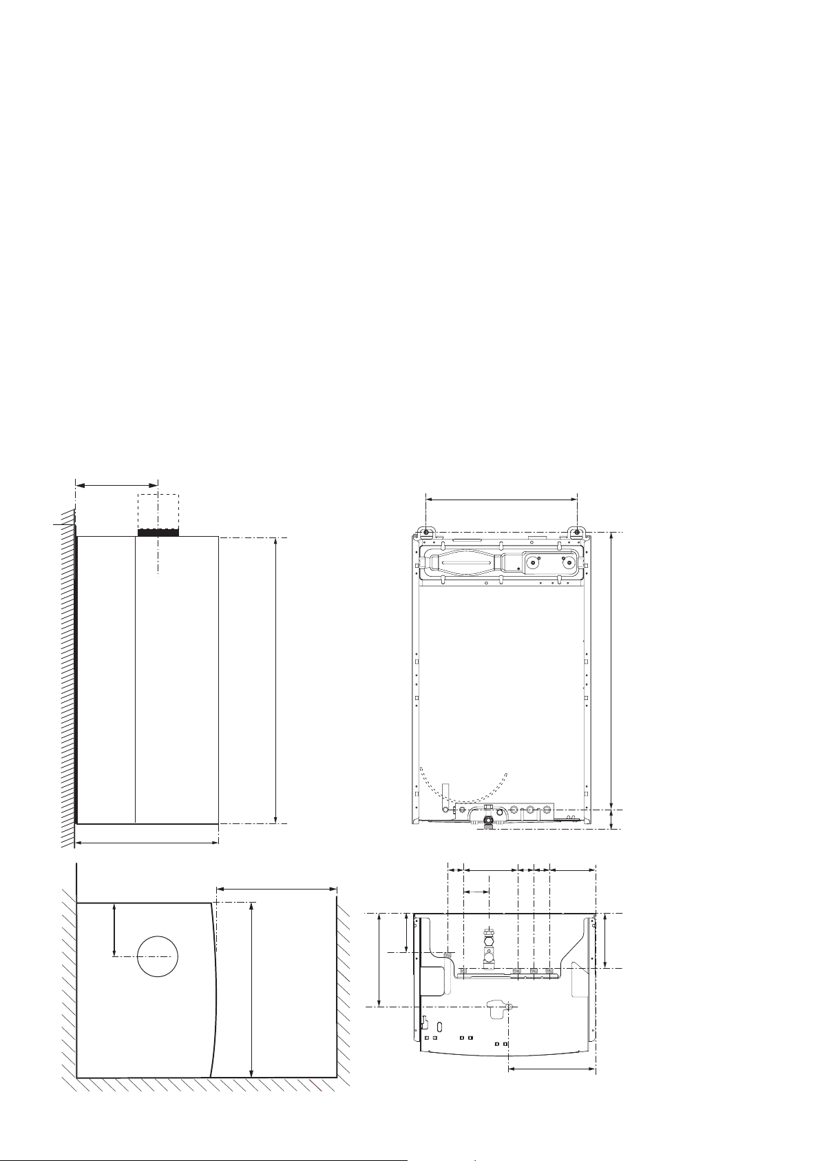
10.5 Overall Dimensions
FIG. 10.1
The type C appliances (in which the combustion circuit,
air vent intake and combustion chamber are air-tight
with respect to the room in which the appliance is
installed) can be installed in any type of room.
Secondary ventilation is not required with this boiler. The
boiler must be installed on a solid, non-combustible,
permanent wall to prevent access from the rear.
In order to allow for access to the interior of the boiler for
maintenance purposes, the boiler must be fitted with a
clearance of 450 mm in front 400 mm below the boiler and
200mm above the boiler, and installed in compliance with the
clearance requirements indicated in Fig. 10.1.
Legend:
39 = Gas service tap
40 = Heating return
41 = Heating flow
42 = Water service tap
43 = Tank hot water flow
38 = Water tank
discharge valve
44 = Central heating
discharge valve
10.4 Clearances
195
500
180
470
950
450mm minimum for
servicing purposes
595
317
135
54
43
42
54 145
172 54
80
38
41
44
40
39
280
925
57
188
Page 16
16
After removing the boiler from its packaging, remove the
template from the separate box containing the connection
kit. N
OTE: Pay particular attention to any test water that
may spill from the appliance.
Place the template in the position the appliance is to be
mounted and after ensuring it is hanging squarely, use it to
drill the holes for the hanging bracket, connection kit and
flue pipe(s) NB: For further information relating to the flue
installation please refer to Section 11 F
LUE CONNECTION. (If
the appliance is to be fitted on a wall of combustible
material, the wall must
be protected by a sheet of fireproof
material).
If the appliance is to be fitted into a timber framed building,
guidance should be sought from the Institute of Gas
Engineers document R
EF: IGE/UP/7.
10.6.1. Drill the wall and plug using those supplied with
the connections kit, position the hanging bracket and
secure with the wall bolts supplied, assembl the
connection kit and secure to the wall. N
OTE: It is highly
recommended that a spirit level be used to position the
appliance to ensure that it is perfectly level.
10.6.2. Position the appliance on the hanging bracket
and connect the connection kit to the boiler connections.
(see also Sections 10.8 Gas Connections, 10.9 Water
Connections & F
IG.10.2).
For safety purposes, have a competent person carefully
check the electrical system in the property, as the
manufacturer will not be held liable for damage caused by
the failure to earth the appliance properly or by anomalies
in the supply of power. Make sure that the residential
electrical system is adequate for the maximum power
absorbed by the unit, which is indicated on the rating plate.
In addition, check that the section of cabling is appropriate
for the power absorbed by the boiler.
The boiler operates with alternating current, as indicated in
the Technical Information table (Section 21), where the
maximum absorbed power is also indicated. Make sure
that the connections for the neutral and live wires
correspond to the indications in the diagram. The
appliance electrical connections are situated on the
reverse of the control panel (see the Servicing Instructions
Section 18 for further information).
Important!
In the event that the power supply cord must be changed,
replace it with one with the same specifications. Make the
connections to the terminal board located within the control
panel, as follows:
- The yellow-green wire should be connected to the
terminal marked with the earth symbol; make sure to reuse the ferrule mounted on the other supply cord;
- The blue wire should be connected to the terminal
marked “N”;
- The brown wire should be connected to the terminal
marked “L”.
Note: The diagrams for the electrical system are indicated
in Section 13.
FIG. 10.3
10.7 Electrical Connection
10.6 Mounting the Appliance
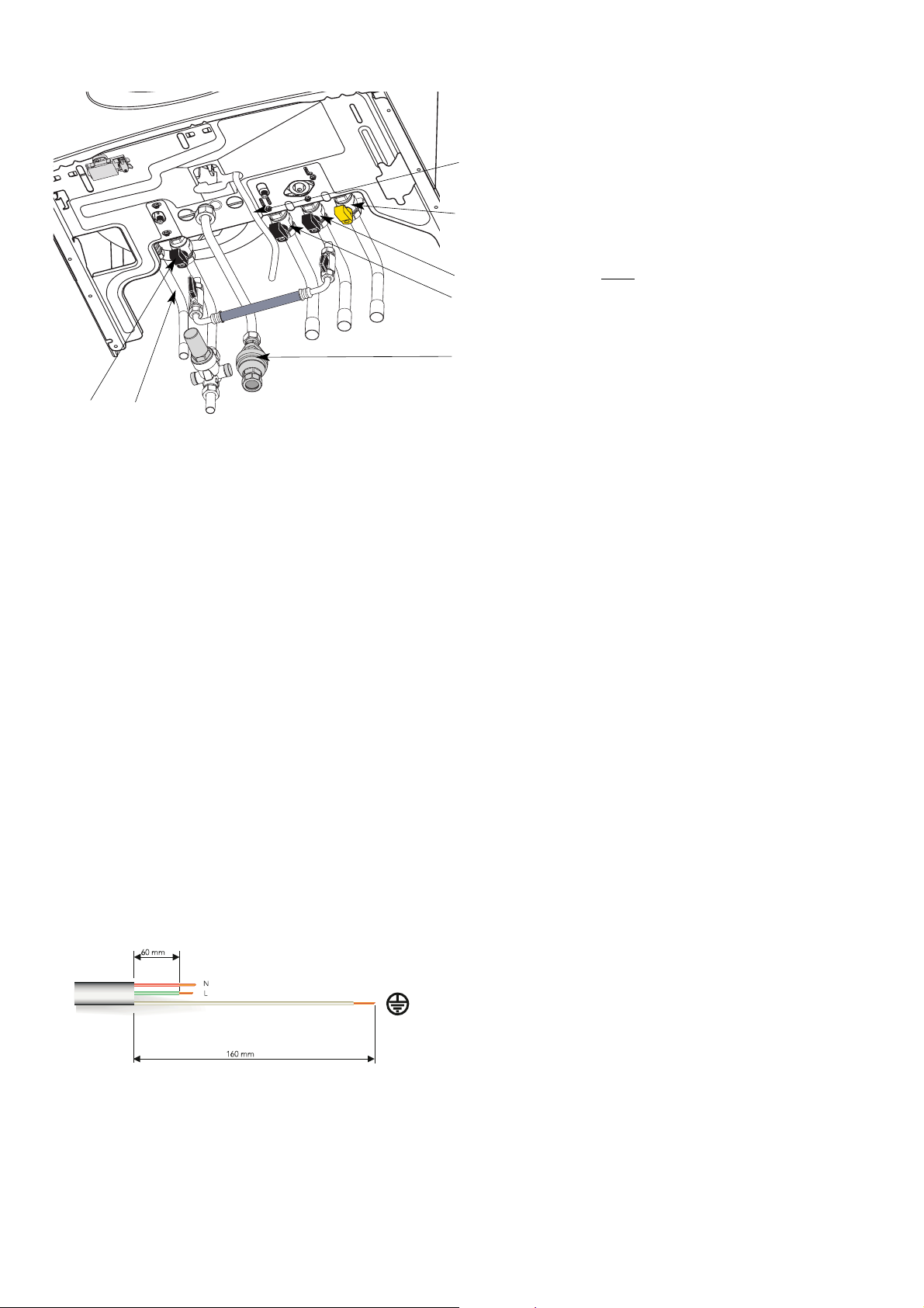
Legend:
39 = Gas service tap
40 = Heating return
41 = Heating flow
42 = Water service tap
43 = Tank hot water flow
38 = Water tank valve
44 = Heating valve
FIG. 10.2
39
40
41
38
44
42
43
Page 17

17
10.8 Gas Connection
Warning, this appliance must be earthed.
External wiring must be correctly earthed, polarised and in
accordance with relevant regulations / rules. In GB this is the
current I.E.E. WIRING REGULATIONS. In IE reference should be
made to the current edition of the ETCI rules. This boiler is supplied
for connection to a 220 - 240 V~ 50 Hz supply.
The supply must be fused at 3 A.
The method of connection to the electricity supply must facilitate
complete electrical isolation of the appliance, by the use of a fused
double pole isolator having a contact separation of at least 3 mm in
all poles or alternatively, by means of a 3 A fused three pin plug
and unswitched shuttered socket outlet both complying with BS
1363.
The point of connection to the Electricity supply must be readily
accessible and adjacent to the appliance unless the appliance is
installed in a bathroom when this must be sited outside the
bathroom.
The local gas region contractor connects the gas meter to the
service pipe.
The gas installation should be in accordance with the relevant
standards. In GB this is BS6891 and in IE this is the current edition
of I.S.813.
The connection the the appliance is a 22 mm copper tail located at
the rear of the gas service cock (Fig. 10.2).
If the gas supply for the boiler serves other appliances ensure that
an adequate supply is available both to the boiler and the other
appliances when they are in use at the same time.
Pipe work must be of an adequate size. Pipes of a smaller size than
the boiler inlet connection should not be used.
Central Heating
Detailed recommendations are given in BS 6798:1987 and BS
5449-1:1990, the following notes are given for general
guidance.
Pipe Work:
Copper tubing to BS EN 1057:1996 is recommended for water
pipes. Jointing should be either with capillary soldered or
compression fittings.
Where possible pipes should have a gradient to ensure air is
carried naturally to air release points and water flows naturally
to drain taps.
The appliance has a built-in automatic air release valve,
however it should be ensured as far as possible that the
appliance heat exchanger is not a natural collecting point for air.
Except where providing useful heat, pipes should be insulated
to prevent heat loss and avoid freezing.
Particular attention should be paid to pipes passing through
ventilated spaces in roofs and under floors.
By-pass:
The appliance includes an automatic by-pass valve, which
protects the main heat exchanger in case of reduced or
interrupted water circulation through the heating system, due to
the closing of thermostatic valves or cock-type valves within the
system.
10.9 Water Connections
Page 18

18
System Design:
This boiler is suitable only for sealed systems.
Drain Cocks:
These must be located in accessible positions to permit the
draining of the whole system. The taps must be at least 15 mm
nominal size an manufactured in accordance with BS 2870:1980.
Safety Valve Discharge (Primary Water):
The discharge should terminate facing downwards on the exterior
of the building in a position where discharging (possibly boiling
water & steam) will not create danger or nuisance, but in an easily
visible position, and not cause damage to electrical components
and wiring.
The discharge must not be over an entrance or a window or any
other type of public access.
Mains Water Feed - Central Heating:
There must be no direct connection to the mains water supply
even through a non-return valve, without the approval of the Local
Water Authority, and must be in accordance with water supply
regulations. Your attention is drawn to, for GB: Guidance G24.2
and recommendation R24.2 of the water regulations guide and for
IE: the current edition of I.S.813.
Filling:
A temporary method for initially filling the system and replacing
lost water during servicing and initial filling (complying to current
water regulations and byelaws) is provided. The flexible hose
must be removed once the system has been filled.
Domestic Hot Water
Storage Discharge Pipe Work
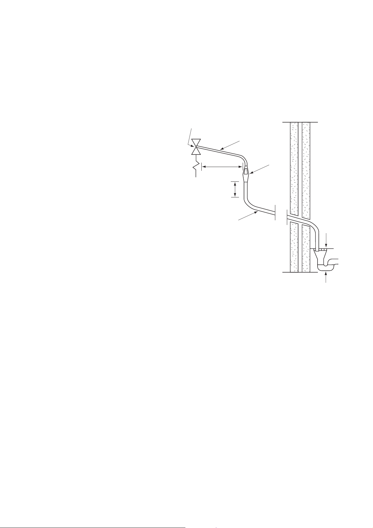
1) The tundish must be installed directly below the discharge outlet
connection of the boiler. The tundish must also be in a position visible
to the occupants, and positioned away from any electrical devices.
The discharge pipe from the tundish should terminate outside in a
safe place where there is no risk to persons in the vicinity of the
discharge and to be of metal.
2) Discharge pipes from the temperature & pressure relief and
expansion relief valve are joined together within the appliance.
3) The pipe diameter must be at least one pipe size larger than the
nominal outlet size of the safety device unless it's total equivalent
hydraulic resistance exceeds that of a straight pipe 9m long.
i.e. Discharge pipes between 9m and 18m equivalent resistance
length should be at least 2 sizes larger than the nominal outlet size of
the safety device. Between 18 m and 27 m at least 3 sizes larger, and
so on.
Bends must be taken into account in calculating the flow resistance.
See fig. 10.4 (page 19) and Table 1 (page 20).
4) The discharge pipe must have a vertical section of pipe at least 300 m
in length, below the tundish before any elbows or bends in the
pipework.
5) The discharge pipe must be installed with a continuous fall.
6) The discharge must be visible at both the tundish and the final point of
discharge, but where this is not possible or practically difficult; there
should be clear visibility at one or other of these locations. Examples
of acceptance are:
i) Ideally below a fixed grating and above the water seal in a trapped
gully.
ii) Downward discharges at a low level; i.e. up to 100 mm above
external surfaces such as car parks, hard standings, grassed areas etc.
These are acceptable providing that where children may play or
otherwise come into contact with discharges, a wire cage or similar
guard is positioned to prevent contact, whilst maintaining visibility.
Page 19
19
iii) Discharges at high level; I.e. into a metal hopper and metal down
pipe with the end of the discharge pipe clearly visible (tundish visible or
not).
Or onto a roof capable of withstanding high temperature discharges of
water 3 m from any plastic guttering systems that would take such a
discharge (tundish visible).
iv) Where a single pipe serves a number of discharges, such as in
blocks of flats, the number served should be limited to not more than 6
systems so that any installation can be traced reasonably easily.
Fig.10.4
The single common discharge pipe should be at least one pipe size large
than the largest individual discharge pipe to be connected.
If unvented hot water storage systems are installed where discharges
from safety devices may not be apparent I.e. in dwellings occupied by
the blind, infirm or disabled people, consideration should be given to
the installation of an electronically operated device to warn when
discharge takes place.
Note: The discharge will consist of scalding water and steam. Asphalt,
roofing felt and non-metallic rainwater goods may be damaged by such
discharges.
Warning
The outlet from the temperature & pressure relief valve must not be
used for any other purpose.
The temperature & pressure relief valve must not be removed in any
circumstances. Any of the above will totally invalidate the warranty.
Note
The discharge from the central heating and domestic hot water systems
may be joined together after the tundish.
Air Release Points:
These must be fitted at all high points where air naturally collects
and must be sited to facilitate complete filling of the system.
The appliance has an integral sealed expansion vessel to
accommodate the increase of water value when the system is
heated.
Temperature & pressure
relief valve
Metal discharge pipe (D1) from
temperature & pressure relief valve.
to tundish.
Tundish
500 mm Max.
300 mm
Min.
Metal discharge pipe (D2) from tundish
with continuous fall. See Table 2 and worked
example.
Discharge below
fixed grating.
(see page 6 for
alternative points
of discharge).
Fixed grating
Trapped gulley
Page 20

20
It can accept up to 7l (1.5 gal) of expansion water. If the heating circuit
has an unusually high water content, calculate the total expansion and
add an additional sealed expansion vessel with adequate capacity.
Domestic Water:
The domestic water must be in accordance with the relevant
recommendation of BS 5546:1990. Copper tubing to BS EN
1057:1996 is recommended for water carrying pipe work and must be
used for pipe work carrying drinking water. The domestic hot water
temperature should be be adjusted to trip at 60˚C. This temperature
will prevent the formation of limescale in hard water areas.
Note: This appliance is capable of producing domestic hot water of
up to 70˚C. For extra security against scalding a thermostatic
blending valve may be installed on the domestic hot water
outlet.
Secondary Return
:
The secondary return connection can be used as an option. A Non
Return Valve (not supplied) must be fitted to prevent back flow and a
Bronze Pump will be needed in conjunction with a Pipe Thermostat to
circulate the hot water (neither of which are supplied).
Worked Example:
The example below is for a G 1/2 Temperature & Pressure Relief valve
with a discharge pipe (D2) having 4 no. elbows and length of 7 m from the
Tundish to the point of discharge.From Table 1
Maximum resistance allowed for a straight length of 22 mm copper
discharge pipe (D2) from G 1/2 T & P valve is 9m.
Subtract the resistance for 4 no. 22 mm elbows at 0.8m each = 3.2 m.
Therefore the maximum permitted length equates to: 5.8 m.
As 5.8m is less than the actual length of 7 m therefore calculate the next
largest size.
Maximum resistance allowed for a straight length of 28 mm pipe (D2) from
G 1/2 T & P valve equates to: 18 m.
Subtract the resistance for 4 no. 28 mm elbow at 1.0m each = 4 m.
Therefore the maximum permitted length equates to: 14 m
As the actual length is 7 m, a 28 mm (D2) copper pipe will be satisfactory.
Table 1. Sizing of copper discharge pipe “D2” for
common temperature valve outlet sizes.
Valve outlet size Minimum size of
discharge pipe D1*
G 1/2 15 mm 22 mm
G 3/4 22 mm 28 mm
G 1 28 mm 35 mm
Minimum size of
discharge pipe D2*
from tundish
28 mm
35 mm
35 mm
42 mm
42 mm
54 mm
Maximum
resistance allowed,
expressed as a
length of pipe (i.e.
no elbow or bends)
Up to 9 m
Up to 18 m
Up to 27 m
Up to 9 m
Up to 18 m
Up to 27 m
Up to 9 m
Up to 18 m
Up to 27 m
Resistance created
by each elbow or
bend
0.8 m
1.0 m
1.4 m
1.0 m
1.4 m
1.7 m
1.4 m
1.7 m
2.3 m
Page 21
21
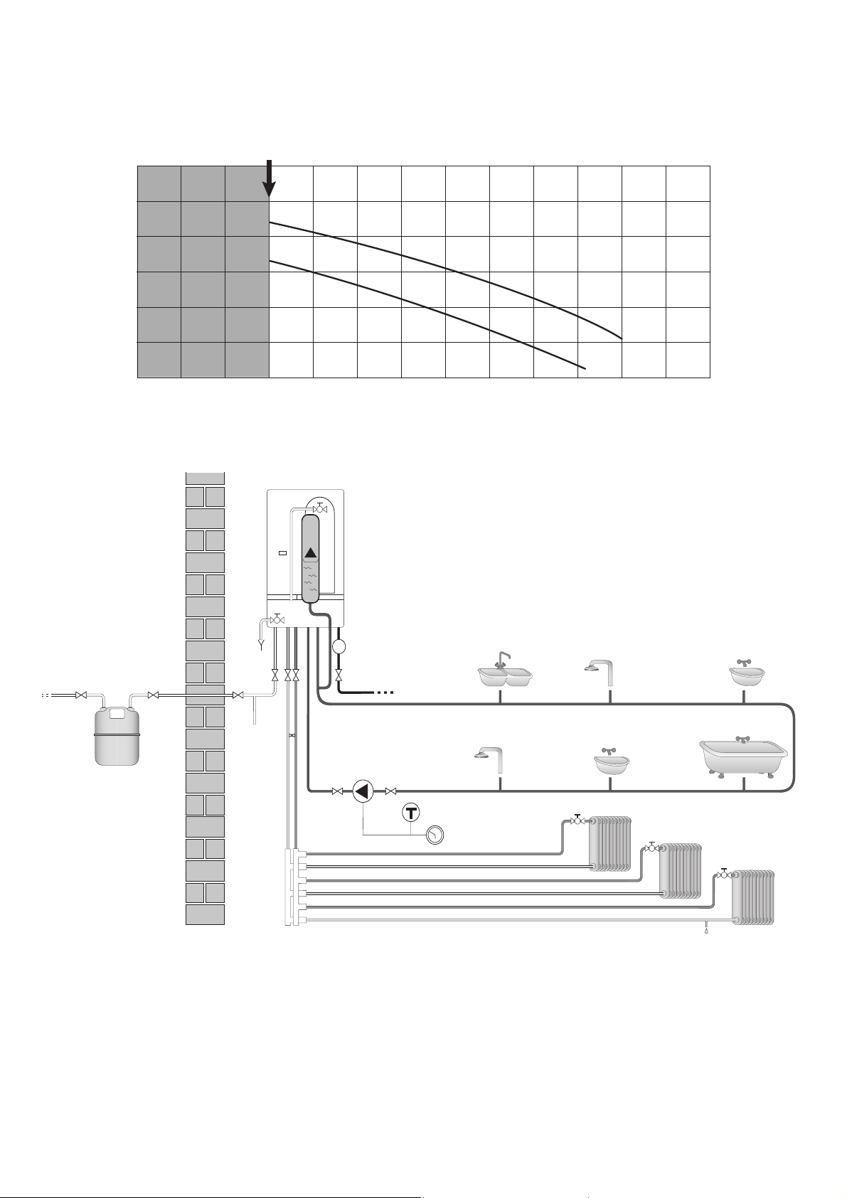
Operating Pressure
Fig. 10.5
A - Gas Inlet
B - C.H. Return
C - C.H. Flow
D - D.H.W. Secondary Return
E - D.H.W. Flow
F - C.W. Inlet
1 - Gas Meter Inlet Cock
2 - Gas Meter
3 - Gas Meter Outlet Cock
4 - Internal Gas Cock
5 - Appliance Gas Inlet Cock
6 - Cold Water Inlet Cock
7 - D.H.W. Expansion Vessel
8 - Cock
9 - Secondary Return Pump
10 - Thermostat
11 - Time Control Clock
12 - T&P Valve
13 - Tundish
Residual Head of the Boiler ΔT = 20oC
Fig. 10.6
m/H2O
mCE
Minimum flow (thermostatic valves closed)
6
5
4
3
2
1
GV
PV
0
100
200
300
400
500
600
700
800
900
1000
1100
1200
l/h
16
7
12
BC D E F
A
13
31
2
5
4
Other
Users
Pressure
V
Reducing Valve
6
Cold Water Inlet
9
8
8
10
11
Drain Tap
(at lowest point)
Page 22
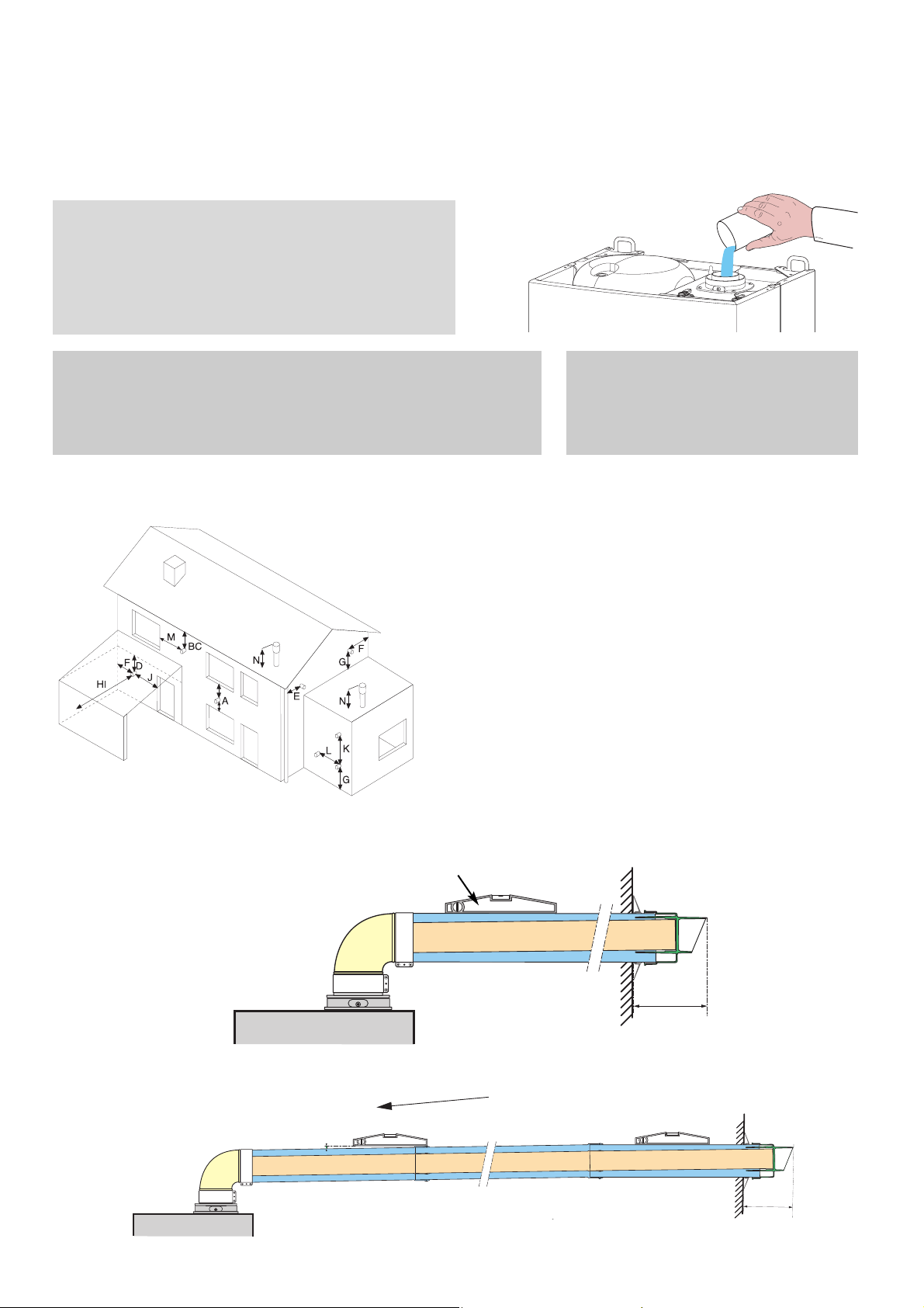
22
Fig. 11.1
T
ERMINALPOSITION
mm
A - Directly above or below an openable window
or other opening 300
B - Below gutters, solid pipes or drain pipes 75
C - Below eaves 200
D - Below balconies or car-port roof 200
E - From vertical drain pipes and soil pipes 150
F - From internal or external corners 300
G - Above ground or balcony level 300
H - From a surface facing a terminal 600
I - From a terminal facing a terminal 1200
J - From an opening in the car port
(e.g. door, window) into dwelling 1200
K - Vertically from a terminal in the same wall 1500
L - Horizontally from a terminal in the same wall 300
M - Horizontally from an opening window 300
N - Fixed by vertical flue terminal
11. Connecting the Flue
The boiler should only be installed with a flue system supplied by MTS (GB) Limited.
These kits are supplied separately to the appliance in order to respond to different installation solutions. For more information
with regard to the inlet/outlet accessories consult the accessory catalogue. The boiler is supplied ready for connection to a
concentric flue system.
N
OTE:SEE PAGE 28 FOR MAXIMUM AND MINIMUM FLUE RUNS (TABLES A, B AND C)
Warning
The exhaust gas ducts must not be in contact with or close to inflammable
material and must not pass through building structures or walls made of
inflammable material.
When replacing an old appliance, the flue system must be changed.
Important
Ensure that the flue is not blocked.
Ensure that the flue is supported and
assembled in accordance with these
instructions.
IMPORTANT!!
BEFORE CONNECTING THE FLUE, ENSURE THAT 1/4 LITRE OF
WATER HAS BEEN POURED INTO THE EXHAUST CONNECTION
TO FILL THE CONDENSATE TRAP
. SHOULD THE TRAP BE
EMPTY THERE IS A TEMPORARY RISK OF FLUE GASSES
ESCAPING INTO THE ROOM.
Installation without extension
Installation with extension
Level
slope 5 mm per metre
slope
* pente
* pente 5 mm par mètre
150 mm
150 mm
Page 23
23
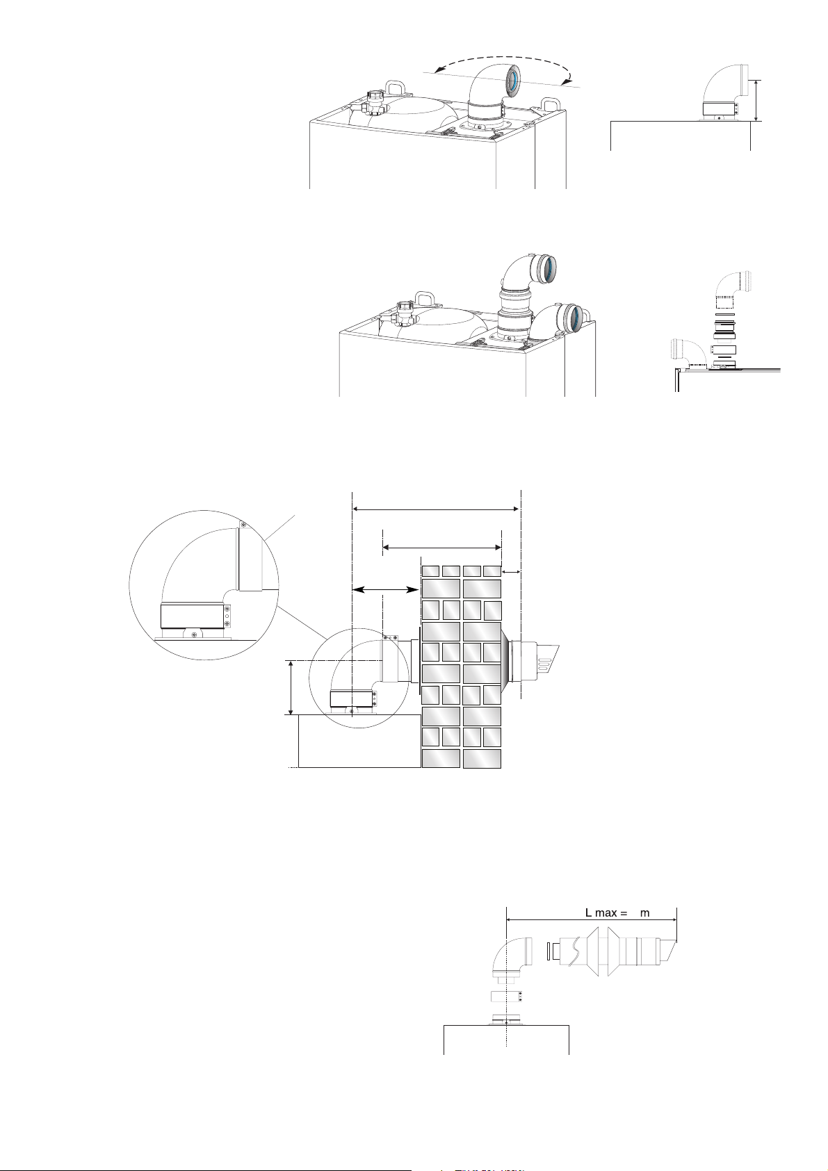
Fig. 11.2
In addition, it is also possible to use a split
system by fitting a special adapter to the flue
discharge collar and using one of the
apertures for the air vent intake located on
the top part of the combustion chamber.
NOTE:THE FLUE MUST TERMINAL MUST
BE AT LEAST
2 METRES FROM ANY
OPENING IN A BUILDING OPPOSITE AND
SHOULD NOT DISCHARGE ACROSS
BOUNDARIES
. IN ADDTION TO THIS, THE
FLUE MUST NOT TERMINATE IN A PLACE
LIKELY TO CAUSE NUISANCE
.
Fig.11.3
153
Ø 60/100 mm
4
Fig.11.4
4
136
Flue
Clamp
145 mm
Maximum Lenght = 3 m
Minimum Lenght = 370 mm
95 mm
100 mm
X
107 mm
5
Page 24
24
C
ONTENTS
:
1XS
ILICONE
O-R
ING
(60mm)
1XE
LBOW
(90O)
2
XWALLSEALS(INTERNAL&EXTERNAL
)
1XF
LUEPIPE INCLUDINGTERMINAL
(1
METRE
- 60/100)
1
XFLUECLAMP
1XS
CREWS
1x Seal
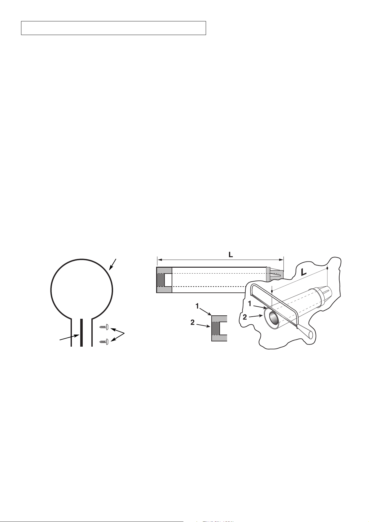
Once the boiler has been positioned on the wall, insert the elbow into the socket and rotate to the required position. NOTE: It is
possible to rotate the elbow 360oon its vertical axis.
Using the flue clamp, seals and screws supplied (Fig 11.5) secure the elbow to the boiler.
The 1 metre horizontal flue kit (3318073) supplied is suitable for an exact X dimension of 815mm.
Measure the distance from the face of the external wall to the face of the flue elbow (X - Fig 11.4), this figure must now be
subtracted from 815mm, you now have the total amount to be cut from the plain end of the flue.
Draw a circle around the outer flue and cut the flue to the required length taking care not to cut the inner flue, next cut the inner
flue ensuring that the length between the inner and outer flue is maintained. (Fig 11.5).
e.g.
X = 555mm
815-555 = 260mm (Length to be cut from the plain end of the flue).
Once cut to the required length, ensure that the flue is free from burrs and reassemble the flue. If fitting the flue from inside of
the building attach the grey outer wall seal to the flue terminal and push the flue through the hole, once the wall seal has
passed through the hole, pull the flue back until the seal is flush with the wall. Alternatively, the flue can be installed from
outside of the building, the grey outer seal being fitted last.
Fig. 11.5
Screws
Clamp
Seal
11.1 Fitting the coaxial flue (Ø 60/100 Horizontal)
Page 25
25
NOTE:SEE PAGE 28 FOR MAXIMUM AND MINIMUM FLUE RUNS.
C
ONTENTS
:
1
XSILICONE
O-R
ING
(60 mm)
1XC
ONICALADAPTOR
(60/100 mm)
1XV
ERTICALFLUEKIT
(80/125 mm)
3
XSCREWS
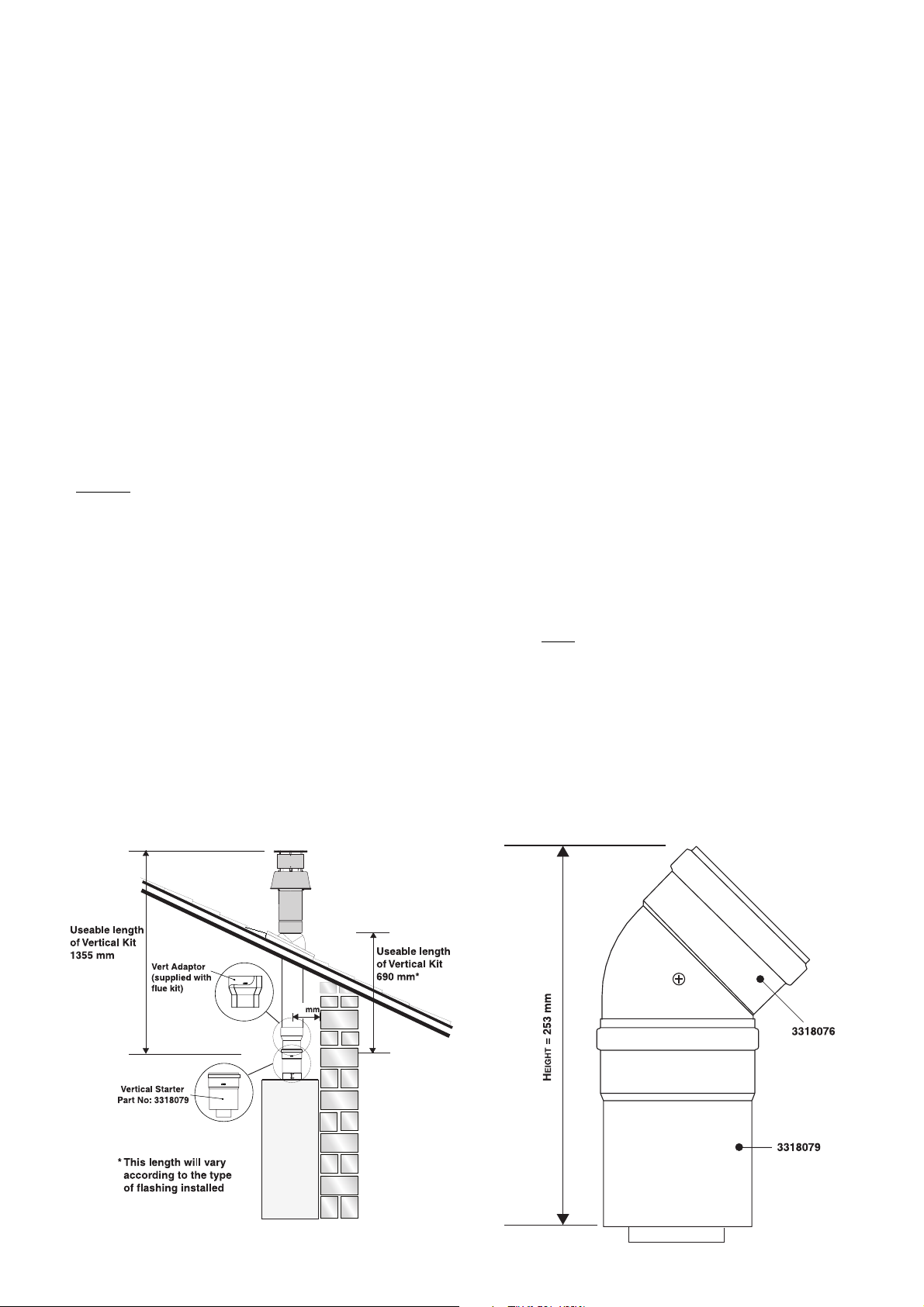
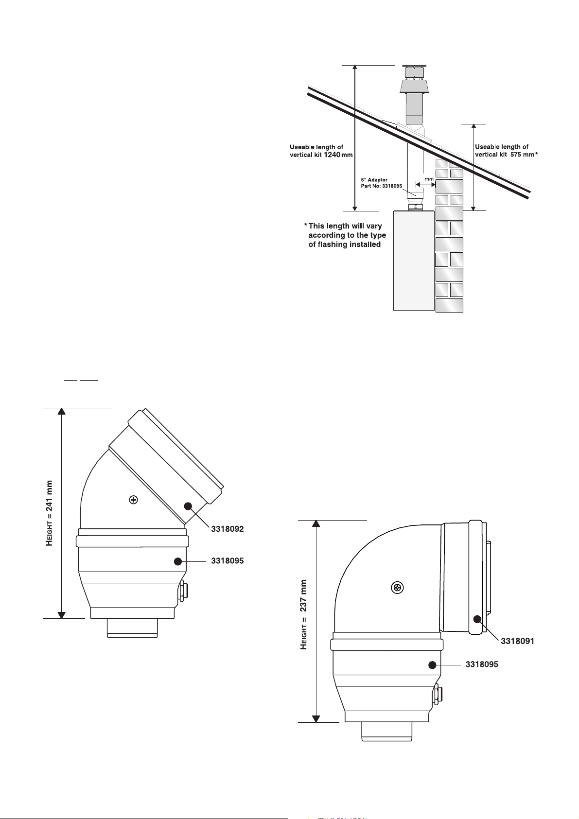
The vertical flue kit is supplied with a specially designed weather proof terminal fitted, it can be used either with a flat roof or a
pitched roof.
The Vertical flue kits useable lengths with the pitched roof flashings are indicated in Fig. 11.6.
Before proceeding to fit the flue, ensure that the maximum flue length has not been exceeded (See the tables on Page 20) and
that all elbows and bends have been taken into consideration, the maximum flue length is 4 metres, for each additional 90
o
elbow 1 metre must be subtracted from the total flue length, and for each 45o0.5 metres must be subtracted from the total flue
length (the height of the vertical adaptor and a 45obend can be seen in Fig. 11.7).
Mark the position of the flue hole in the ceiling and/or roof (see Fig. 11.6 for distance from wall to the centre of the flue).
Cut a 120 mm diameter hole through the ceiling and/or roof and fit the flashing plate to the roof.
DO
NOT
cut the vertical flue kit.
To connect the vertical flue kit directly to the boiler, place the vertical starter kit (Part No. 3318079) (see Figs. 11.6 & 11.7)
onto the exhaust manifold and secure with the clamp, fit the vertical adaptor onto the vertical starter kit (note: there is no need
to use a clamp to secure this as it is a push fit connection), the vertical flue kit must then be inserted through the roof flashing,
this will ensure that the correct clearance above the roof is provided as the terminal is a fixed height.
Should extensions be required, they are available in 1 metre (Part No. 3318077), 500 mm (Part No. 3318078) and 160 mm
lengths, they must be connected directly to the vertical starter kit before connecting the adaptor to allow the vertical flue kit to
be fitted. In the event that extension pieces need to be shortened, they
must
only be cut at the male end and it must be
ensured that the inner and outer flue remain flush.
When utilising the vertical flue system, action must be taken to ensure that the flue is supported adequately to prevent the
weight being transferred to the appliance flue connection by using 1 flue bracket per extension.
When the flue passes through a ceiling or wooden floor, there must be an air gap of 25 mm between any part of the flue
system and any combustible material. The use of a ceiling plate will facilitate this. Also when the flue passes from one room
to another a fire stop must be fitted to prevent the passage of smoke or fire, irrespective of the structural material through
which the flue passes.
11.2 Fitting the Coaxial Flue (Ø 60 / 100 Vertical)
Fig. 11.6
Fig. 11.7
153
Page 26
26
11.3 Fitting the 5” Flue (Ø 80 / 125 Horizontal/vertical)
Should the flue require extending, the flue connections are
push fit, however, one flue bracket should be used to secure
each metre of flue.
N
OTE:SEE PAGE 28 FOR MAXIMUM AND MINIMUM FLUE RUNS.
Once the boiler has been positioned on the wall, it is
necessary to insert the Ø80/125 adaptor (F
IG. 11.8) for both
horizontal and vertical flue runs into the boiler flue socket
(not supplied with flue kit - Part No 3318095).
Push the adaptor onto the boilers flue connection, grease
the seals then add extensions or elbows as required, secure
the adaptor, using the clamp and screws provided.
To fit extensions or elbows it is first necessary to ensure that
the lip seal is fitted correctly into the inner flue, once
verified, it is simply necessary to push them together, no
clamps are necessary to secure the flue components.
Before proceeding to fit the flue, ensure that the maximum
flue length has not been exceeded (See the tables on Page
20) and that all elbows and bends have been taken into
consideration, the maximum flue length is 10 metres, for
each additional 90
o
elbow 1 metre must be subtracted from
the total flue length, and for each 45o0.5 metres must be
subtracted from the total flue length (the height of the
vertical adaptor and a 45
o
bend can be seen in Fig. 11.9
and a 90obend in Fig. 11.10).
NOTE: DO NOT CUT THE VERTICAL FLUE KIT.
Fig. 11.8
Fig. 11.9
Fig. 11.10
153
Page 27
27
11.4 Fitting the twin pipe (Ø80/80)
NOTE:SEE PAGE 28 FOR MAXIMUM AND MINIMUM FLUE RUNS (TABLE C)
Where it is not possible to terminate the flue within the distance permitted for coaxial flues, the twin flue pipe can be used by
fitting a special adaptor to the flue connector and using the aperture for the air intake located on top of the combustion
chamber.
Always ensure that the flue is adequately supported, avoiding low points. (MTS supply suitable clamps as Part No. 705778).
To utilise the air intake it is necessary to:
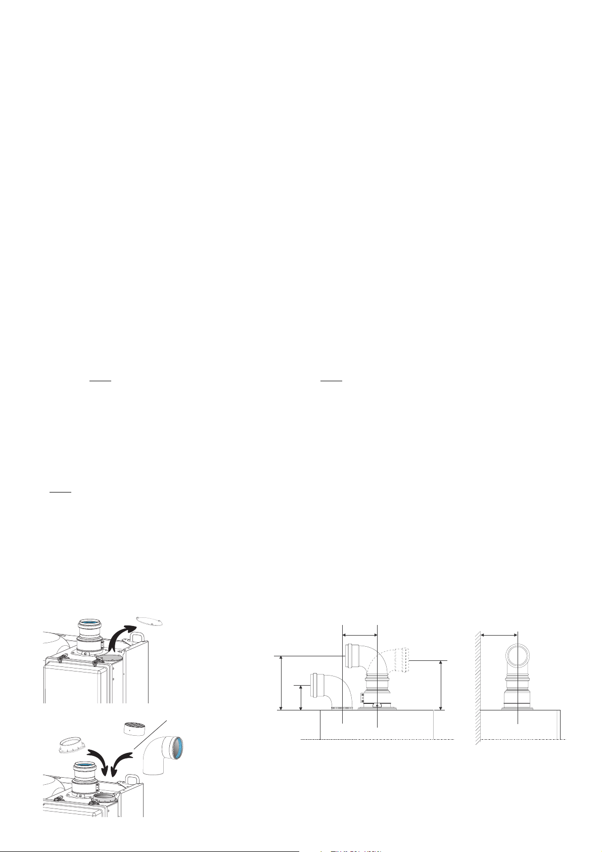
1) Take the air intake cover off
2) Assemble the flange on the header supplied with the boiler
3) Insert the restrictor if necessary, on the tube or the elbow
4) Insert the header on the tube or the elbow up until the lower stop
(you do not have to use the washer).
5) Insert the elbow/header in the boiler air intake hole and fasten it with screws
The twin flue pipes can be fitted with or without additional elbows and need no clamps, simply ensure that the red o-ring is
inserted in the female end of the flue pipe and push the extension piece fully into the previous section of flue pipe or elbow,
check that the o-ring is not dislodged when assembling the flue.
Twin pipe can also be converted back to Coaxial flue to enable vertical termination with a coaxial kit by using the pipe bridge
(Twin - Coaxial Adaptor - Part No. 705767). When running the twin flue pipe vertically.
It is not recommended that the pipe bridge for horizontal termination, however in the unlikely event that this proves to be a
necessity it is extremely important that the entire flue has a fall of 5mm in every metre back to the boiler, and where the 60mm
inner flue of the concentric terminal connects to the pipe bridge, this point must be adequately sealed with silicone sealant to
avoid condense leakage at this point.
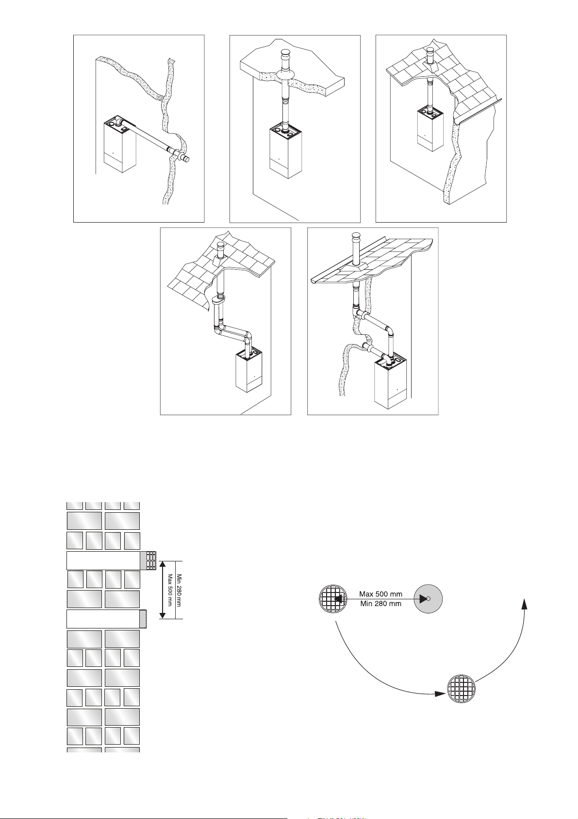
When siting the twin flue pipe, the air intake and exhaust terminals must terminate on the same wall, the centres of the
terminals must
be a minimum of 280 mm apart and the air intake must not be sited above the exhaust terminal (refer to Fig.
29). The air intake pipe can be run horizontally, however, the terminal and the final 1 metre of flue must be installed with a fall
away from the boiler to avoid rain ingress.
It is also strongly recommended that the air intake pipe run be constructed of insulated pipe to prevent condense forming on
the outside of the tube.
The maximum permissible flue length for twin flue is dependent on the type of run used.
For flue runs with the intake and exhaust pipes under the same atmospheric conditions (T
YPE 4) the maximum length is 60
metres (24kW and 30kW), for runs with the terminals under different atmospheric conditions (T
YPE 5) the exhaust terminal
must
extend 0.5 metres above the ridge of the roof (this is not obligatory if the exhaust and air intake pipes are located on the
same side of the building). For T
YPE 5 also, the maximum permissible combined length is 60 metres (24kW and 30kW).
The maximum length is reached by combining the total lengths of both the air intake and exhaust pipes. Therefore a maximum
length of 60 metres for example, will allow a flue run of 30 metres for the air intake and 30 metres for the exhaust pipes, also
for each 90
o
elbow 2.2 metres must be subtracted from the total length and for each 45oelbow 1.4 metres must be subtracted
from the total flue length.
Some of the acceptable flue configurations are detailed on page 29.
For further information relating to flue runs not illustrated, please contact the Technical Department on 0870 241 8180.
Fig. 11.12
Fig. 11.13
123,5 162
B23
C53
230 MIN *
132
200
Page 28
28
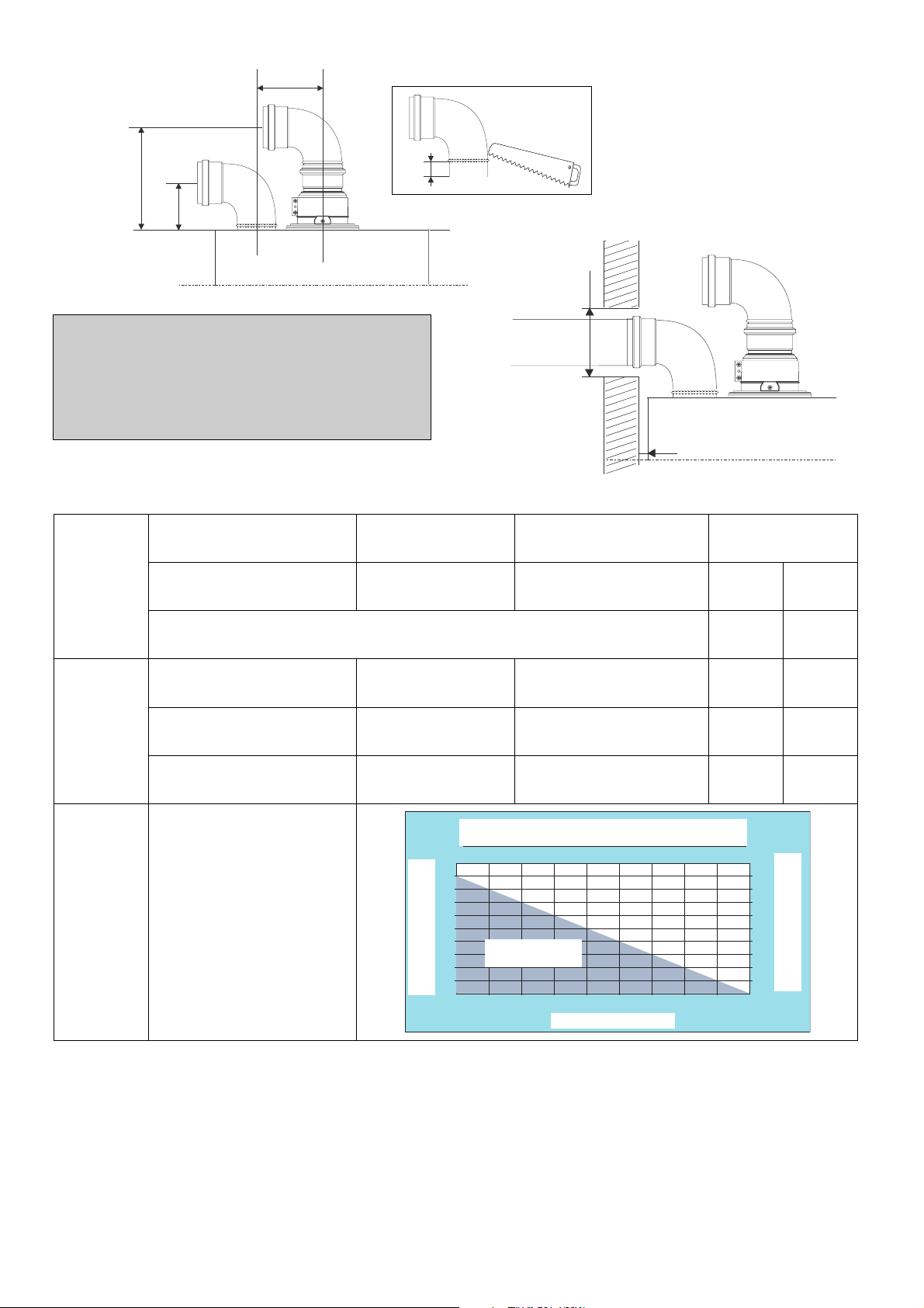
For coaxial systems, the maximum development value, mentioned in the table above also takes into account an elbow.
For twin flue systems the maximum development value, mentioned in the table includes the exhaust gas/air intake terminal.
Type 5 outlets should respect the following instructions:
1- Use the same ø 80 mm flue pipes for the gas intakes and exhaust gas ducts.
2- If you need to insert elbows in the gas intake and exhaust gas ducts, you should consider for each one the equivalent length
to be included in the calculation of developed length.
3- The exhaust gas duct should jut above the roof by at least 0.5 m.
4- The intake and exhaust gas ducts in Type 5 must be installed on the same wall, or where the exhaust is vertical and the air
intake horizontal, the terminals must be on the same side of the building.
TABLE
A
Concentric outlet
60/100
Min length Max. length
Length
equivalency for
35 kW 0.3 m 4 m
45
o
elbow
0.5 m
90
o
elbow
1 m
TABLE
B
Concentric outlet
80/125
Min length Max. length
35 kW 0.3 m 10 m
45
o
elbow
0.5 m
90
o
elbow
1 m
TABLE
C
Twin flue outlet
35 kW
123,5
Fig. 11.14
In the event that twin flue pipes are used, and the boiler
has a side clearance of less than 60mm from the wall, it
is necessary to cut a larger diameter hole for the flue
pipe, this should be ø100 mm, this will then allow for
easier assembly of the air intake elbow and the tube
outside the wall (see Fig. 11.14).
Fig. 11.15
Operating zone in separate 35 kW ducts
Operating zone
Flue gas length in metres /
Horizontal
Flue gas length in metres /
vertical
Air length in metres
200
107
25
ø 100
60 mm
ZONE DE FONCTIONNEMENT EN CONDUITS SEPARES 35 kW
100
90
80
70
60
50
40
30
HORIZONTAL
20
Longueur fumées mètre
10
0
0 102030405060708090
ZONE DE
FONCTIONNEMENT
Longueur AIR mètre
200
180
160
140
120
100
VERTICAL
80
60
Longueur fumées mètre
40
20
0
Page 29
29
NOTE: DRAWINGS ARE INDICATIVE OF FLUEING OPTIONS ONLY.
TYPE 1
TYPE 5
TYPE 4
TYPE 3
TYPE 2
FIG. 11.16
FIG. 11.17
AIR INTAKE MUST NOT BE
FITTED ABOVE THE EXHAUST
AIR INTAKE
EXHAUST
AIR INTAKE
Page 30
30
12. ELECTRICAL CONNECTIONS
THERMOSTAT AMBIANCE
ROOM THERMOSTAT
B
C
Room thermostat
Connector
B
Side view of the
connection to the pre
cabled electrical box
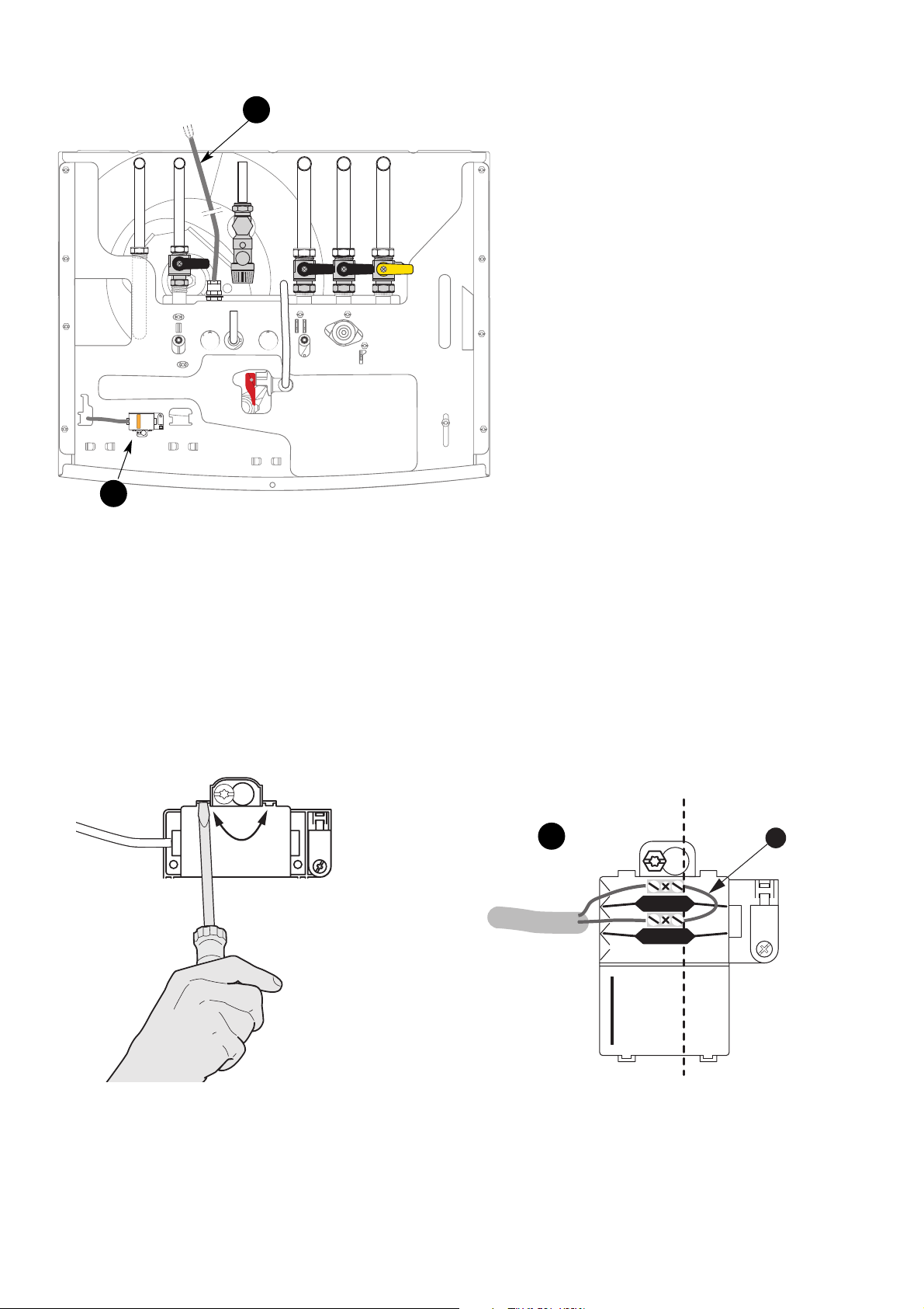
The 220-240 V and earth connection are made by
using the lead provided C (Fig. 12.1)
I
MPORTANT!!
C
ONNECTION SHOULD BE MADE VIA A 3 AMP FUSED DOU-
BLE POLE ISOLATING SWITCH WITH CONTACT SEPERATION
OF AT LEAST
3MM ON BOTH POLES. ALTERNATIVELY, A
FUSED
3 AMP, 3 PIN PLUG AND UNSWITCHED SOCKET MAY
BE USED
, PROVIDED IT IS NOT USED IN A ROOM CONTAIN-
ING A BATH OR SHOWER. IT SHOULD ONLY SUPPLY THE
APPLIANCE
.
External Controls
Open the cover B with a screwdriver (Fig. 12.2)
The room thermostat is connected onto this connector B (Fig. 12.1)
- remove the bridge S (Fig. 12.3)
- connect the thermostat in place of the bridge S (Fig.
12.3)
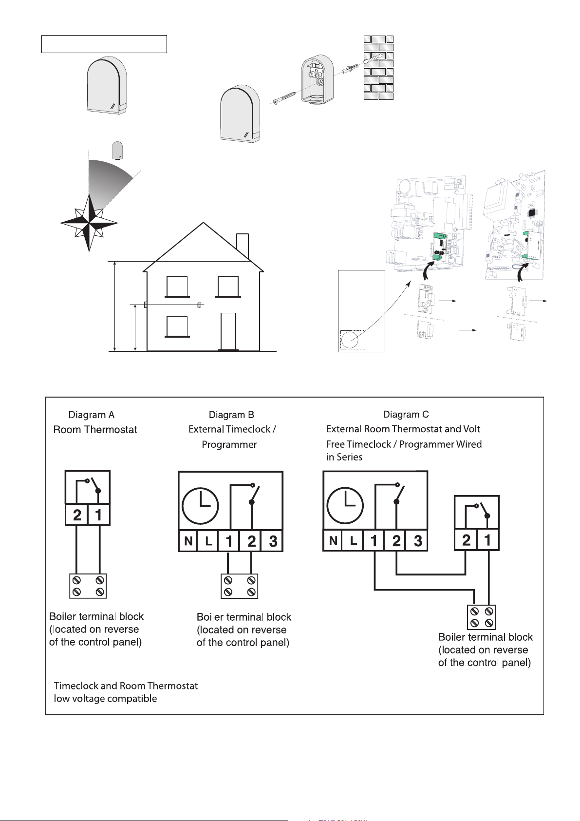
- If a remote time clock is to be fitted, using a volt-free
switching time clock, connect the wires from the time
clock following the points above. (see also Fig. 12.4)
Note: Before connecting an external time clock, disconnect the internal time clock as described in Section 18.3.4 (page 49)
FIG. 12.1
F
IG. 12.2
FIG. 12.3
Raccordement côté
boîtier électrique
pré-cablé
S
Page 31
31
Outside sensor
FIG. 12.4
N E
N
WE
S
H
1/2 H
05/2006
05/2006 05/2006
Page 32
32
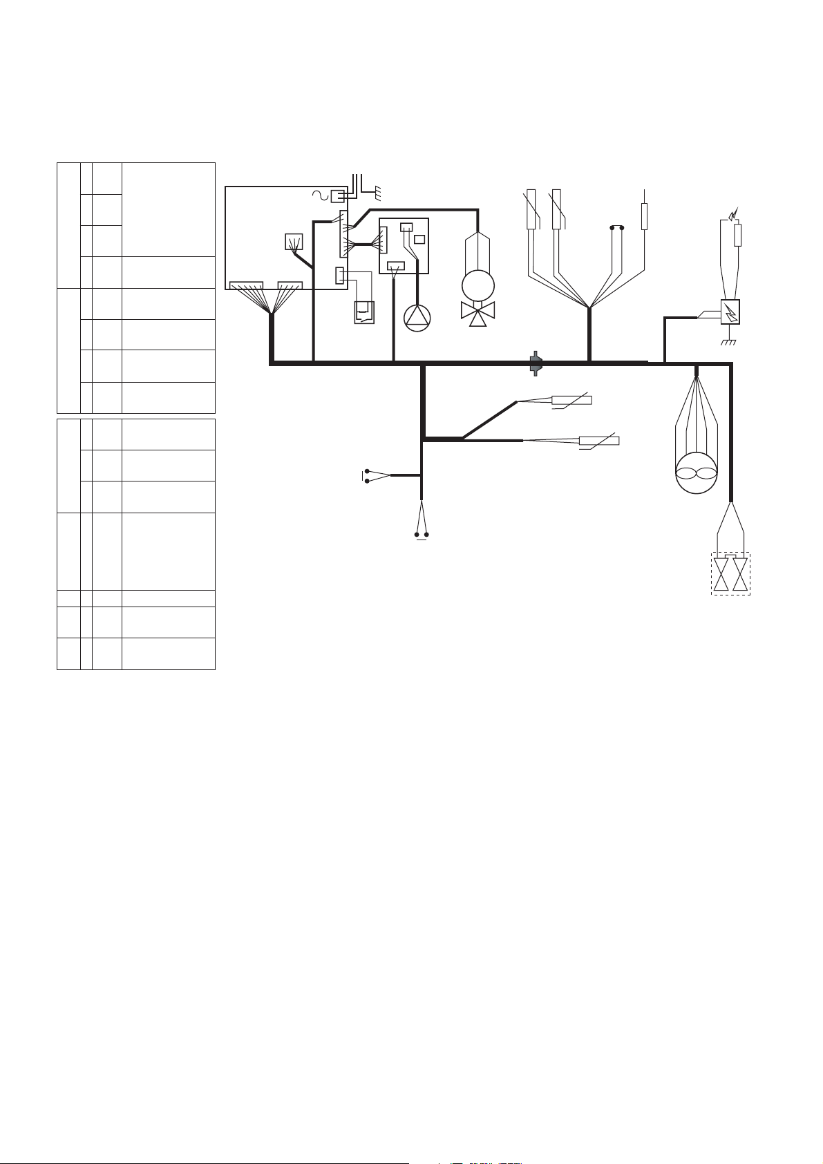
13. ELECTRICAL / SYSTEM DIAGRAMS
White
1
Blue
CN2
CNF
CN3 /
CN31
CN5CN8
CN12CN1
11
12
10
11
1
2
3
4
5
6
1
2
3
5
8
1
2
2
4
5
6
7
1
2
4
8
5
9
4
Yel lo w
Brown
Black
Red
Blue
Red
Grey
Grey
Black
Black
White
White
Purple
Purple
Grey
Grey
Black
Black
Red
Red
Blue
Yel lo w
Brown
Black
Red
White
Red
Blue
Yel lo w
/ Green
Interface
Card
Spark generator
Heating flow
thermistor
Heating return
thermistor
Domestic hot water
flowswitch
Domestic hot water
thermistor
Tank thermistor
Pressure switch
Overheating
safety device
Fan
Ionisation
Gas valve
Mass / Ground
Main supply
230V 50Hz
CN1
CN8 CN12
CN5
Room
thermostat
CN5
CNF
CN12 - 3
CN12 - 4
Pump
CN8 - 4
CN8 - 8
CN5 - 10
CN5 - 9
CN5 - 8
M
Three way
valve
CN8 - 1
CN8 - 5
CN8 - 9
CN8 - 10
CN8 - 2
CN12 - 1
CN12 - 2
CN8 - 11
CN12 - 5
CN12 - 6
CN2
CN1 - 1
CN1 - 4
CN5 - 11
CN5 - 12
CN1 - 3
CN1 - 5
CN1 - 2
CNF - 1
CNF - 2
Page 33
33
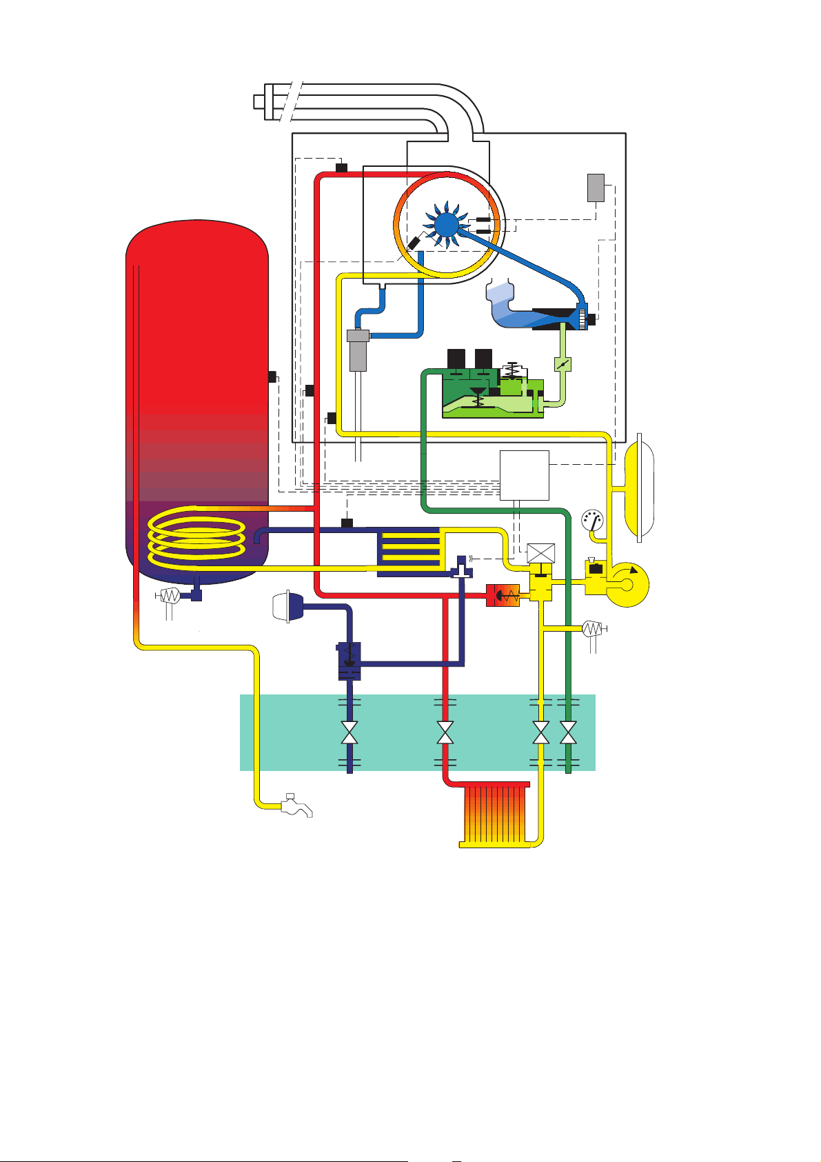
LEGEND :
1 – Main heat exchanger
2 - Burner
3 – Ignition electrodes
4 – Flame detection electrodes
5 – Modulating gas valve
6 – Spark generator
7 - Siphon
8 – Domestic hot water tank
9 – Water tank valve
10 – Heating flow thermistor
11 – Tank thermistor
12 – Hot water control thermistor
13 - Pump
14 – Secondary plate heat exchanger
15 – DHW activator
16 – Heating return thermistor
17 – Heating expansion vessel
18 – Three way valve
19 – Heating safety valve
20 – Pressure jauge
21 – Electrical box
22 – Overheat safety device
23 - Fan
24 – Fumes box
25 – Flue pipe
26 - By-pass
27 – Non return valve
28 – Gas tap
29 – Heating return tap
30 – Heating flow tap
31 – Water service tap
32 – DHW expansion kit
14. WATER CIRCUIT DIAGRAMS
25
22
24
6
1
3
2
4
8
23
11
7
10
5
16
17
21
12
14
20
18
15
13
9
32
26
19
27
2830 2931
Page 34
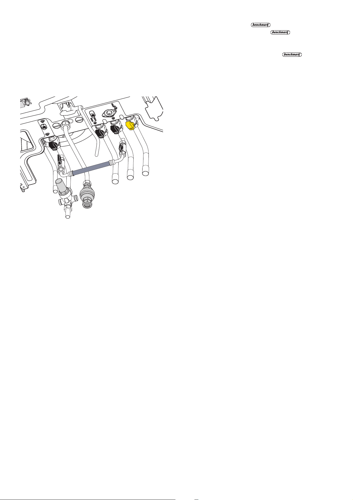
34
15.1 Initial Preparation
MTS (GB) Limited support the initiative. Within the
information pack you will find a copy of the Log Book. It is
important that this is completed in the presence of your customer,
they are shown how to use it, and it is signed by them. Please
instruct your customer that they must have their Log Book
with them whenever they contact a service engineer or us.
Preliminary electrical system checks to ensure electrical safety
must be carried out by a competent person i.e. polarity, earth
continuity, resistance to earth and short circuit.
F
ILLING THEHEATINGSYSTEM
:
Lower the control panel and remove the case panels (see
S
ECTION 15.3 for further information).
Open the central heating flow and return cocks supplied with the
connection kit.
Unscrew the cap on the automatic air release valve one full turn
and leave open permanently.
Close all air release valves on the central heating system.
Gradually open valve(s) at the filling point (filling-loop) connection
to the central heating system until water is heard to flow, do not
open fully.
Open each air release tap starting with the lowest point and close
them only when clear water, free of air, is visible.
Purge the air from the pump by unscrewing the pump plug
anticlockwise, also manually rotate the pump shaft in the
direction indicated by the pump label to ensure the pump is
free.
Refit the pump plug.
Continue filling the system until at least 1.5 bar registers on the
pressure gauge.
Inspect the system for water soundness and remedy any leaks
discovered.
F
ILLING OF THE
D.H.W. S
YSTEM
:
Close all hot water draw-off taps.
Open the cold water inlet cock supplied with the connection kit.
Open slowly each draw-off tap and close them only when clear
water, free of bubbles, is visible.
GASS
UPPLY
:
Inspect the entire installation including the gas meter and test for
soundness. The gas installation should be in accordance with the
relevant standards. In GB this is BS6891 and in IE this is the
current edition of I.S.813.
The connection to the appliance is a 15 mm copper tail located at
the rear of the gas service cock (Fig. 10.3).
If the gas supply for the boiler serves other appliances ensure
that an adequate supply is available both to the boiler and the
other appliances when they are in use at the same time.
Pipe work must be of an adequate size. Pipes less than the 22
mm should not be used.
Open the gas cock (supplied with the connection kit) to the
appliance and check the gas connections on the appliance for
leaks.
15. COMMISSIONING
FIG. 15.1
Page 35

35
When the installation and filling are completed, flush the system while
cold, refill, turn on the Central Heating system (S
ECTION 3) and run it
until the temperature has reached the boiler operating temperature.
The system must then be immediately flushed through.
The flushing procedure must be in line with BS 7593:1992 code of
practice for treatment of water in domestic hot water central heating
systems.
During this operation, we highly recommend the use of a central
heating flushing detergent (Fernox Superfloc or equivalent), whose
function is to dissolve any foreign matter that may be in the system.
Substances different from these could create serious problems to
the pump or other components.
The use of an inhibitor in the system such as Fernox MB-1 or
equivalent is strongly recommended to prevent corrosion (
sludge
)
damaging the boiler and system, following the flushing procedure..
Failure to carry out this procedure may invalidate the appliance
warranty.
For IE it is necessary to complete a “Declaration of Conformity” to
indicate compliance to I.S.813. An example of this is given in the
current edition of I.S.813. In addition it is necessary to complete the
“Benchmark” Log Book.
15.2 Completion
Page 36
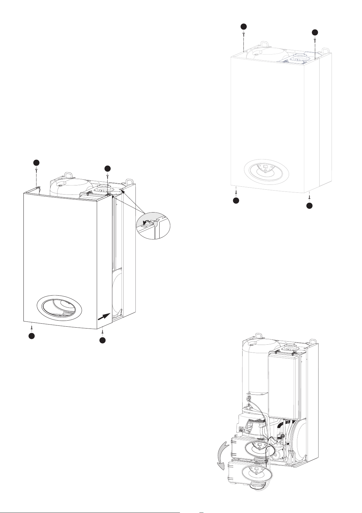
36
15.3 Removal and fitting of the case Servicing
Removal of the case
- undo the 4 case retaining screws (Fig. 15.2)
- disengage the clips
- remove the case
Fitting the case
Remove the protective film from the front and
rear of the case
- position the case (Fig. 15.3)
- engage both clips in the case (see detail)
- fasten the 4 retaining screws A on the front
Servicing
To maintain the unit, it is possible to move the electrical
box without having to disconnect it. The electrical box
is clipped onto the heating outlet pipe or onto the
bottom of the chassis. (Fig. 15.4)
detail
FIG. 15.2
FIG. 15.3
FIG. 15.4
A
A
A
A
A
A
A
A
Page 37
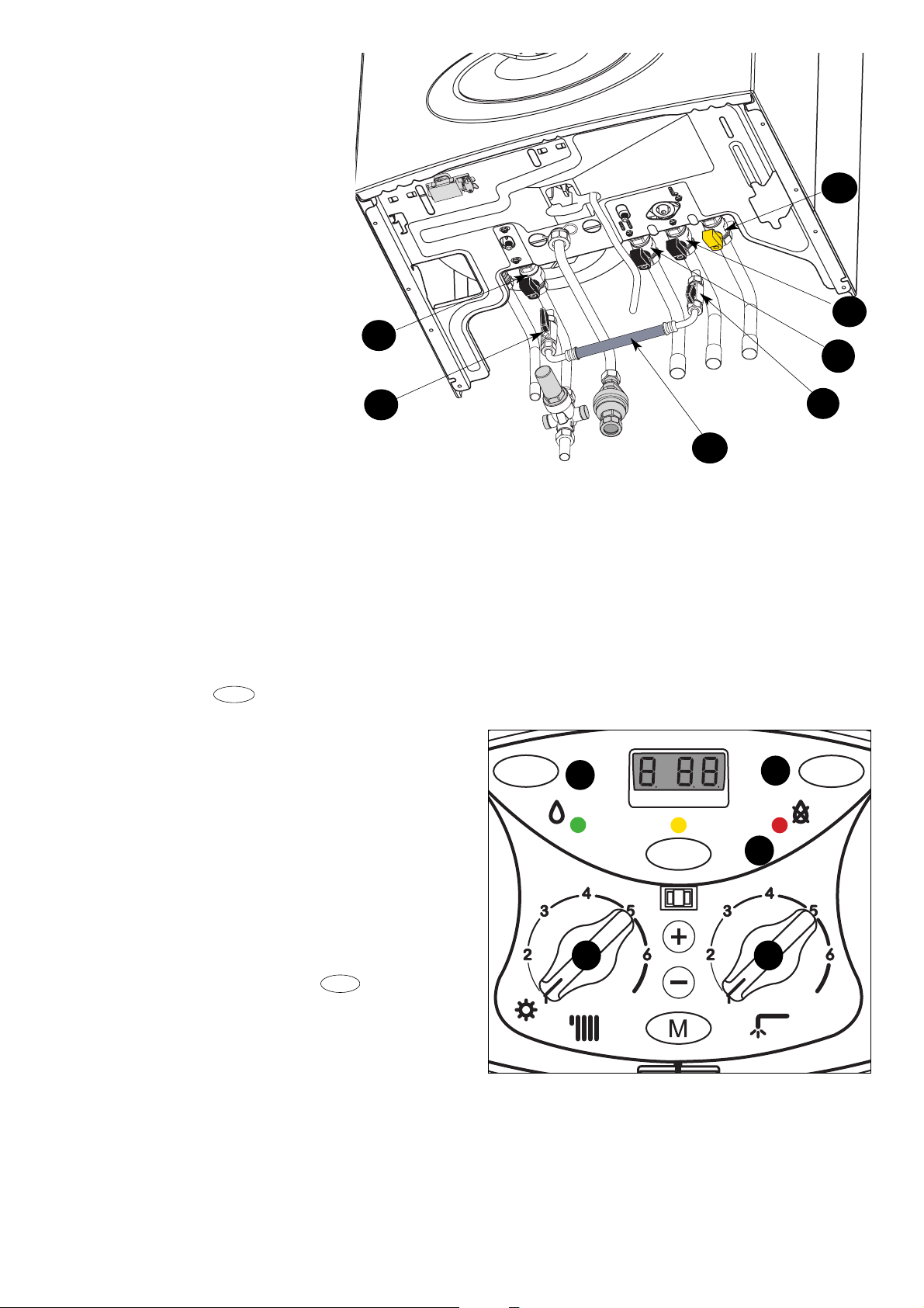
37
32 33
26
27
30
Fig. 15.6
41
42
43
44
45
39
40
Fig. 15.5
(fig. 15.5)
Domestic hot water circuit
- open cold water tap 40
- drain the hot water tank and appliance by
drawing off from the various hot water taps.
Heating circuit
- check that the heating outlet tap 41 and
heating return tap 42 are fully open
- open the filling taps 43 and 44
- close these taps when the needle of the
pressure gauge 37 (under the door of the
electrical unit cover) reaches the pressure
set in § 3
- drain the appliance and re-establish the
pressure
Gas circuit
- open the gas tap 39
- flush the gas circuit
- check the sealing over the whole gas circuit
(fig. 15.6)
- press the on/off button 26 on the control panel and
turn selector 32 to the “winter” operating mode. The boiler
pump will start up and three attempts will be made to ignite
the burner (display
S01
, then
S02
. After the third attempt,
the electronic control unit will shut the appliance down as
the gas supply has been cut off; the warning light 30 comes
on and “
A01
” appears on the display.
- leave the pump running until all the air has been
exhausted from the appliance.
- bleed the air from the radiators
- open the Domestic hot water circuit to eliminate all the air
from it
- check the appliance pressure, and if it has fallen, add
water to bring it back to 1 bar.
- check the exhaust gas evacuation duct.
- check that the ventilator inlets for the room are fully open
(type B appliances).
6. Reset the boiler by pressing the button 27.
The burner comes on. If the first attempt fails, the gas pipe
must be purged;
repeat the operation until the burner ignites.
RESET
ON/OFF
15.4 Pressurisation
15.5 Commissioning
WARNING : It is very important to fully bleed the main heat exchanger of air when filling the boiler.
You must continue to bleed the heat exchanger from pump through the automatic air vent, through several
central heating and hot water cycles to ensure the air is fully bled from the system.
Refer to the installation manual for detailed guidance.
Failure to adequately bleed the boiler may damage the appliance and invalidate the warranty.
ON/OFF
COMFORT
RESET
Page 38
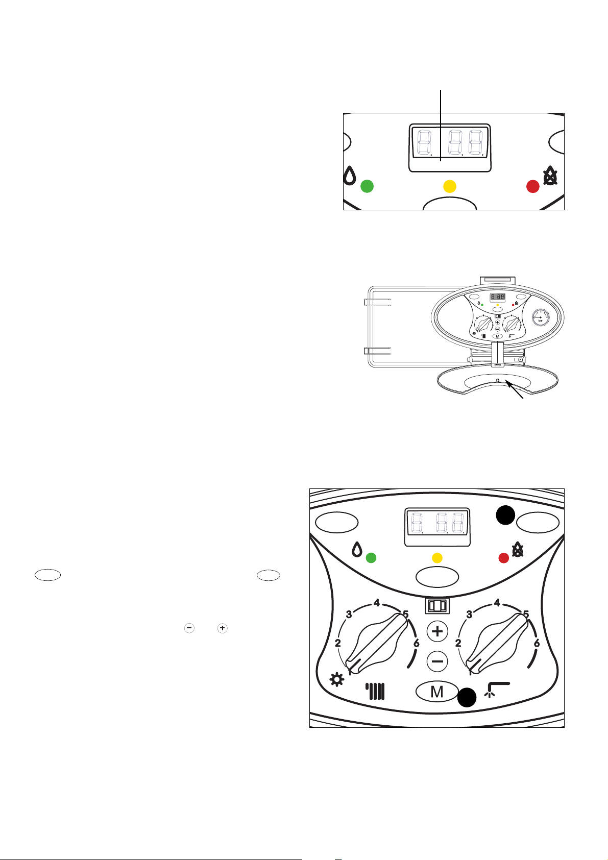
38
Fig. 15.8
P
R
27
36
Fig. 15.7
Fig. 15.9
The appliance is preset in the factory. The preset factory settings are
given in the menu table.
All the settings can be changed by the installer or a qualified professional.
The settings and information on the boiler are accessible by tilting door P
of the electrical unit (fig. 15.8).
Display: display of operations in progress (fig. 15.7)
During operation of the boiler, in other words when it is performing its
normal functions, the left side of the display shows a series of characters
referring to the operations, as indicated below:
0
No heat command
C
Heating
c
Pump in post-circulation mode for heating
d
Domestic hot water
h
Pump in post-circulation mode for Domestic hot water
b
Tank reheating
On the right, the display shows (2 characters):
- in heating mode: heating appliance output temperature
- in Domestic hot water distribution mode: drawing-off temperature.
- in tank reheating mode: tank temperature.
Left-hand display
< Right-hand display
Operating adjustment (fig. 15.9)
The boiler has been designed to simplify the setting of the
operating parameters.
Adjustment menu
To access the adjustment menu, first press the Reset button
27 and, holding it down, press the Menu button 36
for 5 seconds.
By pressing the Reset button again, the screen will display the
parameters shown in the menu table.
To change the parameters, use the and programming
buttons.
M
RESET
15.6 Settings
ON/OFF
ON/OFF
RESET
COMFORT
RESET
COMFORT
Page 39
39
Parameter Function Adjustment range Factory settings
1
Ignition power as %
00
to
99 %
(step: 1%)
55
Consult the manufacturer
before changing this
parameter
2
Maximum heating power (%)
00
to
99 %
(step: 1%)
66
3
Anti-cycle timer (minutes)
00
to
07 minutes
(step: 1 minute)
02
4
Minimum heating outlet temperature
25° to 42 °C if parameter r = 00
42° to 81 °C if parameter r = 01
42
5
Maximum heating outlet temperature
26° to 75 °C if parameter r = 00
43° to 82 °C if parameter r = 01
82
6
Not used
00
to
99 45
tS
E@sy remote surveillance
0
or
1
0
Do not alter if the E@sy
system is not connected
F
Type of boiler
00
to
03
03 do not alter (boiler
with tank)
E
External actuator (depending on system)
00
to
03 00 do not alter
P
Post-circulation with pump in heating mode
from 01to
15 minutes or C0 02
C
Activation/deactivation of Domestic hot
water function
00
or
01 00
PU
Pump speed control
U0
or
U1 U1
r
Heating setpoint range
00
or
01 01
P
Temperature control by external sensor
90
or
91 90
P6
Gradient shift
- 20to +
20 °C 0
P5
Gradient adjustment
0_1
to
5_0 0_9
T
Test function Not used
A
Not used
b0
Second zone set-point
25
to
82 75
b1
Not used
b2
Post Domestic hot water timer in minutes
00
to
30 00
b3
Not used
b4
Programmer action
0
to
2
0
on heating and tank reheating
1
on tank reheating
2
on heating
0
b5
Not used
b7
Not used
b8
Not used
Important!! The parameters P5, P6and P9are only activated if the external sensor is connected.
To return to the standard displays, press the Menu button.
MENU TABLE
Page 40
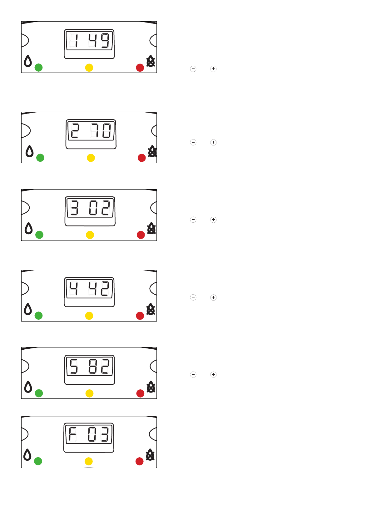
40
Ignition power output setting
1
This parameter limits the power of the boiler in the ignition phase.
Possibility of adjusting ignition between maximum power (display of
"99", i.e. 100%) and minimum power (display of "00", i.e. 0%).
The percentage expresses the usable power value between the
minimum and maximum power value.
Use the and buttons in menu 1 to select the required value.
The factory-set value is given in the menu table.
Anti-cycle timer
3
This parameter sets the delay between 2 successive burner ignitions in
heating mode.
It is possible to select an ignition delay of between 1 and 7 minutes.
Use the and buttons in menu 3 to select the required value.
The factory-set value is given in the menu table.
Maximum heating outlet temperature
5
This parameter sets the maximum heating outlet temperature in
relation to r.
Use the and buttons in menu 5 to select the required value.
The factory-set value is given in the menu table.
Minimum heating outlet temperature
4
This parameter sets the minimum heating outlet temperature in relation
to r.
Use the and buttons in menu 4 to select the required value.
The factory-set value is given in the menu table.
Maximum heating power regulation
2
This parameter limits the power of the boiler in the heating phase.
The percentage expresses the power value between the minimum and
maximum power value.
Use the and buttons in menu 2 to select the required value.
The factory-set value is given in the menu table.
Selection of boiler type
F
Pre-set in factory:
This parameter must not be altered.
Page 41
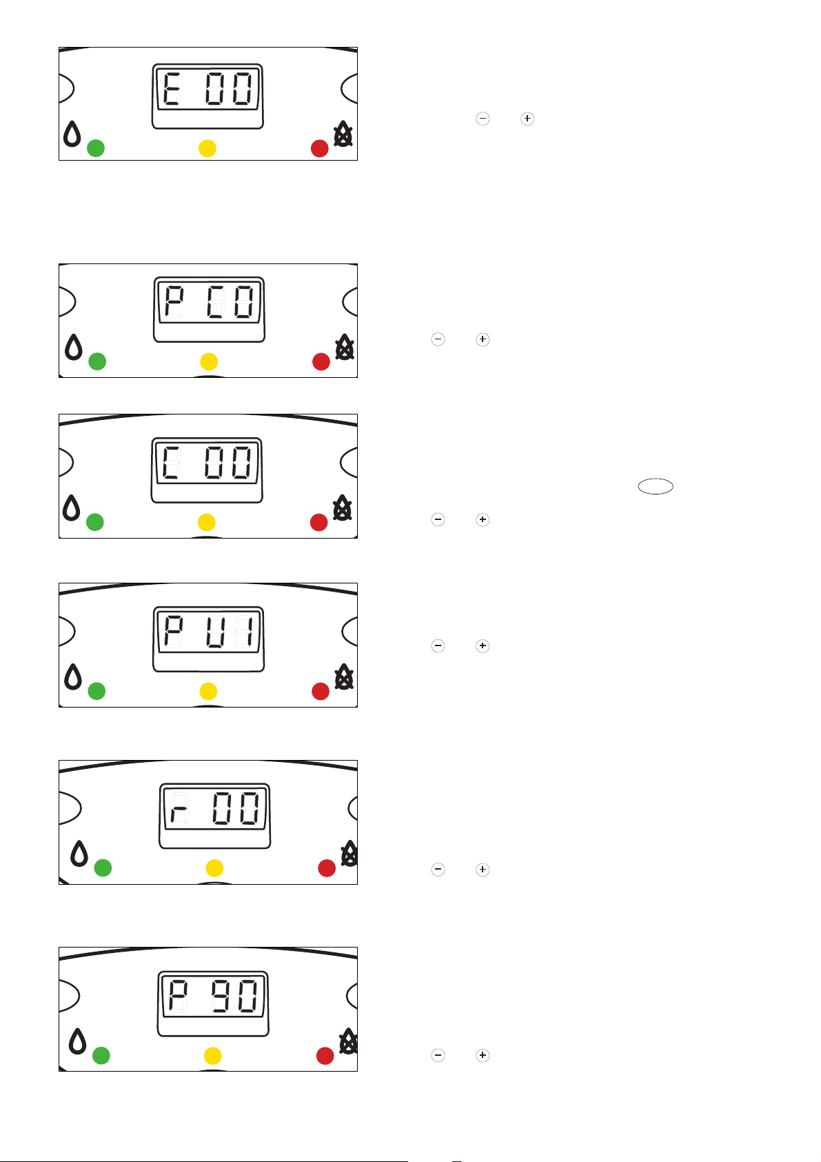
41
Selection of Secondary Output operation
E
Only activated if peripheral interface card connected (option)
For connection of peripherals to the motherboard, refer to the user
instructions for the Clima Manager or the external sensor. Parameter E
is altered by the and programming buttons.
00
Zone valve - factory setting
01
NOT USED
02
NOT USED
03
NOT USED
Circulation pump post-circulation
P
The appliance allows variation of the post-circulation period of the
circulation pump after extinction of the burner. Adjustable from 1 to 15
minutes or continuous (
CO
).
Use the and buttons in menu P to select the required value.
The factory-set value is given in the menu table.
Comfort Function : activation/deactivation of the Domestic hot
water and tank reheating functions
C
00
Domestic hot water and tank reheating functions deactivated
01
Domestic hot water and tank reheating functions activated
When the function is activated, the yellow indicator light 31 comes on.
To deactivate the Comfort function, press the button.
The yellow indicator light 31 goes out.
Use the and buttons in menu C to select the required value.
The factory-set value is given in the menu table.
COMFORT
Circulation pump speed
P
U0
- Fixed speed operation
U1
- Variable speed operation
Use the and buttons in menu P to select the required value.
The factory-set value is given in the menu table.
Heating temperature range setting
r
00
- possibility of adjusting the temperature from 25°C to x in menu 4
possibility of adjusting the temperature from x+1 to 75°C in menu 5
where x ≤ 44 °C
01
- possibility of adjusting the temperature from 42°C to y in menu 4
- possibility of adjusting the temperature from y+1 to 82°C in menu 5
where y ≤ 81 °C
Use the and buttons in menu r to select the required value.
The factory-set value is given in the menu table.
Temperature control by external sensor
P
(Only activated if the external sensor is installed)
“
90
” Temperature adjustment by external sensor deactivated (external
sensor not installed).
“
91
” Temperature adjustment by external sensor activated (external
sensor installed).
Use the and buttons in menu P to select the required value.
The factory-set value is given in the menu table.
Page 42
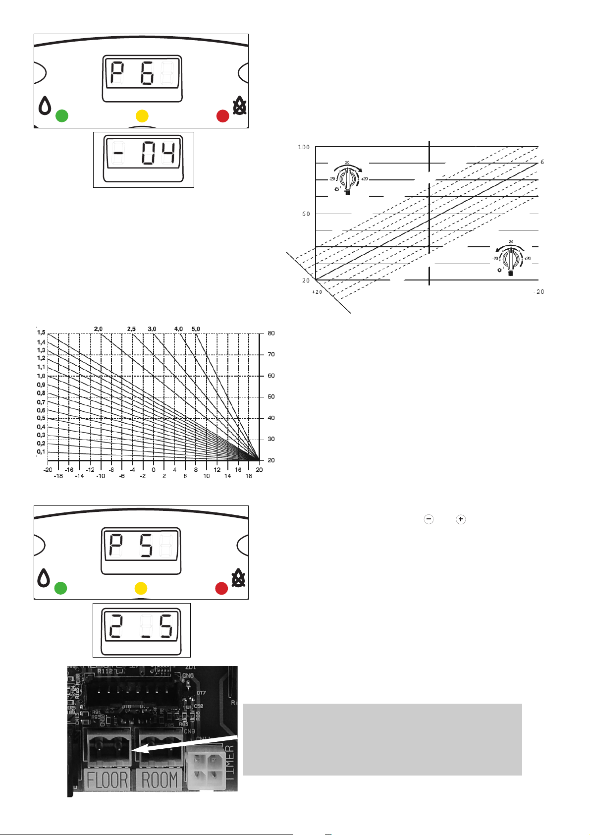
42
Adaptation of the selected thermal curve
P 6
(Only activated if the external sensor is installed)
To adapt the thermal curve to the appliance requirements, by selecting
the
P 6
parameter it is possible to perform a parallel shift of the curve
in order to alter the calculated outlet temperature and therefore the
environmental temperature.
When the screen displays
P 6
, by using the heating setting button it is
possible to perform a parallel shift of the curve as shown below. The shift
value between -20 and +20 is shown on the display.
Selection of thermal curves
P 5
(Only activated if the external sensor is installed)
If the external sensor is used, the microprocessor calculates
the most suitable heating outlet temperature taking the
external temperature and the type of installation into account.
The microprocessor can do this because it is possible to
establish a link between the external temperature and the
outlet temperature of the water. This link is expressed by a
“thermal curve”.
The type of curve must be chosen according to the type of
appliance and the heat losses present in the building.
Important
When selecting a curve for low-temperature appliances, it is vitally
important to connect an overheat safety device to the base output
which will be connected to the Flora room thermostat connector on the
boiler PCB.
The screen first displays the
P 5
parameter, then the curve selected.
To change the curve selection, use the and programming
buttons.
Note:
If the choice of curves is made using the Clima Manager remote
control, the available values are limited. Please refer to the remote
control user instructions.
parallel curve shift - increase
parallel curve shift - decrease
external T (°C)
outlet T (°C)
external T (°C)
outlet T (°C)
Page 43
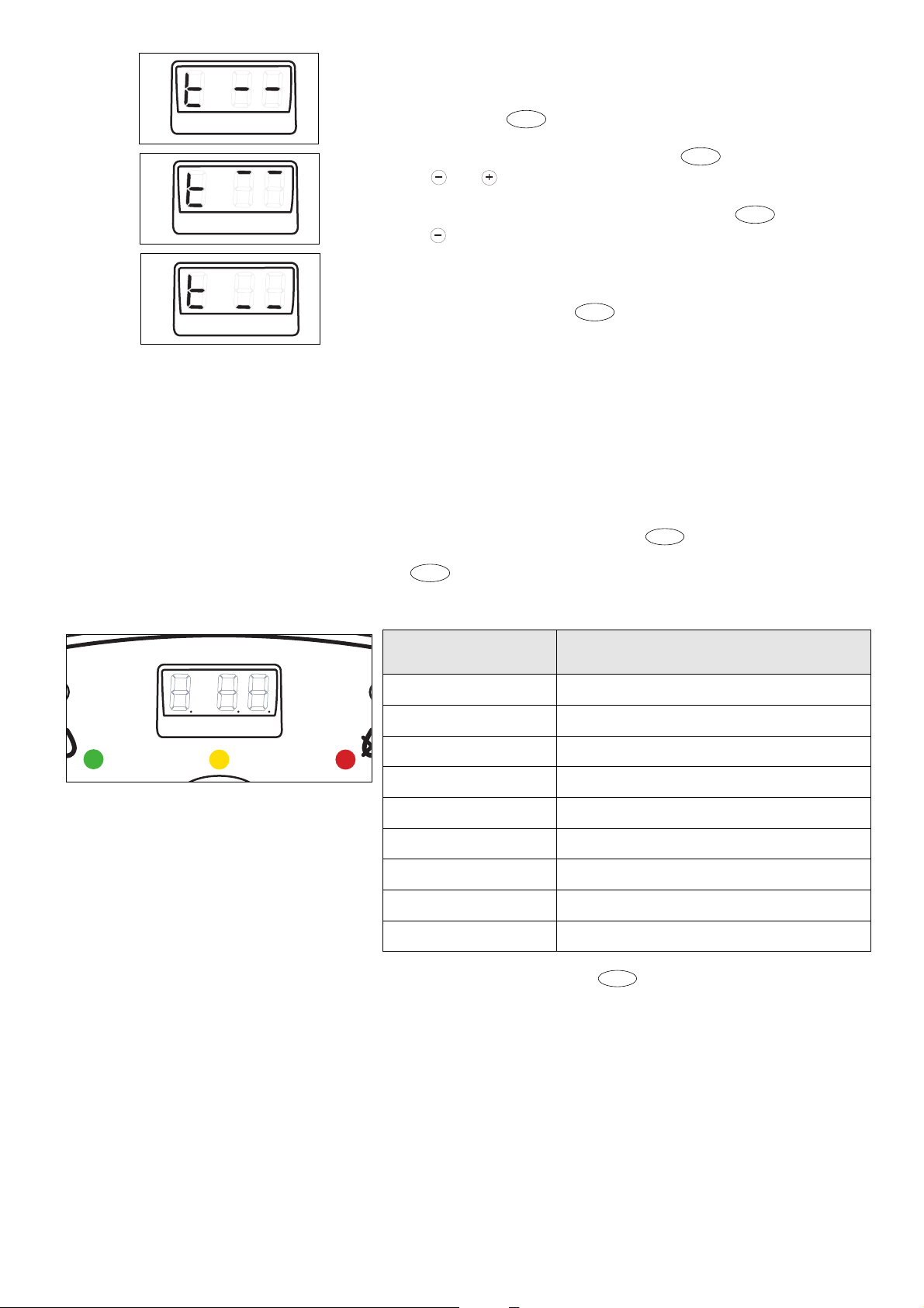
43
Test function
T
The boiler can be turned to maximum or minimum power without activating the test
function by using the settings menu:
a - press the reset button for 5 seconds to automatically turn the boiler to its
maximum power; the screen will display two dashes in the middle and to the right
of the screen. To deactivate this function press the button again.
b - press the and buttons simultaneously to turn the boiler to its maximum
Domestic hot water power; the screen will display two dashes at the top and to
the right of the screen. To deactivate this function press the button again.
c - press the button to turn the boiler to minimum power; the screen will display
two dashes at the bottom and to the right of the screen. To deactivate this
function press the button again.
To deactivate this function press the button again.
RESET
RESET
RESET
RESET
RESET
The boiler is designed to operate according to function and setting variables
using the control panel display. Press the Menu button for 10 seconds
to access the function allowing you to read the main system variables. Press
the button continuously to read the following information in sequence:
RESET
M
Selection display
To return to the standard displays, press the Menu button.
The boiler will automatically return to the standard displays after 2 minutes.
Note 1:
U/1(U/2.....) indicates that the display alternately displays U and 1 (U and 2, etc.)
Note 2:
the value 100% is displayed as "00".
* only with external sensor connected
M
Value shown on
the left-hand display
Value shown on right-hand display
U/1
Heating outlet temperature (°C)
U/2
Return temperature (°C)
U/3
Domestic hot water drawing off temperature (°C)
U/4
External temperature (°C)
U/5
Tank temperature (°C)
U/6
Fan rotation speed (Value X 100 rpm)
U/7
NOT USED
E
Last safety shutdown
A
Last operating stoppage
Page 44
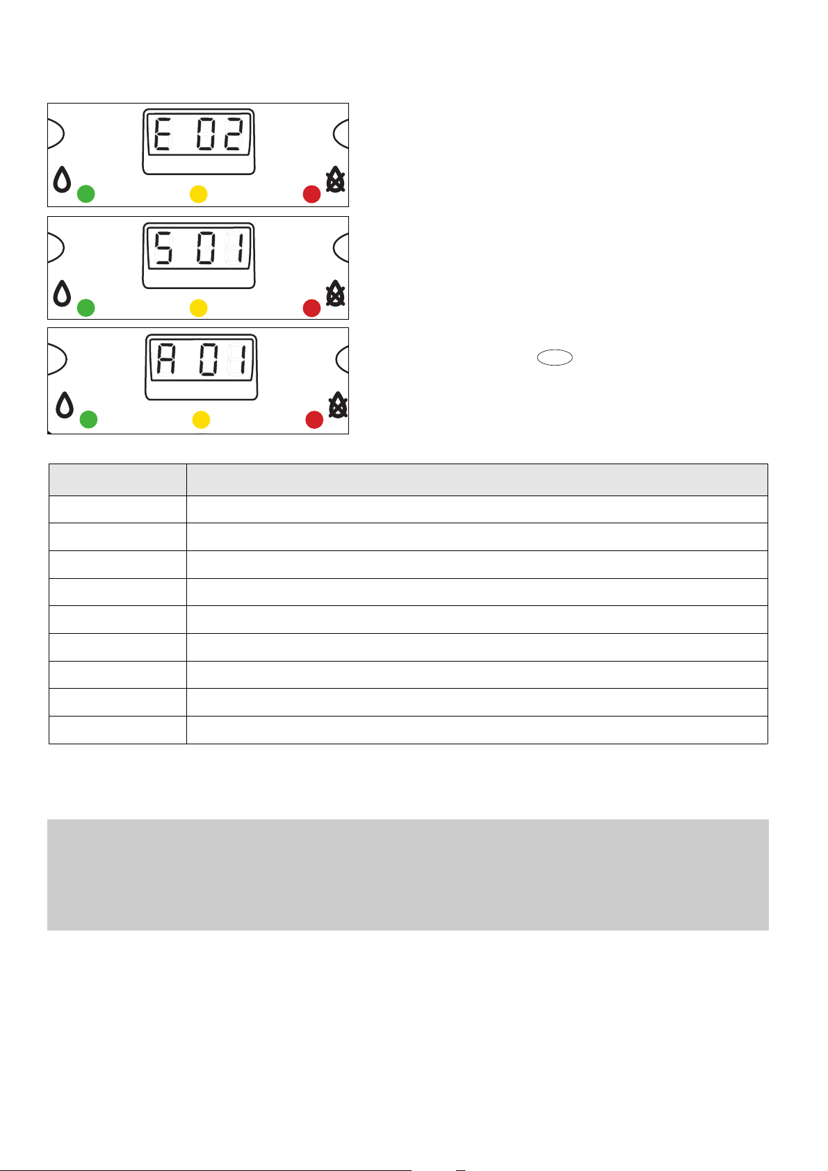
44
The boiler is protected against the risk of breakdown by internal checks
carried out by the microprocessor which, if necessary, will activate a
safety shutdown.
If the appliance stops working, the screen will display a code
corresponding to the type of stoppage and its cause.
There are two types of stoppage:
-
SAFETY SHUTDOWN
: this type of fault (indicated on the display by
the letters
"E" or"S"
) is of the "VOLATILE" type, in other words it is
automatically cleared when its cause ceases.
As soon as the cause of the stoppage disappears, the appliance will
restart and resume normal operation. While the boiler is in safety
shutdown mode, it is possible to attempt to restore operation by
switching it off and then on again.
-
OPERATING STOPPAGE
: this type of fault is called "NON
VOLATILE" (indicated on the display by the letter
"A"
) and in this
case, the appliance does not automatically restart.
To reset the boiler, press the key 27. If, after several attempts
to reset, the appliance stops again, call a qualified technician.
The following is a list of the stoppage types and the corresponding
codes displayed on the screen.
RESET
IMPORTANT
If this type of failure occurs too often, call an approved after sales technical service. For safety reasons, the boiler will only allow
5 reignition attempts in 15 minutes (pressing of the RESET button). After the fifth attempt, the boiler goes into safety shutdown
mode
E 99
.
No problem in the case of sporadic or isolated stoppages.
Display CAUSE
A01
Three ignition attempts
A03
The output temperature exceeds 105°C during operation
A07
Too many flame separations over a period during operation
A17
Input water circulation fault
A18
No water circulation
A33
Fan problem
A97
Electronic control problem
A98
Electronic control problem
A99
Electronic control problem
N.B.: In the case of an ignition fault, check that the gas tap is open.
15.7 Operating faults
Page 45
45
Antilocking of pump and three-way valve
To prevent locking of the components, the appliance performs a self-test every 24 hours: the pump starts up for 3 seconds and the
diverting valve is operated.
Frost protection
The boiler is fitted with an anti-freeze device, which checks the heating outlet temperature of the boiler: if this temperature falls
below 8°C, the pump starts up (circulation within the heating appliance) and runs for 2 minutes.
After two minutes' circulation, the microprocessor carries out the following check:
a - if the outlet temperature is > 8°C, the pump stops;
b - if the outlet temperature is > 3°C and < 8°C the pump continues for a further 2 minutes;
c - if the outlet temperature is < 3°C, the burner is ignited (in heating mode at minimum power) until a temperature of 33°C is
reached. Once this temperature is reached, the burner switches off and the circulation pump continues to operate for a further two
minutes.
It is possible to cause the pump to operate continuously using parameter P in the settings menu (see menu table).
The antifreeze protection is only activated if the boiler is in perfect working order,
in other words:
- the appliance water pressure is sufficient;
- the boiler is receiving an electrical supply;
- gas is being supplied.
Display CAUSE
S 01
Flame not detected on first attempt
S 02
Flame not detected on second attempt
S 04
Open circuit on Domestic hot water sensor
S 05
Short circuit on Domestic hot water sensor
S 06
Flame separation
S 25
Tank sensor open
S 26
Tank sensor short circuit
S 27
Tank overheating
S 30
External sensor open circuit
S 31
External sensor short circuit
S 80
Open circuit or short circuit on room sensor of the Clima Manager remote control
Display CAUSE
E 02
Insufficient water pressure
E 06
Open circuit on heating outlet sensor
E 07
Short circuit on heating outlet sensor
E 08
Open circuit on heating return sensor
E 09
Short circuit on heating return sensor
E 10
Contact open in the floor overheat safety device circuit (Flora room thermostat)
E 20
False flame detection with gas valve closed
E 94
Electronic control problem
E 95
Read error in heating outlet and return sensors
E 99
5 resets in less than 15 minutes. Resetting by a boiler ON/OFF operation
Page 46

46
It is recommended that the following checks be made on the
boiler at least once a year:
1 - Check the seals for the water connections; replacement of any
faulty seals.
2 - Check the gas seals; replacement of any faulty gas seals.
3 - Visual check of the entire unit.
4 - Visual check of the combustion process and cleaning of the
burners if needed.
5 - If called for by check no. 3, dismantling and cleaning of the
combustion chamber.
6 - If called for by check no. 4, dismantling and cleaning of the
injectors.
7 - Visual check of the primary heat exchanger:
- check for overheating in the blade assembly;
- clean the exhaust fan if needed.
8 - Adjustment of the flow rate of the gas: flow rate for lighting, partial load §
and full load.
9 - Check of the heating safety systems:
- safety device for maximum temperature;
- safety device for maximum pressure.
10 - Check of the gas safety systems:
- safety device for lack of gas or flame ionisation (detection
electrode);
- safety device for gas cock.
11 - Check of the electrical connection (make sure it complies with the
instructions in the manual).
12 - Check of domestic hot water production efficiency (delivery rate and
temperature)
13 - Check pressure in the Domestic Expansion Vessel and top up as
necessary.
14 - Check manually by turning the test knob of the Temperature &
Pressure Relief Valve.
15 - Check manually by turning the test knob the Expansion Relief Valve.
16 - Check discharge pipes from both the central heating and domestic
hot water for obstructions.
17 - Check of the general performance of the unit.
18 - General check of the discharge/ventilation of the combustion by
products.
N
OTE:THESE CHECKS ARE NOT EXHAUSTIVE
17. MAINTENANCE
16. GAS CONVERSION
In the event of converting to a gas type other than that for which the boiler has been designed, the parts delivered with
the conversion kit must be fitted.
Page 47
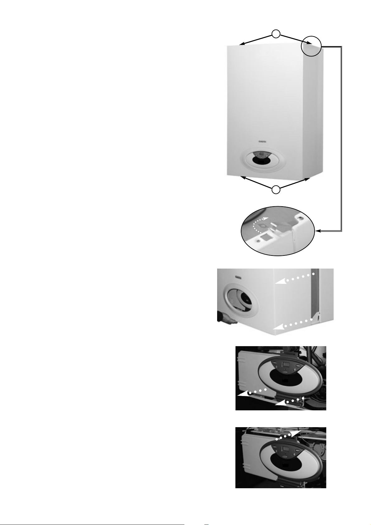
47
18. Servicing Instructions
The life of individual components vary and they will need
servicing or replacing as and when faults develop.
The fault finding sequence chart in Section 19 will help to locate
which component is the cause of any malfunction, and
instructions for removal, inspection and replacement of the
individual parts are given in the following pages.
18.1 Replacement of Parts
18.2 To Gain General Access
To ensure efficient safe operation, it is recommended that the
boiler is serviced annually by a competent person.
Before starting any servicing work, ensure both the gas and
electrical supplies to the boiler are isolated and the boiler is
cool.
Before and after servicing, a combustion analysis should be
made via the flue sampling point (please refer to Section 15.8).
After servicing, preliminary electrical system checks must be
carried out to ensure electrical safety (i.e. polarity, earth
continuity, resistance to earth and short circuit).
A
All testing and maintenance operations on the boiler require the
control panel to be lowered. This will also require the removal of
the casing.
Fig. 18.3
Fig. 18.1
Fig.18.2
Fig. 18.4
Fig. 18.5
A
18.2.1 Removing the front panel
1.
Remove the 4 retaining screws “A” (see Fig. 18.1);
2.
Disengage the 2 clips (see Fig. 18.2);
3.
Remove the front panel from the rest of the casing (see Fig.
18.3).
4.
Reassemble in reverse order.
18.2.2 Removing the control panel
1.
Remove the front panel as above;
2.
Pull the control panel toward you to disengage it from the
bottom of the chassis (see Fig. 18.4);
3.
Clip the top of the control panel onto the bottom of the
chassis. (see Fig. 18.5);
4.
Reassemble in reverse order.
Page 48
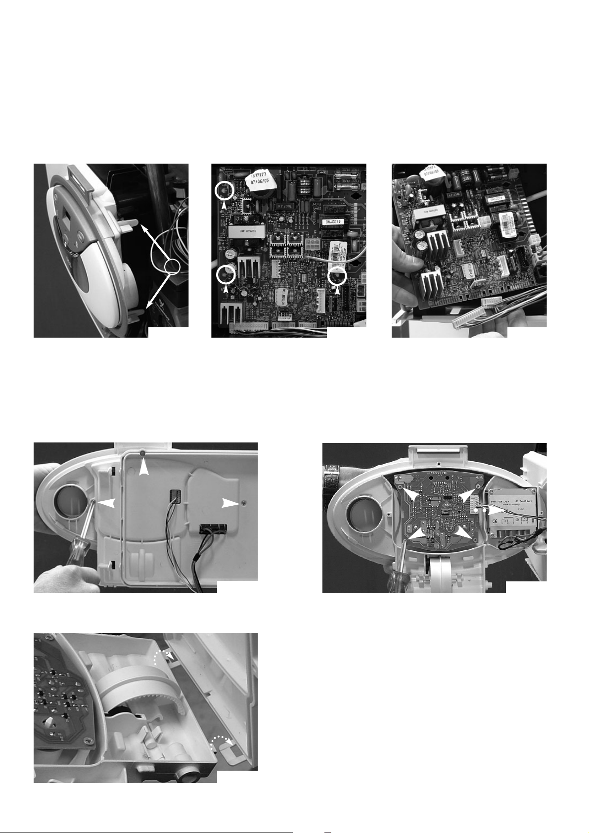
48
18.3 Access to the Control System
18.3.1 Removing the main P.C.B.
6.
Disconnect the remaining
connectors (see Fig. 18.8 );
7.
Reassemble in reverse order.
1.
Isolate electricity and carry out step
18.2.1
;
2.
Open the control box by pushing on
the 2 right clips “B1” (see Fig. 18.6 );
3.
Push on the pressure gauge to
disengage it;
4.
Disconnect as possible the
connectors on the P.C.B. ;
5.
Compress the three peripheral
plastic parts “B2” to unlock the fitting
P.C.B. , and pull it toward you
simultaneously (see Fig. 18.7);
1.
Isolate electricity and carry out step
18.2.1
;
2.
Open the control box as above (see Fig. 18.6);
3.
Remove the three screws on the control box (see Fig.
18.9);
Fig. 18.10
Fig. 18.9
Fig. 18.11
Fig. 18.6
Fig. 18.7 Fig. 18.8
B1
B2
B2
B2
18.3.2 Removing the display P.C.B.
4.
Remove the four screws on the P.C.B., then pull the
card toward you and remove the connector (see Fig.
18.10);
5.
Reassemble in reverse order and carry out the good
positioning on the control box (see Fig. 18.11).
Page 49
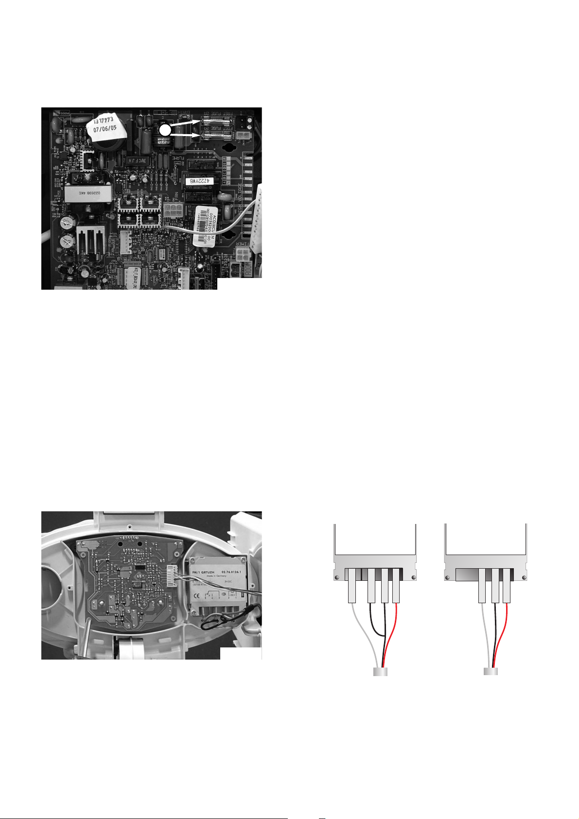
49
18.3.4 Removing the time clock
Fig. 18.13
To fit the integral time clock it is necessary to proceed
as follows; (this should only be carried out by a
competent engineer)
1.
Isolate the electrical supply to the appliance;
2.
Remove the front panel as described in step
18.2.1
;
3.
Open the electrical box as in step
18.3.1
and remove
the plastic cover as in step
18.3.2
(see Fig. 18.13) ;
4.
Pull out the wires;
N
OTE: THE WIRES MAY BE TUCKED BEHIND THE
ELECTRICAL COVER.
5.
Connect the time clock wires as follows and
reassemble in reverse order.
1.
Isolate electricity and carry out step
18.2.1
;
2.
Open the control box as in step
18.3.1
(see Fig. 18.6);
3.
Remove the fuses “C” (see Fig.18.12);
4.
Reassemble in reverse order.
18.3.3 Removing the fuses
C
Fig. 18.12
MECHANICAL MODEL (Fig. 18.14)
Red Wire - Contact 1
Black Wire - Contact 2
Black Wire - Contact 3
Grey Wire - Contact 5
N
OTE: THE TWO BLACK WIRES ON CONTACTS 2 & 3 CAN BE
REVERSED
DIGITAL MODEL (Fig. 18.15)
Red Wire - Contact 1
Black Wire - Contact 2
Grey Wire - Contact 3
N
OTE:SECOND BLACK WIRE IS NOT CONNECTED.
Fig. 18.14
Fig. 18.15
5
3
B
1
2
R
G
3
1
2
R
B
4
G
Page 50
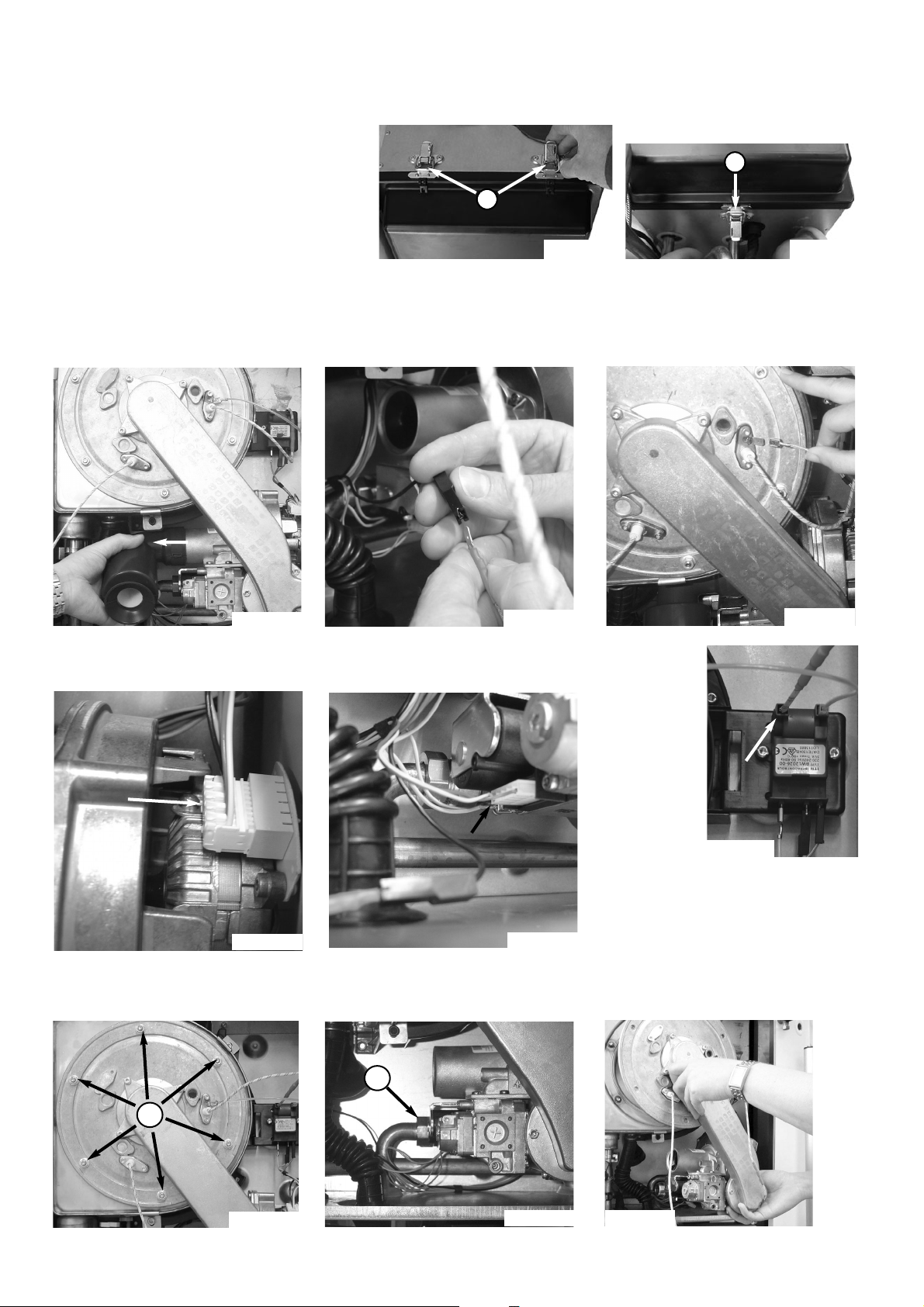
50
18.4.1 Removing the combustion chamber front panel
1.
Carry out step
18.2.1
;
2.
Unlock the three clamp locking bolts “D” and
remove the casing (see Figs. 18.16 and 18.17);
3.
Reassemble in reverse order.
D
Fig. 18.16
D
Fig. 18.17
18.4 Access to the Combustion Chamber
Fig. 18.18
Fig. 18.19
Fig. 18.20
18.4.2 Removing the air gas assembly
1.
Isolate the gas supply to the boiler;
2
. Carry out step 18.2.1;
3.
Remove the silencer (Fig. 18.18)
;
9.
Remove the air gas assembly and
combustion chamber front (Fig. 18.26);
10.
Reassemble in reverse order.
4.
Disconnect the detection electrode
cable (Fig. 18.19);
5.
Remove the earth cable from the
ignition electrode (Fig. 18.20), and
remove the ignition electrode cable
from the ignitor (Fig. 18.21)
6.
Unplug the gas valve and fan connectors (Figs. 18.22 and 18.23);
7.
Unscrew the 6 nuts “E1” on the
combustion chamber (Fig. 18.24);
8.
Unscrew the gas valve nut “E2”
(Fig. 18.25);
Fig. 18.21
Fig. 18.23
Fig. 18.22
Fig. 18.25
Fig. 18.24
Fig. 18.26
E1
E2
Page 51
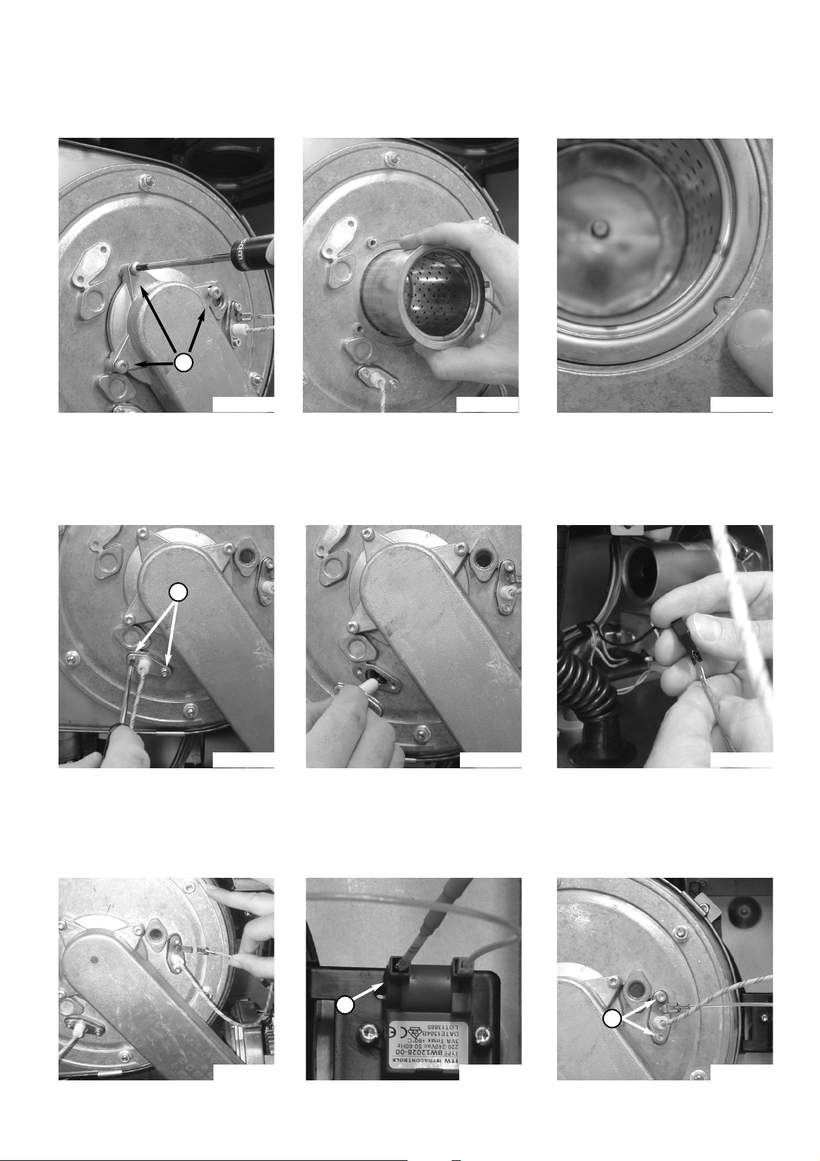
51
F
Fig. 18.27
Fig. 18.28
Fig. 18.29
Fig. 18.30
Fig. 18.31 Fig. 18.32
Fig. 18.33 Fig. 18.34 Fig. 18.35
G
H
I
18.4.3 Removing the burner
18.4.4 Removing the detection electrode
1.
Carry out step
18.2.1
and
18.4.1
;
2.
Remove the 3 screws “F” from the
air/gas manifold (Fig. 18.27)
;
3.
Slide the burner out from the front,
taking care not to damage the
insulation (Fig. 18.28);
4.
Reassemble in reverse order and
checking all seals are undamaged
and the burner is positioned
correctly (Fig. 18.29).
1.
Carry out step
18.2.1
;
2.
Remove the 2 screws “G” from the
electrode manifold (Fig. 18.30)
;
3.
Pull the electrode from the
combustion chamber (Fig. 18.31);
4.
Disconnect the detection electrode
cable (Fig. 18.32).
5.
Reassemble in reverse order.
18.4.5 Removing the ignition electrode
1.
Carry out step
18.2.1
;
2.
Remove the earth cable from the
electrode (Fig. 18.33)
;
3.
Remove the electrode cable “H” from
the ignitor (Fig. 18.34);
4.
Unscrew the 2 screws “I” on the
electrode (Fig. 18.35);
Page 52
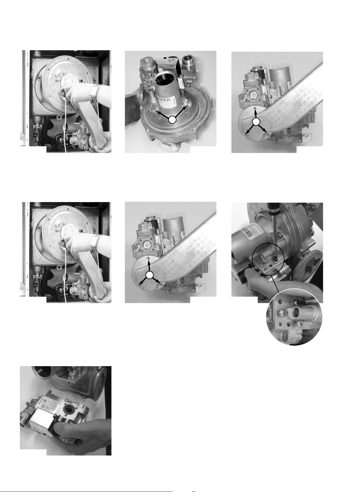
52
Fig. 18.36 Fig. 18.37 Fig. 18.38
Fig. 18.39
Fig. 18.40
Fig. 18.41
Fig. 18.42
J
K
L
18.4.6 Removing the fan
1.
Carry out step
18.2.1
;
2.
Remove the air gas manifiold as in
18.4.2 (Fig. 18.36)
;
3.
Unscrew the two screws from the
venturi “J” and remove with the gas
valve (Fig. 18.37);
4.
Unscrew the three screws “K” on the
air/gas pipe and remove (Fig. 18.38);
5.
Reassemble in reverse order.
18.4.7 Removing the gas valve
1.
Carry out step
18.2.1
;
2.
Remove the air gas manifiold as in
18.4.2
(Fig. 18.39)
;
3.
Unscrew the three screws “L” on the
air/gas pipe and remove (Fig.
18.40);
4.
Unscrew the three screws holding
the gas valve on the venturi (Fig.
18.41);
5.
Remove the gas valve from the
venturi. (Fig. 18.42)
;
6.
Reassemble in reverse order;
7.
The gas valve settings will need to be
adjusted (see Section 14.3 page 28);
8.
Reinstate the gas supply and test for
tightness on reassembly.
Page 53
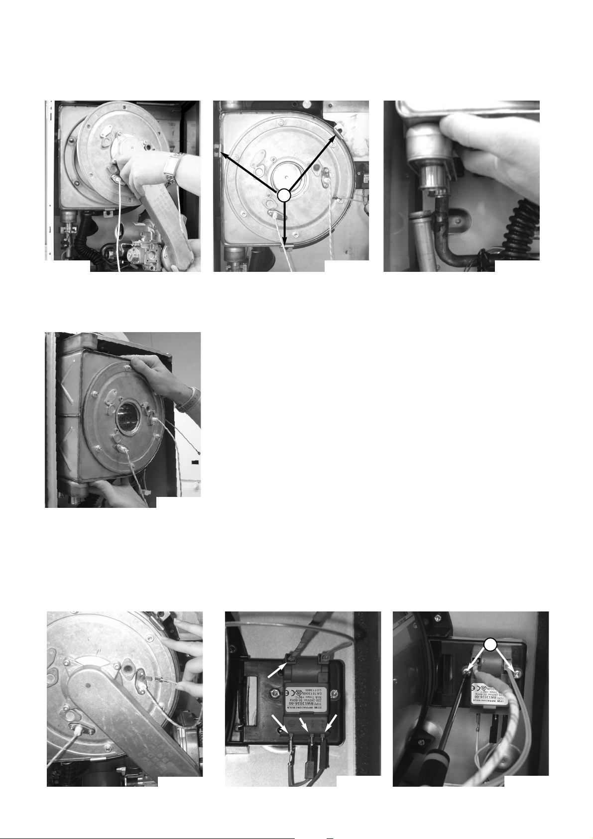
53
Fig. 18.43
Fig. 18.44 Fig. 18.45
Fig. 18.46
Fig. 18.47
Fig. 18.48
Fig. 18.49
M
N
18.4.8 Removing the heat exchanger
1.
Carry out step
18.2.1
;
2.
Remove the air gas manifiold as in
step
18.4.2
(Fig. 18.43)
;
3.
Unscrew the three bolts “M” from the
main heat exchanger (Fig. 18.44);
4.
Remove the flow and return pipes
and the condense drain pipe from
the heat exchanger. (Fig. 18.45);
5.
Remove the heat exchanger from
the boiler by sliding out. (Fig. 18.46);
6.
Reassemble in reverse order.
18.4.9 Removing the spark generator
1.
Carry out step
18.2.1
;
2.
Disconnect the earth cable from the
ignition electrode. (Fig. 18.47)
;
3.
Disconnect the ignition electrode,
live, neutral and earth cables from
the ignitor. (Fig. 18.48);
4.
Remove the two screws “N” from
the ignitor and remove (Fig. 18.49);
5.
Reassemble in reverse order.
Page 54
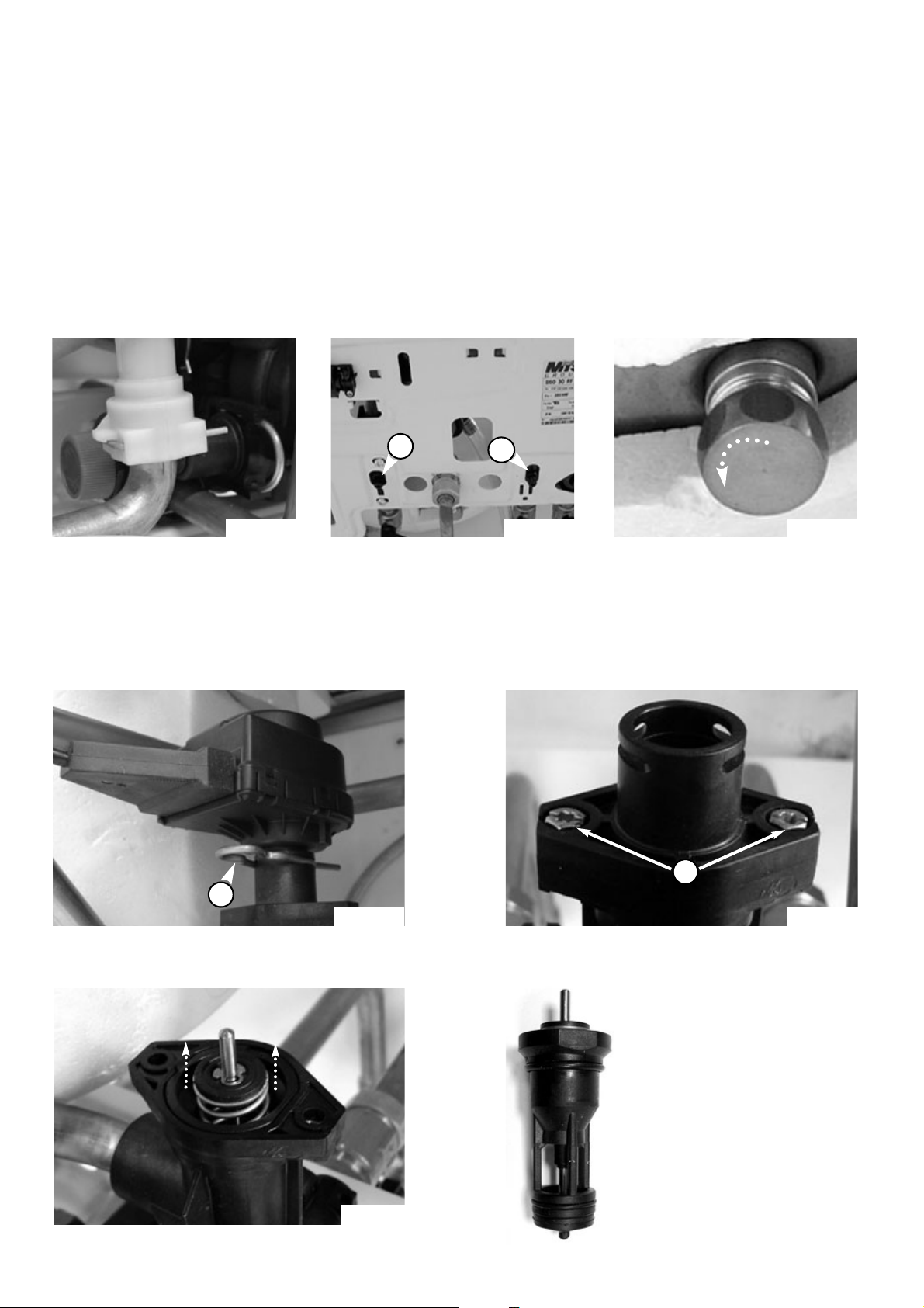
54
18.5 Access to the Water Circuit
Important !
Before any component is removed (except the 3
way valve motor), the boiler must be drained of all water.
Fig. 18.50 Fig. 18.51 Fig. 18.52
18.5.1 Drain down
For the primary circuit :
1.
Carry out steps
18.2.1 & 18.2.2;
2.
Open the pressure relief valve (on the pump) (see Fig.
18.50) or the drain screw “P1” on the right hydraulic block
(see Fig.18.51);
For the D.H.W. circuit :
1.
Close the water inlet tap;
2.
Open a D.H.W. hot water tap;
3.
Open the drain screw “P2” on the boiler (see Fig. 18.51)
To drain the tank more quickly remove the cap on the
tank (see Fig. 18.52);
Important!! Take care when removing the cap to drain the cylinder
P2
P1
1.
Carry out steps
18.2.1
and
18.2.2
;
2.
Remove the clip “Q1” and the three way valve motor
(see Fig.18.53);
Fig. 18.54
Fig. 18.53
Fig. 18.55
18.5.2 Removing the 3 way valve
3.
Remove the two screws “Q2” (see Fig.18.54);
4.
Then pull up the three way valve shutter (see Fig.18.55).
5.
Reassemble in reverse order.
Q1
Q2
Page 55
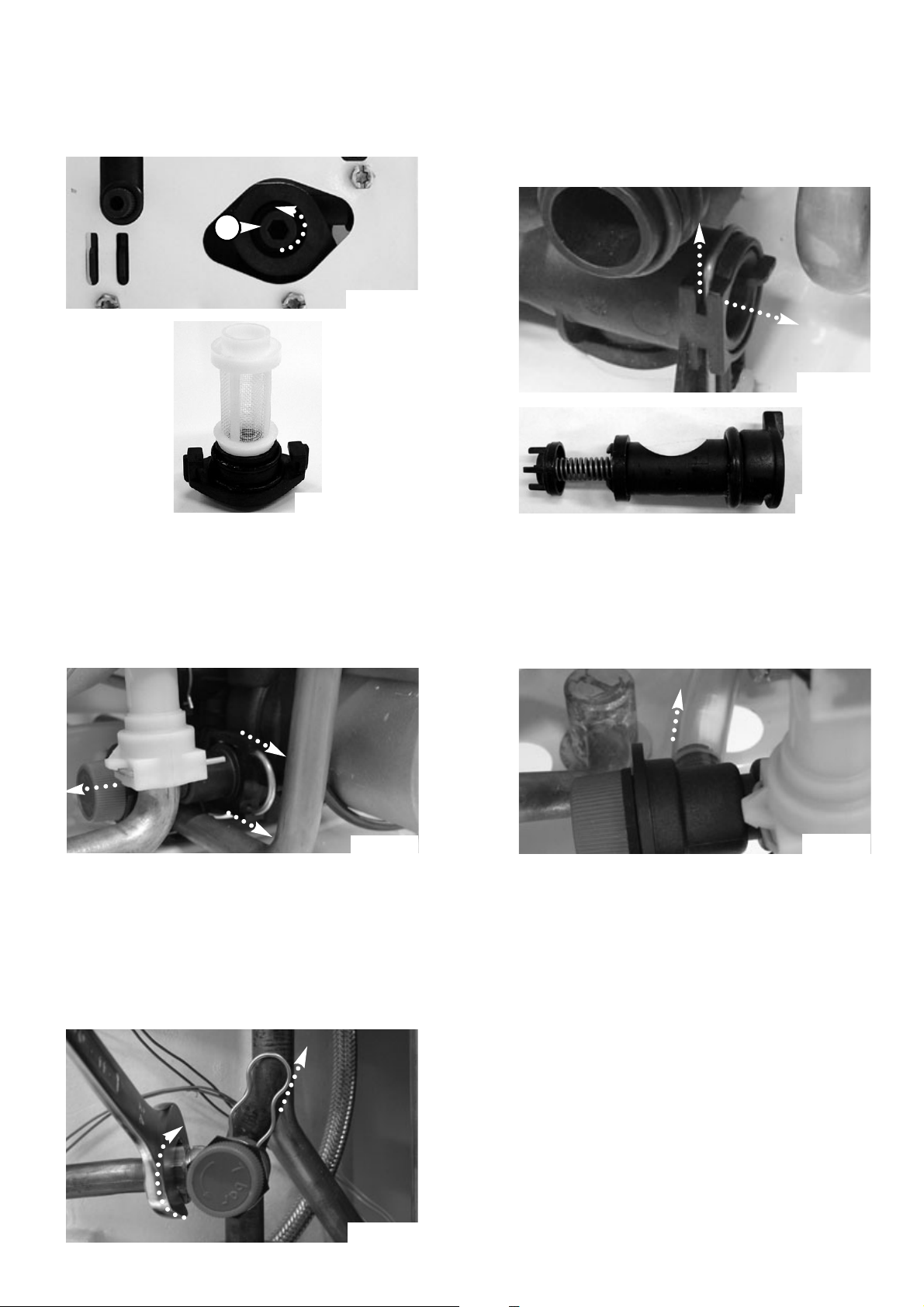
55
18.5.5 Removing the pressure relief valve (3 bar)
1.
Carry out steps
18.2.1
and
18.2.2
;
2.
Remove the clip securing the valve and disconnect
the safety valve outlet (see Fig. 18.60) and pull it
toward the left;
Fig. 18.60
Fig. 18.61
Fig. 18.58
Fig. 18.62
18.5.3 Removing the heating return filter
1.
Unscrew 1/4 ball screw “R” (see Fig. 18.56);
2.
Pull it down (see Fig. 18.57);
3.
Reassemble in reverse order.
Fig. 18.56
R
Fig. 18.57
18.5.4 Removing the by-pass
1.
Carry out steps
18.2.1
and
18.2.2
;
2.
Remove the heating filter as in step
18.6.3
;
3.
Remove the clip and pull out the By-pass (see Fig.
18.58 and 18.59);
4.
Reassemble in reverse order.
Fig. 18.59
18.5.6 Removing the pressure relief valve
(7 bar)
1.
Carry out steps
18.2.1
and
18.2.2
;
2.
Remove the clip securing the valve and unscrew the
nut with a N°24 spanner (see Fg. 18.62);
3.
Reassemble in reverse order.
3.
Disconnect the flexible pipe (see Fig. 18.61);
4.
Reassemble in reverse order.
Page 56
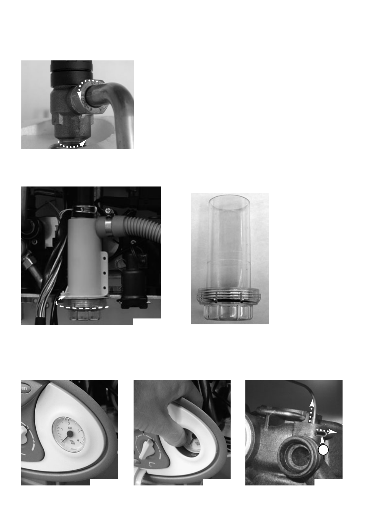
56
18.5.8 Removing & cleaning the condensate trap
1.
Unscrew the cap of the condensate trap (see Fig. 18.64)
2.
Empty the condensate products and rinse the
condensate trap with clean water (see Fig. 18.65)
3.
Reassemble in reverse order and fill the condensate trap
with 1/2 litre of water before restarting the boiler.
Fig. 18.63
18.5.7 Removing the temperature and
pressure relief valve (7 bar)
1.
Unscrew the nut and then unscrew the valve (see Fig. 18.63);
2.
Reassemble in reverse order.
Fig. 18.65
Fig. 18.64
Fig. 18.66 Fig. 18.67 Fig. 18.68
18.5.9 Removing the pressure gauge
1.
Remove the casing as in step
18.2.1
;
2.
Pull the pressure gauge out (see
Fig. 18.67);
3.
Remove the clip “T4” securing
the pressure gauge
(see Fig.
18.68 );
4.
Reassemble in reverse order.
T4
Page 57
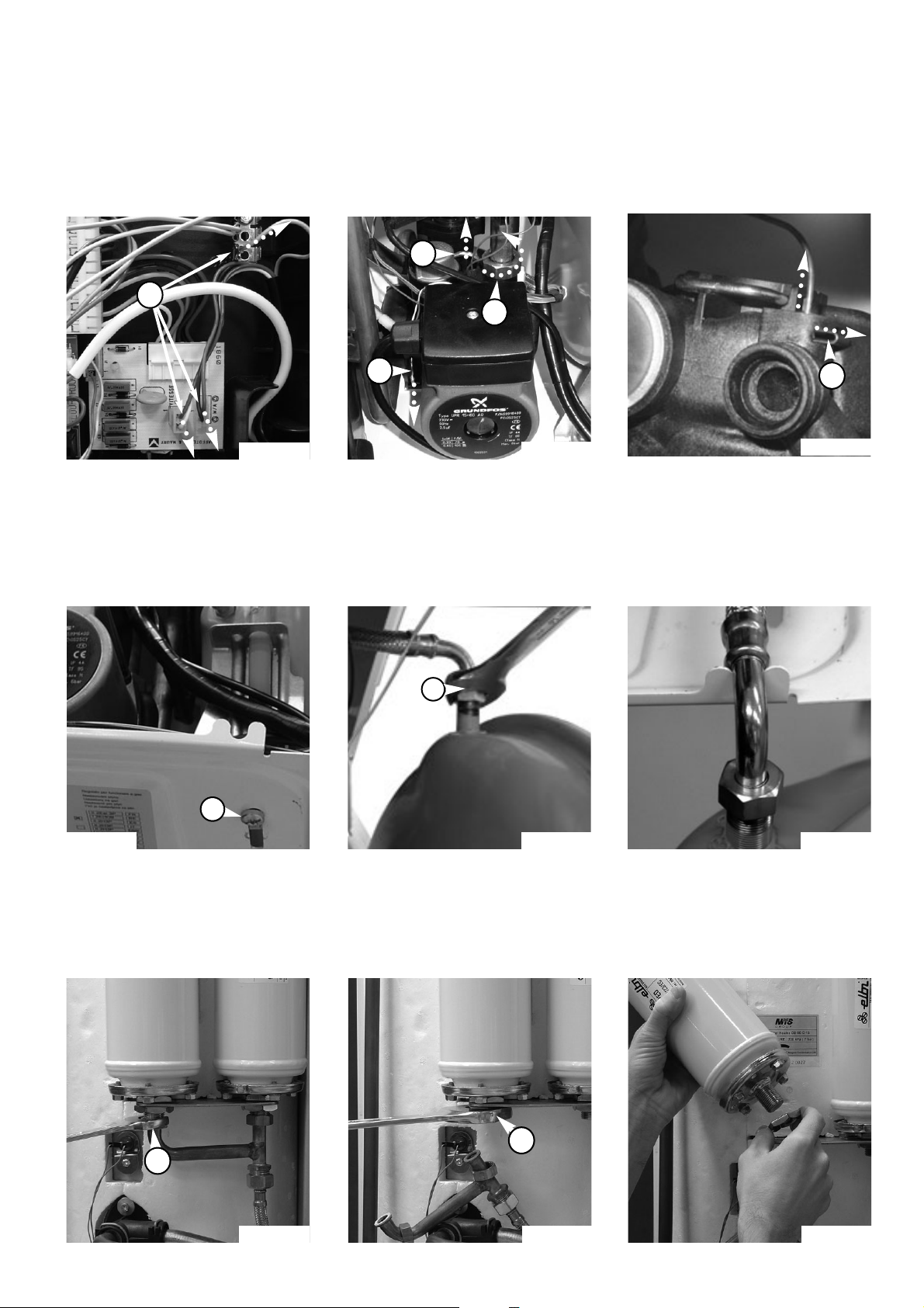
57
18.5.11 Removing the heating expansion vessel
1.
Carry out step
18.2.1
;
2.
Remove the screw “U1” (see Fig.
18.72);
Fig. 18.69
18.5.10 Removing the pump
1.
Carry out step
18.2.1
;
2.
Open the electrical box cover as in
step
18.3.1
(Fig. 18.6);
3.
Remove the pump plug from the
control board and earth plug from
earth socket “T1” (see Fig. 18.69);
4.
Remove the pressure relief valve 3
bar as in step
18.6.5
;
5.
Unscrew the pump nut “T2” and
remove the two clips “T3” on the
pump volute (see Fig. 18.70);
T3
T2
T3
3.
Pull the expansion vessel toward
you and remove the nut “U2” with a
No.17 spanner (see Fig. 18.73);
4.
To ensure the easiest access to the
hydraulic parts, hang the expansion
vessel on the chassis without
removing the nut (see Fig. 18.74);
5.
Reassemble in reverse order.
Fig. 18.72 Fig. 18.73 Fig. 18.74
U1
U2
Fig. 18.75 Fig. 18.76 Fig. 18.77
18.5.12 Removing the D.H.W. expansion vessel
1.
Remove the casing as in step
18.2.1
;
2.
Remove the nut “V1” with a No.24
spanner (see Fig. 18.75);
3.
Remove the “Pal” nut 1/2 “V2” with a
No.34 spanner (see Fig. 18.76);
4.
Pull up the expansion vessel and
unscrew the second “Pal” nut (see
Fig. 18.77);
5.
Reassemble in reverse order.
V2
V1
6.
Pull the pump toward you and
remove the clip “T4” securing the
pressure gauge
(see Fig. 18.71 );
7.
Reassemble in reverse order.
T4
Fig. 18.70
Fig. 18.71
T1
Page 58
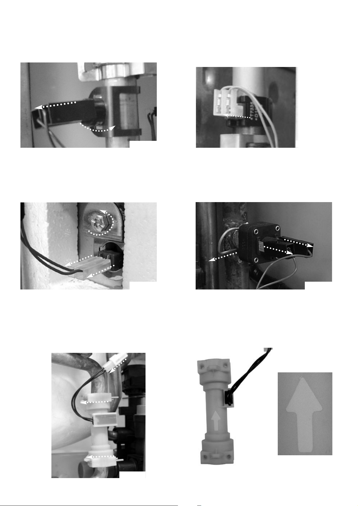
58
18.5.15 Removing the tank temperature sensor
1.
Remove the casing as in step
18.2.1
;
2.
Pull off the NTC connections. Then remove the NTC
from the tank by removing the screws (see Fig.
18.80).
Fig.18.80
18.5.17 Removing the flow switch
1.
Remove the casing as in step
18.2.1
;
2.
Remove electrical connection and the two clips fixing
the flow switch (see Fig. 18.82);
3.
Pull down the lower pipe and remove the flow switch
;
Fig. 18.84
Fig. 18.83
18.5.13 Removing the overheat thermostat
1.
Remove the casing as in step 18.2.1;
2.
Pull off the thermostat connections. Then remove the
thermostat from the pipe by releasing it’s securing
clip (see Fig. 18.78);
18.5.14 Removing the temperature sensors
(N.T.C’s)
1.
Remove the casing as in step 18.2.1;
2.
Pull off the NTC connections. Then remove the NTC
from the pipe by releasing it’s securing clip (see Fig.
18.79).
Fig. 18.78
4.
Reassemble in reverse order, the arrow must be
positioned correctly (see Fig. 18.83 and 18.84);
5.
Reassemble in reverse order
Fig. 18.79
Fig. 18.82
18.5.16 Removing the water pressure gauge
1.
Remove the casing as in step
18.2.1
;
2.
Pull off the connections. Then remove the clip from
the pipe (see Fig. 18.81).
Fig.18.81
Page 59
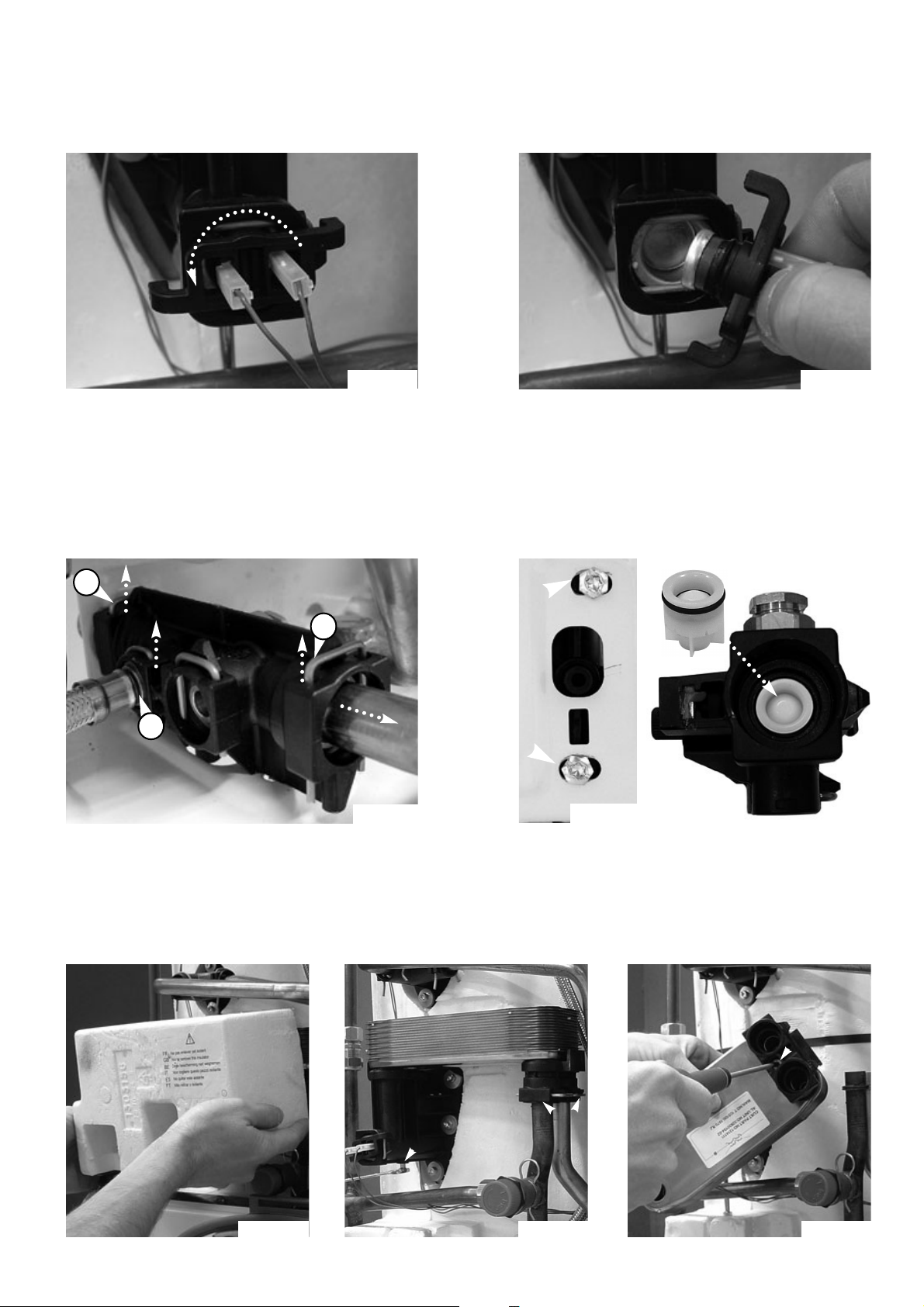
59
18.5.19 Removing the non return valve
1.
Carry out steps 18.2.1 and 18.2.2;
2.
Remove the clip “X1” to liberate the DHW expansion
vessel (see Fig. 18.87);
3.
Remove the two clips “X2” and remove the pipe (see
Fig. 18.87);
Fig. 18.87
Fig. 18.89
Fig. 18.88
4.
Remove the two screws from the bottom of the boiler
(see Fig. 18.88) and pull the block toward you;
5.
Remove the limiter from the block (see Fig.18.89);
6.
Reassemble in reverse order.
X1
X2
X2
18.5.20 Removing the plate heat exchanger
5.
Pull up the exchanger to disengage
it from the pipes and remove the
screw T20 “Y3” (see Fig.18.92);
6.
Reassemble in reverse order.
1.
Carry out step 18.2.1;
2.
Remove the isolating cover by pulling
it toward you (see Fig. 18.90);
3.
Remove the screw “Y1” with a N°8
spanner (see Fig.18.91);
4.
Remove the two clips “Y2” on the
right part (see Fig.18.91);
Fig. 18.90
Fig. 18.91 Fig. 18.92
Y2
Y1
Y3
1.
Carry out step
18.2.1
;
2.
Turn the sensor support anticlockwise to liberate it
(see Fig.18.85);
Fig. 18.86
Fig. 18.85
18.5.18 Removing the DHW temperature sensor
3.
Remove the connections (see Fig.18.86);
4.
Reassemble in reverse order.
Page 60
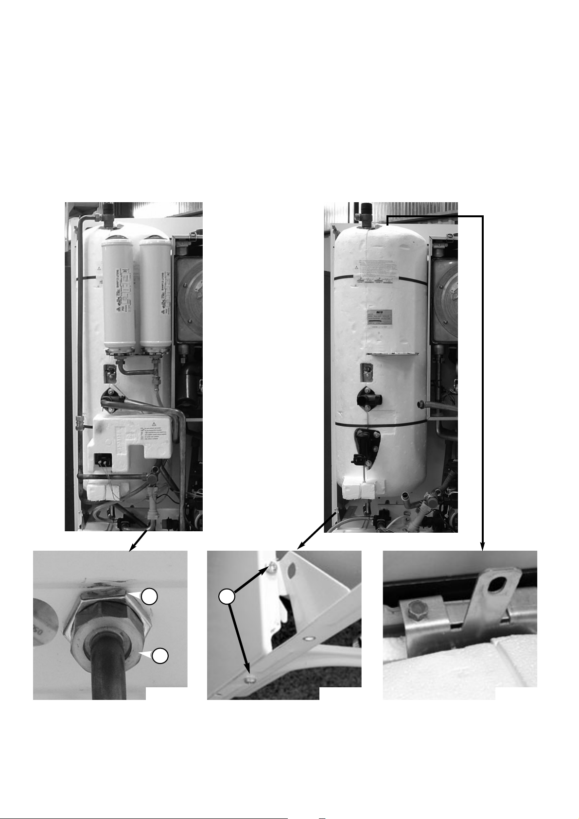
60
18.5.21 Removing the tank
1.
Remove the casing as in steps
18.2.1 and 18.2.2
;
2.
Remove all clips, nuts (No. 24, 25, 30 spanner) and eletrical connections (sensor) from the tank (see Fig. 18.93 & 18.94);
- Temperature and relief valve (7bar) in step 18.5.6 - Pressure relief valve (7bar) in step 18.5.7
- DHW expansion vessel in step 18.5.12 - Tank temperature sensor in step 18.5.15
- DHW temperature sensor in step 18.5.18 - Plate heat exchanger in step 18.5.20
3.
Remove the nut “Z1” (N°30 spanner) and the “Pal” nut “Z2” (N°34 spanner) on the bottom of the boiler to disengage the pipe
between the chassis and the thermal valve (see Fig. 18.95);
4.
Remove the two screws “Z3” on the left side panel (see Fig. 18.96);
5.
Remove the nut (No. 10 spanner ) on the top of the tank (see Fig. 18.97);
6.
Pull up the tank to disengage it, and then toward you to remove it.
7.
Reassemble in reverse order
Fig. 18.94
Fig. 18.97Fig. 18.95
Fig.18. 93
Fig. 18.96
Z1
Z2
Z3
Page 61
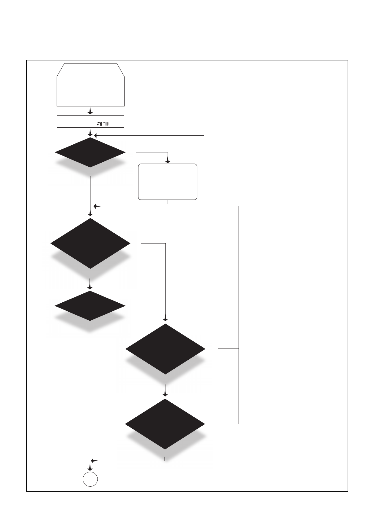
61
PRELIMARY CHECKS
MAKE SURE THAT:
IS
THE POWER
L.E.D.
ON?
E S TAT E
NONO
YESYES
1 - Check the fuses
2 - Check the power supply
cable, plug and outlet
3 - Check/replace the power
supply to the P.C.B.
4 - Check/replace the P.C.B
TURN THE SELECTOR
KNOB TO
TURN THE CH
CONTROL KNOB TO MAX
1 - There is sufficient water in
the system
2 - The gas is turned on
3 - The electrical supply is
turned on
IS DHW BEING
DRAWN
YESYES
YESYES
TURN THE DHW
CONTROL KNOB TO MAX
AND PUSH ON COMFORT
BUTTON
NONO
NONO
NONO
YESYES
IS CLOCK TURNED
ON AND THE ROOM
THERMOSTAT
TURNED UP
NONO
YESYES
FC P012
A
It is possible to detect and correct defects by using the standard fault finding diagrams described in this chapter.
N
OTE:THESE CHECKS ARE NOT EXHAUSTIVE.
19. FAULT FINDING GUIDE (Flow-chart)
Page 62
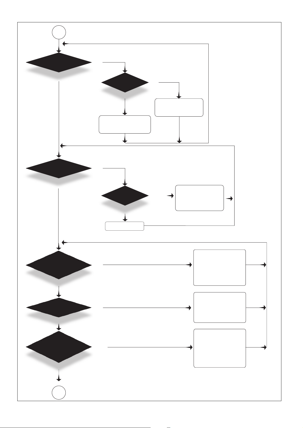
62
NO
NO
YES
NO
YES
YES
YES
NO
YES
NO
YES
NO
NO
YES
A
IS THE PUMP
RUNNING?
IS THE FAN
RUNNING?
YES
YES
NO
POWER TO
THE PUMP?
YES
1 - Check that the pump
is not stuck
2 - Release/replace pump
NO
POWER TO
FAN ?
NO
1 - Check DHW flowswitch
2 - Check pump cable
3 - Check/replace P.C.B.
NO
1 - Check/replace
connection cable
2 - Check/replace P.C.B.
IS SPARK
GENERATION FOR
IGNITION
NORMAL?
YES
IS THE BURNER
ALIGHT?
YES
HAS THE
BOILER SAFETY
SHUTDOWN BEEN
ACTIVATED?
NO
NO
NO
YES
1 - Replace fan
YES
1 - Check/replace ignition
electrode
2 - Check ignition cable
3 - Check spark generator
4 - Check ignition electrode
cable
5 - Check/replace P.C.B.
1 - Check power supply of
gas valve
2 - Check/replace P.C.B.
3 - Check efficiency of
gas valve
4 - Replace gas valve
1 - Check if flame strikes
detection electrode
2 - Check soft-light gas
pressure
3 - Check/replace detection
electrode
4 - Check/replace P.C.B.
B
FC P013
Page 63
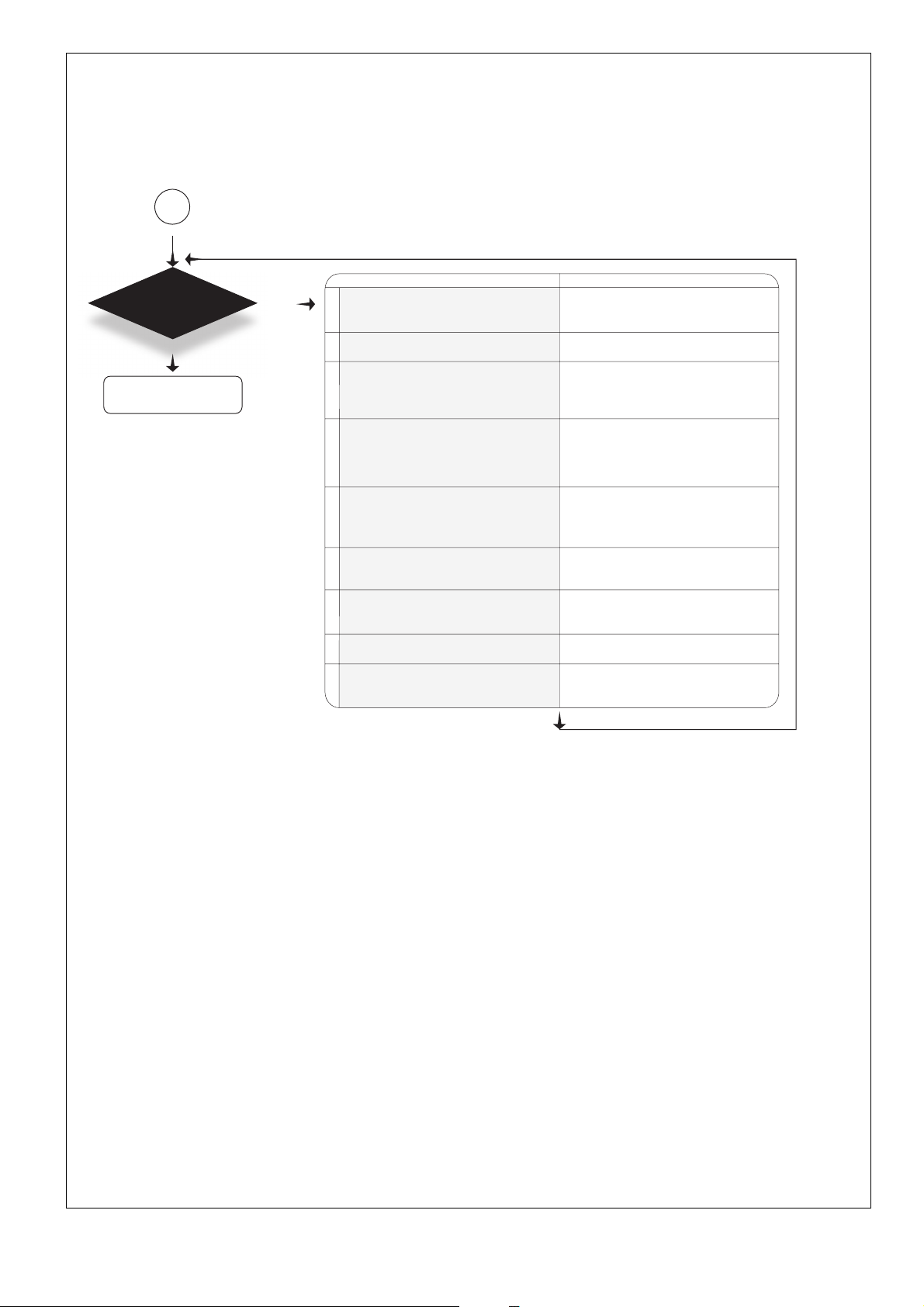
63
NO
YES
1
2
3
4
5
6
7
8
9
B
IS
THERE STILL
A PROBLEM?
NO
NORMAL
OPERATION
YES
Drawing D.H.W:
1
When you turn on a tap
burner switches off
2
Drawing D.H.W:
radiators heat up in summer mode
Drawing D.H.W:
3
insufficient hot water
temperature
4
Drawing D.H.W:
noisy operation
Decrease/increase
5
heating circuit pressure
Repeated shutdowns
6
Repeated intervention of safety thermostat
7
8
When cold water tap turned off, the boiler
ignites
9
Insufficient radiator temperature
FAULTS
POSSIBILE CAUSES
- check temperature probes
- faulty D.H.W. flow switch
- faulty 3-way valve
- check temperature probes
- check gas pressures
- check water flow rate
- primary heat exchanger faulty or
lime-scale deposits
- low heating system water pressure
- check gas pressures
-
check temperature probes
- check for leaks on the heating circuit
- faulty filling-loop
- expansion vessel faulty
- faulty detection electrodes
- check gas settings
- check flame detection electric circuit
-
check temperature probes
- overheat thermostat not calibrated correctly
- air in primary water circuit
- drop in pressure in the water mains, with
consequent water hammer
- check C.H. temperature probe
- check by-pass and pump speed
- check gas pressures
FC P014
Page 64
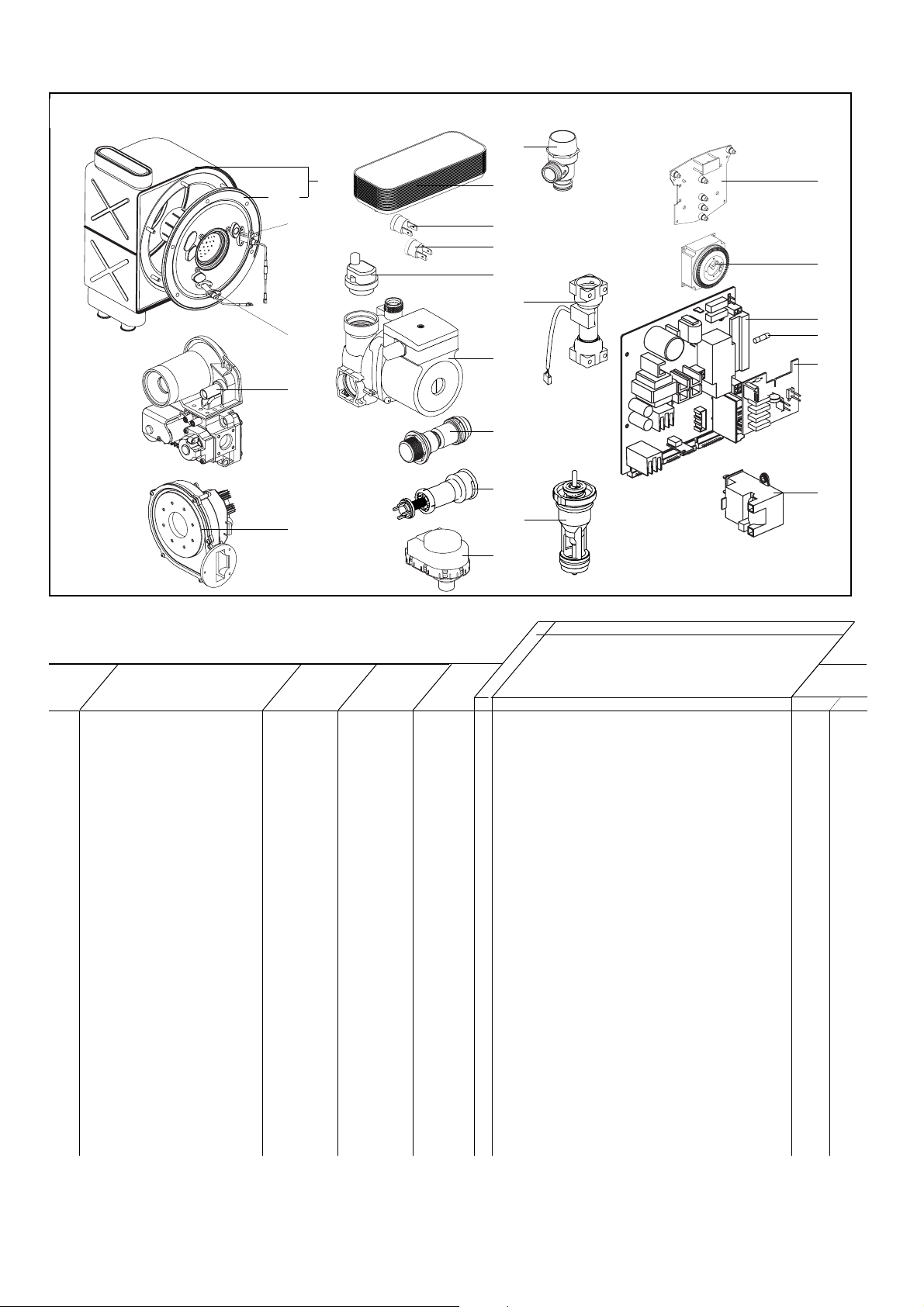
64
20. SHORT SPARES LIST
SHORT LIST
101
102
110
401
111
407
709
721
736
707
722
538
543
502
515
609
603
606
726
649
506
537
531
0101 BURNER 35KW 61314834 .
0102 DOOR ASSY 61313614 .
0110 IGNITION ELECTRODE 61317432 .
0111 IONIZATION ELECTRODE 61317433 .
0401 GAS VALVE 61315410 .
0407 FAN ASSY 61314434 .
0502 MOTOR - THREE-WAY VALVE 61302483 .
0506 VALVE KIT 61303330 .
0515 BY-PASS 61305111 .
0531 AIR SEPARATOR HEAD ASSEMBLY 61304608 .
0537 PRESSURE RELIEF VALVE 61305113 .
0538 PUMP + AIR SEPARATOR 15/50 61301964 .
PUMP + AIR SEPARATOR 15/60 61303461 .
0543 STOPPED WATER THROTTLE 61304982 .
0603 THERMISTOR TEMPERATURE SENSOR 61314258 .
0606 OVERHEAT THERMOSTAT 100°C 61010572 277783 .
0609 WATER/WATER HEAT EXCHANGER 16 61314111 .
0649 PRESSURE RELIEF VALVE 7 BARS 61314112 .
0707 P.C.B. (ACO-MCU) 65103508 .
0709 IGNITER 61002105-20 379075 .
0721 P. C. B. (DISPLAY) 65102235 .
0722 PRINTED CIRCUIT BOARD 61314958 .
0726 FUSE 250V 2A 60054442 264561 .
0736 CLOCK 999599 .
Key N°
Description
Manf. Pt. N°
Other
Type
Manf. date
from to
35
GENUS HE PLUS
Page 65
BENCHMARK No.
FOR ALL BOILERS CONFIRM THE FOLLOWING
BOILER SERIAL No. NOTIFICATION No.
CONTROLS To comply with the Building Regulation, each section must have a tick in one or other of the boxes
THE SYSTEM HAS BEEN FLUSHED IN ACCORDANCE WITH THE BOILER MANUFACTURER’S INSTRUCTIONS?
THE SYSTEM CLEANER USED
THE INHIBITOR USED
FOR THE CENTRAL HEATING MODE, MEASURE & RECORD
GAS RATE m3/hr ft3/hr
BURNER OPERATING PRESSURE ( IF APPLICABLE) N/A mbar
CENTRAL HEATING FLOW TEMPERATURE °C
CENTRAL HEATING RETURN TEMPERATURE °C
FOR COMBINATION BOILERS ONLY
HAS A WATER SCALE REDUCER BEEN FITTED? YES NO
WHAT TYPE OF SCALE REDUCER HAS BEEN FITTED
FOR THE DOMESTIC HOT WATER MODE, MEASURE & RECORD
GAS RATE m3/hr ft3/hr
MAXIMUM BURNER OPERATING PRESSURE (IF APPLICABLE) N/A mbar
COLD WATER INLET TEMPERATURE °C
HOT WATER OUTLET TEMPERATURE °C
WATER FLOW RATE Its/min
FOR CONDENSING BOILERS ONLY CONFIRM THE FOLLOWING
THE CONDENSATE DRAIN HAS BEEN INSTALLED IN ACCORDANCE WITH
THE MANUFACTURER’S INSTRUCTIONS? YES
FOR ALL INSTALLATIONS CONFIRM THE FOLLOWING
THE HEATING AND HOT WATER SYSTEM COMPLIES
WITH CURRENT BUILDING REGULATIONS
THE APPLIANCE AND ASSOCIATED EQUIPMENT HAS BEEN INSTALLED AND COMMISSIONED
IN ACCORDANCE WITH THE MANUFACTURER’S INSTRUCTIONS
IF REQUIRED BY THE MANUFACTURER, HAVE YOU RECORDED A CO/CO2 RATIO READING? N/A YES CO/CO2 RATIO
THE OPERATION OF THE APPLIANCE AND SYSTEM
CONTROLS HAVE BEEN DEMONSTRATED TO THE CUSTOMER
THE MANUFACTURER’S LITERATURE HAS BEEN LEFT WITH THE CUSTOMER
COMMISSIONING ENG’S NAME PRINT CORGI ID N°.
SIGN DATE
TIME & TEMPERATURE CONTROL TO HEATING ROOM T/STAT & PROGRAMMER/TIMER PROGRAMMABLE ROOMSTAT
TIME & TEMPERATURE CONTROL TO HOT WATER CYLINDER T/STAT & PROGRAMMER/TIMER COMBI BOILER
HEATING ZONE VALVES
FITTED
NOT REQUIRED
HOT WATER ZONE VALVES FITTED NOT REQUIRED
THERMOSTATIC RADIATOR VALVES FITTED
AUTOMATIC BYPASS TO SYSTEM FITTED NOT REQUIRED
GAS BOILER COMMISSIONING CHECKLIST
✂
Page 66
SERVICE INTERVAL RECORD
It is recommended that your heating system is serviced regularly
and that you complete the appropriate Service Interval Record Below.
Service Provider. Before completing the appropriate Service Interval Record below, please ensure you have carried out the service
as described in the boiler manufacturer’s instructions. Always use the manufacturer’s specified spare part when replacing all controls
SERVICE 1 DATE
ENGINEER NAME
COMPANY NAME
TEL No.
CORGI ID CARD SERIAL No.
COMMENTS
SIGNATURE
SERVICE 3 DATE
ENGINEER NAME
COMPANY NAME
TEL No.
CORGI ID CARD SERIAL No.
COMMENTS
SIGNATURE
SERVICE 5 DATE
ENGINEER NAME
COMPANY NAME
TEL No.
CORGI ID CARD SERIAL No.
COMMENTS
SIGNATURE
SERVICE 7 DATE
ENGINEER NAME
COMPANY NAME
TEL No.
CORGI ID CARD SERIAL No.
COMMENTS
SIGNATURE
SERVICE 9 DATE
ENGINEER NAME
COMPANY NAME
TEL No.
CORGI ID CARD SERIAL No.
COMMENTS
SIGNATURE
SERVICE 2 DATE
ENGINEER NAME
COMPANY NAME
TEL No.
CORGI ID CARD SERIAL No.
COMMENTS
SIGNATURE
SERVICE 4 DATE
ENGINEER NAME
COMPANY NAME
TEL No.
CORGI ID CARD SERIAL No.
COMMENTS
SIGNATURE
SERVICE 6 DATE
ENGINEER NAME
COMPANY NAME
TEL No.
CORGI ID CARD SERIAL No.
COMMENTS
SIGNATURE
SERVICE 8 DATE
ENGINEER NAME
COMPANY NAME
TEL No.
CORGI ID CARD SERIAL No.
COMMENTS
SIGNATURE
SERVICE 10 DATE
ENGINEER NAME
COMPANY NAME
TEL No.
CORGI ID CARD SERIAL No.
COMMENTS
SIGNATURE
✂
Page 67
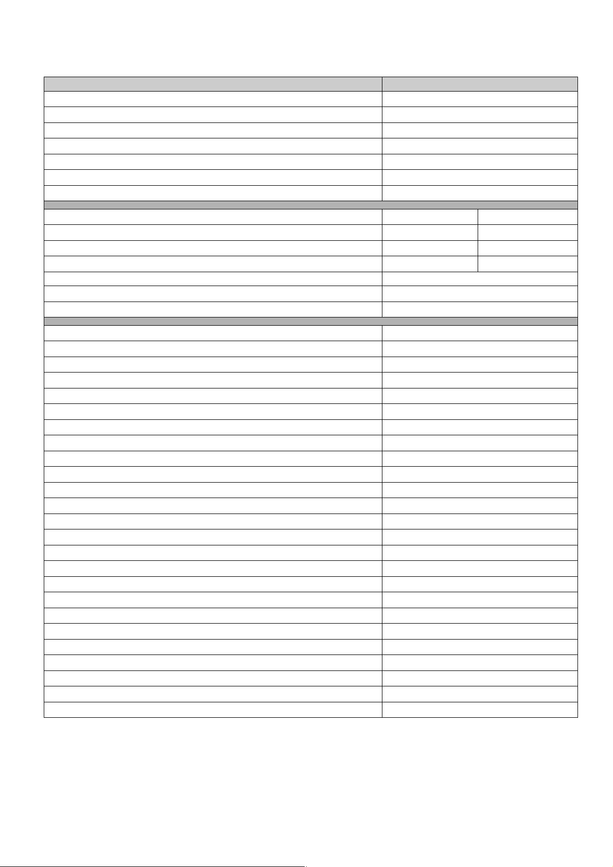
67
Model GENUS HE 35 Plus
CE certificate 1312-BP-4082
Performance category ****
NoX class 5
Category II2H3P
Heating output 80°C/60°C Kw 6 to 30
Heating output 50°C/30°C Kw 7 to 32
Variable hot water power Pn max Kw 35
Nominal gas flow rate (15 °C-1013 mbar) min max
Central Heating & DHW flow rate Qn kW 7 31
G 20 (NG H -Lacq) 34,02 MJ/m3under 20 mbar Vr m3/h 0,74 3,28
G 31 (Propane) 46,4 MJ/kg 37 under mbar Vr kg/h 0,54 2,41
Membrane Diameter (mm)/marking
G 20 mm without
G 31 (propane) mm 5
Adjustable heating outlet temperature: °C 25 to 75 or 42 to 82
Central heating minimum flow rate I/h 300
Central heating circuit maximum pressure Pw max bar 3
Central heating expansion vessel capacity L 7,1
Expansion vessel inflation pressure bar 0,7
Adjustable hot water temperature °C 40 to 70
Stored D.H.W. cylinder capacity L 42
DHW ignition flow rate l/min. 2
DHW specific flow rate (ΔT: 30 K) D I/min. 21,0
DHW start minimum pressure Pw min bar 0,3
Maximum pressure of DHW circuit Pw max bar 7
DHW expansion vessel L 4
Electric voltage 230 volt, single phase - 50 Hz
Electrical input power W 150
Electrical protection IP44
Fresh air flow rate required for combustion V m3h. 40
Mass flow rate for combustion products 15,5
Fume temperature (60-80) °C 67
Fume temperature (30-50) °C 60
CO2 G20 % 9
CO2 G31 % 10
Dimensions Height / Width / Depth (mm) 950 / 595 / 470
Weight kg 59
Flue duct type C13 C33 C43 C53 B23
SEDBUK Band A
This appliance is suitable for Natural gas or LPG. A gas conversion must be made by a competent person.
21. TECHNICAL INFORMATION
Page 68

Commercial subsidiaries: MTS (GB) Limited Professional Team Limited
MTS Building Suites 9 & 10, Plaza 256
Hughenden Avenue Blanchardstown Corporate Park 2
High Wycombe Ballycoolin
Bucks HP13 5FT Dublin 15
Telephone: (01494) 755600 Telephone: (01) 810 3723
Fax: (01494) 459775 Fax: (01) 810 3727
Internet: www.mtsgroup.com/uk Internet: www.mtsgroup.com/ie
Technical Advice: 0870 241 8180 Technical Advice: (01) 437 0121
Customer Service: 0870 600 9888 Customer Service: (01) 437 0121
420010011201 - 07/2007
 Loading...