

Arista DCS-7260QX-64, DCS-7050TX-128, DCS-7050SX2-128, DCS-7250QX-64, DCS-7260CX-64 Quick Start Manual
...
Quick Start Guide
7000 Series 2 RU
Data Center Switches
Arista Networks
www.arista.com
PDOC-00039-10

Headquarters
5453 Great America Parkway
Santa Clara, CA 95054
USA
408 547-5500
www.arista.com
© Copyright 2017 Arista Networks, Inc. The information contained herein is subject to change without notice. Arista Networks
and the Arista logo are trademarks of Arista Networks, Inc in the United States and other countries. Other product or service
names may be trademarks or service marks of others.
ii Quick Start Guide: 7000 Series 2 RU Data Center Switches
Support
408 547-5502
866 476-0000
support@arista.com
Sales
408 547-5501
866 497-0000
sales@arista.com

Overview
1.1 Scope
This guide is intended for properly trained service personnel and technicians who need to install the
following Arista Networks Data Center Switches:
Chapter 1
• DCS-7050SX-128 • DCS-7250QX-64 • DCS-7280CR-48
• DCS-7050TX-128 • DCS-7260QX-64 • DCS-7280CR2-60
• DCS-7050SX2-128 • DCS-7260CX-64 • DCS-7280CR2A-60
• DCS-7050TX2-128 • DCS-7260CX3-64 • DCS-7280CR2K-60
Important! Only qualified personnel should install, service, or replace this equipment.
Seul le personnel qualifié doit installer, service, ou remplacer cet équipement.
1.2 Receiving and Inspecting the Equipment
Upon receiving the switch, inspect the shipping boxes and record any external damage. Retain packing
materials if you suspect that part of the shipment is damaged; the carrier may need to inspect them.
If the boxes were not damaged in transit, unpack them carefully. Ensure that you do not discard any
accessories that may be packaged in the same box as the main unit.
Inspect the packing list and confirm that you received all listed items. Compare the packing list with
your purchase order. Appendix B provides a list of components included with the switch.
1.3 Installation Process
The following tasks are required to install and use the switch:
Step 1 Select and prepare the installation site (Section 2.1).
Step 2 Assemble the installation tools listed in Section 2.2.
Step 3 Attach the mounting brackets and install the switch in an equipment rack (Chapter 3).
Step 4 Connect the switch to the power source and network devices (Chapter 4).
Step 5 Configure the switch (Chapter 5).
Quick Start Guide: 7000 Series 2 RU Data Center Switches 1

Safety Information Chapter 1: Overview
Important! Class 1 Laser Product: This product has provisions to install Class 1 laser transceivers which provide
optical coupling to the communication network. Once a Class 1 laser product is installed, the
equipment is a Class 1 Laser Product (Appareil à Laser de Classe 1). The customer is responsible for
selecting and installing the Class 1 laser transceiver and for insuring that the Class 1 AEL (Allowable
Emission Limit) per EN/IEC 60825, CSA E60825-1, and Code of Federal Regulations 21 CFR 1040 is
not exceeded after the laser transceiver have been installed. Do not install laser products whose class
rating is greater than 1. Refer to all safety instructions that accompanied the transceiver prior to
installation. Only Class 1 laser devices, certified for use in the country of installation by the cognizant
agency are to be utilized in this product.
Appareil à laser de classe 1 Cet appareil comporte des dispositions permettant d'installer des
émetteurs-récepteurs fournissant un couplage optique au réseau de communication. Une fois
l'appareil à laser de classe 1 installé, l'équipement devient un appareil à laser de classe 1. Le client est
responsable du choix et de l'installation de l'émetteur-récepteur à laser de classe 1 et il doit s'assurer
que les limites d'émission admissibles pour la classe 1 régulées par les normes EN/IEC 60825 et
CAN/CSA E60825-1 et par le Code of Federal Regulations 21 CFR 1040 ne soient pas dépassées
après l'installation de l'émetteur-récepteur à laser. N'installez pas d'appareils à laser dont la
classification est supérieure à 1. Avant l'installation, lisez attentivement les instructions de sécurité
fournies avec l'émetteur-récepteur. Seuls les appareils à laser de classe 1 qui ont été certifiés par
l'autorité agréée pour une utilisation dans le pays d'installation peuvent être utilisés dans ce produit.
Important! Ultimate disposal of this product should be in accordance with all applicable laws and regulations.
Élimination définitive de ce produit devrait être en conformité avec toutes les lois et règlements
applicables.
1.4 Safety Information
Refer to the Arista Networks document Safety Information and Translated Safety Warnings available at:
www.arista.com/support/docs/eos
1.5 Obtaining Technical Assistance
Any customer, partner, reseller or distributor holding a valid Arista Service Contract can obtain
technical support in any of the following ways:
• Email: support@arista.com. This is the easiest way to create a new service request.
Include a detailed description of the problem and the output of “show tech-support”.
• Web: www.arista.com/support.
A support case may be created through the support portal on our website. You may also download
the most current software and documentation, as well as view FAQs, Knowledge Base articles,
Security Advisories, and Field Notices.
• Phone: 866-476-0000 or 408-547-5502.
Important! No user serviceable parts inside. Refer all servicing to qualified service personnel.
Aucune pièce réparable par l'utilisateur à l'intérieur. Confiez toute réparation à un technicien qualifié.
2 Quick Start Guide: 7000 Series 2 RU Data Center Switches

Chapter 1: Overview Specifications
1.6 Specifications
Table 1-1 lists the specifications of Arista Data Center switches covered by this guide.
Table 1-1 Switch Specifications
Size (WxHxD) DCS-7050SX-128
Weight DCS-7050SX-128
Operating Temperature
Storage Temperature
Operating Altitude
Relative Humidity
Power Input (AC Power) DCS-7050SX-128 / PWR-500AC
DCS-7050TX-128
DCS-7050SX2-128
DCS-7050TX2-128
DCS-7250QX-64
DCS-7260QX-64
DCS-7260CX-64
DCS-7260CX3-64
DCS-7280CR-48
DCS-7280CR2-60
DCS-7280CR2A-60
DCS-7280CR2K-60
DCS-7050TX-128
DCS-7050SX2-128
DCS-7050TX2-128
DCS-7250QX-64
DCS-7260QX-64
DCS-7260CX-64
DCS-7260CX3-64
DCS-7280CR-48
DCS-7280CR2-60
DCS-7280CR2A-60
DCS-7280CR2K-60
all
all
all
all
DCS-7050SX-128 / PWR-750AC
DCS-7050TX-128 / PWR-745AC
DCS-7050SX2-128 / PWR-500AC
DCS-7050TX2-128 / PWR-745AC
DCS-7250QX-64 / PWR-1100AC
DCS-7260QX-64 / PWR-1100AC
DCS-7260CX-64 / PWR-1900AC
DCS-7260CX3-64 / PWR-745AC
DCS-7260CX3-64 / PWR-1900AC
DCS-7280CR-48 / PWR-1900AC
DCS-7280CR2-60 / PWR-1900AC
DCS-7280CR2A-60 / PWR-1900AC
DCS-7280CR2K-60 / PWR-1900AC
48.3 x 8.8 x 45.9 cm (19 x 3.5 x 18.1 inches)
48.3 x 8.8 x 45.9 cm (19 x 3.5 x 18.1 inches)
48.3 x 8.8 x 45.9 cm (19 x 3.5 x 18.1 inches)
48.3 x 8.8 x 45.9 cm (19 x 3.5 x 18.1 inches)
44.5 x 8.8 x 55.3 cm (19 x 3.5 x 21.8 inches)
44.5 x 8.8 x 45.7 cm (19 x 3.5 x 18.0 inches)
44.5 x 8.8 x 45.7 cm (19 x 3.5 x 18.0 inches)
44.5 x 8.8 x 45.4 cm (19 x 3.5 x 17.9 inches)
44.5 x 8.9 x 56.3 cm (19 x 3.5 x 22.2 inches)
44.5 x 8.8 x 64.0 cm (19 x 3.5 x 25.2 inches)
44.5 x 8.8 x 64.0 cm (19 x 3.5 x 25.2 inches)
44.5 x 8.8 x 64.0 cm (19 x 3.5 x 25.2 inches)
15.1 kg (33 pounds)
15.6 kg (34 pounds)
15.1 kg (33 pounds)
15.6 kg (34 pounds)
19.2 kg (42 pounds)
16.1 kg (35.5 pounds)
21.3 kg (47 pounds)
15.6 kg (34 pounds)
21.2 kg (47 pounds)
24.9 kg (54.8 pounds)
24.9 kg (54.8 pounds)
24.9 kg (54.8 pounds)
0° to 40°C (32° to 104°F)
-25° to 70°C (-13° to 158°F)
0 to 3,000 meters (0 to 10,000 feet)
5to90%
100 - 240 VAC, 5.7-2.4 A, 50/60 Hz
100 - 240 VAC, 5.7-2.4 A, 50/60 Hz
100 - 240 VAC, 10-5 A, 50/60 Hz
100 - 240 VAC, 5.7-2.4 A, 50/60 Hz
100 - 240 VAC, 10-5 A, 50/60 Hz
200 - 240 VAC, 6.5 A, 50/60 Hz
200 - 240 VAC, 6.5 A, 50/60 Hz
200 - 240 VAC, 11.5 A, 50/60 Hz
100 - 240 VAC, 10-5 A, 50/60 Hz
100 - 240 VAC, 10-5 A, 50/60 Hz
200 - 240 VAC, 11.5 A, 50/60 Hz
200 - 240 VAC, 11.5 A, 50/60 Hz
200 - 240 VAC, 11.5 A, 50/60 Hz
200 - 240 VAC, 11.5 A, 50/60 Hz
Quick Start Guide: 7000 Series 2 RU Data Center Switches 3

Specifications Chapter 1: Overview
Table 1-1 Switch Specifications (Continued)
Power Input (DC Power) DCS-7050SX-128 / PWR-500DC
DCS-7050TX-128 /PWR-1900DC
DCS-7250QX-64 / PWR-1900DC
DCS-7260CX-64 / PWR-1900DC
DCS-7260CX3-64 / PWR-1900DC
DCS-7280CR-48 / PWR-1900DC
DCS-7280CR2-60 / PWR-1900DC
DCS-7280CR2A-60 / PWR-1900DC
DCS-7280CR2K-60 / PWR-1900DC
Power Draw
(Typical / Maximum)
DCS-7050SX-128
DCS-7050TX-128
DCS-7050SX2-128
DCS-7050TX2-128
DCS-7250QX-64
DCS-7260QX-64
DCS-7260CX-64
DCS-7260CX3-64
DCS-7280CR-48
DCS-7280CR2-60
DCS-7280CR2A-60
DCS-7280CR2K-60
-48 - 60VDC, 15 A
-48 - 60VDC, 32 A
-48 - 60VDC, 32 A
-48 - 60VDC, 46 A
-48 - 60VDC, 32 A
-48 - 60VDC, 52 A
-48 - 60VDC, 52 A
-48 - 60VDC, 52 A
-48 - 60VDC, 52 A
235 W / 415 W
570 W / 740 W
220 W / 395 W
430 W / 580 W
622 W / 946 W
315 W / 850 W
1672 W / 2090 W
340 W / 660 W
1363 W / 1710 W
1660 W / 1850 W
1760 W / 1950 W
1760 W / 1950 W
4 Quick Start Guide: 7000 Series 2 RU Data Center Switches

Chapter 2
Preparation
2.1 Site Selection
The following criteria should be considered when selecting a site to install the switch:
• Temperature and Ventilation: For proper ventilation, install the switch where there is ample
airflow to the front and back of the switch. The ambient temperature should not go below 0° or
exceed 40°C.
Important! To prevent the switch from overheating, do not operate it in an area where the ambient temperature
exceeds 40°C (104°F).
Pour empêcher l'interrupteur de surchauffe, ne pas utiliser il dans une zone où la température ambiante
est supérieure à 40°C (104°F).
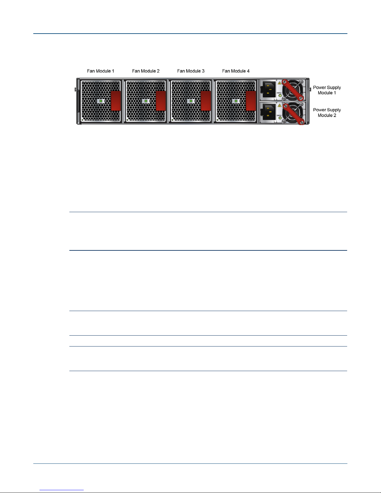
• Airflow Orientation: Determine airflow direction of the four fan modules and two power supply
modules on the rear panel. Fan and power supply module handles indicate airflow direction:
• Blue Handle: Air Inlet module.
• Red Handle: Air Exit module.
Figure 2-1 on page 6 displays fan and power supply module locations on the rear panel. Their red
handles indicate that they are air exit modules. Verify that each module has the same airflow
direction. Base the switch orientation on the airflow direction of the modules to assure the air inlet
is always oriented toward the cool aisle:
• Air Exit modules: orient the rear panel toward the hot aisle.
• Air Inlet modules: orient the rear panel toward the cool aisle.
If the airflow direction is not compatible with the installation site, contact your sales representative
to obtain modules that circulate air in the opposite direction.
Quick Start Guide: 7000 Series 2 RU Data Center Switches 5
Site Selection Chapter 2: Preparation
Figure 2-1: Fan and Power Supply (Air Exit) Modules
• Rack Space: Install the switch in a 19" rack or cabinet. The switch height is 2 RU. The accessory
kit provides mounting brackets for four-post racks. Contact your sales representative to obtain
two-post mounting brackets.
When mounting the switch in a partially filled rack, load the rack from bottom to top, with the
heaviest equipment at the bottom. Load the switch at the bottom if it is the only item in the rack.
• Power Requirements: Power requirements vary by switch and power supply model. Refer to
Table 1-1 for information regarding your specific system.
Two circuits provide redundancy protection. Section 4.1 describes power cable requirements.
Important! The power input plug-socket combination must be accessible at all times; it provides the primary
method of disconnecting power from the system.
La combinaison de la puissance-prise d'entrée doit être accessible en tout temps ; Il fournit le principal
moyen de coupure d'alimentation du système.
• Other Requirements: Select a site where liquids or objects cannot fall onto the equipment and
foreign objects are not drawn into the ventilation holes. Verify these guidelines are met:
• Clearance areas to the front and rear panels allow for unrestricted cabling.
• All front and rear panel indicators can be easily read.
• Power cords can reach from the power outlet to the connector on the rear panel.
Important! All power connections must be removed to de-energize the unit.
Toutes les connexions d'alimentation doivent être enlevées pour hors tension l'appareil.
Important! This unit is intended for installation in restricted access areas.
Cet appareil est prévu pour une installation dans les zones d'accès restreintes.
6 Quick Start Guide: 7000 Series 2 RU Data Center Switches

Chapter 2: Preparation Tools and Parts Required for Installation
2.2 Tools and Parts Required for Installation
The following tools and equipment are required to install the switch:
Two-Post Rack
• Screws or rack mounting nuts and bolts.
• Screwdriver
Four-Post Rack (Toolless)
No additional equipment required.
Accessory kit does not include screws for attaching the switch to the equipment rack. When installing
the switch into an equipment rack with unthreaded post holes, nuts are also required to secure the
switch to the rack posts.
2.3 Electrostatic Discharge (ESD) Precautions
Observe these guidelines to avoid ESD damage when installing or servicing the switch.
• Assemble or disassemble equipment only in a static-free work area.
• Use a conductive work surface (such as an anti-static mat) to dissipate static charge.
• Wear a conductive wrist strap to dissipate static charge accumulation.
• Minimize handling of assemblies and components.
• Keep replacement parts in their original static-free packaging.
• Remove all plastic, foam, vinyl, paper, and other static-generating materials from the work area.
• Use tools that do not create ESD.
Quick Start Guide: 7000 Series 2 RU Data Center Switches 7

Electrostatic Discharge (ESD) Precautions Chapter 2: Preparation
8 Quick Start Guide: 7000 Series 2 RU Data Center Switches
Chapter 3
Rack Mounting the Switch
Important! The rack mounting procedure is identical for all switches covered by this guide. Illustrations in this
chapter depict the mounting of a DCS-7050SX-128 switch.
Les procédure de montage du bâti est identique pour tous les commutateurs visés par ce guide.
Illustrations dans ce chapitre montrent le montage d'un interrupteur de DCS-7050SX-128.
• Section 3.1 provides instructions for mounting the switch in a two-post rack.
• Section 3.2 provides instructions for mounting the switch in a four-post rack.
After completing the instructions for your rack type, proceed to Chapter 4.
3.1 Two-Post Rack Mount
To mount the switch onto a two-post rack, assemble the mounting brackets to the chassis, then attach
the brackets to the rack posts. Two-post accessory kits includes 2 three-hole mounting brackets.
Each chassis side has attachment pins that align with bracket holes; the number of pins (six or seven)
varies by switch model. Pin orientation is symmetric and equidistant, supporting bracket placement
where the flange is either flush with the front and rear panels, or not flush with the panels. Each bracket
hole includes a key-opening for placing the bracket flush with the chassis and then locking it into place.
Important! Attachment pins must engage all three upper bracket holes.
Goupilles de fixation doivent s’engager tous les trois trous de la bride supérieure..
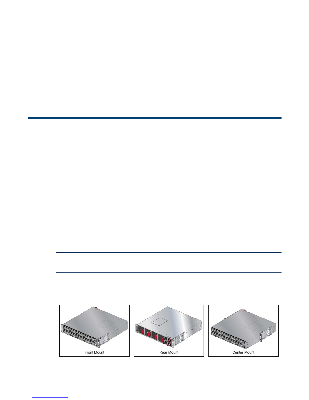
Figure 3-1 displays proper bracket mount configuration examples. Figure 3-2 on page 10 displays
improper bracket mount configuration examples.
Figure 3-1: Bracket Mount Examples for Two-Post Rack Mount
Quick Start Guide: 7000 Series 2 RU Data Center Switches 9
Two-Post Rack Mount Chapter 3: Rack Mounting the Switch
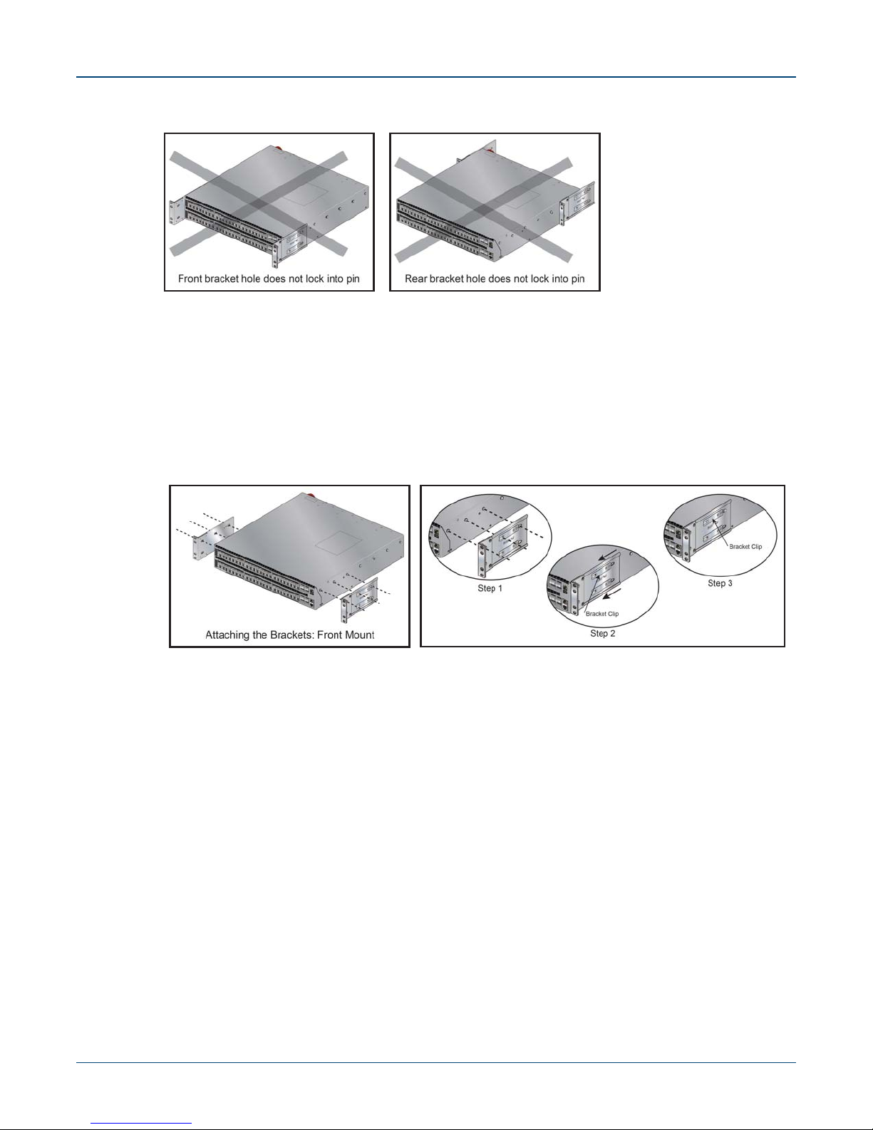
Figure 3-2: Improper Bracket Mount Examples for Two-Post Rack Mount
3.1.1 Attaching Mounting Brackets to the Chassis
This procedure attaches mounting brackets to the switch chassis (Figure 3-3).
Step 1 Align the mounting brackets with the attachment pins to obtain the desired mounting position.
Step 2 Place the bracket flush on the chassis with attachment pins protruding through key-openings.
Step 3 Slide the bracket toward the front flange until the bracket clip locks with an audible click.
Figure 3-3: Attaching the Mounting Brackets to the Switch Chassis
To remove the mounting bracket from the chassis, lift the front edge of the mounting bracket clip
with a flathead screwdriver and slide the bracket away from the front flange (opposite from the
installation direction).
3.1.2 Inserting the Switch into the Rack
This procedure attaches the switch to the rack (Figure 3-4 on page 11).
Step 1 Lift the chassis into the rack. Position the flanges against the rack posts.
10 Quick Start Guide: 7000 Series 2 RU Data Center Switches

Chapter 3: Rack Mounting the Switch Four-Post Rack Mount
Figure 3-4: Inserting the Switch into the Rack
Step 2 Select mounting screws that fit your equipment rack.
Step 3 Attach the bracket flanges to the rack posts.
After completing the two-post rack mount, proceed to Chapter 4.
3.2 Four-Post Rack Mount
The switch is mounted onto a four-post rack by assembling two rails onto the rear posts, sliding the
switch onto the rails, then securing the switch to the front posts.
The installation kit provides two bracket-rail assemblies. The following four-post mounting parts are
extracted from each assembly:
• Six-hole mounting bracket
• Rail
Each chassis side has attachment pins that align with bracket holes; the number of pins (six or seven)
varies by switch model. Pin orientation is symmetric and equidistant, supporting bracket placement
where the flange is either flush with the front and rear panels, or not flush with the panels. Each bracket
hole includes a key-opening for placing the bracket flush with the chassis and then locking it into place.
Important! Attachment pins must engage all six bracket holes.
Goupilles de fixation doivent s’engager tous les trous de support six.
Figure 3-5 on page 12 displays proper bracket mount configuration examples. Figure 3-6 on page 12
displays an improper bracket mount configuration examples.
Quick Start Guide: 7000 Series 2 RU Data Center Switches 11
Four-Post Rack Mount Chapter 3: Rack Mounting the Switch
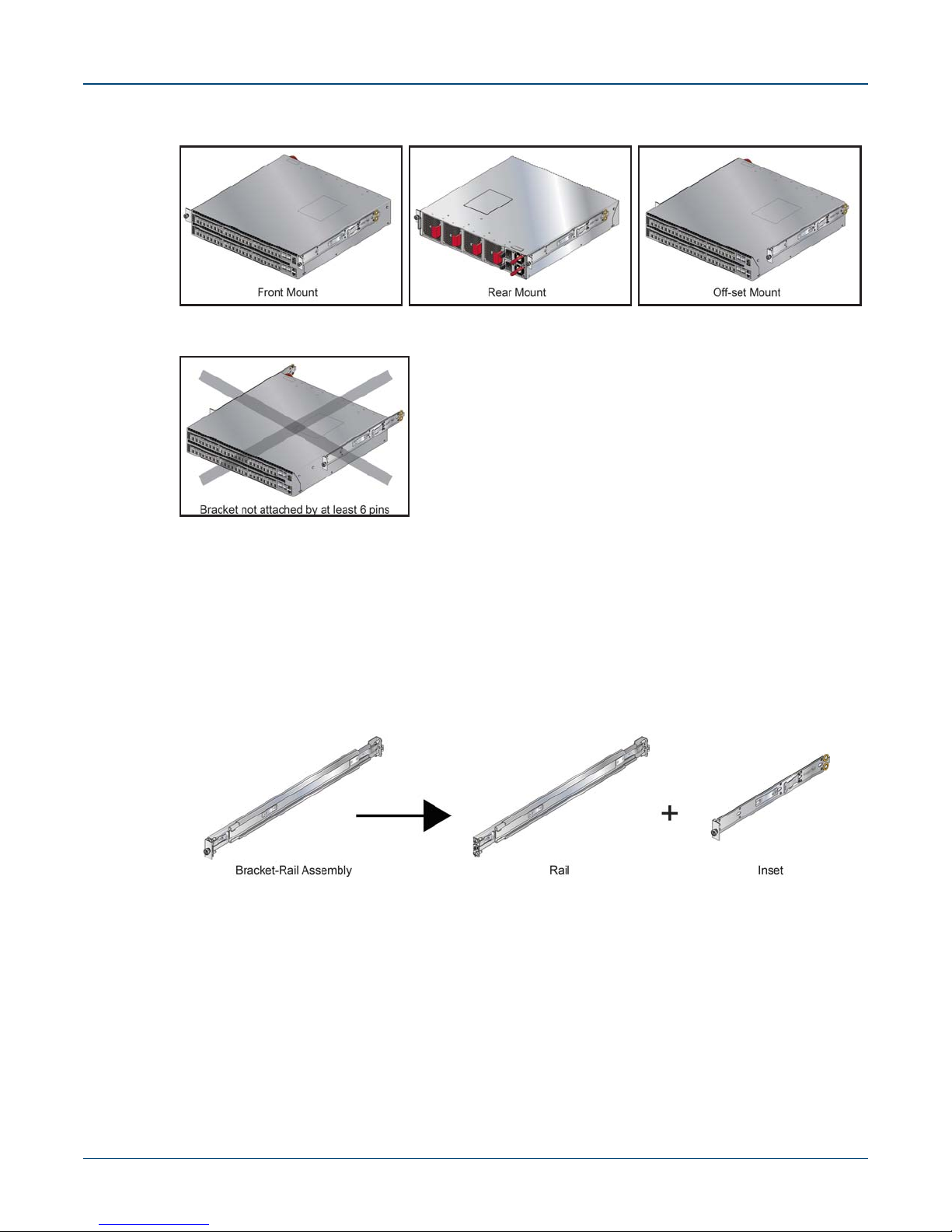
Figure 3-5: Bracket Mount Examples for Four-Post Rack Mount
Figure 3-6: Improper Bracket Mount Example for Four-Post Rack Mount
Off-set mount is always an improper bracket mount configuration on switches that have six attachment
pins on each side.
3.2.1 Extracting the Brackets and the Rails
Figure 3-7 displays a bracket-rail assembly and the component pieces (bracket and rail) that are
extracted from the assembly. Each assembly must be separated into its component pieces before
mounting the switch into a four-post rack. The two assemblies supplied with the switch are identical.
Figure 3-7: Bracket-Rail Assembly – Before and After Extraction
This procedure separates a bracket-rail assembly into its component pieces.
Step 1 Grip the rail with your right hand, as shown in Figure 3-8-left. Pull the bracket flange away from
the rail flange with your left hand until the bracket clip catches on the rail (Figure 3-8-Right).
If the bracket flange resists initially, verify the thumb screw on the bracket flange is not attached
to the rail flange.
12 Quick Start Guide: 7000 Series 2 RU Data Center Switches
 Loading...