

Page 1

Quick Start Guide
7280 Series 1 RU (Gen 3)
Data Center Switches
Arista Networks
www.arista.com
PDOC-00144-04
Page 2

Headquarters
5453 Great America Parkway
Santa Clara, CA 95054
USA
+1 408 547-5500
www.arista.com
© Copyright 2021 Arista Networks, Inc. The information contained herein is subject to change without notice. Arista Networks
and the Arista logo are trademarks of Arista Networks, Inc in the United States and other countries. Other product or service
names may be trademarks or service marks of others.
ii Quick Start Guide: 7280 Series 1 RU-Gen 3 Data Center Switches
Support
+1 408 547-5502
+1 866 476-0000
Sales
+1 408 547-5501
+1 866 497-0000
Page 3

Table of Contents
Chapter 1 Overview.............................................................................................................1
1.1 Scope...................................................................................................................................................... 1
1.2 Receiving and Inspecting the Equipment................................................................................................ 1
1.3 Installation Process................................................................................................................................. 1
1.4 Safety Information................................................................................................................................... 2
1.5 Obtaining Technical Assistance.............................................................................................................. 2
1.6 Specifications.......................................................................................................................................... 3
Chapter 2 Preparation.........................................................................................................7
2.1 Site Selection.......................................................................................................................................... 7
2.2 Tools and Parts Required for Installation................................................................................................ 8
2.3 Electrostatic Discharge (ESD) Precautions ............................................................................................ 9
Chapter 3 Rack Mounting the Switch ..............................................................................11
3.1 Two-Post Rack Mount........................................................................................................................... 11
3.1.1 Attaching Mounting Brackets to the Chassis ........................................................................... 12
3.1.2 Inserting the Switch into the Rack............................................................................................ 13
3.2 Four-Post Rack Mount .......................................................................................................................... 13
3.2.1 Attaching Mounting Brackets to the Chassis ........................................................................... 14
3.2.2 Assembling the Rails onto the Equipment Rack ...................................................................... 15
3.2.3 Attaching the Switch to the Rack ............................................................................................. 17
Chapter 4 Cabling the Switch...........................................................................................19
4.1 Grounding the Switch ........................................................................................................................... 19
4.2 Grounding Adapter Assembly (DCS-7280CR3-32P4).......................................................................... 20
4.3 Connecting Power Cables .................................................................................................................... 21
4.3.1 AC Power Supplies .................................................................................................................. 22
4.3.2 DC Power Supplies.................................................................................................................. 22
4.4 Connecting Serial and Management Cables ........................................................................................ 25
Chapter 5 Configuring the Switch ...................................................................................29
Appendix A Status Indicators...........................................................................................31
A.1 Front Indicators..................................................................................................................................... 31
A.1.1 Switch Indicators...................................................................................................................... 31
A.1.2 Port Indicators.......................................................................................................................... 32
Quick Start Guide: 7280 Series 1 RU-Gen 3 Data Center Switches iii
Page 4

A.2 Rear Status Indicators .......................................................................................................................... 33
Appendix B Parts List........................................................................................................37
B.1 Rack Mount Parts ................................................................................................................................. 37
B.1.1 Four-Post Rack Mount Parts....................................................................................................37
B.1.2 Two-Post Rack Mount Parts .................................................................................................... 38
B.2 Cables................................................................................................................................................... 38
B.3 Ground Extender Kit (Optional)............................................................................................................. 38
Appendix C Front Panel ....................................................................................................39
Appendix D Rear Panel .....................................................................................................47
Appendix E Maintenance and Field Replacement ..........................................................49
E.1 Considerations...................................................................................................................................... 49
E.2 Power Supplies..................................................................................................................................... 49
E.2.1 Removing a Power Supply.......................................................................................................49
E.2.2 Installing a Power Supply......................................................................................................... 50
E.3 Fan Modules ......................................................................................................................................... 50
E.3.1 Removing a Fan Module.......................................................................................................... 50
E.3.2 Installing a Fan Module............................................................................................................ 51
Appendix F Regulatory Model Numbers .........................................................................53
Appendix G Taiwan RoHS Information ............................................................................55
iv Quick Start Guide: 7280 Series 1 RU-Gen 3 Data Center Switches
Page 5

Overview
1.1 Scope
This guide is intended for properly trained service personnel and technicians who need to install the
following Arista Networks Data Center Switches:
DCS-7280SE-64 DCS-7280SE-68 DCS-7280SE-72 DCS-7280QR-C36
DCS-7280TR-48C6 DCS-7280SR2A-48YC6 DCS-7280TRA-48C6 DCS-7280QRA-C36S
DCS-7280SRAM-48C6 DCS-7280SR-48C6 DCS-7280SR2-48YC6 DCS-7280SRA-48C6
DCS-7280SR2K-48C6 DCS-7280SRM-40CX2 DCS-7280CR3-32D4 DCS-7280CR3-32P4
DCS-7280DR3-24 DCS-7280PR3-24 DCS-7280SR3-48YC8 DCS-7280SR3K-48YC8
DCS-7280CR3K-32D4 DCS-7280CR3K-32P4 DCS-7280DR3K-24 DCS-7280PR3K-24
Chapter 1
Important! Only qualified personnel should install, service, or replace this equipment.
Seul le personnel qualifié doit installer, service, ou remplacer cet équipement.
1.2 Receiving and Inspecting the Equipment
Upon receiving the switch, inspect the shipping boxes and record any external damage. Retain packing
materials if you suspect that part of the shipment is damaged; the carrier may need to inspect them.
If the boxes were not damaged in transit, unpack them carefully. Ensure that you do not discard any
accessories that may be packaged in the same box as the main unit.
Inspect the packing list and confirm that you received all listed items. Compare the packing list with
your purchase order. Appendix B provides a list of components included with the switch.
1.3 Installation Process
The following tasks are required to install and use the switch:
Step 1 Select and prepare the installation site (Section 2.1).
Step 2 Assemble the installation tools (Section 2.2).
Step 3 Attach the mounting brackets and install the switch in an equipment rack (Chapter 3).
Step 4 Connect the switch to the power source and network devices (Chapter 4).
Quick Start Guide: 7280 Series 1 RU-Gen 3 Data Center Switches 1
Page 6

Safety Information Chapter 1: Overview
Step 5 Configure the switch (Chapter 5).
Important! Class 1 Laser Product: This product has provisions to install Class 1 laser transceivers which provide
optical coupling to the communication network. Once a Class 1 laser product is installed, the
equipment is a Class 1 Laser Product (Appareil à Laser de Classe 1). The customer is responsible for
selecting and installing the Class 1 laser transceiver and for insuring that the Class 1 AEL (Allowable
Emission Limit) per EN/IEC 60825, CSA E60825-1, and Code of Federal Regulations 21 CFR 1040 is
not exceeded after the laser transceiver have been installed. Do not install laser products whose class
rating is greater than 1. Refer to all safety instructions that accompanied the transceiver prior to
installation. Only Class 1 laser devices, certified for use in the country of installation by the cognizant
agency are to be utilized in this product.
Produit Laser de classe 1: Ce produit a des dispositions pour installer des émetteurs-récepteurs de
laser de classe 1 qui offre de couplage au réseau de communication optique.Une fois un produit laser
de classe 1 est installé, l'équipement est un produit Laser de classe 1 (Appareil à Laser de Classe 1).Le
client est responsable pour sélectionner et installer l'émetteur/récepteur de laser de classe 1 et pour
assurer que la classe 1 AEL (limite d'émission admissible) par EN/IEC 6-825, CSA E60825-1, et Code
des règlements fédéraux 21 CFR 1040 ne soit pas dépassée après avoir installé l'émetteur/récepteur
de laser. Ne pas installer des appareils à laser dont la cote de classe est supérieure à 1.Voir toutes les
consignes de sécurité qui ont accompagné l'émetteur-récepteur avant l'installation. Seuls appareils
laser de classe 1 certifiés pour une utilisation dans le pays d’installation par l’organisme compétent
doivent être utilisées dans ce produit.Ultimate disposal of this product should be in accordance with all
applicable laws and regulations.
Important! Ultimate disposal of this product should be handled in accordance with all national laws and
regulations.
Aucune pièce réparable par l'utilisateur à l'intérieur. Confiez toute réparation à un technicien qualifié.
1.4 Safety Information
Refer to the Arista Networks document Safety Information and Translated Safety Warnings available at:
https://www.arista.com/en/support/product-documentation
1.5 Obtaining Technical Assistance
Any customer, partner, reseller or distributor holding a valid Arista Service Contract can obtain
technical support in any of the following ways:
• Email: [email protected]. This is the easiest way to create a new service request.
Include a detailed description of the problem and the output of “show tech-support”.
• Web: https://www.arista.com/en/support
A support case may be created through the support portal on our website. You may also download
the most current software and documentation, as well as view FAQs, Knowledge Base articles,
Security Advisories, and Field Notices.
• Phone: +1 866-476-0000 or +1 408-547-5502.
Important! No user serviceable parts inside. Refer all servicing to qualified service personnel.
Aucune pièce réparable par l'utilisateur à l'intérieur. Confiez toute réparation à un technicien qualifié.
2 Quick Start Guide: 7280 Series 1 RU-Gen 3 Data Center Switches
Page 7
Chapter 1: Overview Specifications
1.6 Specifications
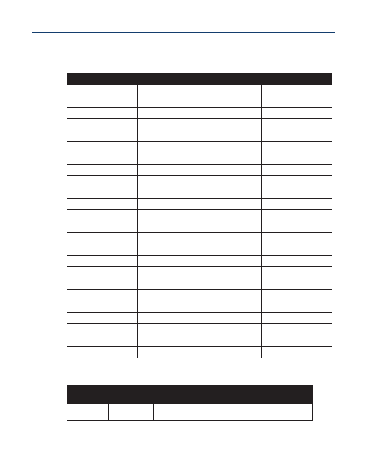
Table 1-1 Switch Specifications (Dimensions and Weights)
Switch Size (WxHxD) Weight
DCS-7280SE-64 48.3 x 4.4 x 52.3 cm (19 x 1.75 x 20.6 inches) 10.0 kg (22.0 lbs.)
DCS-7280SE-68 48.3 x 4.4 x 52.3 cm (19 x 1.75 x 20.6 inches) 10.1 kg (22.3 lbs.)
DCS-7280SE-72 48.3 x 4.4 x 52.3 cm (19 x 1.75 x 20.6 inches) 10.2 kg (22.5 lbs.)
DCS-7280QR-C36 48.3 x 4.4 x 52.3 cm (19 x 1.75 x 20.6 inches) 9.7 kg (21.4 lbs.)
DCS-7280TR-48C6 48.3 x 4.4 x 40.6 cm (19 x 1.75 x 16 inches) 10.1 kg (22.3 lbs.)
DCS-7280SR2A-48YC6 48.3 x 4.4 x 52.3 cm (19 x 1.75 x 20.6 inches) 10.4 kg (22.9 lbs.)
DCS-7280TRA-48C6 48.3 x 4.4 x 40.6 cm (19 x 1.75 x 16 inches) 10.1 kg (22.3 lbs.)
DCS-7280QRA-C36S 48.3 x 4.4 x 52.3 cm (19 x 1.75 x 20.6 inches) 10.7 kg (23.6 lbs.)
DCS-7280SRAM-48C6 48.3 x 4.4 x 40.6 cm (19 x 1.75 x 16 inches) 9.0 kg (20.0 lbs.)
DCS-7280SR-48C6 48.3 x 4.4 x 40.6 cm (19 x 1.75 x 16 inches) 10.0 kg (22.0 lbs.)
DCS-7280SR2-48YC6 48.3 x 4.4 x 52.3 cm (19 x 1.75 x 20.6 inches) 10.4 kg (22.9 lbs.)
DCS-7280SRA-48C6 48.3 x 4.4 x 40.6 cm (19 x 1.75 x 16 inches) 8.6 kg (19.0 lbs.)
DCS-7280SR2K-48C6 48.3 x 4.4 x 40.6 cm (19 x 1.75 x 16 inches) 9.0 kg (20.0 lbs.)
DCS-7280SRM-40CX2 44.0 x 4.4 x 40.2 cm (17.3 x 1.75 x 15.8 inches) 8.7 kg (19.1 lbs.)
DCS-7280CR3-32D4 48.3 x 4.4 x 55.8 cm (19 x 1.75 x 22.0 inches) 12.3 kg (27.0 lbs.)
DCS-7280CR3-32P4 48.3 x 4.4 x 55.8 cm (19 x 1.75 x 22.0 inches) 12.3 kg (27.0 lbs.)
DCS-7280DR3-24 48.3 x 4.4 x 57.4 cm (19 x 1.75 x 22.6 inches) 13.1 kg (29.0 lbs.)
DCS-7280PR3-24 48.3 x 4.4 x 58.2 cm (19 x 1.75 x 23.6 inches) 12.7 kg (28.0 lbs.)
DCS-7280SR3-48YC8 48.3 x 4.4 x 46.7 cm (19 x 1.75 x 18.4 inches) 9.2 kg (20.2 lbs.)
DCS-7280SR3K-48YC8 48.3 x 4.4 x 46.7 cm (19 x 1.75 x 18.4 inches) 9.2 kg (20.2 lbs.)
DCS-7280CR3K-32D4 48.3 x 4.4 x 55.8 cm (19 x 1.75 x 22.0 inches) 12.3 kg (27.0 lbs.)
DCS-7280CR3K-32P4 48.3 x 4.4 x 55.8 cm (19 x 1.75 x 22.0 inches) 12.3 kg (27.0 lbs.)
DCS-7280DR3K-24 48.3 x 4.4 x 57.4 cm (19 x 1.75 x 22.6 inches) 13.1 kg (29.0 lbs.)
DCS-7280PR3K-24 48.3 x 4.4 x 58.2 cm (19 x 1.75 x 23.6 inches) 12.7 kg (28.0 lbs.)
Table 1-2 Switch Specifications (Operational and Storage)
Operating
Switch
All 0° to 40°C (32°
Quick Start Guide: 7280 Series 1 RU-Gen 3 Data Center Switches 3
Temperature
to 104°F)
Storage
Temperature
-25° to 70°C
(-13° to 158°F)
Operating
Altitude
0 to 3,000 meters
(0 to 10,000 feet)
Relative
Humidity
5to90%
(non-condensing)
Page 8
Specifications Chapter 1: Overview
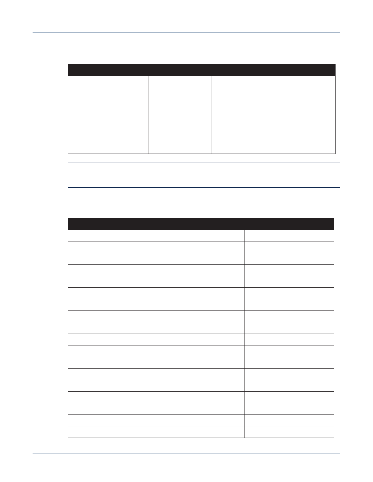
Table 1-3 Switch Specifications (Power Input)
Power Source PSU Models Ratings
Power Input (AC Power) PWR-500AC
PWR-511-AC
PWR-745AC
PWR-747AC
PWR-1011-AC
PWR-1511-AC
Power Input (DC Power) PWR-500-DC
PWR-511-DC
PWR-1011-DC
PWR-1511-DC
PWR-1900-DC
100 - 240 VAC, 6.5 to 3.0 A, 50/60 Hz
100 - 240 VAC, < 7.1 A, 50/60 Hz
100 - 240 VAC, 10.0 to 5.0 A, 50/60 Hz
100 - 240 VAC, 10.0 to 5.0 A, 50/60 Hz
100 - 120 / 200 - 240 VAC, 12/6A50/60 Hz
200 - 240 VAC, 9.6 A, 50/60 Hz
-48 to -60 VDC, 15 A
-48 to -60 VDC, 13 A
-40 to -60 VDC, 30 A
-48 to -60 VDC, 39.5 A
-48 to -60 VDC, 52 A
Note All PSU models are not supported by all switches. Some switches described in this guide could use
power supplies that may no longer be available. Contact your local Arista representative for more
information.
Table 1-4 Switch Specifications (Power Draw)
Switch Power Draw (Typical / Maximum) Supported Power Supply
DCS-7280SE-64 263 W / 381 W PWR-500AC, PWR-500-DC
DCS-7280SE-68 313 W / 405 W PWR-500AC, PWR-500-DC
DCS-7280SE-72 262 W / 399 W PWR-500AC, PWR-500-DC
DCS-7280QR-C36 324 W / 499 W PWR-745AC, PWR-1900-DC
DCS-7280TR-48C6 290 W / 405 W PWR-500AC, PWR-500-DC
DCS-7280SR2A-48YC6 450 W / 685 W PWR-747AC, PWR-1900-DC
DCS-7280TRA-48C6 290 W / 405 W PWR-500AC, PWR-500-DC
DCS-7280QRA-C36S 419 W / 570 W PWR-747AC, PWR-1900-DC
DCS-7280SRAM-48C6 355 W / 400 W PWR-500AC, PWR-500-DC
DCS-7280SR-48C6 263 W / 381 W PWR-500AC, PWR-500-DC
DCS-7280SR2-48YC6 425 W / 647 W PWR-747AC, PWR-1900-DC
DCS-7280SRA-48C6 314 W / 410 W PWR-500AC, PWR-500-DC
DCS-7280SR2K-48C6 215 W / 370 W PWR-747AC, PWR-1900-DC
DCS-7280SRM-40CX2 183 W / 283 W PWR-500AC, PWR-500-DC
DCS-7280CR3-32D4 535 W / 851 W PWR-1011-AC, PWR-1011-DC
DCS-7280CR3-32P4 535 W / 851 W PWR-1011-AC, PWR-1011-DC
DCS-7280DR3-24 560 W / 1110 W PWR-1511-AC, PWR-1511-DC
DCS-7280PR3-24 650 W / 1100 W PWR-1511-AC, PWR-1511-DC
4 Quick Start Guide: 7280 Series 1 RU-Gen 3 Data Center Switches
Page 9
Chapter 1: Overview Specifications
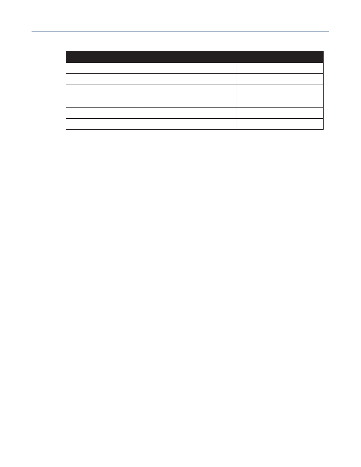
Table 1-4 Switch Specifications (Power Draw) (Continued)
Switch Power Draw (Typical / Maximum) Supported Power Supply
DCS-7280SR3-48YC8 155 W / 325 W PWR-511-AC, PWR-511-DC
DCS-7280SR3K-48YC8 155 W / 325 W PWR-511-AC, PWR-511-DC
DCS-7280CR3K-32D4 535 W / 851 W PWR-1011-AC, PWR-1011-DC
DCS-7280CR3K-32P4 535 W / 851 W PWR-1011-AC, PWR-1011-DC
DCS-7280DR3K-24 560 W / 1110 W PWR-1511-AC, PWR-1511-DC
DCS-7280PR3K-24 650 W / 1100 W PWR-1511-AC, PWR-1511-DC
Quick Start Guide: 7280 Series 1 RU-Gen 3 Data Center Switches 5
Page 10

Specifications Chapter 1: Overview
6 Quick Start Guide: 7280 Series 1 RU-Gen 3 Data Center Switches
Page 11

Chapter 2
Preparation
2.1 Site Selection
The following criteria should be considered when selecting a site to install the switch:
• Temperature and Ventilation: For proper ventilation, install the switch where there is ample
airflow to the front and back of the switch. The ambient temperature should not go below 0° or
exceed 40°C.
Important! To prevent the switch from overheating, do not operate it in an area where the ambient temperature
exceeds 40°C (104°F).
Pour empêcher l’interrupteur de surchauffe, ne pas utiliser il dans une zone où la température ambiante
est supérieure à 40°C (104°F).
• Airflow Orientation: Determine airflow direction of the four fan modules and two power supply
modules on the rear panel. Fan and power supply module handles indicate airflow direction:
• Blue Handle: Air Inlet module.
• Red Handle: Air Exit module.
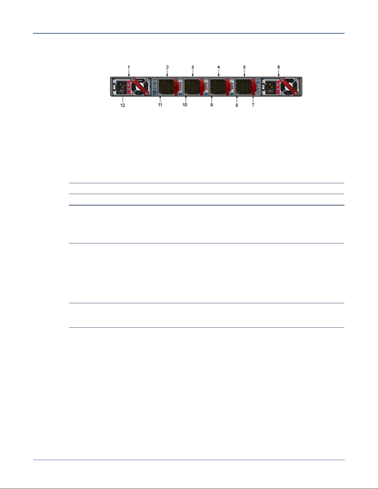
Figure 2-1 on page 8 displays fan and power supply module locations on the rear panel. Their red
handles indicate that they are air exit modules. Verify that each module has the same airflow
direction. Base the switch orientation on the airflow direction of the modules to assure the air inlet
is always oriented toward the cool aisle:
• Air Exit modules: orient the rear panel toward the hot aisle.
• Air Inlet modules: orient the rear panel toward the cool aisle.
If the airflow direction is not compatible with the installation site, contact your sales representative
to obtain modules that circulate air in the opposite direction.
• Rack Space: Install the switch in a 19" rack or cabinet. The switch height is 1 RU. The accessory
kit provides mounting brackets for two-post and four-post racks.
When mounting the switch in a partially filled rack, load the rack from bottom to top, with the
heaviest equipment at the bottom. Load the switch at the bottom if it is the only item in the rack.
• Power Requirements: Power requirements vary by switch and power supply model. Refer to
Table 1-3 on page 4 and Table 1-4 on page 4 for information regarding your specific system.
Two circuits provide redundancy protection. Section 4.1 describes power cable requirements.
Quick Start Guide: 7280 Series 1 RU-Gen 3 Data Center Switches 7
Page 12
Tools and Parts Required for Installation Chapter 2: Preparation
Figure 2-1: Airflow Direction Labels
1 Power supply module
1 label
2 Fan module 1 6 Power supply module 2
3 Fan module 2 7 Fan module handle 11 Fan module 1 status LED
4 Fan module 3 8 Fan module 4 status LED 12 PSU 1 status LED
5 Fan module 4 9 Fan module 3 status LED
10 Fan module 2 status LED
label
Note Handle or label color indicates airflow direction.
Important! The power input plug-socket combination must be accessible at all times; it provides the primary
method of disconnecting power from the system.
La combinaison de la puissance-prise d’entrée doit être accessible en tout temps ; Il fournit le principal
moyen de coupure d’alimentation du système.
• Other Requirements: Select a site where liquids or objects cannot fall onto the equipment and
foreign objects are not drawn into the ventilation holes. Verify these guidelines are met:
• Clearance areas to the front and rear panels allow for unrestricted cabling.
• All front and rear panel indicators can be easily read.
• Power cords can reach from the power outlet to the connector on the rear panel.
Important! All power connections must be removed to de-energize the unit.
Toutes les connexions d’alimentation doivent être enlevées pour hors tension l’appareil.
2.2 Tools and Parts Required for Installation
Each switch provides an accessory kit that contains parts that are required to install the switch. In
addition to the accessory kit, the following tools and equipment are required to install the switch:
Two-Post Rack
• Screws or rack mounting nuts and bolts.
• Screwdriver
Four-Post Rack (Tool-less)
No additional equipment required.
8 Quick Start Guide: 7280 Series 1 RU-Gen 3 Data Center Switches
Page 13

Chapter 2: Preparation Electrostatic Discharge (ESD) Precautions
Four-Post Rack (Conventional)
• Screws or rack mounting nuts and bolts.
• Screwdriver
Accessory kit does not include screws for attaching the switch to the equipment rack. When installing
the switch into an equipment rack with unthreaded post holes, nuts are also required to secure the
switch to the rack posts.
2.3 Electrostatic Discharge (ESD) Precautions
Observe these guidelines to avoid ESD damage when installing or servicing the switch.
• Assemble or disassemble equipment only in a static-free work area.
• Use a conductive work surface (such as an anti-static mat) to dissipate static charge.
• Wear a conductive wrist strap to dissipate static charge accumulation.
• Minimize handling of assemblies and components.
• Keep replacement parts in their original static-free packaging.
• Remove all plastic, foam, vinyl, paper, and other static-generating materials from the work area.
• Use tools that do not create ESD.
Quick Start Guide: 7280 Series 1 RU-Gen 3 Data Center Switches 9
Page 14

Electrostatic Discharge (ESD) Precautions Chapter 2: Preparation
10 Quick Start Guide: 7280 Series 1 RU-Gen 3 Data Center Switches
Page 15

Chapter 3
Rack Mounting the Switch
Important! The rack mounting procedure is identical for all switches covered by this guide. Illustrations in this
chapter depict the mounting of a DCS-7050QX-32S switch.
Les procédure de montage du bâti est identique pour tous les commutateurs visés par ce guide.
Illustrations dans ce chapitre montrent le montage d’un interrupteur de DCS-7050QX-32S.
• Section 3.1 provides instructions for mounting the switch in a two-post rack.
• Section 3.2 provides instructions for mounting the switch in a four-post rack.
After completing the instructions for your rack type, proceed to Chapter 4.
3.1 Two-Post Rack Mount
To mount the switch onto a two-post rack, assemble the mounting brackets to the chassis, then attach
the brackets to the rack posts. Two-post accessory kits include the following two-post mounting parts:
• 2 three-hole mounting brackets
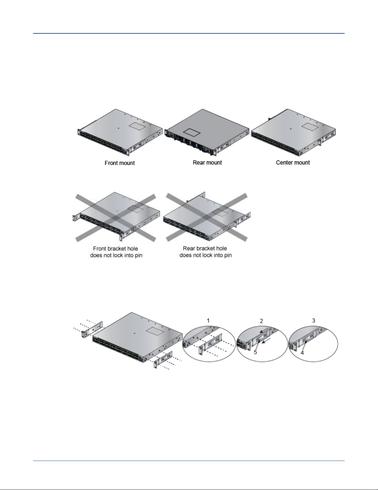
Each chassis side has attachment pins that align with bracket holes. Pin orientation is symmetric and
equidistant, supporting bracket placements where the flange is flush with the front switch panel, flush
with the rear panel, or not flush with either panel. Each bracket hole includes a key-opening for placing
the bracket flush with the chassis and then locking it into place.
Important! Attachment pins must engage all three upper bracket holes.
Goupilles de fixation doivent être bloquer tous les trois trous de la bride supérieure..
Figure 3-1 displays proper bracket mount configuration examples. Figure 3-2 displays improper bracket
mount configuration examples.
Quick Start Guide: 7280 Series 1 RU-Gen 3 Data Center Switches 11
Page 16
Two-Post Rack Mount Chapter 3: Rack Mounting the Switch
3.1.1 Attaching Mounting Brackets to the Chassis
This procedure attaches mounting brackets to the switch chassis (Figure 3-3).
Step 1 Align the mounting brackets with the attachment pins to obtain the desired mounting position.
Step 2 Place the bracket flush on the chassis with attachment pins protruding through key-openings.
Figure 3-1: Bracket Mount Examples for Two-Post Rack Mount
Figure 3-2: Improper Bracket Mount Examples for Two-Post Rack Mount
Step 3 Slide the bracket toward the front flange until the bracket clip locks with an audible click.
Figure 3-3: Attaching the Mounting Brackets to the Switch Chassis
1 Step 1 4 Bracket clip (attached)
2 Step 2 5 Bracket clip (aligned)
3 Step 3
To remove the mounting bracket from the chassis, lift the front edge of the mounting bracket clip with a
flathead screwdriver and slide the bracket away from the front flange (opposite from the installation
direction).
12 Quick Start Guide: 7280 Series 1 RU-Gen 3 Data Center Switches
Page 17
Chapter 3: Rack Mounting the Switch Four-Post Rack Mount
3.1.2 Inserting the Switch into the Rack
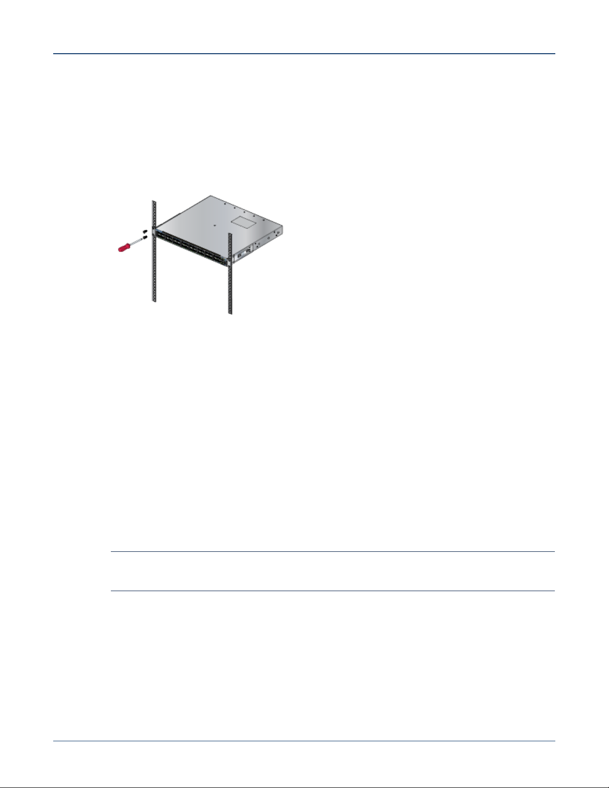
This procedure attaches the switch to the rack (Figure 3-4).
Step 1 Lift the chassis into the rack. Position the flanges against the rack posts.
Step 2 Select mounting screws that fit your equipment rack.
Step 3 Attach the bracket flanges to the rack posts.
Figure 3-4: Inserting the Switch into the Rack
After completing the two-post rack mount, proceed to Chapter 4.
3.2 Four-Post Rack Mount
The switch is mounted onto a four-post rack by assembling two rails onto the rear posts, sliding the
switch onto the rails, then securing the switch to the front posts.
The installation kit provides the following four-post mounting parts:
• 2 six-hole mounting brackets
• 2 rail-rods
• 2 rail-slides
The rail-rods and rail-slides assemble into two identical slide-rails.
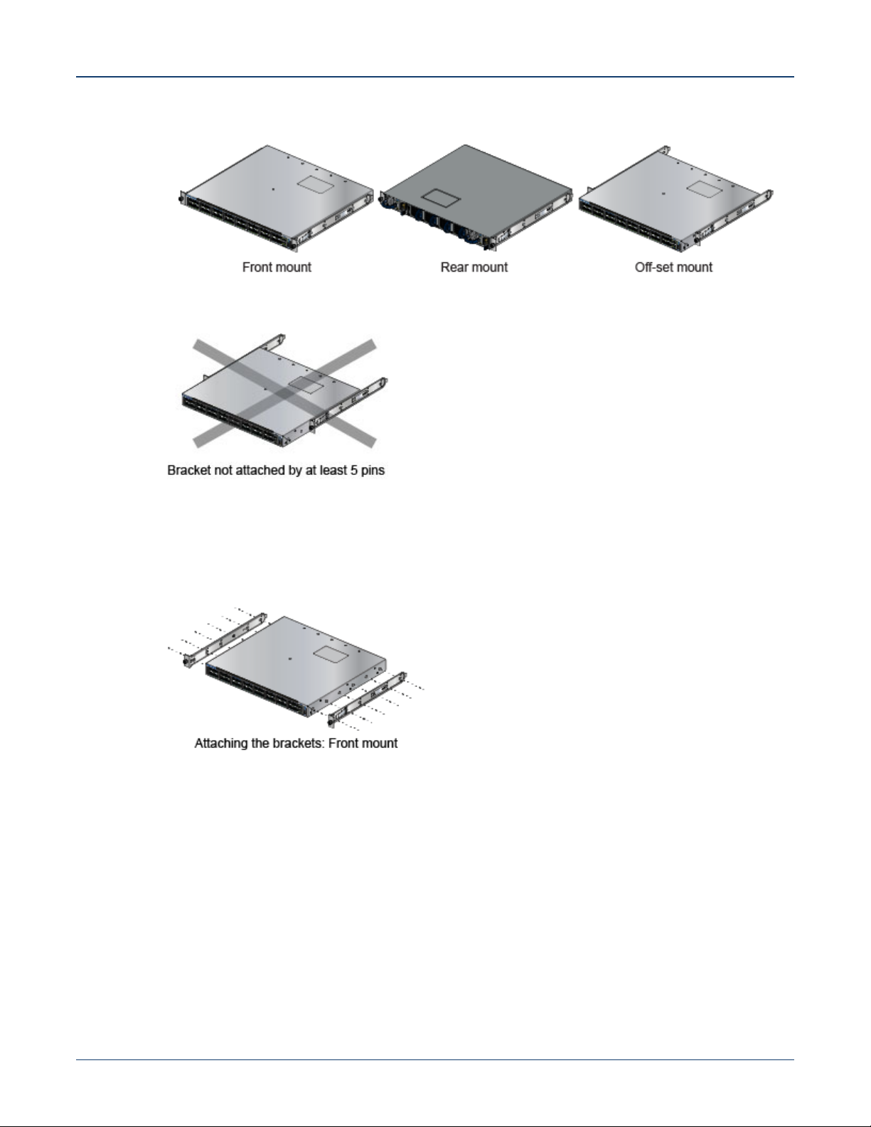
Each chassis side has attachment pins that align with bracket holes. Pin orientation is symmetric and
equidistant, supporting bracket placements where the flange is flush with the front switch panel, flush
with the rear panel, or not flush with either panel. Each bracket hole includes a key-opening for placing
the bracket flush with the chassis and then locking it into place.
Important! Attachment pins must engage at least five of the six bracket holes.
Goupilles de fixation doivent être lock au moins cinq des trous du six support.
Figure 3-5 displays proper bracket mount configuration examples. Figure 3-6 displays an improper
bracket mount configuration example.
Quick Start Guide: 7280 Series 1 RU-Gen 3 Data Center Switches 13
Page 18
Four-Post Rack Mount Chapter 3: Rack Mounting the Switch
Figure 3-5: Bracket Mount Examples for Four-Post Rack Mount
Figure 3-6: Improper Bracket Mount Example for Four-Post Rack Mount
3.2.1 Attaching Mounting Brackets to the Chassis
Figure 3-7 displays the front bracket alignment for mounting the switch into a four-post rack.
Figure 3-7: Attaching the Mounting Brackets to the Switch Chassis
This procedure attaches mounting brackets to the switch chassis as depicted by Figure 3-7.
Step 1 Align the mounting brackets with the attachment pins to obtain the desired mounting position.
Step 2 Place the bracket flush on the chassis with attachment pins protruding through key-openings.
Step 3 Slide the bracket toward the front flange until the bracket clip locks with an audible click.
To remove the mounting bracket from the chassis, lift the front edge of the mounting bracket clip with a
flathead screwdriver and slide the bracket away from the front flange (opposite from the installation
direction).
14 Quick Start Guide: 7280 Series 1 RU-Gen 3 Data Center Switches
Page 19
Chapter 3: Rack Mounting the Switch Four-Post Rack Mount
3.2.2 Assembling the Rails onto the Equipment Rack
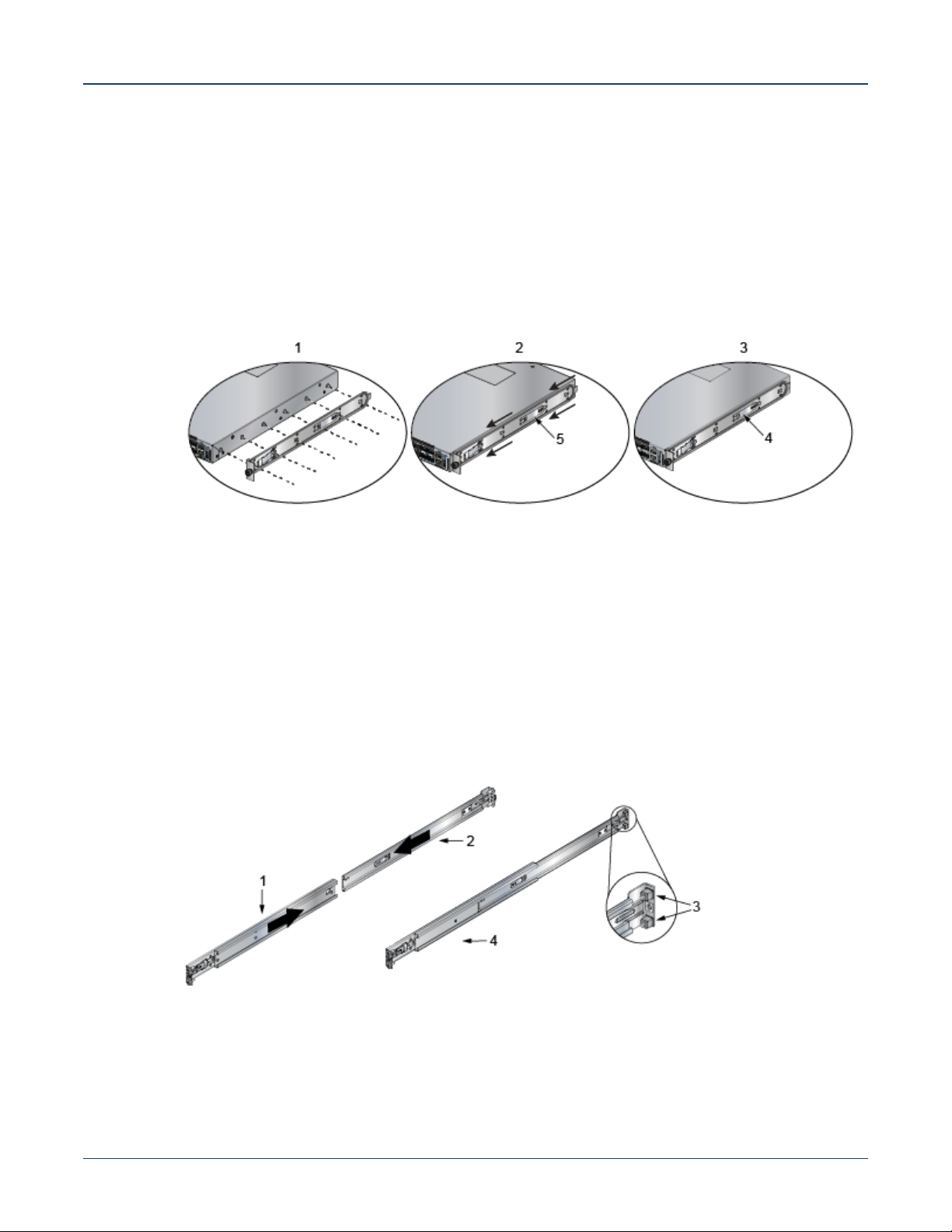
Rail-rods and rail-slides assemble into two identical rails. Each rail connects a front post to a rear post.
When the rails are installed, the switch slides on the rails into the rack. Each bracket includes a screw
that attaches the switch to the rail.
Each end of an assembled rail contains two rack plugs (Figure 3-8). The rails are installed into a rack
by inserting the plugs into rack slots. When installing rails into posts with threaded or rounded holes,
remove all plugs located on both sides of the assembled rails, then install the rails with bolts that fit the
rack.
Figure 3-8: Attaching the Mounting Brackets to the Switch Chassis
1 Step 1 4 Bracket clip (attached)
2 Step 2 5 Bracket clip (aligned)
3 Step 3
This procedure attaches the rails to a four post rack:
Step 1 Slide a rail-rod into a rail-slide (Figure 3-9) until the rail clip makes an audible click.
The rail clip prevents the extension of the rail beyond the maximum supported distance
between the front and rear rack posts.
Figure 3-9: Assembling the Rails
1 Rail-slide 4 Rail (assembled)
2 Rail-rod
3 Rack plugs
Quick Start Guide: 7280 Series 1 RU-Gen 3 Data Center Switches 15
Page 20
Four-Post Rack Mount Chapter 3: Rack Mounting the Switch
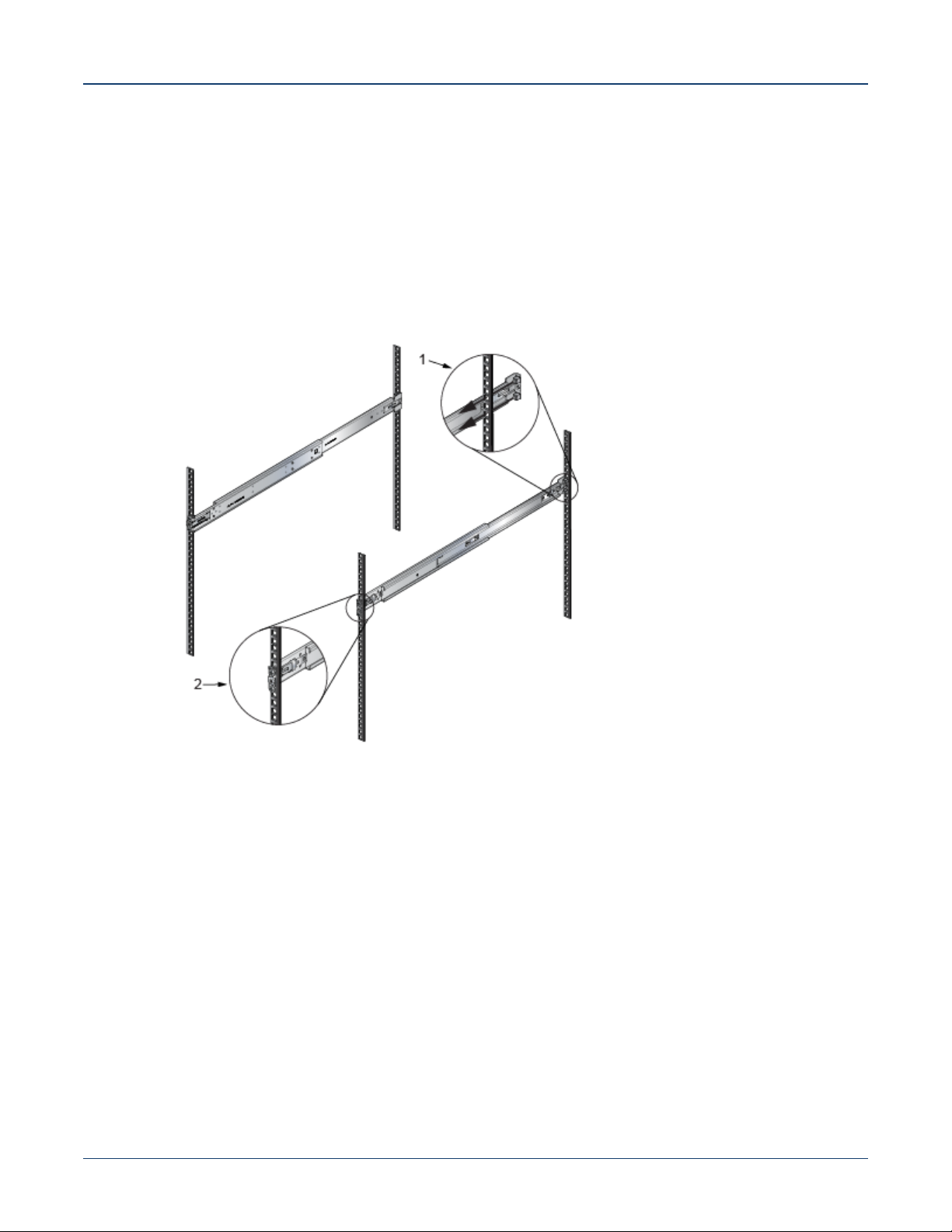
Step 2 Attach rail to the right rear rack post by inserting rod-end rack plugs into post slots
(Figure 3-10, Inset A). The slide assembly must be inside the right posts, relative to the left
rack posts.
If the rack plugs were previously removed, use bolts to attach the rail to the rack.
Step 3 Attach the slide end of the rail to the front post by extending the rail end past the post, then
contracting the rail while guiding the rack plugs into the post (Figure 3-10, Inset B).
Step 4 Repeat step 1 through step 3 for the left posts. Ensure the rails are on the same horizontal
level.
Figure 3-10: Attaching the Rails
1 Inset A
2 Inset B
16 Quick Start Guide: 7280 Series 1 RU-Gen 3 Data Center Switches
Page 21
Chapter 3: Rack Mounting the Switch Four-Post Rack Mount
3.2.3 Attaching the Switch to the Rack
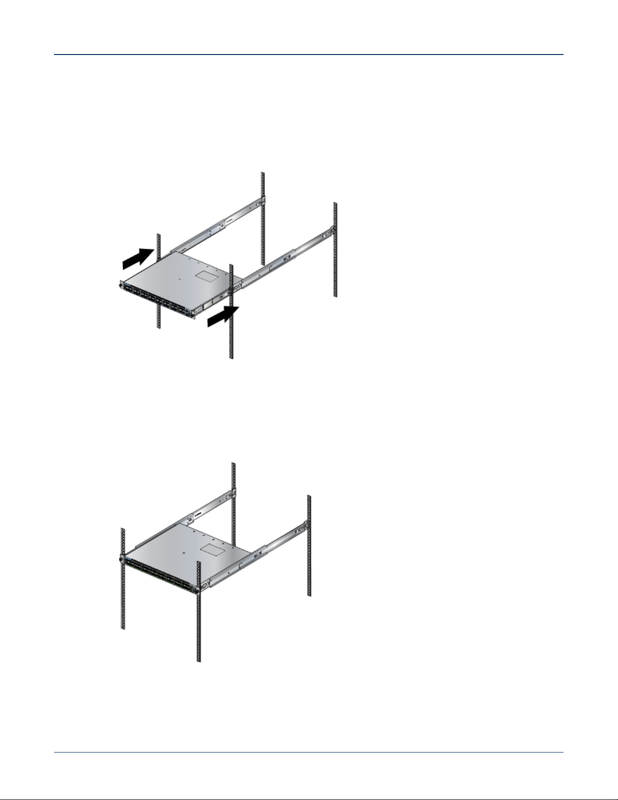
After the rails are installed, the switch slides on the rails into the rack. Each bracket includes a thumb
screw that attaches the switch to the rail.
Step 1 Lift the switch into the rack and insert the mounting brackets into the slide rails.
Figure 3-11: Inserting the Switch onto the Rails
Step 2 Slide the switch on the rails, toward the rear posts, until the mounting bracket flanges are flush
with the rail flanges attached to the rack posts.
Step 3 Attach the bracket flanges to the rack post using the quick-release thumb screws supplied with
the brackets (Figure 3-12).
Figure 3-12: Attaching the Switch to the Rack Posts
After completing the four-post rack mount, proceed to Chapter 4.
Quick Start Guide: 7280 Series 1 RU-Gen 3 Data Center Switches 17
Page 22

Four-Post Rack Mount Chapter 3: Rack Mounting the Switch
18 Quick Start Guide: 7280 Series 1 RU-Gen 3 Data Center Switches
Page 23
Chapter 4
Cabling the Switch
4.1 Grounding the Switch
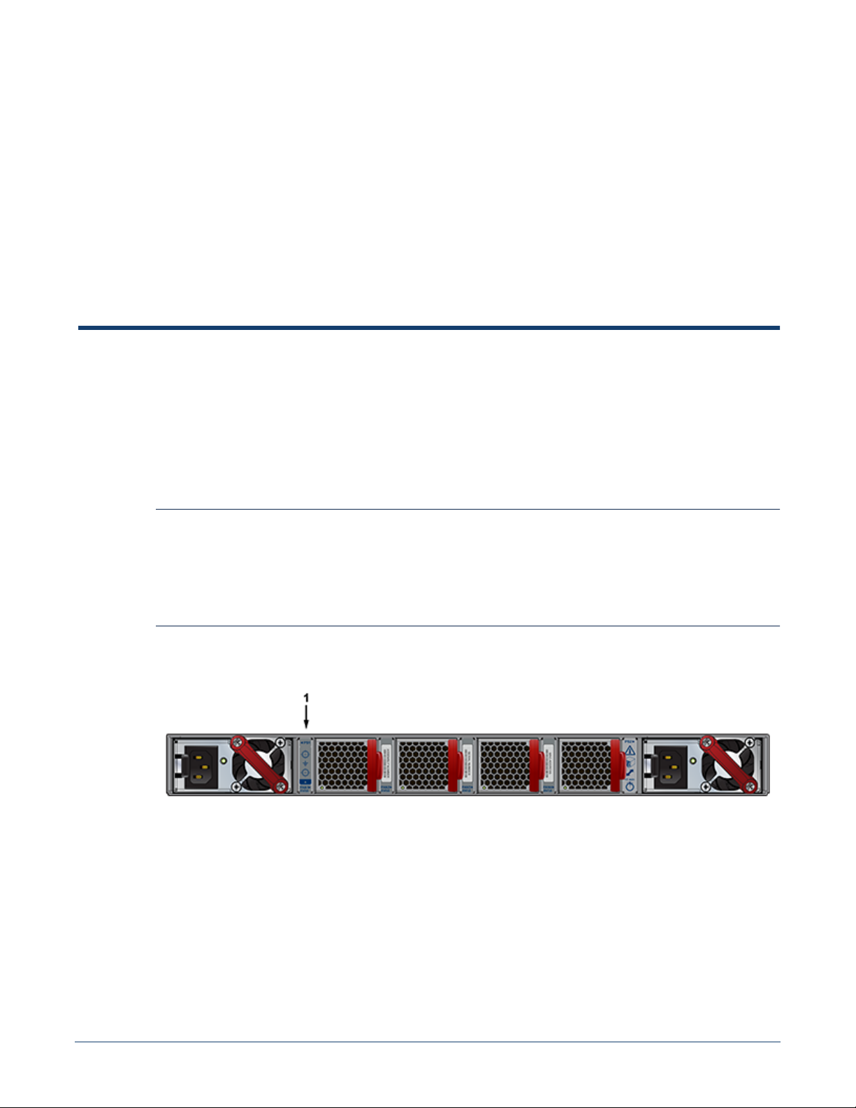
After mounting the switch into the rack, connect the switch to the data center ground. Figure 4-1
displays the location of the grounding pads located on the bottom corners of the rear panel for the
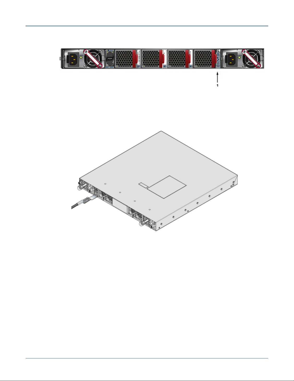
models that have no management ports on the rear panel. Figure 4-2 displays the location of the
grounding pads on the rear panel for models that have management ports on the rear panel. There are
threaded holes under the sticker on the right (next to PS2) that warns about “1 min”. Figure 4-3 displays
the location of the grounding assembly on the rear panel for DCS-7280CR3-32P4.
Important! Grounding wires and grounding lugs (M4 x 0.7) are not supplied. Wire size should meet local and
national installation requirements. Commercially available 6 AWG wire is recommended for
installations in the U.S
À la terre et de mise à la terre fils cosses (M4 x 0.7) ne sont pas fournis. Calibre des fils doit satisfaire
des exigences de l’installation locale et nationale. Disponible dans le commerce 6 fils AWG est
recommandé pour les installations aux États-Unis.
Figure 4-1: Earth Grounding Pad Sockets for Models without Management Ports on the Rear Panel
1 Earth grounding pads
Quick Start Guide: 7280 Series 1 RU-Gen 3 Data Center Switches 19
Page 24
Grounding Adapter Assembly (DCS-7280CR3-32P4) Chapter 4: Cabling the Switch
Figure 4-2: Earth Grounding Pad Sockets for Models with Management Ports on the Rear Panel
1 Earth grounding pads
Figure 4-3: Earth Grounding
Adapter for DCS-7280CR3-32P4
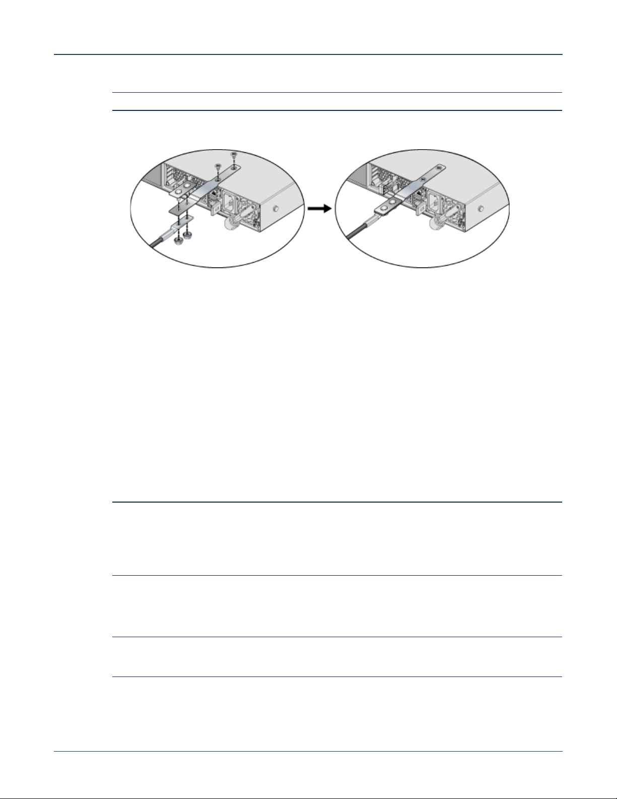
4.2 Grounding Adapter Assembly (DCS-7280CR3-32P4)
Use the following steps to assemble and attach a grounding assembly to the chassis before mounting
it into the rack. Figure 4-4 shows the exploded and assembled views.
20 Quick Start Guide: 7280 Series 1 RU-Gen 3 Data Center Switches
Page 25
Chapter 4: Cabling the Switch Connecting Power Cables
Figure 4-4: Earth Grounding Adapter Assembly for DCS-7280CR3-32P4
Note The chassis is shown upside down in the following figure.
Step 1 Identify all the components to be assembled:
• 1x Grounding adapter
• 1x Grounding bracket
• 2x Flat-head screws (Phillips,M4 x 5.00 long, stainless steel)
• 2x Hex nuts (#10-32, Serrated Flange, stainless steel)
• 1x Grounding lug (Copper, 2-hole, 6 AWG, straight barrel)
Step 2 Insert the grounding adapter through the holes in the grounding bracket.
Step 3 Insert the ground lug on to the grounding adapter studs and fasten using the hex nuts to form
the grounding assembly.
Step 4 With the chassis on its top on a flat surface, attach the grounding assembly to the chassis
using the flat head screws.
Step 5 Turn the chassis over before mounting it into a rack and connecting cables.
4.3 Connecting Power Cables
Important! Installation of this equipment must comply with local and national electrical codes. If necessary, consult
with the appropriate regulatory agencies and inspection authorities to ensure compliance.
Installation de cet équipement doit être conformes aux codes électriques locaux et nationaux. Si
nécessaire, consulter les organismes de réglementation appropriés et des autorités de contrôle pour
assurer la conformité.
The switch operates with two installed power supplies. At least one power supply must connect to a
power source. Two circuits provide redundancy protection. Appendix D displays the location of the
power supplies on the rear panel of the switch.
Important! Read all installation instructions before connecting the system to the power source.
Lire toutes les instructions d’installation avant de brancher le système à la source d’alimentation.
• Non-Redundant Configuration: Connect power to either of the two power supplies.
• Redundant Power Supply Configuration: Connect power to both power supplies.
Quick Start Guide: 7280 Series 1 RU-Gen 3 Data Center Switches 21
Page 26
Connecting Power Cables Chapter 4: Cabling the Switch
• Power down the Switch: Remove all power cords and wires from the power supplies.
Important! This equipment must be grounded. Never defeat the ground conductor.
Cet équipement doit être mis à la terre. Ne jamais modifier le conducteur de terre.
Important! This unit requires overcurrent protection.
Cet appareil requiert une protection contre les surintensités.
4.3.1 AC Power Supplies
The following AC power supplies are supported.
• PWR-500AC • PWR-745AC • PWR-1011-AC
• PWR-511-AC • PWR-747AC • PWR-1511-AC
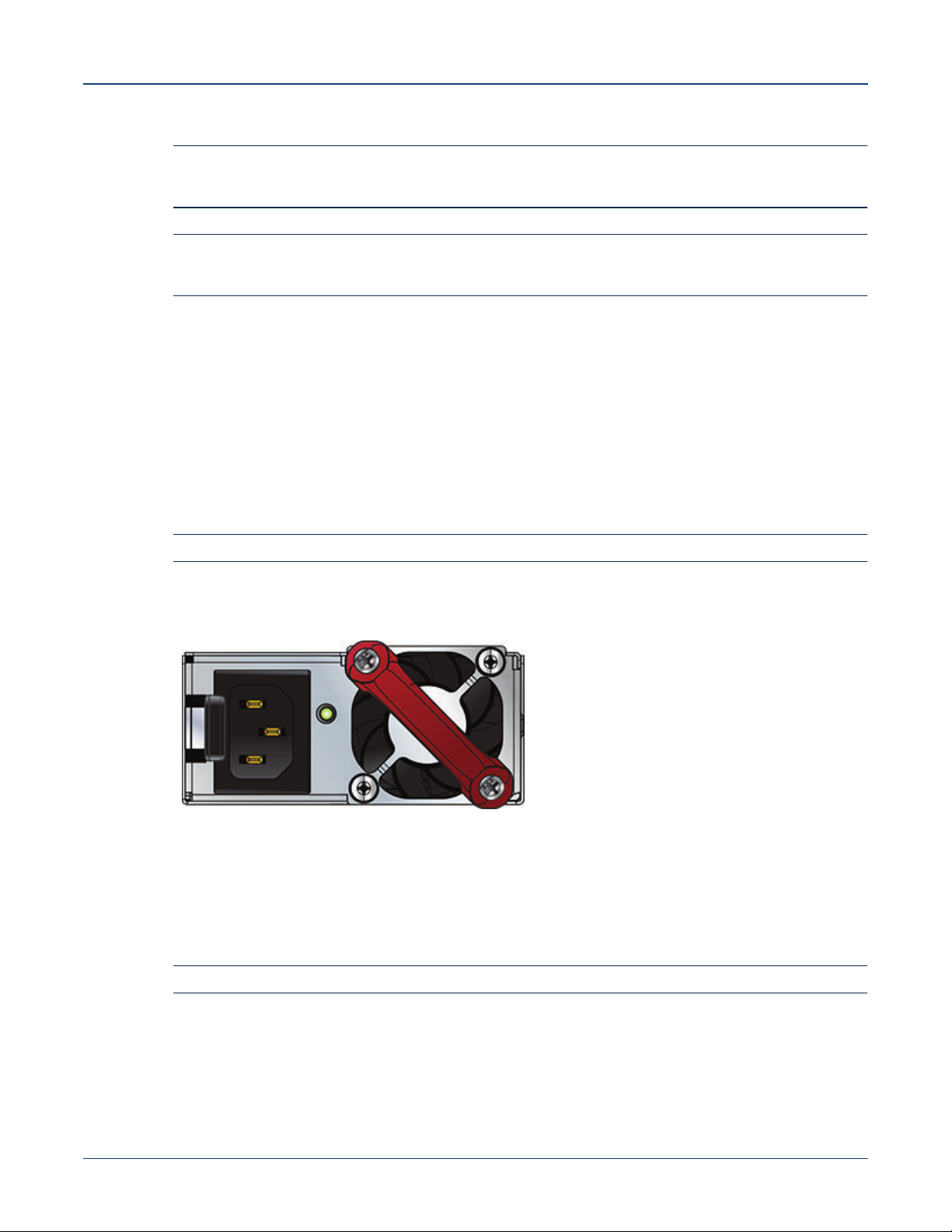
Figure 4-5 displays an AC power supply, including the power socket on the left side of the module. The
AC power supply connects to a circuit that provides the required power, as specified by Table 1-4 on
page 4.
Note Several PSUs support both forward and reverse airflow directions.
Figure 4-5: AC Power Supply Example
The power supplies require power cables that comply with IEC-320 and have a C14 connector. The
accessory kit provides two IEC-320 C13 to C14 power cables.
4.3.2 DC Power Supplies
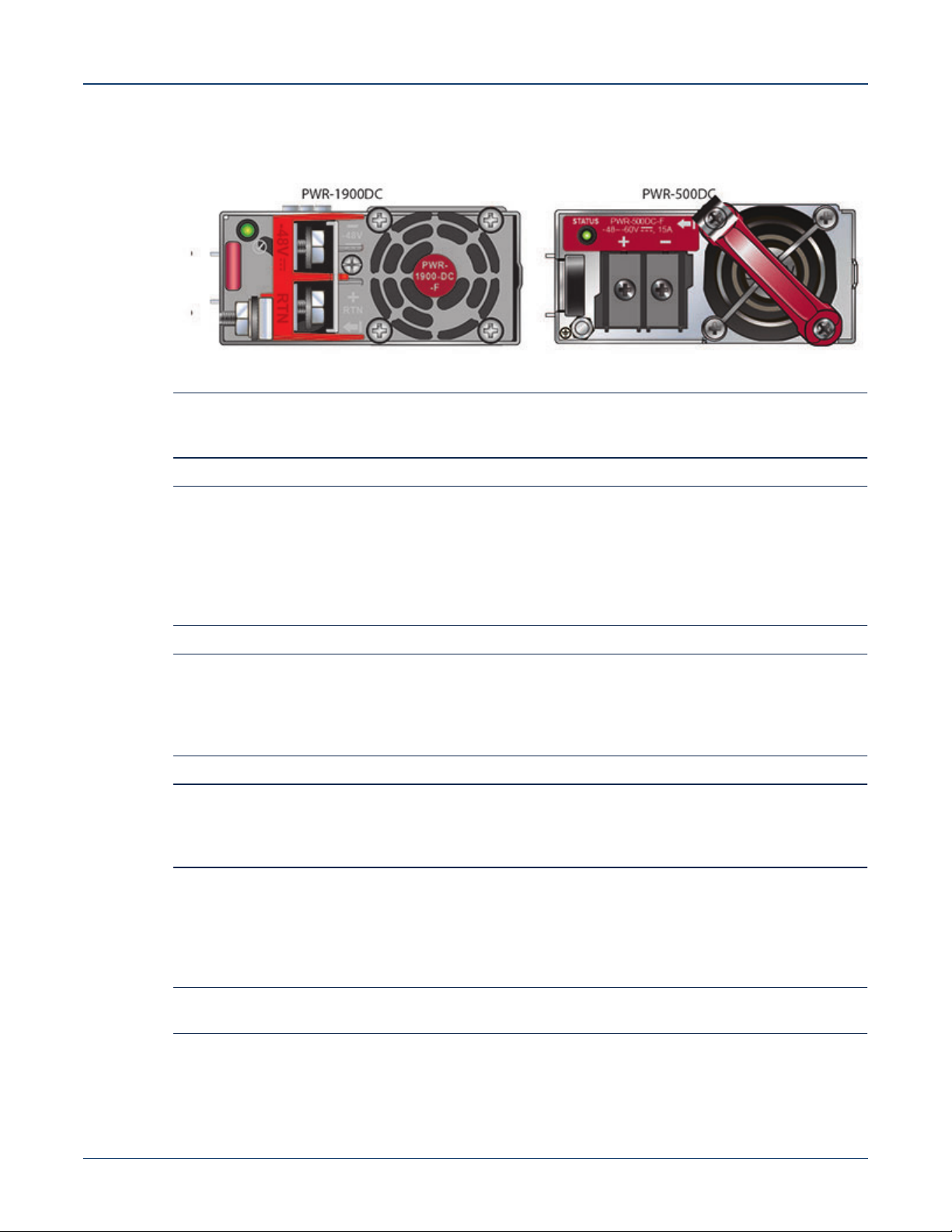
The following DC power supplies are supported.
Note Several PSUs support both forward and reverse airflow directions.
• PWR-500-DC • PWR-1900-DC • PWR-1511-DC
• PWR-511-DC • PWR-1011-DC
22 Quick Start Guide: 7280 Series 1 RU-Gen 3 Data Center Switches
Page 27
Chapter 4: Cabling the Switch Connecting Power Cables
Figure 4-6 displays examples of DC power supplies.
Figure 4-6: DC Power Supply Examples
Important! A disconnect device must be provided as part of the installation .
Un dispositif de sectionnement doit être fourni dans le cadre de l'installation.
Important! Ensure power is removed from DC circuits before performing any installation actions. Locate the
disconnect device, circuit breakers or fuses on DC power lines servicing the circuits.
Turn off the power line circuits or remove the fuses.
Pouvoir assurer qu'il est retiré de circuits DC avant d'effectuer des actions d'installation . Localiser les
disjoncteurs ou des fusibles sur les lignes de courant continu desservant les circuits.
Coupez les circuits de lignes d'alimentation ou retirer les fusibles.
Important! Wire size must comply with local and national requirements and electrical codes.
Use only copper wire.
Le calibre du fil doit être conforme aux exigences locales et nationales et les codes électriques.
Utiliser du fil de cuivre.
Important! Apply ground connection to the switch first during installation and remove last when removing power.
Appliquer connexion à la terre à l'interrupteur premier lors de l'installation et de supprimer la dernière
alimentation lors du débranchement.
4.3.2.1 Wire and Lug Preparation
Before performing any installation actions, ensure power is removed from DC circuits by turning off the
power line servicing the circuits. Prepare the stranded wiring before you begin a DC power installation.
Note Stranded copper wiring is required and should meet local and national installation requirements. Wires
and grounding lugs are not supplied.
Step 1 Attach an ESD grounding strap.
Quick Start Guide: 7280 Series 1 RU-Gen 3 Data Center Switches 23
Page 28
Connecting Power Cables Chapter 4: Cabling the Switch
Step 2 Prepare the stranded copper wiring for the power supply to be used. Table 4-1 provides wiring,
lug, and tightening torque information for the power supplies covered in this guide.
Table 4-1 Wiring, Lug, and Tightening Torques for DC PSUs
PSU
Wire Size
(AWG) (mm2) N•m in.•lbs.
PWR-500-DC 14 or larger 2.0 or larger ring or
PWR-511-DC 12 - 14 4.0 - 2.5 1.0 9
PWR-1900-DC 4 - 6 21.2 - 13.3 2.7 24
PWR-1011-DC 6 - 8 16.0 - 10.0 2.7 24
PWR-1511-DC 4 - 6 25.0 - 16.0 2.7 24
1. Unless otherwise noted, wire size applies to -48V, Battery return, and Protective earth wires.
2. Unless otherwise noted, twin #10 studs spaced for dual-hole lug with 5/8" hole spacing.
(1)
Lug Type
spade/fork
(2)
Tightening Torque
1.0 9
Step 3 Strip the wires to the appropriate length for the lugs to be used.
Step 4 Use agency-approved compression (pressure) lugs for wiring terminations.
Step 5 Slip on heat-shrink tubing on the wire ends before assembling the lugs on to the wire.
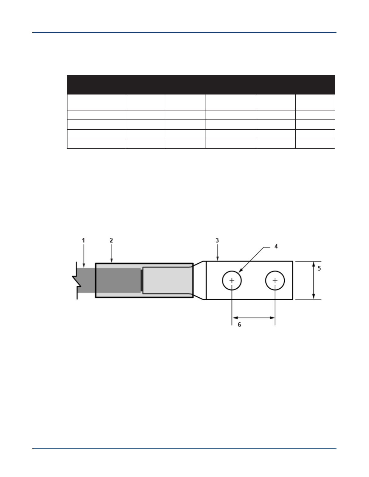
Step 6 Crimp the lugs with the proper tool, and ensure that the tubing extends over the barrel of the
lugs and the insulation on the wires (Figure 4-7).
Figure 4-7: Lug preparation
1 Insulated wire 3 Lug 5 1/2”
2 Heat-shrink tubing 4 1/4” 6 5/8”
Step 7 Shrink the tubing with a heat gun.
4.3.2.2 Connecting a DC Power Supply to Power Source
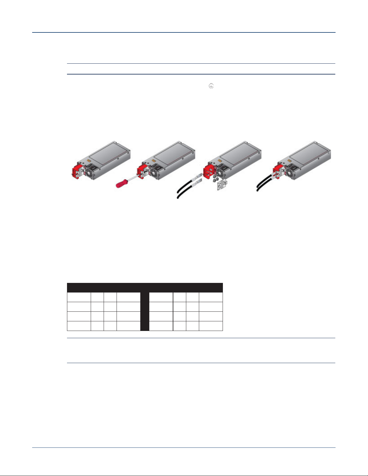
Figure 4-8 displays an example of connecting a PSU. To connect a DC power supply to a power source,
perform the following:
Step 1 Prepare the stranded wiring (Wire and Lug Preparation).
Step 2 Attach the appropriate lugs to the source DC wires.
24 Quick Start Guide: 7280 Series 1 RU-Gen 3 Data Center Switches
Page 29
Chapter 4: Cabling the Switch Connecting Serial and Management Cables
Step 3 Connect the DC-input wires to the appropriate terminals using the specified torque (Table 4-1)
in the following order.
Note Remove terminal covers as needed.
a. Ground wire to the Protective Earth (PE ) terminal.
b. Negative source DC cable to the negative (- / -48V) terminal.
c. Positive (+) source DC cable to the positive (+ / Rtn) terminal.
Step 4 Replace the terminal covers as required.
Figure 4-8: DC PSU connection example
4.4 Connecting Serial and Management Cables
The accessory kit includes the following cables:
• RJ-45 to DB-9 serial adapter cable.
• RJ-45 Ethernet cable.
Table 4-2 lists the pin connections of the RJ-45 to DB-9 adapter cable.
Table 4-2 RJ-45 to DB-9 Connections
RJ-45 DB-9 RJ-45 DB-9
RTS 1 8 CTS
DTR 2 6 DSR
TXD 3 2 RXD
GND 4 5 GND
Note RJ-45 to DB-9 connections: For models with a console management port on the rear panel, RJ-45 pin
1 (RTS) is connected to RJ-45 pin 8 (CTS); RJ-45 pin 2 (DTR) and RJ-45 pin 7 (DSR) are not
electrically connected to any signal.
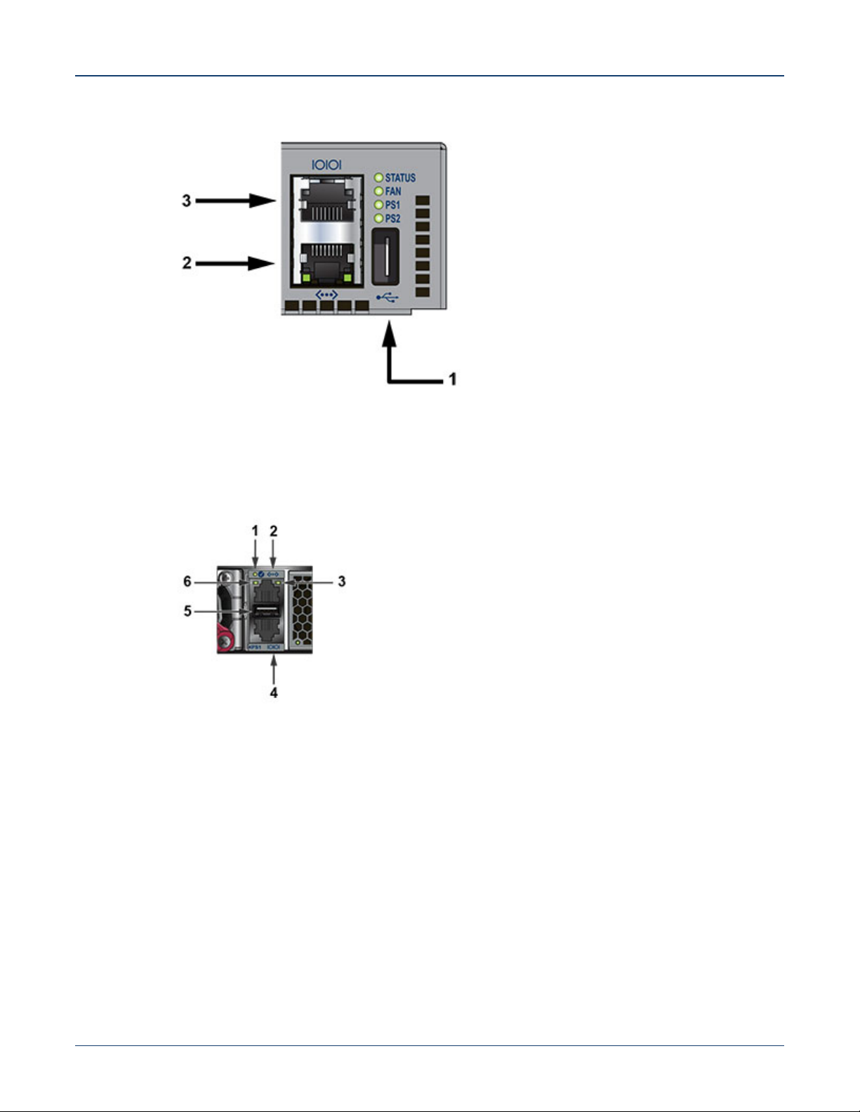
For most models, the front panel contains the console, management, and USB ports. Figure 4-9
displays the ports on the front panel of the DCS-7050QX-32S switch. Figure 4-10 displays the ports on
rear panel of the DCS-7280SR-48C6 switch. Appendix C and Appendix D display the front and rear
panels of all switches covered by this guide.
GND 5 5 GND
RXD 6 3 TXD
DSR 7 4 DTR
CTS 8 7 RTS
Quick Start Guide: 7280 Series 1 RU-Gen 3 Data Center Switches 25
Page 30
Connecting Serial and Management Cables Chapter 4: Cabling the Switch
Figure 4-9: Front Panel Ports
1 USB port 3 Console serial port
2 Ethernet management port
Figure 4-10: Rear Panel Ports
1 System status LED 3 Activity status LED 5 USB port
2 Ethernet management port 4 Console serial port 6 Link status LED
Connect the front or rear panel ports as follows:
• Console (Serial) Port: Connect to a PC with the RJ-45 to DB-9 serial adapter cable.
The switch uses the following default settings:
• 9600 baud
• No flow control
• 1 stop bit
• No parity bits
• 8 data bits
• Ethernet Management Port: Connect to 10/100/1000 management network with RJ-45 Ethernet
cable.
26 Quick Start Guide: 7280 Series 1 RU-Gen 3 Data Center Switches
Page 31

Chapter 4: Cabling the Switch Connecting Serial and Management Cables
• USB Port: The USB port may be used for software or configuration updates.
Caution Excessive bending can damage interface cables, especially optical cables.
Flexion excessive peut endommager les câbles d’interface, notamment des câbles optiques.
Quick Start Guide: 7280 Series 1 RU-Gen 3 Data Center Switches 27
Page 32

Connecting Serial and Management Cables Chapter 4: Cabling the Switch
28 Quick Start Guide: 7280 Series 1 RU-Gen 3 Data Center Switches
Page 33

Configuring the Switch
Arista switches ship from the factory in Zero Touch Provisioning (ZTP) mode. ZTP configures the switch
without user intervention by downloading a startup configuration file or a boot script from a location
specified by a DHCP server. To manually configure a switch, ZTP is bypassed. The initial configuration
provides one username (admin) accessible only through the console port because it has no password.
When bypassing ZTP, initial switch access requires logging in as admin, with no password, through the
console port. Then you can configure an admin password and other password protected usernames.
This manual configuration procedure cancels ZTP mode, logs into the switch, assigns a password to
admin, assigns an IP address to the management port, and defines a default route to a network
gateway.
Chapter 5
Step 1 Provide power to the switch (Section 4.1).
Step 2 Connect the console port to a PC (Section 4.4).
As the switch boots without a startup-config file, it displays the following through the console:
The device is in Zero Touch Provisioning mode and is attempting to
download the startup-config from a remote system. The device will not
be fully functional until either a valid startup-config is downloaded
from a remote system or Zero Touch Provisioning is cancelled. To cancel
Zero Touch Provisioning, login as admin and type 'zerotouch cancel'
at the CLI.
localhost login:
Step 3 Log into the switch by typing admin at the login prompt.
localhost login:admin
Step 4 Cancel ZTP mode by typing zerotouch cancel. IMPORTANT: This step initiates a switch
reboot.
localhost>zerotouch cancel
Step 5 After the switch boots, log into the switch again by typing admin at the login prompt.
Arista EOS
localhost login:admin
Last login: Fri Mar 15 13:17:13 on console
Step 6 Enter global configuration mode.
localhost>enable
localhost#config
Quick Start Guide: 7280 Series 1 RU-Gen 3 Data Center Switches 29
Page 34

Chapter 5: Configuring the Switch
Step 7 Assign a password to the admin username with the username secret command.
localhost(config)#username admin secret pxq123
Step 8 Configure a default route to the network gateway.
localhost(config)#ip route 0.0.0.0/0 192.0.2.1
Step 9 Assign an IP address (192.0.2.8/24 in this example) to an Ethernet management port.
localhost(config)#interface management 1
localhost(config-if-Ma1/1)#ip address 192.0.2.8/24
Step 10 Save the configuration by typing write memory or copy running-config startup-config.
localhost#copy running-config startup-config
When the management port IP address is configured, use this command to access the switch from a
host, using the address configured in step 9:
Refer to the Arista Networks User Manual for complete switch configuration information.
30 Quick Start Guide: 7280 Series 1 RU-Gen 3 Data Center Switches
Page 35
Status Indicators
A.1 Front Indicators
A.1.1 Switch Indicators
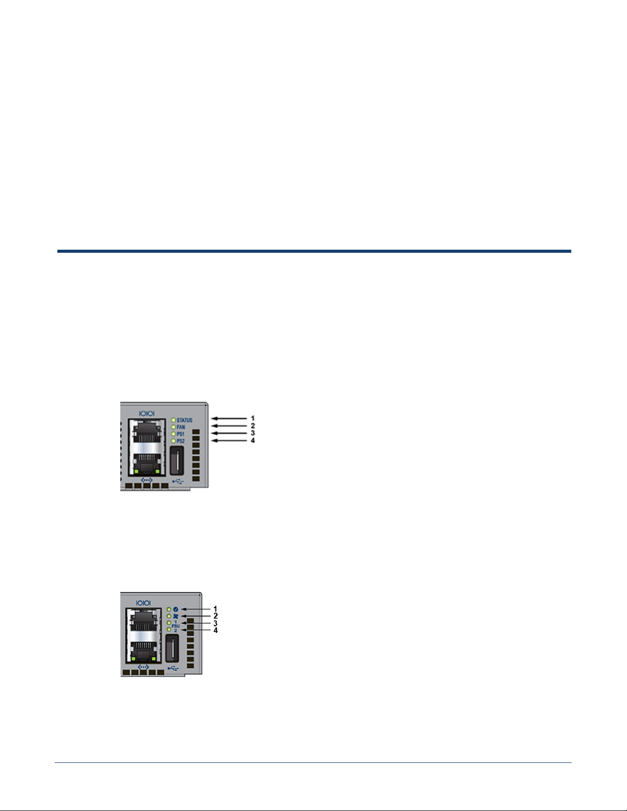
Front panel LEDs are located on the right side of the chassis and display system, fan, and power supply
status. The front panel LEDs are labeled either as in Figure A-1 or as in Figure A-2. Check your device
for the specific method utilized.
Figure A-1: System Status Indicators
Appendix A
1 System status LED 3 Power supply 1 status LED
2 Fan status LED 4 Power supply 2 status LED
Figure A-2: System Status Indicators
1 System status LED 3 Power supply 1 status LED
2 Fan status LED 4 Power supply 2 status LED
Quick Start Guide: 7280 Series 1 RU-Gen 3 Data Center Switches 31
Page 36
Front Indicators Appendix A: Status Indicators
Table A-1 Switch Indicators LED States (Front)
LED Name LED State Device Status
System Status LED Blinking Green System is powering up.
Fan Status LED Green All fan and power modules are operating normally.
PSU [1:2] Status LED Green PSU is functioning and fully operational. AC is present, Aux
A.1.2 Port Indicators
Green Normal operations. Due to power supply and fan redundancy,
this LED will remain green if a single fan or power supply is
missing or in a failed state.
Blue The locater function is active.
Amber Two or more fans (any combination of fan modules or PSU
fans) are disconnected or malfunctioning. The switch will
automatically execute a “graceful shutdown” shortly.
Amber Single fan module is removed or malfunctioning. It is also
amber when a PSU is completely removed or has a stuck
fan rotor.
Red Two or more fans (any combination of fan modules or PSU
fans) are disconnected or malfunctioning. The switch will
automatically execute a “graceful shutdown” shortly.
output is ON, and Main output is ON.
Off PSU has been removed or is not operating properly due to AC
cord being unplugged, its fan rotor being stuck, or an internal
fault.
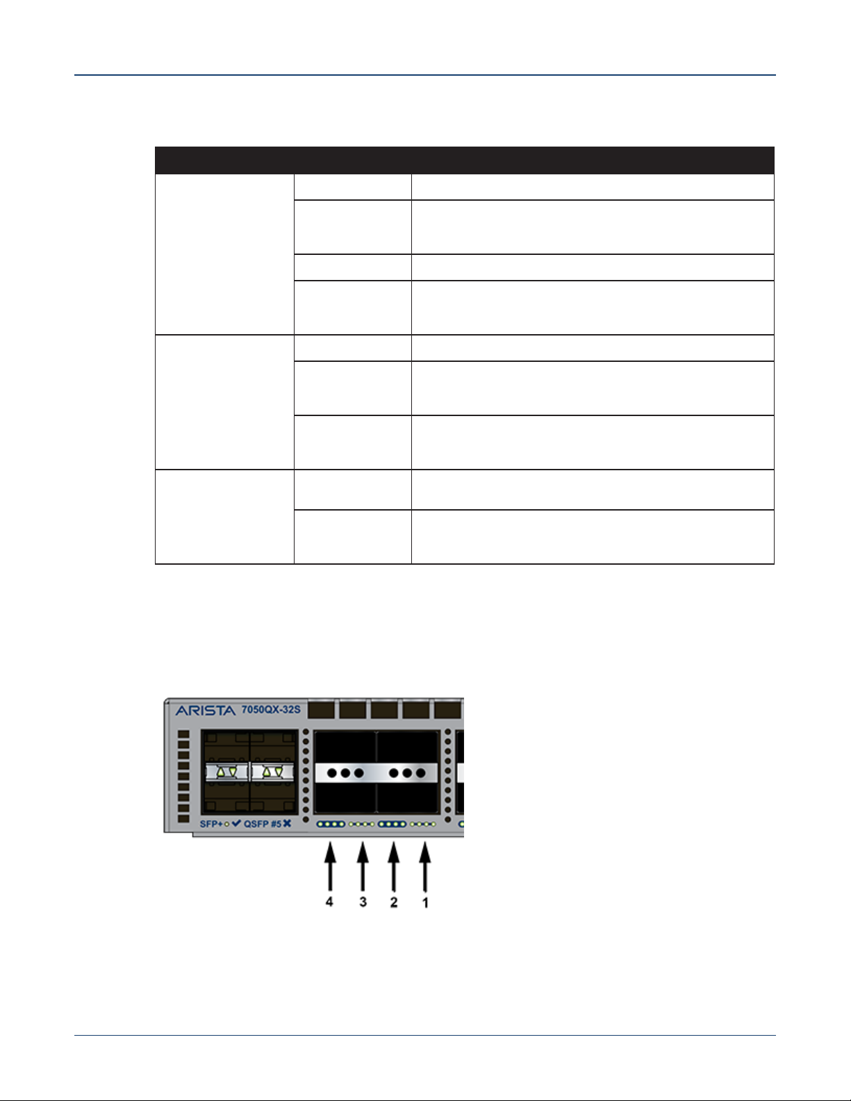
Port LEDs, located in the vicinity of their corresponding ports, provide link and operational status.
Figure A-3 displays the Port LED location on the DCS-7050QX-32S switch.
Figure A-3: Port LEDs
1 Port 4 LEDs 3 Port 2 LEDs
2 Port 3 LEDs 4 Port 1 LEDs
32 Quick Start Guide: 7280 Series 1 RU-Gen 3 Data Center Switches
Page 37
Appendix A: Status Indicators Rear Status Indicators
Table A-2 provides status conditions that correspond to port LED states. Port LED behavior for QSFP+
and SFP+ ports is consistent.
Table A-2 Port LED States (Front)
LED State Status
Off Port link is down.
Green Port link is up.
Yellow Port is software disabled.
Flashing Yellow Port failed diagnostics.
A.2 Rear Status Indicators
Fan and power supply modules are accessed from the rear panel. Each fan and power supply module
contains an LED that reports the module status.
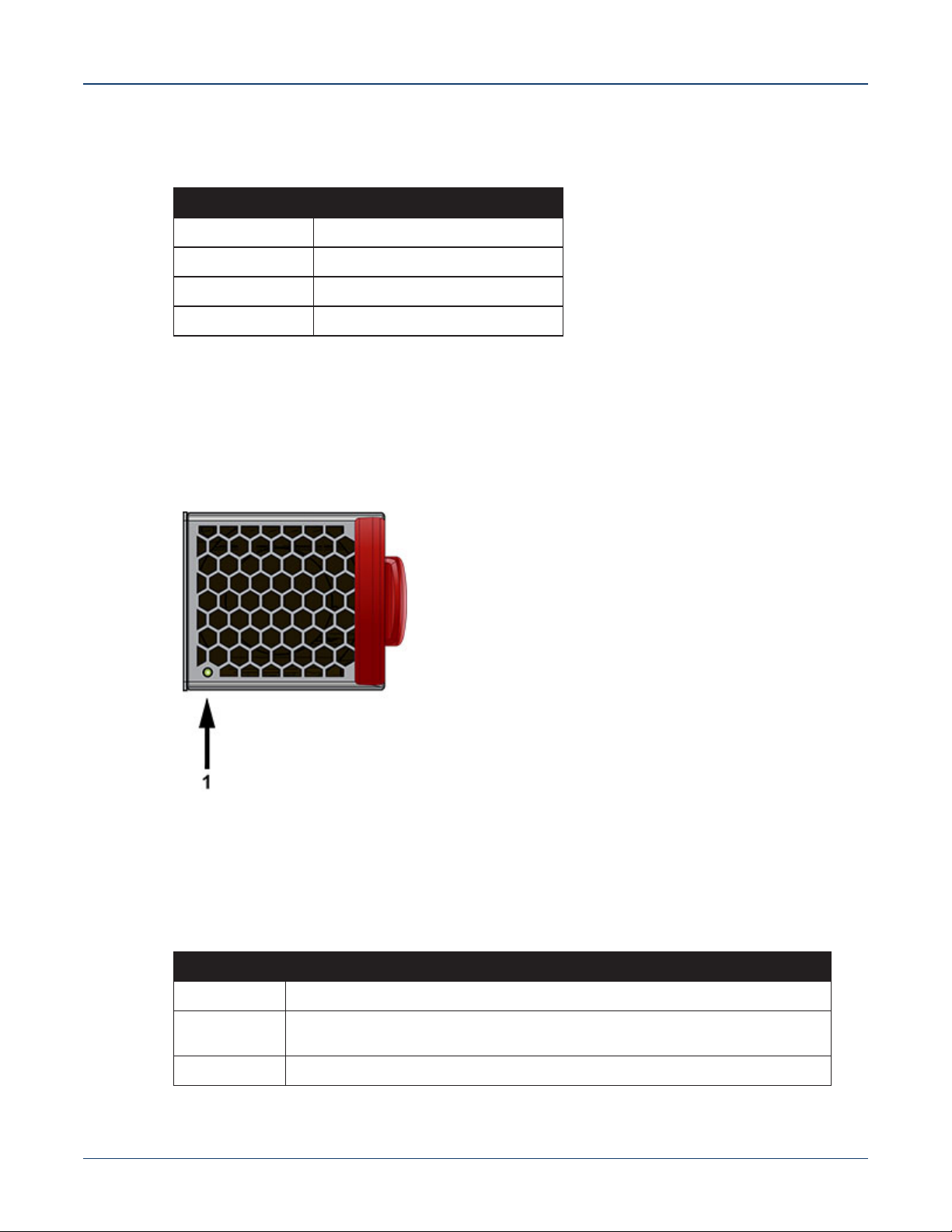
Fan Status LEDs are on the fan modules, as displayed in Figure A-4.
Figure A-4: Fan Status LED
1 Fan module status LED
Table A-3 provides status conditions that correspond to fan status LED states.
Table A-3 Fan Status LED States (Rear)
LED State Status
Off The fan module is not detected. If it is inserted, it may not be seated properly.
Green The fan is operating normally. This LED state is exclusive to its fan module, and
Red The fan has failed.
Quick Start Guide: 7280 Series 1 RU-Gen 3 Data Center Switches 33
independent of the states of its neighboring fans and power supplies.
Page 38
Rear Status Indicators Appendix A: Status Indicators
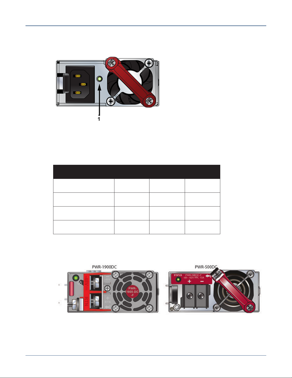
The AC Power Supply Status LEDs are on the power supply modules, as displayed in Figure A-5.
Figure A-5: AC Power Supply Status LED
1 Power supply status LED
Table A-4 provides status conditions that correspond to the AC power supply status LED states.
Table A-4 AC Power Supply Status LED States (Rear)
Power Supply State
Input power present
PWR-500AC-F
PWR-500AC-R
Green Green Green
PWR-745AC-F
PWR-745AC-R
PWR-747AC-F
PWR-747AC-R
Normal operation
Input power present
Yellow Yellow Yellow
Power Supply fault
No Input power Supply
Off Off Off
installed in chassis
Input power present Supply
Green Green Green
not installed in chassis
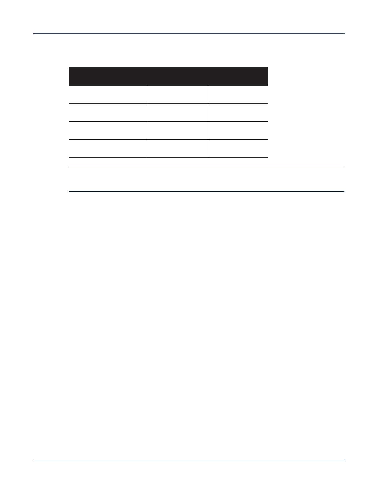
The DC Power Supply Status LEDs are on the power supply modules, as displayed in Figure A-6.
Figure A-6: DC Power Supply Status LED
34 Quick Start Guide: 7280 Series 1 RU-Gen 3 Data Center Switches
Page 39
Appendix A: Status Indicators Rear Status Indicators
Table A-5 provides status conditions that correspond to the DC power supply status LED states.
Table A-5 DC Power Supply Status LED States (Rear)
Power Supply State
Input power present
Normal operation
Input power present
Power Supply fault
No Input power
Supply installed in chassis
Input power present Supply
not installed in chassis
PWR-500DC-F
PWR-500DC-R
Green Green
Blinking Yellow Blinking Yellow
Off Off
Blinking Yellow Blinking Yellow
PWR-1900DC
Note You can narrow down the error condition by logging in to the switch to view the specific device state.
Refer to the Arista User Manual’s Switch Environment Control chapter, under the topic Viewing
Environment Status, for further information on the show environment commands.
Quick Start Guide: 7280 Series 1 RU-Gen 3 Data Center Switches 35
Page 40

Rear Status Indicators Appendix A: Status Indicators
36 Quick Start Guide: 7280 Series 1 RU-Gen 3 Data Center Switches
Page 41
Parts List
Each switch provides an accessory kit that contains parts that are required to install the switch. This
appendix lists the installation parts contained in the switch accessory kit.
B.1 Rack Mount Parts
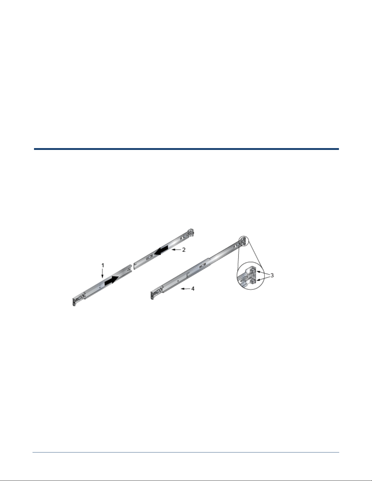
B.1.1 Four-Post Rack Mount Parts
Figure B-1: Four-Post Rack Mount Parts
Appendix B
1 Rail-slide
2 Rail-rod
3 Rack plugs (detail)
4 Rail (assembled)
Quick Start Guide: 7280 Series 1 RU-Gen 3 Data Center Switches 37
Page 42
Cables Appendix B: Parts List
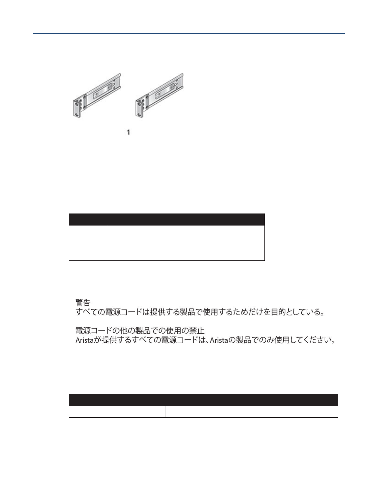
B.1.2 Two-Post Rack Mount Parts
Figure B-2: Two-Post Rack Mount Parts
1 Two-post rack mount
parts
B.2 Cables
Quantity Description
2 Power cables: IEC-320/C13-C14, 13 A, 250 V
1 RJ-45 Patch Panel Cable
1 RJ-45 to DB9 Adapter Cable
Warning All provided power cables are for use only with Arista products.
B.3 Ground Extender Kit (Optional)
SKU Description
KIT-GND-EXT-1RU
1. Available only for certain devices.
38 Quick Start Guide: 7280 Series 1 RU-Gen 3 Data Center Switches
1
Ground extender kit for NEBS compliance
Page 43
Appendix C
Front Panel
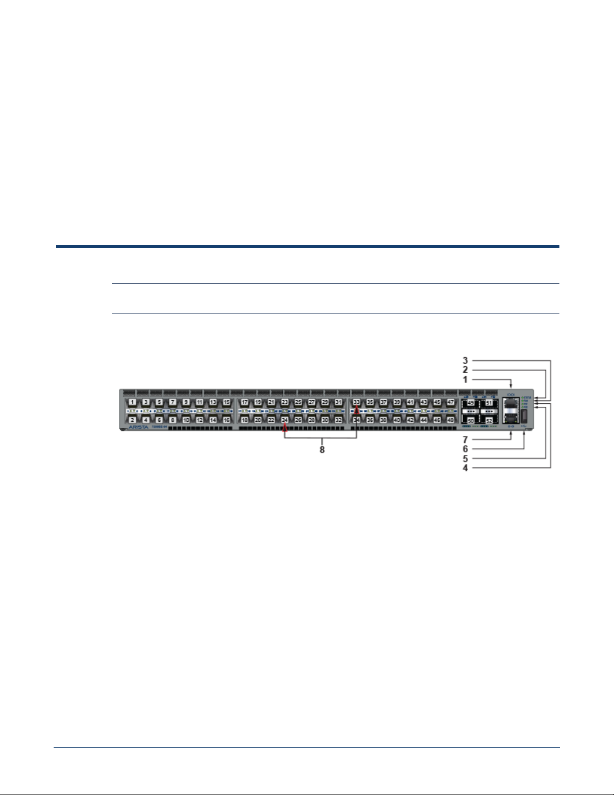
This appendix displays the front panel of all switches covered by this guide.
Note All devices are designed to fit into a 19” rack. The appearance may be different than those shown based
on PSU and fan modules used.
Figure C-1: DCS-7280SE-64
1 Console port (serial) 4 Power supply 1 status LED 7 Ethernet Management port
2 System status LED 5 Power supply 2 status LED 8 Port numbers
3 Fan status LED 6 USB port
Quick Start Guide: 7280 Series 1 RU-Gen 3 Data Center Switches 39
Page 44
Appendix C: Front Panel
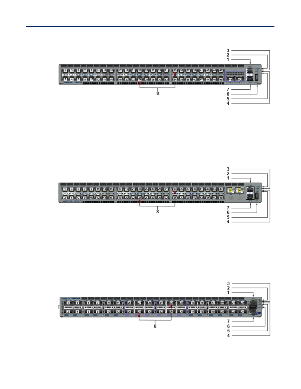
Figure C-2: DCS-7280SE-68
1 Console port (serial) 4 Power supply 1 status LED 7 Ethernet Management port
2 System status LED 5 Power supply 2 status LED 8 Port numbers
3 Fan status LED 6 USB port
Figure C-3: DCS-7280SE-72
1 Console port (serial) 4 Power supply 1 status LED 7 Ethernet Management port
2 System status LED 5 Power supply 2 status LED 8 Port numbers
3 Fan status LED 6 USB port
Figure C-4: DCS-7280QR-C36
40 Quick Start Guide: 7280 Series 1 RU-Gen 3 Data Center Switches
Page 45
Appendix C: Front Panel
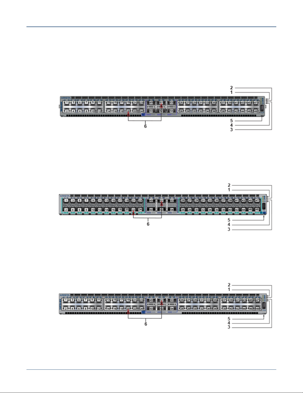
1 Console port (serial) 4 Power supply 1 status LED 7 Ethernet Management port
2 System status LED 5 Power supply 2 status LED 8 Port numbers
3 Fan status LED 6 USB port
Figure C-5: DCS-7280TR-48C6
1 System status LED 3 Power supply 1 status LED 5 USB port
2 Fan status LED 4 Power supply 2 status LED 6 Port numbers
Figure C-6: DCS-7280SR2A-48YC6
1 System status LED 3 Power supply 1 status LED 5 USB port
2 Fan status LED 4 Power supply 2 status LED 6 Port numbers
Figure C-7: DCS-7280TRA-48C6
Quick Start Guide: 7280 Series 1 RU-Gen 3 Data Center Switches 41
Page 46
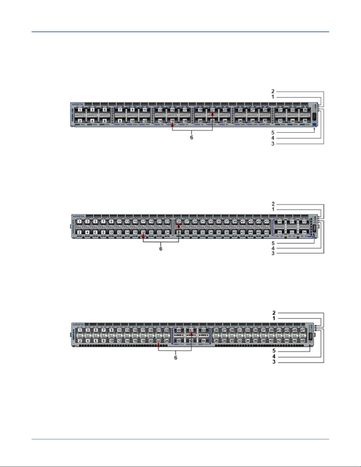
1 System status LED 3 Power supply 1 status LED 5 USB port
2 Fan status LED 4 Power supply 2 status LED 6 Port numbers
Figure C-8: DCS-7280QRA-C36S
1 System status LED 3 Power supply 1 status LED 5 USB port
2 Fan status LED 4 Power supply 2 status LED 6 Port numbers
Figure C-9: DCS-7280SRAM-48C6
Appendix C: Front Panel
1 System status LED 3 Power supply 1 status LED 5 USB port
2 Fan status LED 4 Power supply 2 status LED 6 Port numbers
Figure C-10: DCS-7280SR-48C6
1 System status LED 3 Power supply 1 status LED 5 USB port
2 Fan status LED 4 Power supply 2 status LED 6 Port numbers
42 Quick Start Guide: 7280 Series 1 RU-Gen 3 Data Center Switches
Page 47
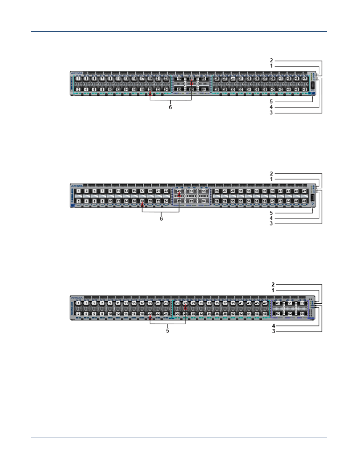
Appendix C: Front Panel
Figure C-11: DCS-7280SR2-48YC6
1 System status LED 3 Power supply 1 status LED 5 USB port
2 Fan status LED 4 Power supply 2 status LED 6 Port numbers
Figure C-12: DCS-7280SRA-48C6
1 System status LED 3 Power supply 1 status LED 5 USB port
2 Fan status LED 4 Power supply 2 status LED 6 Port numbers
Figure C-13: DCS-7280SR2K-48C6
1 System status LED 3 Power supply 1 status LED 5 Port numbers
2 Fan status LED 4 Power supply 2 status LED
Quick Start Guide: 7280 Series 1 RU-Gen 3 Data Center Switches 43
Page 48
Appendix C: Front Panel
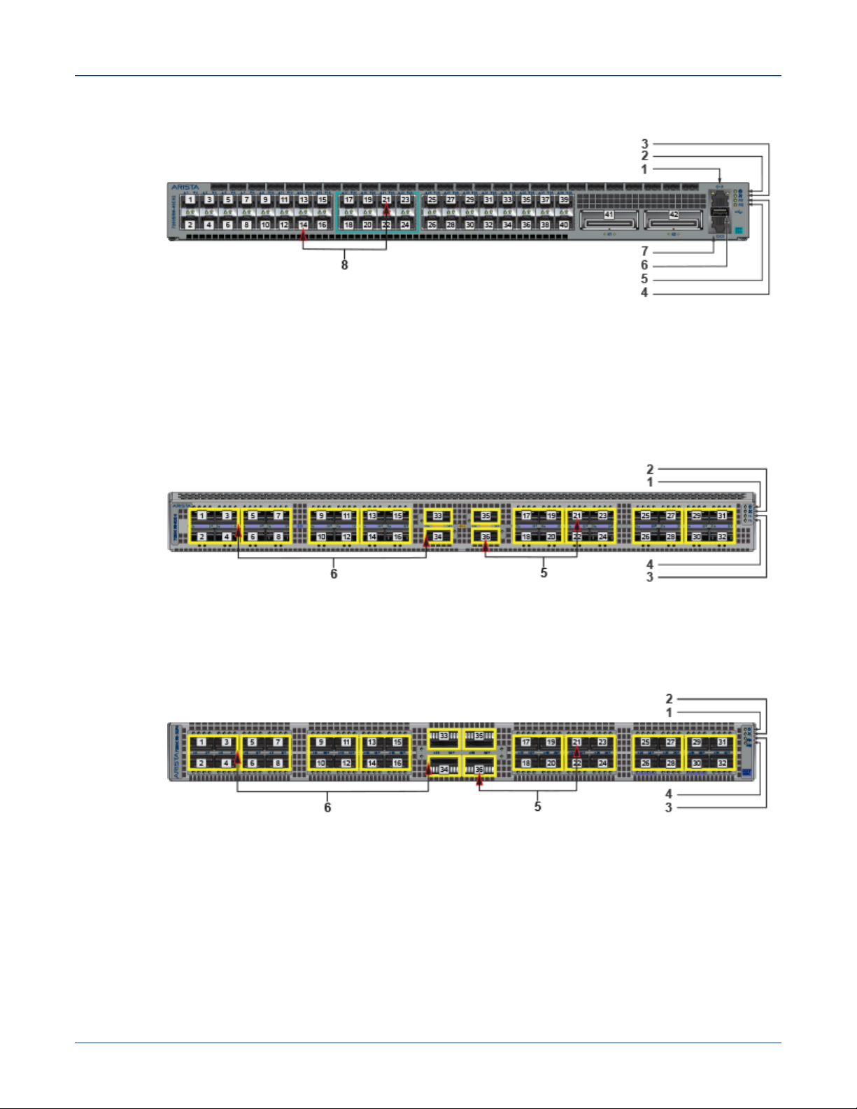
Figure C-14: DCS-7280SRM-40CX2
1 Ethernet Management port 4 Power supply 1 status LED 7 Console port (serial)
2 System status LED 5 Power supply 2 status LED 8 Port numbers
3 Fan status LED 6 USB port
Figure C-15: DCS-7280CR3-32D4 and DCS-7280CR3K-32D4
1 System status LED 3 Power supply 1 status LED 5 Port numbers
2 Fan status LED 4 Power supply 2 status LED 6 Port-speed group
Figure C-16: DCS-7280CR3-32P4 and DCS-7280CR3K-32P4
1 System status LED 3 Power supply 1 status LED 5 Port numbers
2 Fan status LED 4 Power supply 2 status LED 6 Port-speed group
44 Quick Start Guide: 7280 Series 1 RU-Gen 3 Data Center Switches
Page 49
Appendix C: Front Panel
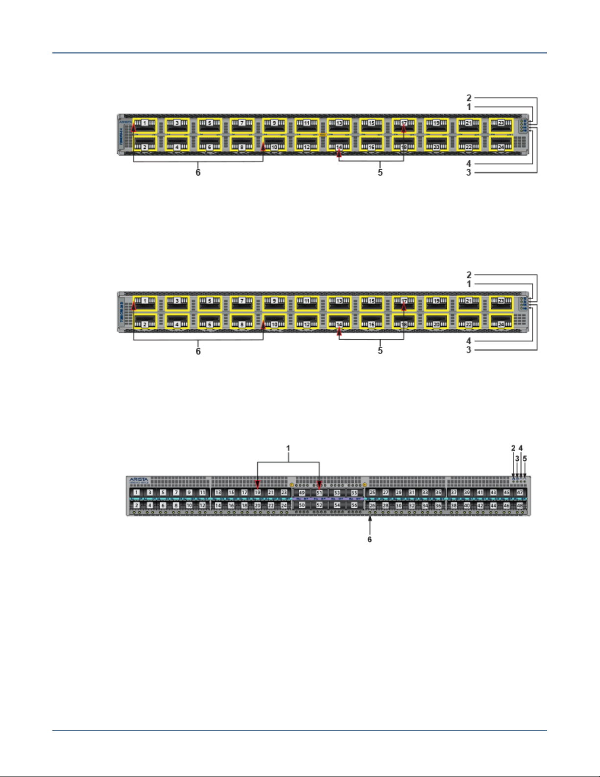
Figure C-17: DCS-7280DR3-24 and DCS-7280DR3K-24
1 System status LED 3 Power supply 1 status LED 5 Port numbers
2 Fan status LED 4 Power supply 2 status LED 6 Port-speed group
Figure C-18: DCS-7280PR3-24 and DCS-7280PR3K-24
1 System status LED 3 Power supply 1 status LED 5 Port numbers
2 Fan status LED 4 Power supply 2 status LED 6 Port-speed group
Figure C-19: DCS-7280SR3-48YC8 and DCS-7280SR3K-48YC8
1 Port numbers 3 Fan status LED 5 Power supply 2 status LED
2 System status LED 4 Power supply 1 status LED 6 Port status LED (port 25)
Quick Start Guide: 7280 Series 1 RU-Gen 3 Data Center Switches 45
Page 50

Appendix C: Front Panel
46 Quick Start Guide: 7280 Series 1 RU-Gen 3 Data Center Switches
Page 51
Appendix D
Rear Panel
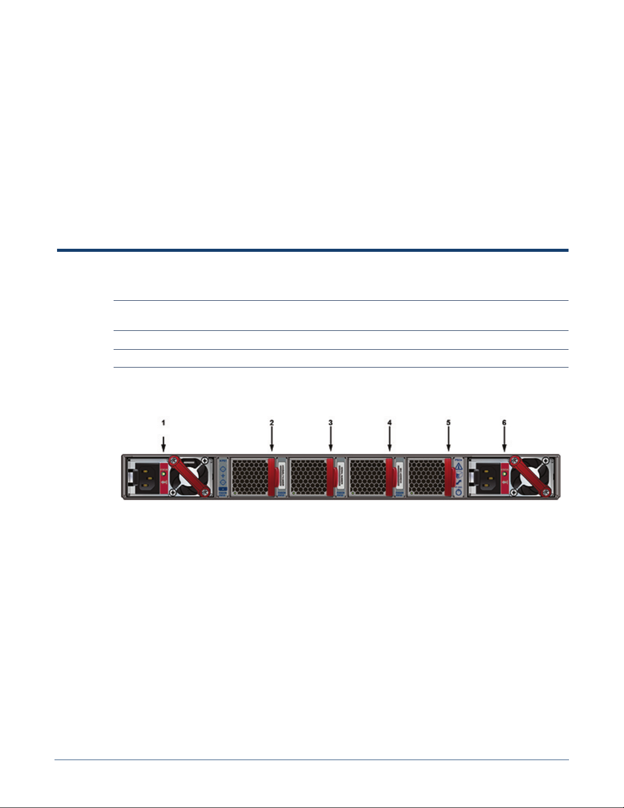
All switches covered by this guide use one of the two rear panels shown below. Depending on the
installed power supply module, the appearance could be different from those shown.
Note All devices are designed to fit into a 19” rack. The appearance may be different than those shown based
on PSU and the modules used.
Note Handle color indicates airflow direction.
Figure D-1: Rear Panel for Models with Management Ports in the Front
1 Power supply 1 4 Fan module 3
2 Fan module 1 5 Fan module 4
3 Fan module 2 6 Power supply 2
Quick Start Guide: 7280 Series 1 RU-Gen 3 Data Center Switches 47
Page 52
Appendix D: Rear Panel
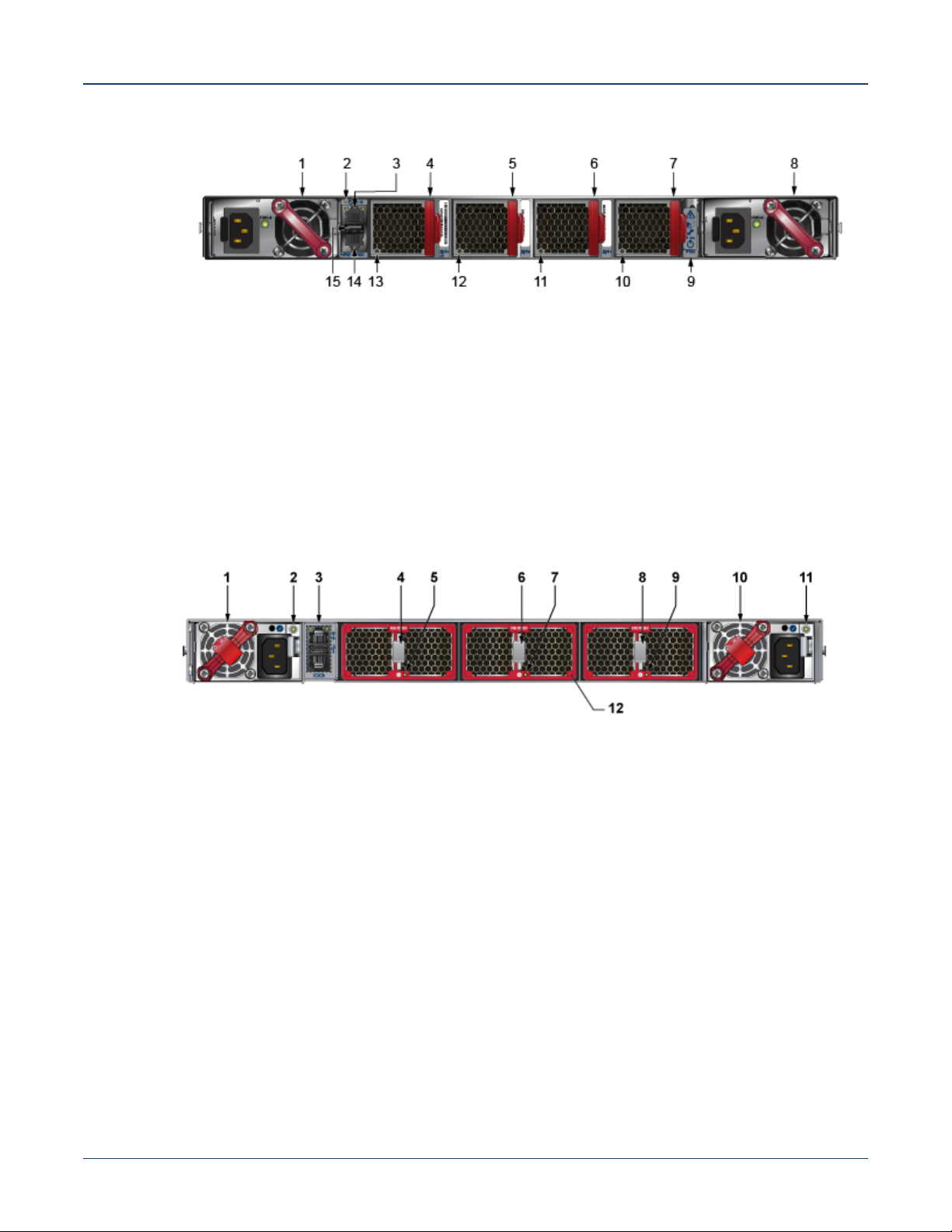
Figure D-2: Rear Panel for Models with Management Ports in the Rear
1 Power supply module 1 6 Fan module 3 11 Fan module 3 status LED
2 System status LED 7 Fan module 4 12 Fan module 2 status LED
3 Ethernet management
8 Power supply module 2 13 Fan module 1 status LED
port
4 Fan module 1 9 Earth grounding pad 14 Console serial port
5 Fan module 2 10 Fan module 4 status LED 15 USB port
Figure D-3: Rear Panel for Models with Management Ports in the Rear and Dual-fan Modules
1 Power supply module 1 5 Fan module 1 status LED 9 Fan module 3 status LED
2 Power supply module 1
6 Fan module 2 release 10 Power supply module 2
status LED
3 Management ports 7 Fan module 2 status LED 11 Power supply module 2 status
LED
4 Fan module 1 release 8 Fan module 3 release 12 Fan module bezel
1. Bezel color indicates airflow direction.
1
48 Quick Start Guide: 7280 Series 1 RU-Gen 3 Data Center Switches
Page 53

Appendix E
Maintenance and Field Replacement
E.1 Considerations
• All fans and power supplies are hot swappable.
• The switch can be running while a power supply is being installed or removed, but the power supply
being replaced must not be connected to a power source.
• All slots must be filled or covered with a blank for operation (even though power supply or fans may
not be functional).
• Before you begin, refer to the Arista Networks document Safety Information and Translated Safety
Warnings available at: https://www.arista.com/en/support/product-documentation.
Note Descriptions for the removal and replacement of power supplies and fans are for a representative
power supply or fan. Locations of status indicator LEDs may differ. Refer to the front and rear panel
illustrations of your device to locate the appropriate LED.
E.2 Power Supplies
The following steps are required when removing power supplies from a switch.
Note Only a representative power supply module is shown in Figure E-1. For the location of the power supply
on your switch, refer to Appendix D.
E.2.1 Removing a Power Supply
Step 1 Ground yourself with an ESD wrist strap.
Step 2 Power down the power supply to be removed by disconnecting the AC power cable.
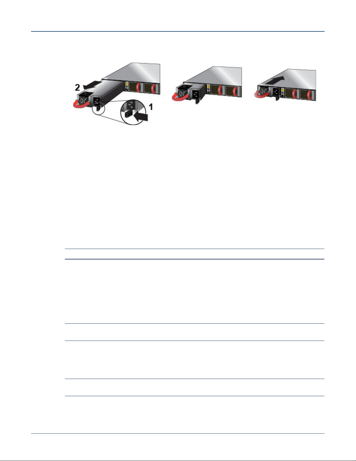
Step 3 Push the power supply release lever and remove the power supply (Figure E-1).
Quick Start Guide: 7280 Series 1 RU-Gen 3 Data Center Switches 49
Page 54
Fan Modules Appendix E: Maintenance and Field Replacement
Figure E-1: Removing and Installing Power Supply
1 Release lever
2 Remove PSU
E.2.2 Installing a Power Supply
You must make space for installing the power supply by removing an existing one (Section E.2.1).
Step 1 Remove the replacement power supply from its packaging.
Step 2 Slide the new power supply into the empty slot.
Step 3 Slide the new power supply into the switch until the power supply is fully seated and the
release lever snaps into place (Figure E-1).
Step 4 Connect the power cord to the power supply.
Step 5 Verify the LED(s) on the power supply.
Note The Power Supply status LED should be a steady green for normal operation.
Step 6 Verify the new power supply operation by issuing the show environment power command.
switch#show environment power
The output of the command will list the power supplies in operation and should include the one you
replaced.
E.3 Fan Modules
Note Hot swap fans within 30 seconds to prevent the switch from overheating. Ensure that the module you
are replacing matches those already installed in the switch.
E.3.1 Removing a Fan Module
The following steps are required when removing or replacing fans from a switch.
Note Only a representative fan module is shown in Figure E-2. For the location of the fan modules on your
switch, refer to Appendix D.
Step 1 Ground yourself with an ESD wrist strap.
50 Quick Start Guide: 7280 Series 1 RU-Gen 3 Data Center Switches
Page 55
Appendix E: Maintenance and Field Replacement Fan Modules
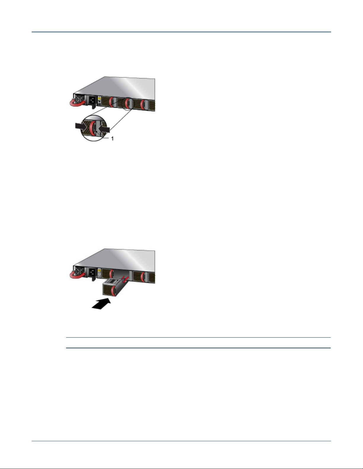
Step 2 Push the fan module release lever and slide the fan module out of the switch (Figure E-2).
Figure E-2: Removing Fan Module
1 Release lever
E.3.2 Installing a Fan Module
You must make space for installing the fan module by removing an existing one (Section E.3.1).
Step 1 Remove the replacement fan from its packaging.
Step 2 Slide the new fan module into the switch until the module is fully seated and the release lever
snaps into place (Figure E-3).
Figure E-3: Inserting Fan Module
Step 3 Verify that the fan module is working normally.
Note The fan module status LED should be a steady green for normal operation.
Quick Start Guide: 7280 Series 1 RU-Gen 3 Data Center Switches 51
Page 56

Fan Modules Appendix E: Maintenance and Field Replacement
52 Quick Start Guide: 7280 Series 1 RU-Gen 3 Data Center Switches
Page 57
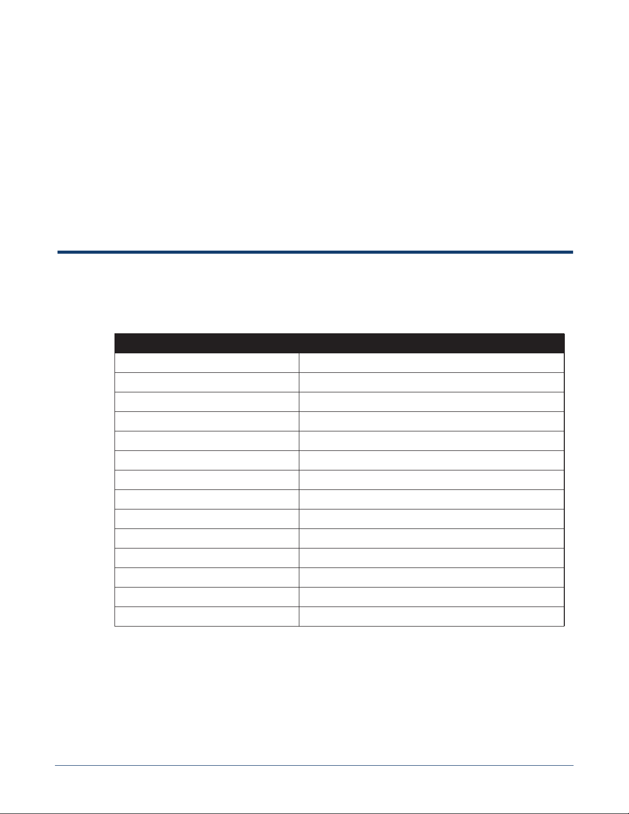
Regulatory Model Numbers
This appendix lists the regulatory model numbers (RMNs), where applicable, for the product models
for the switches described in this document.
Table F-1 Regulatory Model Numbers and Product Numbers
Regulatory Model Number (RMN) Product Number(s)
AN1504 DCS-7280SR-48C6
AN1506 DCS-7280TR-48C6
Appendix F
AN1508 DCS-7280QR-C36
AN1604 DCS-7280QRA-C36S
AN1608 DCS-7280TRA-48C6
AN1615 DCS-7280SR2A-48YC6
AN1623 DCS-7280SRAM-48C6
AN1701 DCS-7280SR2K-48C6
AN1626 DCS-7280SRM-40CX2
AN1708 DCS-7280PR3-24, DCS-7280PR3K-24
AN1730 DCS-7280DR3-24, DCS-7280DR3K-24
AN1715 DCS-7280CR3-32P4, DCS-7280CR3K-32P4
AN1731 DCS-7280CR3-32D4, DCS-7280CR3K-32D4
AN1728 DCS-7280SR3-48YC8, DCS-7280SR3K-48YC8
Quick Start Guide: 7280 Series 1 RU-Gen 3 Data Center Switches 53
Page 58

Appendix F: Regulatory Model Numbers
54 Quick Start Guide: 7280 Series 1 RU-Gen 3 Data Center Switches
Page 59

Taiwan RoHS Information
This appendix provides Taiwan RoHS information for switches covered by this guide.
For Taiwan BSMI RoHS Table, go to https://www.arista.com/assets/data/pdf/AristaBSMIRoHS.pdf.
Appendix G
Quick Start Guide: 7280 Series 1 RU-Gen 3 Data Center Switches 55
Page 60

Appendix G: Taiwan RoHS Information
56 Quick Start Guide: 7280 Series 1 RU-Gen 3 Data Center Switches
 Loading...