

Arista DCS-7050QX-32S, DCS-7280SE-64, DCS-7050TX-72, DCS-7050SX-64, DCS-7050SX-72 Quick Start Manual
...
Quick Start Guide
7000 Series 1 RU – Gen 3
Data Center Switches
(Tool-less)
DCS-7050QX-32S DCS-7050TX-72
DCS-7050SX-64 DCS-7050TX-96
DCS-7050SX-72 DCS-7280SE-64
DCS-7050SX-96 DCS-7280SE-68
DCS-7050TX-48 DCS-7280SE-72
DCS-7050TX-64
Arista Networks
www.arista.com
PDOC-00041-07

Headquarters
Support
Sales
5453 Great America Parkway
Santa Clara, CA 95054
USA
408 547-5500
www.arista.com
408 547-5502
866 476-0000
support@arista.com
408 547-5501
866 497-0000
sales@arista.com
© Copyright 2015 Arista Networks, Inc. The information contained herein is subject to change without notice. Arista Networks
and the Arista logo are trademarks of Arista Networks, Inc in the United States and other countries. Other product or service names
may be trademarks or service marks of others.

Chapter 1: Overview
Chapter 1 Overview
1.1 Scope
This guide is intended for properly trained service personnel and technicians who need to install the
following Arista Networks Data Center Switches:
• DCS-7050QX-32S • DCS-7050TX-48 • DCS-7280SE-64
• DCS-7050SX-64 • DCS-7050TX-64 • DCS-7280SE-68
• DCS-7050SX-72 • DCS-7050TX-72 • DCS-7280SE-72
• DCS-7050SX-96 • DCS-7050TX-96
Important! Only qualified personnel should install, service, or replace this equipment.
1.2 Receiving and Inspecting the Equipment
Upon receiving the switch, inspect the shipping boxes and record any external damage. Retain packing
materials if you suspect that part of the shipment is damaged; the carrier may need to inspect them.
If the boxes were not damaged in transit, unpack them carefully. Ensure that you do not discard any
accessories that may be packaged in the same box as the main unit.
Inspect the packing list and confirm that you received all listed items. Compare the packing list with
your purchase order. Appendix B provides a list of components included with the switch.
1.3 Installation Process
The following tasks are required to install and use the switch:
Step 1 Select and prepare the installation site (Section 2.1).
Step 2 Assemble the installation tools listed in Section 2.2.
Step 3 Attach the mounting brackets and install the switch in an equipment rack (Chapter 3).
Step 4 Connect the switch to the power source and network devices (Chapter 4).
Step 5 Configure the switch (Chapter 5).
Important! Class 1 Laser Product: This product has provisions to install Class 1 laser transceivers which provide
optical coupling to the communication network. Once a Class 1 laser product is installed, the
equipment is a Class 1 Laser Product (Appareil à Laser de Classe 1). The customer is responsible for
selecting and installing the Class 1 laser transceiver and for insuring that the Class 1 AEL (Allowable
Emission Limit) per EN/IEC 6-825, CSA E60825-1, and Code of Federal Regulations 21 CFR 1040 is not
exceeded after the laser transceiver have been installed. Do not install laser products whose class rating
is greater than 1. Refer to all safety instructions that accompanied the transceiver prior to installation.
Only Class 1 laser devices, certified for use in the country of installation by the cognizant agency are to
be utilized in this product.
Important! Ultimate disposal of this product should be in accordance with all applicable laws and regulations.
1.4 Safety Information
Refer to the Arista Networks document Safety Information and Translated Safety Warnings available at:
http://www.arista.com/en/support/docs/eos
7000 Series 1 RU – Gen 3 Quick Start Guide PDOC-00041-06 3

1.5 Obtaining Technical Assistance
Any customer, partner, reseller or distributor holding a valid Arista Service Contract can obtain technical
support in any of the following ways:
• Email: support@arista.com. This is the easiest way to create a new service request.
Include a detailed description of the problem and the output of “show tech-support”.
Chapter 1: Overview
• Web: www.arista.com/en/support
.
A support case may be created through the support portal on our website. You may also download
the most current software and documentation, as well as view FAQs, Knowledge Base articles,
Security Advisories, and Field Notices.
• Phone: 866-476-0000 or 408-547-5502.
Important! No user serviceable parts inside. Refer all servicing to qualified service personnel.
1.6 Specifications
Ta b l e 1 lists the specifications of Arista Data Center switches covered by this guide.
Table 1: Switch Specifications
Size (W x H x D) DCS-7050QX-32S
DCS-7050SX-64, -72. -96
DCS-7050TX-48, -64
DCS-7050TX -72, -96
DCS-7280SE-64, -68, -72
Weight DCS-7050QX-32S
DCS-7050SX-64
DCS-7050SX-72
DCS-7050SX-96
DCS-7050TX-48
DCS-7050TX-64
DCS-7050TX-72
DCS-7050TX-96
DCS-7280SE-64
DCS-7280SE-68
DCS-7280SE-72
Operating Temperature
Storage Temperature
Operating Altitude
Relative Humidity
Power Input (AC Power) all switches 100 - 240 VAC, 6.5 - 3.0 A, 50/60 Hz
Power Draw
(Typical / Maximum)
all switches
all switches
all switches
all switches
DCS-7050QX-32S
DCS-7050SX-64
DCS-7050SX-72
DCS-7050SX-96
DCS-7050TX-48
DCS-7050TX-64
DCS-7050TX-72
DCS-7050TX-96
DCS-7280SE-64
DCS-7280SE-68
DCS-7280SE-72
44.5 x 4.4 x 40.6 cm (19 x 1.75 x 16 inches)
44.5 x 4.4 x 40.6 cm (19 x 1.75 x 16 inches)
44.5 x 4.4 x 40.6 cm (19 x 1.75 x 16 inches)
44.5 x 4.4 x 52.3 cm (19 x 1.75 x 20.6 inches)
44.5 x 4.4 x 52.3 cm (19 x 1.75 x 20.6 inches)
9.1 kg (20 pounds)
8.6 kg (19 pounds)
8.6 kg (19 pounds)
9.1 kg (20 pounds)
7.7 kg (17 pounds)
8.6 kg (19 pounds)
10.0 kg (22 pounds)
10.5 kg (22 pounds)
10.0 kg (22 pounds)
10.1 kg (22 pounds)
10.2 kg (22 pounds)
0° to 40° C (32° to 104° F)
-25° to 70° C (-13° to 158° F)
0 to 3,000 meters (0 to 10,000 feet)
5 to 90%
150 W / 300 W
140 W / 220 W
144 W / 276 W
159 W / 290 W
305 W / 367 W
315 W / 387 W
349 W / 440 W
355 W / 455 W
263 W / 381 W
313 W / 405 W
262 W / 399 W
4 Arista Networks Copyright 2014

Chapter 2: Preparation
MAC ADDRESS
II
IIIIIIIIIIIIIIIIIIIIIIIIIIIIIIII
I
SERIAL NUMBER
IIIIIIIIIIIIIIIIIIIIIIIIIIIIIIIIIII
ASSEMBLY NUMBER
IIIIIIIIIIIIIIIIIIIIIIIIIIIIIIIIIII
Fan Module
Handle
Module 1
Airflow Direction
Power Supply
Module 1
Airflow Direction
Power Supply
Module 2
Fan Module
Handle
Module 2
Fan Module
Handle
Module 3
Fan Module
Handle
Module 4
Chapter 2 Preparation
2.1 Site Selection
The following criteria should be considered when selecting a site to install the switch:
• Temperature and Ventilation: For proper ventilation, install the switch where there is ample airflow
to the front and back of the switch. The ambient temperature should not go below 0° or exceed 40° C.
Important! To prevent the switch from overheating, do not operate it in an area where the ambient temperature
exceeds 40°C (104°F).
• Airflow Orientation: Determine airflow direction of the four fan modules and two power supply
modules on the rear panel. Fan and power supply module handles indicate airflow direction:
— Blue Handle: Air Inlet module.
— Red Handle: Air Exit module.
Figure 1 displays fan and power supply module locations on the rear panel. Their red handles
indicate that they are air exit modules. Verify that each module has the same airflow direction. Base
the switch orientation on the airflow direction of the modules to assure the air inlet is always
oriented toward the cool aisle:
— Air Exit modules: orient the rear panel toward the hot aisle.
— Air Inlet modules: orient the rear panel toward the cool aisle.
If the airflow direction is not compatible with the installation site, contact your sales representative
to obtain modules that circulate air in the opposite direction.
Figure 1: Airflow Direction Labels
• Rack Space: Install the switch in a 19" rack or cabinet. The switch height is 1 RU. The accessory kit
provides mounting brackets for two-post and four-post racks.
When mounting the switch in a partially filled rack, load the rack from bottom to top, with the
heaviest equipment at the bottom. Load the switch at the bottom if it is the only item in the rack.
7000 Series 1 RU – Gen 3 Quick Start Guide PDOC-00041-06 5

Chapter 2: Preparation
• Power Requirements: Power requirements vary by switch and power supply model. Refer to
Ta b l e 1 for information regarding your specific system.
Two circuits provide redundancy protection. Section 4.2 describes power cable requirements.
Important! The power input plug-socket combination must be accessible at all times; it provides the primary
method of disconnecting power from the system.
• Other Requirements: Select a site where liquids or objects cannot fall onto the equipment and
foreign objects are not drawn into the ventilation holes. Verify these guidelines are met:
— Clearance areas to the front and rear panels allow for unrestricted cabling.
— All front and rear panel indicators can be easily read.
— Power cords can reach from the power outlet to the connector on the rear panel.
Important! All power connections must be removed to de-energize the unit.
2.2 Tools Required for Installation
Each switch provides an accessory kit that contains parts that are required to install the switch. In
addition to the accessory kit, the following tools and equipment are required to install the switch:
Two - Po st R ac k
• Screws or rack mounting nuts and bolts.
• Screwdriver
Four-Post Rack (Toolless)
No additional equipment required.
Four-Post Rack (Conventional)
• Screws or rack mounting nuts and bolts.
• Screwdriver
Accessory kit does not include screws for attaching the switch to the equipment rack. When installing
the switch into an equipment rack with unthreaded post holes, nuts are also required to secure the
switch to the rack posts.
2.3 Electrostatic Discharge (ESD) Precautions
Observe these guidelines to avoid ESD damage when installing or servicing the switch.
• Assemble or disassemble equipment only in a static-free work area.
• Use a conductive work surface (such as an antistatic mat) to dissipate static charge.
• Wear a conductive wrist strap to dissipate static charge accumulation.
• Minimize handling of assemblies and components.
• Keep replacement parts in their original static-free packaging.
• Remove all plastic, foam, vinyl, paper, and other static-generating materials from the work area.
• Use tools that do not create ESD.
6 Arista Networks Copyright 2014
Chapter 3: Rack Mounting the Switch
Rear mount
Front mount
Center mount
Front bracket hole does not lock into pin
Rear bracket hole does not lock into pin
Chapter 3 Rack Mounting the Switch
Important! The rack mounting procedure is identical for all switches covered by this guide. Illustrations in this
chapter depict the mounting of a DCS-7050QX-32S switch.
• Section 3.1 provides instructions for mounting the switch in a two-post rack.
• Section 3.2 provides instructions for mounting the switch in a four-post rack.
After completing the instructions for your rack type, proceed to Chapter 4: Cabling the Switch.
3.1 Two-Post Rack Mount
To mount the switch onto a two-post rack, assemble the mounting brackets to the chassis, then attach
the brackets to the rack posts. Two-post accessory kits include the following two-post mounting parts:
• 2 three-hole mounting brackets
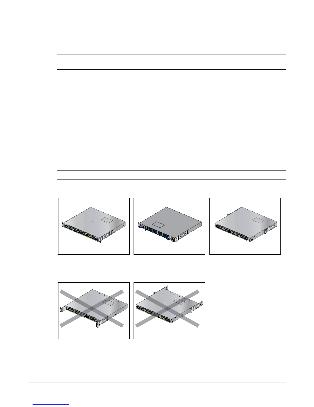
Each chassis side has attachment pins that align with bracket holes. Pin orientation is symmetric and
equidistant, supporing bracket placements where the flange is flush the front switch panel, flush with
the rear panel, or not flush with either panel. Each bracket hole includes a key-opening for placing the
bracket flush with the chassis and then locking it into place.
Important! Attachment pins must be lock all three upper bracket holes.
Figure 2 displays proper bracket mount configuration examples.
Figure 2: Bracket Mount Examples for Two-Post Rack Mount
Figure 3 displays improper bracket mount configuration examples.
Figure 3: Improper Bracket Mount Examples for Two-Post Rack Mount
7000 Series 1 RU – Gen 3 Quick Start Guide PDOC-00041-06 7
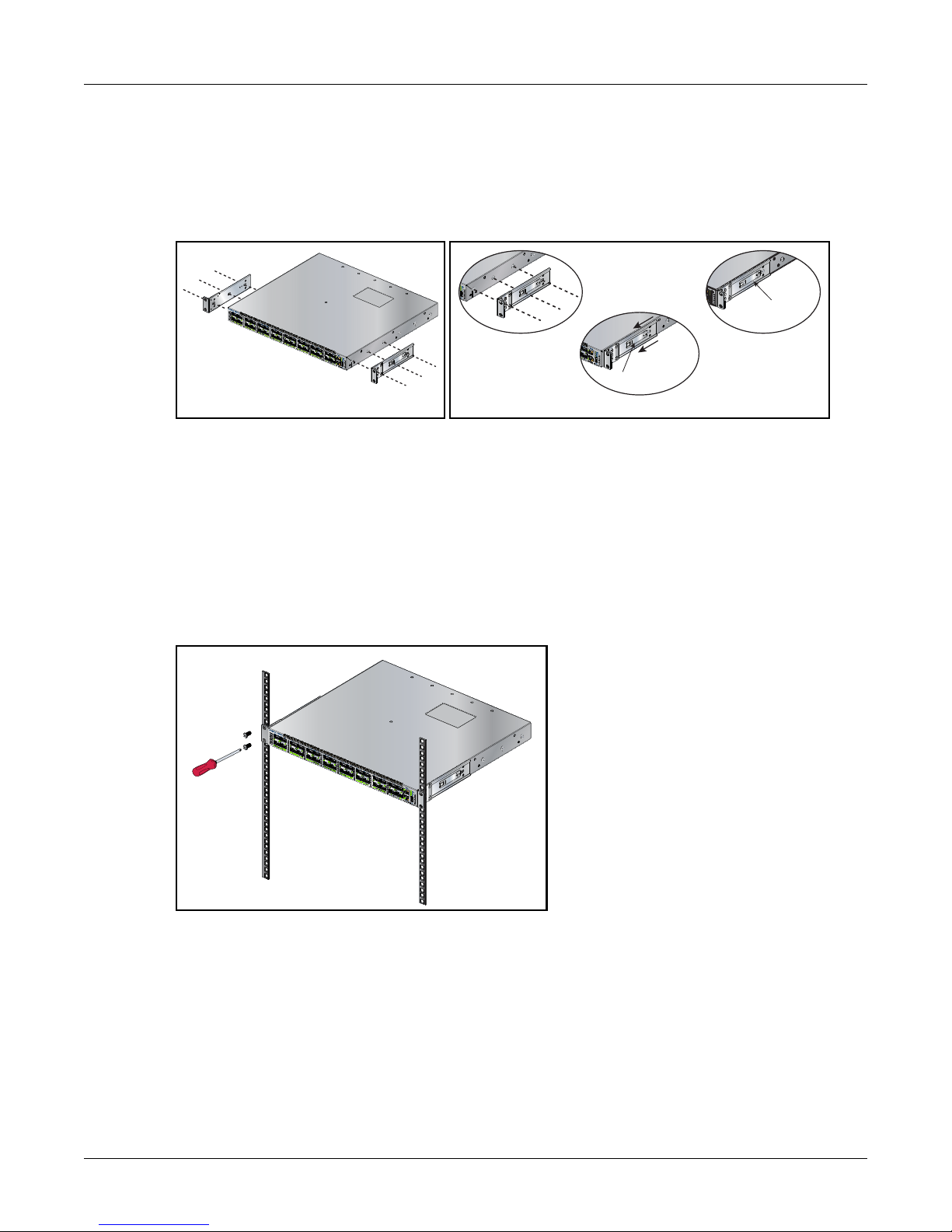
3.1.1 Attaching Mounting Brackets to the Chassis
Attaching the brackets: Front mount
Bracket Clip
Step 3
Bracket Clip
Step 2
Step 1
This procedure attaches mounting brackets to the switch chassis (Figure 4).
Step 1 Align the mounting brackets with the attachment pins to obtain the desired mounting position.
Step 2 Place the bracket flush on the chassis with attachment pins protruding through key-openings.
Step 3 Slide the bracket toward the front flange until the bracket clip locks with an audible click.
Figure 4: Attaching the Mounting Brackets to the Switch Chassis
To remove the mounting bracket from the chassis, lift the front edge of the mounting bracket clip with
a flathead screwdriver and slide the bracket away from the front flange (opposite from the installation
direction).
Chapter 3: Rack Mounting the Switch
3.1.2 Inserting the Switch into the Rack
This procedure attaches the switch to the rack (Figure 5).
Step 1 Lift the chassis into the rack. Position the flanges against the rack posts.
Figure 5: Inserting the Switch into the Rack
Step 2 Select mounting screws that fit your equipment rack.
Step 3 Attach the bracket flanges to the rack posts.
After completing the two-post rack mount, proceed to Chapter 4: Cabling the Switch.
8 Arista Networks Copyright 2014
 Loading...