

Page 1
USER INSTRUCTION MANUAL
Auto-Darkening Filters
S540
X60V
X54Vi
S450
X60V
X54Di
S240
X35V
X450V
X540V
iDF81
85 Independence Drive, Taunton, MA 02780
TEL: (508) 884-9600 • TOLL FREE: (800) 223-4685 • FAX: (508) 884-9666
ADFILTERS-01-UI Rev C
Page 2
ArcOne®auto-darkening filters protect the user against harmful ultraviolet and infrared rays, both in the
ark and light state. No matter what shade the filter is set to, the UV/IR protection is always there.
d
When used properly, the filter will prevent your eyes from being burned due to optical radiation. User’s
eyes can be severely burned if welding with a damaged lens (cracked, pitted, etc.).
NSI (American National Standards Instititue)
A
protection from optical radiation and impact. For complete safety, additional protection, such as
spectacles or goggles should be worn with welding helmets. Protective clothing and
ccessories such as leather bibs attached to the welding helmet will protect the user from
a
spatter and optical radiation indirectly entering from areas behind the helmet.
NOTE: Not for use in overhead welding.
(American Conference of Governmental Industrial Hygienists) has established a TLV-
ACGIH
TWA of 5mg/m3 for welding fumes. Welding fumes cannot be classified simply. The composition and quantity of both are dependent on the alloy being welded and the process and
electrodes used. Consult an Industrial Hygienists to ensure all your safety needs are being met.
efines all welding helmets as secondary eye
d
Shade
S240, SS240, S450, S540 and XT540: No adjustments; shade is fixed per model shade number.
X450V
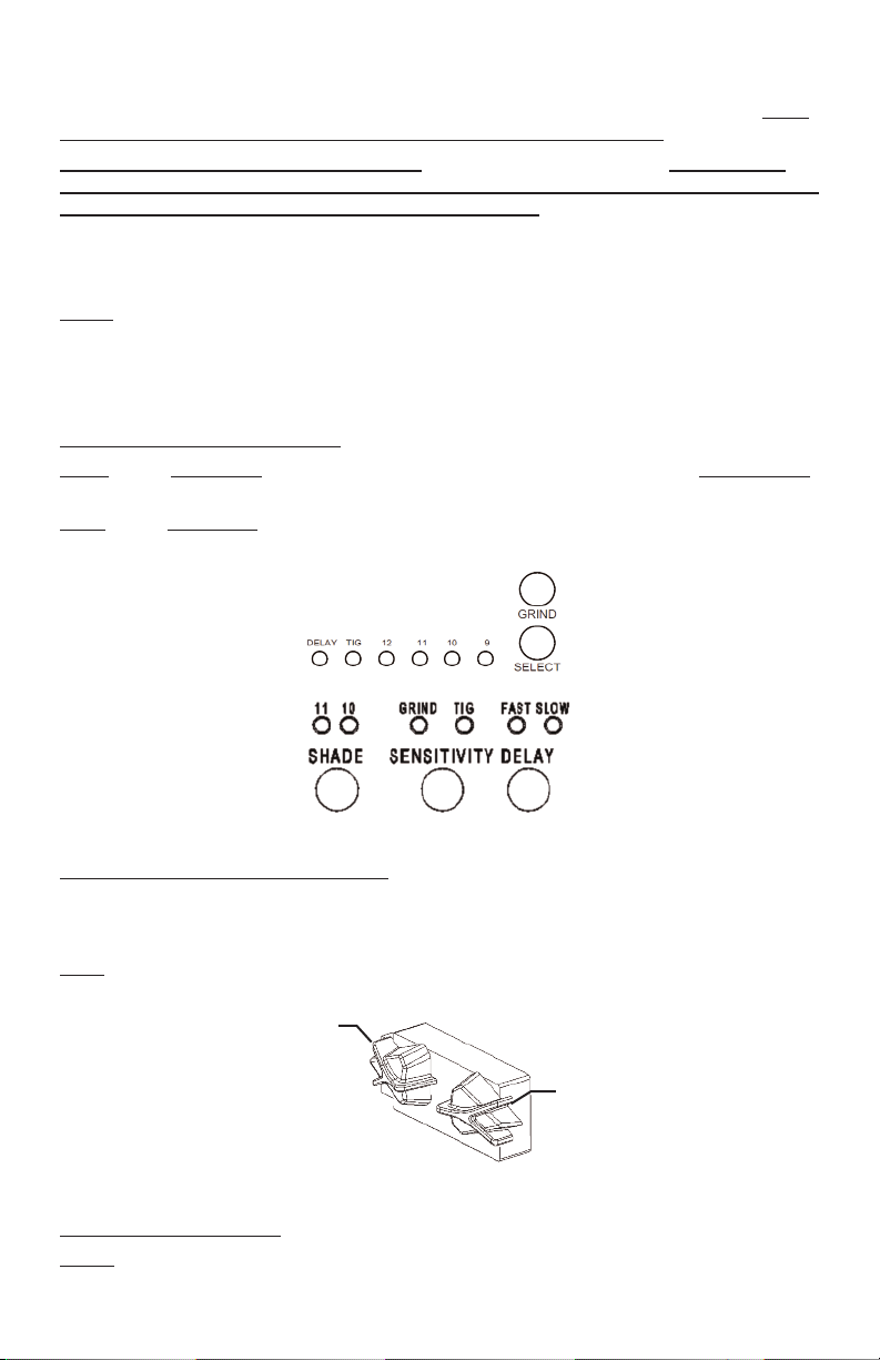
: Press (Do Not Hold) the Select button, an LED will indicate the current setting. Press and hold
the button to change the setting (see Fig. 1).
X54Di
: Press (Do Not Hold) the SHADE button until the LED indicates the desired shade setting
(see Fig. 1).
X450V
C5
X54Di
Figure 1: Controls with LED Indicators
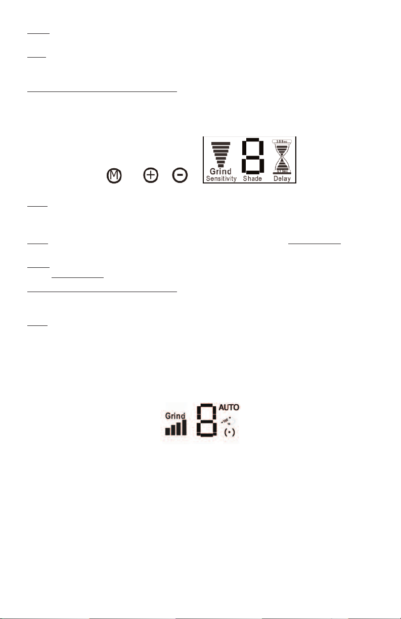
X35V, X540V, X54V, X60V, X81V, and X54Vi
use the “+” and “-” buttons to adjust the shade number (see Fig. 3). Note: the function buttons may be
located to either side of the digital display depending on the model. Refer to the front cover of this manual for the configuration of each model.
iDF81
: Adjust the shade using the shade adjustment knob (see Fig 2) on the helmet, the LCD readout
will indicate the shade number.
Shade
Adjustment
: Press the “M” mode button until “Shade” flashes then
Sensitivity Adjustment
Figure 2: External Controls (iDF81)
Sensitivity and Delay
S240, S450, S540 and XT540: No adjustments; sensitivity and delay are fixed.
SS240:
Press (Do Not Hold) the buttons labeled Sensitivity or Delay to turn that setting on or off.
Delay mode is used in most welding applications except spot welds. Long delay at <20A to keep filter dark.
- 1-
Page 3
X450V: Press and hold the Select button, to change sensitivity from standard sensitivity to TIG; a LED
ill indicate when TIG and/or Delay modes are activated (see Fig 1).
w
X54D
i: Press the SENSITIVITY button to change sensitivity from standard sensitivity to TIG; an LED will
indicate when TIG mode is activated (see Fig 1). Press the DELAY button to change the delay setting;
n LED will indicate either FAST or SLOW. (See Fig 1).
a
35V, X540V,
X
“-” buttons to increase or decrease; more bars equals higher sensitivity. Press “M” button till “Delay”
flashes. Use the “+” and “-” buttons to change delay from 0.1 to 3.5 seconds (see Fig 3). Note: the
unction buttons may be located to either side of the digital display depending on the model. Refer to
f
the front cover of this manual for the configuration of each model.
54V, X60V, X81V, and X54Vi: Press “M” button till “Sensitivity” flashes. Use the “+” and
X
Figure 3: Controls with LCD Readout (X35V, X540V, X54Vi, X54V, X60V and X81V)
iDF81
: Change the sensitivity with external control (see Fig 2). Sensitivity Level is not displayed on
iDF81 LCD readout. Press Delay button to change delay bars from 0.1 to 3.5 seconds (see Fig 4).
Grind
X54Di: Press the SENSITIVITY button until the LED indicates GRIND. Press (DO NOT HOLD) again to
turn off (see Fig 1).
X450V
: Press and hold the GRIND button until the LCD flickers to indicate the change to grind mode.
Press (DO NOT HOLD
X35V, X540V,
flashing, press the “-” button until the word “Grind” appears. Adjust sensitivity until you see at least one
(1) bar to reactivate the lens (see Fig. 3).
iDF81
: Turn sensitivity knob counter-clockwise until it clicks and the LCD readout displays Grind.
(***NOTE: Other modes will not work when in Grind Mode, see Fig 4).
ntelligent Darkening Filter (iDF) Modes (see Fig 4)
I
The iDF comes equiped with two modes: Auto-Variable and iTig. To switch from one mode to the other
Press AND Hold down the Mode button for two seconds. To cycle through modes continue depressing
the Mode button.
) again to turn off grind mode; the LCD will not flicker (see Fig 1).
X54V, X60V, X81V, and X54Vi: Press the “M” button until “Sensitivity” flashes; while
Figure 4: LCD Readout (iDF81)
Auto-Variable Mode: LCD displays “AUTO” (see Fig. 4). Filter automatically responds to the intensity
of the welding arc and sets the filter to the appropriate dark shade. The user can further adjust the dark
shade up or down for comfort while the “(٠)” flashes. The setting will be saved in a memory slot. This
mode has 8 memory slots, one for each shade number 7 thru 14; i.e. shade 7 = memory 1, shade 8 =
memory 2, etc. The user can reset all memory slots by Pressing and holding both Mode and Delay
buttons for two seconds.
iTIG Mode: Upon entering iTIG mode, where LCD displays “TIG” icon and flashing “(٠)” (see Fig. 4),
user first sets the lower desired shade while the “(٠)” flashes. After approximately 5 seconds of not
turning the shade knob the flashing stops and the user can then set the desired upper shade. The user
can reset memory by Pressing and holding both Mode and Delay buttons for two seconds.
- 2-
Page 4

Care and Maintenance
Your new filter requires virtually no maintenance other than periodic cleaning when the lens becomes
irty or clouded from smoke. A
d
by using a soft cloth with soapy water solution, or standard window cleaner. By changing cover plates
frequently you will extend the life of your filter and guarantee the best operation possible. Additional
ront and rear cover plates are available from your A
f
filter in water or solution. Storage Temperature 14 - 100°F (-10 - 38°C).
ARNING! Using the wrong cover plates may damage your product, compromise UV/IR
W
protection, and VOID WARRANTY. Use genuine A
and fit.
DF81:
i
The battery located in the external control center will last 3-6
months depending on usage. When the battery voltage is low, a low
battery symbol will flash in the upper left corner of the digital display
(see Fig.5). Replace with battery of same size (typically AA) and voltage (1.5 V). The lens will not darken with a weak or dead battery.
Special note for XT540 EVA®: The extended viewing area is made of highly polished optical material.
It has been hard coated with a scratch resistant finish; however it is not scratch proof. Clean your
XT540 as directed. Please be careful to use a soft clean cloth or eyeglass wipes. Abrasive particles,
such as those in an unclean cloth, could scratch theh polished surface. Install ARCONE®cover plates on
both sides of the filter to protect from spatter damage and scratches.
RCONE
®
uto-darkening filters are water-resistant and may be cleaned
a
®
RCONE
istributor (see Table 1). Do not submerge
d
®
RCONE
replacement parts to ensure quality
Fig. 5: Low Battery
Indicator
Spatter Protection
SPATTER DAMAGE IS NOT COVERED BY WARRANTY
There are many reasons why spatter can damage the auto-darkening filter. Missing, incorrect,
damaged, or distorted cover plates and excessive spatter build-up in and around the areas where the
cover plates are retained are just a few examples. Any one or combination of these will allow spatter to
enter the filter area and pit the filter glass.
All helmets take a
The Hawk and Eagle Helmets are designed to accept polycarbonate cover plates from the outside of the
helmet without removing other components. This design allows for quick and easy cleaning and cover
plate replacement. The use of an incorrect cover will distort the helmet and result in spatter entering
the filter area.
NOTE: Change your cover plate when it loses its flexibility and/or becomes bowed or distorted. Clean
any build-up from the area where the cover plate is retained.
Flip front designs must use 0.060” thick inner cover plates for protection from particles produced when
chipping or grinding.
A 0.03” thick inside cover plate may be used to protect the inside surface of 5X4 auto-darkening filters.
This size is ideal for digital lenses to allow easy operation of the funtion buttons.
0.040” thick outside cover plate. A nominal 0.060” outside cover plate will not work.
- 3-
Page 5

Figure 6: Exploded Views of Select Helmets
®
5X4 Exploded View
Viper
Hawk®2 x 4 Exploded View
- 4-
Page 6

Vision
®
X4 Exploded View
5
Outside Cover Plate
Helmet Shell
AD Filter
Headgear Assembly
ag Lens (Optional)
M
Inside Cover Plate
Table 1: Parts Selection Guide
Part Number Description
02-OP 0.04”Thick Inside or Outside Cover Plate for 4X5 or 5X4 Helmets
02-OP-AF 0.04”Thick Inside or Outside Anti-fog Cover Plate for 4X5 or 5X4 Helmets
03-OP 0.04”Thick Inside or Outside Cover Plate for 2X4 Helmets
08-IP 0.03”Thick Inside Cover Plate for 4X5 or 5X4 Helmets
02-HG Economical Ratchet Headgear with Cloth Sweatband
06-HG ComfaGear Ratchet Headgear with Deluxe Sweatband
®
SPR-01 Small Springs for Hawk
SPR-02 Large Springs for Viper®, Vision®, and Eagle
Helmets (10 pack)
®
Helmets (10 pack)
For additional parts and accessories, visit our website and view our online brochure at
www.arc1weldsafe.com.
- 5-
Page 7

Trouble Shooting Guide
ontact
C
t has become difficult to see through the filter:
I
echnical Service at
T
(800) 223-4685 i
f any problem below persists after fixing.
®
A
RCONE
• Clean or replace cover plates when they become dirty or discolored.
• Clean auto-darkening filter with soft cloth and soapy water solution or standard window cleaner.
The auto-darkening filter will not darken after striking an arc:
• Clean/replace cover plate. auto-darkening filter sensors and solar panels are unobstructed, clean,
ot broken, or discolored. Cease using this product if problem persists.
n
• Test the auto-darkening filter to a TV or VCR remote (click any button while pointing at front of filter).
The filter should darken momentarily then switch back to the light state. Avoid blocking the solar
panels. Once sure that filter is functional you are ready to begin welding.
• Make sure filter is not in Grind mode.
• Make sure filter settings match application.
• Put into TIG or increase sensitivity setting. Alternatively, try rotating the filter 180 degrees so sensors
and solar panel are located at the bottom. The sensor will have a completely different view of weld.
The auto-darkening filter is slow to darken:
• Colder temperatures will slow the switching speed of an auto-darkening filter. Once the heat from
welding process warms up the components, switching speeds will increase. auto-darkening filters
work best at room temperatures.
The auto-darkening filter goes light or flickers on/off while welding:
• Clean or replace outer clear polycarbonate lens if it becomes soiled or cloudy.
• Check sensors and solar panels are not damaged, dirty, or covered with smoke. Clean filter as
directed.
Flickers on and off sometimes while MIG and TIG welding.
• MIG and TIG applications utilize “GUN” or “Torch” that has a nozzle with the electrode protruding only
slight from it. “Gun” or “Torch” nozzle can block the welding arc from sensors.
The auto-darkening filter stays dark after you stop welding:
• Exceeding the temperature limitations may also cause the LCD to stay dark. Let the filter cool down
and try not to overheat it again by viewing the arc from the side and not directly above or by
increasing the distance the filter is in relationship to the arc. Your filter may remain dark after welding
if you are facing a bright light or the sun. If this is the case either look away or pass your hand
between the source of the light and the sensors. By doing this the light source will be interrupted and
the filter will clear.
The auto-darkening filter has a crack running through the front viewing area:
• UV/IR protection may be compromised resulting in burns caused by ultraviolet or infrared radiation.
Cease using this product if the problem exists and contact
A
RCONE
®
Technical Service.
The auto-darkening filter appears dark in the center and lighter around the edges:
• You are most likely experiencing a common characteristic of an LCD known as angle dependency.
Spatter is causing damage to the filter:
• There are many reasons why spatter can damage the auto-darkening filter. Missing incorrect
damaged, or distorted cover plates, and excessive spatter build-up in and around the area where the
cover plates are retained are just a few examples. Any one or a combination of these will allow
spatter to enter the filter area and pit the filter glass. Do not operate this product if this condition
exists. The UV/IR protection may be compromised. Unfiltered welding light may penetrate through
the filter and may result in severe eye damage and burns.
- 6-
Page 8

LIMITED WARRANTY
®
®
ARCONE
all non-digital auto-darkening filters listed in this manual for a period of two (2) years from the date of
p
are warranted for a period of ninety (90) days. Proof of purchase establishing the date of sale and filter
serial number must be provided, should a warranty claim be submitted. The purchaser’s only remedy
u
exceed the purchase price). This warranty is void in the case of unauthorized modification, tampering,
and damage due to misuse, abuse, inadequate maintenance or improper storage. Some indications of
o
not transferable from the original purchaser to a secondary owner.
responsible for any injury, damage or loss resulting either directly or indirectly from the use or misuse of
this product. This limited warranty is exclusive and is in lieu of any other warranty implied either oral or
written. Please read the instruction manual carefully to avoid certain situations which may void this limited
warranty. See the enclosed Warranty Registration Card for additional details.
warrants all digital auto-darkening filters listed in this manual for a period of three (3) years and
urchase against all manufacturing defects resulting from materials or workmanship. Other components
®
A
nder this limited warranty shall be limited to
perator abuse include, but are not limited to, spatter, chips, dents or cracks.This limited warranty is
RCONE
ole option to repair, replace or refund (not to
s
®
ARCONE
shall in no event be liable or
RETURN PROCEDURE
Please do not contact the distributor or retailer from whom you purchased the filter.
1. Remove the auto-darkening filter from the helmet. Record the model number and serial
number which are located on the filter edge or back. Also record the date of purchase from
your sales receipt.
®
A
2. Contact
RCONE
Technical Service (800-223-4685) for a Return Authorization Number.
3. Return the lens only, freight pre-paid, in a box with packaging material to prevent damage,
no envelopes, please. Reference the Return Authorization Number on the box and any
accompanying paperwork. Include your contact information and return address (no PO
Boxes, please).
Figure 8: Serial Number Location
SERIAL NUMBER
Located on
any narrow
edge of lens.
You may need
to remove
lens from
helmet in
order to view.
®
RCONE
A
TEL: (508) 884-9600 • TOLL FREE: (800) 223-4685 • FAX: (508) 884-9666
PLEASE VISIT OUR WEBSITE AND REGISTER: www.arc1weldsafe.com
is a Division of A.C.E. International Company
85 Independence Drive, Taunton, MA 02780
- 7-
 Loading...