

Page 1
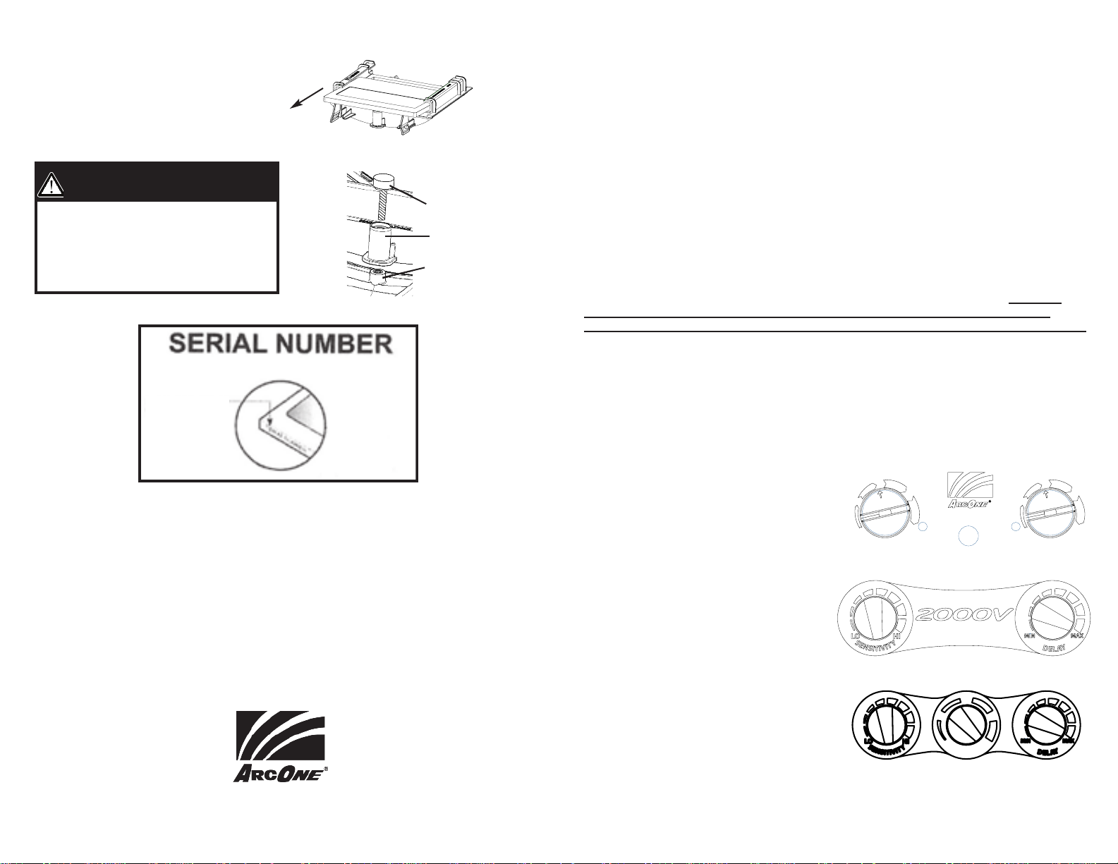
Filter Removal Instructions
D E L A Y / GR I N D
L O
H I
99
11 00
11 11
11 22
11 33
1000
S E N S I T I V I T Y S H A D E
G R I N D D E L A Y
FFccFF
9
10
11
12
13
S
H
A
D
E
Printing:
1. Rotate Page 2
2. Print as 2-sided Letter, black
and white
Removable Filter Holder
1. Grab filter by top and bottom edge
2. Pull up on bottom edge of filter and slide out
of the bottom of the filter holder (Fig. 6)
Critical Installation Warning!
Helmet impact rating Z87+ with Thumb
Screw installed. Helmet rating Z87 without
thumb screw. For Z87+ make sure Filter
Holder Center Tab is secured to the Welding
Helmet Centering Pin with Thumb Screw (See
Figure 7). Do not over tighten
Located along filter
edge or back
Slide
Figure 6
Figure 7
Thumb Screw
Filter Holder Boss
Centering Pin with
Threaded Insert
USER INSTRUCTION MANUAL
CARRERA HELMET WITH
AUTO-DARKENING FILTER
Preparations for Use
Filters:
Before you begin welding always inspect your filter to ensure it is not damaged.
WARNING, never begin welding without first checking to see if the correct front
protection plate is in place, the filter is secured properly in the filter holder, and the
filter holder secured in the helmet. Failure to protect the welding filter or install the
filter / filter holder correctly may cause damage and become a safety hazard should
the UV/IR protection be compromised from spatter or cracks from impact. DAMAGE
CAUSED BY ABUSE SUCH AS EXCESSIVE TEMPERATURES, CRACKS FROM IMPACT,
AND PITTING FROM SPATTER CAUSED BY POOR MAINTENANCE WILL VOID WARRANTY.
Welding Helmets:
WARNING, other safety precautions such as protective clothing, adequate ventilation,
breathing protection, such as a Clean Air FlowTMor equal, fire extinguisher, and
protection for co-workers, should also be considered.
Technical Information / Use
Warranty and Service Information
®
ArcOne
warrants all auto-darkening filters covered by this manual for two (2) years from the date of purchase against manufacturing defects resulting from materials or workmanship. Proof of purchase establishing the date of sale and filter serial number must be provided, should a warranty claim be
submitted. The purchaser’s only remedy under this limited warranty shall be limited to
tion to repair, replace or refund (not to exceed the purchase price). This limited warranty is void in the case
of unauthorized modification, tampering, and damage due to misuse, abuse, inadequate maintenance or
improper storage. This limited warranty is not transferable from the original purchaser to a secondary owner.
®
ArcOne
shall in no event be liable or responsible for any injury, damage or loss
resulting either directly or indirectly from the use or misuse of this product. This limited warranty is
exclusive and is in lieu of any other warranty implied either oral or written. Please read the instruction manual carefully to avoid certain situations which may void this limited warranty.
Troubleshooting or Return Authorization, call (800) 223-4685 or visit www.arc1weldsafe.com
85 Independence Drive, Taunton, MA 02780
Limited Warranty
(800) 223-4685
ArcOne’s
sole op-
Filters:
Warning: Severe burns are possible with a
damaged lens (cracks, pits, holes, etc.).
Do not use damaged lens. Optical radiation
can possibly enter in from behind the
helmet from other welders welding in the
immediate area.
Filter Specific Features
1000FcF (See Figure 1): Shade and Sensitivity are
adjusted using the knobs on the back of the filter.
Change the Delay by quickly pressing and releasing the Delay/Grind button. The red delay LED will
turn on for Delay. Press and release the
Delay/Grind button again to turn off. To activate
the grind mode, press and hold down the
Delay/Grind button until the red Grind LED turns
on. Deactivate Grind mode by quickly pressing
and releasing the Delay/Grind button again. Grind
LED turns off.
2000V: Shade knob is on the outside of the helmet. Sensitivity and Delay are adjusted using the
knobs on the back of the filter (See Figure 2). This model does not have Grind mode.
2500V: Same as 2000V with the addition of shade to the back. (See Figure 3)
CARRERA-02-UI REV C
Figure 1
Figure 2
Figure 3
Page 2
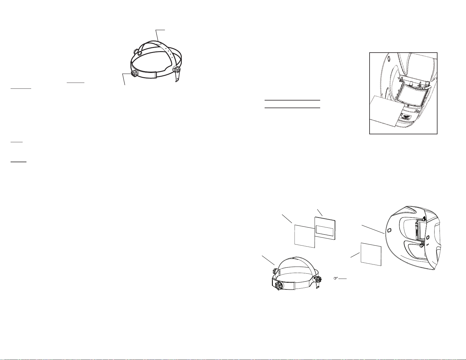
Technical Use
A
djust Height: Snap Out/
S
lide/ Snap In
Adjust Fit: Push In/ Turn/ Release
02-HG
Headgear Assembly
AD Filter
03-OP*/04-OP
Inside Polycarbonate
04-OP
Front Polycarbonate
Screw
**CARRERA-911-S
Helmet Shell
(continued)
Welding Helmets:
Limitations of Use
Filters:
®
ArcOne
for oxy-acetylene, laser, or very low
amperage welding applications.
Do not weld with filter in the light state. If
the filter fails to turn dark immediately stop
use and contact a service provider for help.
No matter what shade the filter is set to the
UV/IR protection is always there. You can never burn your eyes due to optical radiation.
Welding Helmets:
ANSI Protective clothing and accessories such as leather bibs attached to the
welding helmet will protect the user from spatter and optical radiation indirectly
entering from areas behind the helmet.
ACGIH (American Conference of Governmental Industrial Hygienists) has
established a TLV-TWA of 5mg/m3for welding fumes. Welding fumes cannot be
classified simply. The composition and quantity of both are dependent on the alloy
being welded and the process and electrodes used.
welding filters are not designed
Headgear Adjustments
Figure 3
Spatter Protection
Ensure the front cover plate is secure under all
the tabs located inside the Carrera Welding
Helmet and within the area covered by the
Filter Holder.
SPATTER DAMAGE IS
NOT
COVERED BY WARRANTY
All cover plates are
1 mm thick (0.040”).
***To install, slide
Polycarbonate under
top tabs then push
underneath bottom tabs***
Parts Selection Guide
(see Filter Removal for replacing Filter and Cover Plates)
Figure 4
Rotate Non-
Removable
Center Section
Care and Maintenance
NOTE:
Replacement components must be used in accordance with these instructions.
Failure to use ArcOne replacement components in accordance with these instructions
voids
certification and warranty of this product.
Filters:
Clean your filter by using window cleaner or a mild soapy solution and a soft cloth or paper
towel (do not immerse in water or solution). Ensure that the sensors are kept clean and
unobstructed. Change the cover plates frequently.
Welding Helmets:
Clean your helmet by using a mild soapy solution and a soft cloth or paper towel (do not
immerse in water or solution).
Warning: Do not throw or abuse the helmet. Doing so may crack the helmet shell or
filter, and is not covered by warranty.
Store in an appropriate place to prevent damage when not in use (Storage Temp. 14°F / 131°F).
Welding helmets may be stored and transported in their original or similar packaging.
- 2 - - 3 -
Figure 5
 Loading...