

Page 1
Page 2
CAUTION
WARNING
Defi nition of Safety Signal Words per ANSI Z 535.4
Indicates a potentially hazardous situation which, if not
avoided, could result in death or serious injury.
Indicates a potentially hazardous situation which, if not
avoided, may result in minor or moderate injury. It may also
be used to alert against unsafe practices.
Do not use this product until you have read
and understood this instruction manual which
is an essential part of the CLEAN AIR
System.
If the equipment is not properly assembled,
connected, and used in strict conformance with
this instruction manual, contaminated air could
be drawn in the System, resulting in exposure,
which may lead to serious bodily injury or loss
of life.
Use by unqualifi ed or untrained persons, or use
other than in accordance with this instruction
manual, is dangerous and could expose you to
serious bodily injury or loss of life.
FLOW
TM
Page 3

Table Of Contents
1.0 General Information
1.1 Introduction
1.2 Operating Principles
1.3 Respirator Approvals & Limitations
1.4 Helmet & Welding Filter Approvals & Limitations
2.0 System Use
2.1 Battery
2.2 Filters
2.3 Blower
2.4 Headtop
2.5 Waist belt
2.6 Pre-Operational Inspection
2.7 Donning
2.8 Troubleshooting
3.0 Maintenance and Storage
3.1 Record Keeping
3.2 Cleaning
3.3 Inspection
3.4 Storage
4.0 Replacement
4.1 Battery
4.2 Filter
4.3 Blower
4.4 Breathing Tube
4.5 Faceseal
4.6 Waist Belt
4.7 Airduct Headgear Assembly Replacement
4.8 Auto-Darkening Lens Replacement
5.0 Customer Information
5.1 Replacement Parts and Accessories
5.2 Technical Specifi cations
5.3 Warranty
5.4 Warranty Registration Card
5.5 Customer Service
Appendix I - Respirator Approval Label
Appendix II - Filter/Cartridge Approval Label
Page 4
TM
by
AIR
FLOW
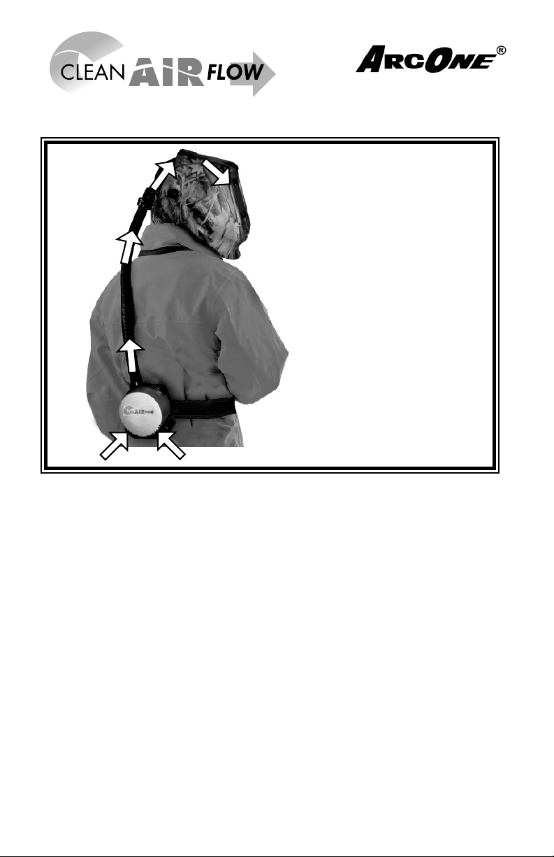
DIAGRAM
A complete Clean Air FlowTM System
Includes:
• A Choice of Lightweight and Durable Nylon Vision or V iper W elding
Helmet or a Hard Hat Visor combination.
• A Choice of Auto-Darkening Welding Lens (welding helmets only)
• Air-O Dynamic Airduct Headgear with Sweatband
• ComfaSeal
• One HE Particulate Filter
• Blower Unit
• 8.4V Lithium-Ion Battery and Charger
• Breathing Tube
• Choice of Adjustable Belts
• Carrying Case (not shown)
TM
Face Seal (Vision helmet only)
Page 5

1.0 General Information
1.1 Introduction
Congratulations! You have purchased the ultimate in comfortable welding
powered respiratory protection equipment manufactured in the world today.
The complete CLEAN AIR FLOWTM Powered Air Purifying Respirator System is
offered in four distinct lightweight headtops: Straight Bill and Reverse Bill Hard
Hat Visor Combo, Vision and Viper welding helmets. The welding helmets include ArcOne’s family of electronic auto-darkening fi lters. (See ArcOne’s Auto-
Darkening Welding Helmets “User Instruction Manual,” for details on ArcOne’s
welding helmets and auto-darkening lenses). The Hard Hats allow faceshield
and welding helmets to be used as accessories on the headtops, opening up
a large range of options (see approval label) to the user.
The Clean Air Flow
TM
Powered Air Purifying Respirator System blows a sup-
ply of fi ltered air over the welder’s face, creating a protective positive pressure
inside the face collar, that keeps out harmful gases, vapors and particulates,
and offers additional comfort when working conditions are hot and humid.
Our goal is to make your demanding job comfortable and safe. The Clean Air
TM
Flow
system is not only engineered for safety and functionality but also for
lightweight comfort. You can wear the Clean Air FlowTM system all day with no
worry of fatigue or respiratory stress.
T o assure your complete satisfaction with the Clean Air Flow
TM
system, we ask
that you read these user and safety instructions thoroughly before using the
system. PLEASE, also take the time to read the Auto-Darkening Welding
Helmets- “User Instruction Manual” (if applicable) which is enclosed.
The complete Clean Air Flow
TOTAL PROTECTION to the user - (1) Clean Air Flow
ERED AIR PURIFYING RESPIRATOR
TM
System has been engineered for:
- Filters the air that a user
TM
POW-
breaths into his or her lungs. (2) ARCONE’S AUTO-DARKENING
LENS - Protects the eyes, and prevents against neck injuries (3) VIPER and VISION SERIES WELDING HELMETS - Ergonomically de-
signed to protect the face, head, and neck areas during welding.
Page 6

1.2 Operating Principals
This Clean Air FlowTM system is used in a welding environment where
protection is required against harmful particles and mist. The Clean
Air Flow
per and Vision welding helmets eliminate much of the wasted motion and
discomfort associated with welding. You will receive a constant fl ow of fresh air,
which will allow you to comfortably remain safely in your work environment for a
longer period of time, and is of particular benefi t where working conditions are
hot or humid.
TM
, in conjunction with ArcOne’s Auto Darkening Lens and Vi-
The Clean Air Flow
TM
blower unit supplies an over capacity of 170 Liters per min-
ute of fi ltered air to the headtop, and allows the user to breathe without having to
overcome the resistance of the fi lter. Considering that an adult person requires
an average of 45 liters of air per minute, the over capacity ensures a slight overpressure and thus a high degree of protection.
The Clean Air Flow
TM
system is powered by a rechargeable Lithium-Ion battery ,
which is encased in durable lightweight plastic. The battery securely attaches to
the blower unit. The battery provides protection for an 8 hour shift. The battery
is delivered in the uncharged state; the charging time for a fully discharged battery
is 8 hours. (See Section 2.1 Battery Charging)
The Clean Air Flow
TM
blower unit should be fi tted with a fi lter appropriate to the
application and selected by a competent person with a full knowledge of respiratory
hazards, and their concentrations that are applicable in the workplace. To ensure
adequate protection, it is essential that the blower unit is correctly confi gured and
that the correct fi lter is used. (See Section 2.2 Filters)
If there is any doubt of final determination of respirator
applicability and fi lter selection, it must be made by an on-site safety
specialist or industrial hygienist. (or contact the National Institute
of Occupational Safety and Health).
Page 7
1.3 Respirator Approvals & Limitations
The Clean Air FlowTM System as described in this instruction manual has been
approved by the following agencies
• NIOSH 42 CFR Part 84 (USA) (See enclosed Appendices)
1. Improper respirator use may cause injury or death. Improper use
may also cause certain life-threatening delayed lung diseases. Regulations require that the employer provide training to the user on proper
use, maintenance and limitations of the Clean Air Flow
2. Each person using these respirators must fi rst read and understand
this entire instruction manual. Before using the Clean Air FlowTM PAPR
system, be sure your employer has determined that airborne contaminant
concentrations do not exceed those allowed by applicable OSHA, MSHA,
EPA, NIOSH or ACGIH regulations for Powered Air Purifying Respirators.
Federal law requires that your employer measure and monitor airborne
contaminant levels in the work area.
3. Failure to use components and replacement parts approved by NIOSH
for use with this respirator system voids NIOSH approval of the entire respirator, invalidates all ARCONE® warranties, and may cause death, lung
disease or exposure to other hazardous or life-threatening conditions.
4. Inspect all components of the Clean Air Flow
TM
cleaning and before and after each use for signs of wear, tear or damage
that might reduce the degree of protection originally provided. Immediately
replace worn or damaged components with ARCONE’S Clean Air FlowTM
PAPR components approved by NIOSH for use with this respiratory system.
5. DO NOT use the Clean Air Flow
TM
PAPR system in inadequately ventilated areas, where oxygen is less than 19.5%, or in confi ned spaces such
as tanks, small rooms, tunnels or vessels unless the confi ned space is
well-ventilated and contaminant concentrations are below the recommendations for this system. The procedures for confi ned space entry, operation
and exit are defi ned in applicable regulations and standards, including 29
CFR 1910.146.
TM
PAPR system.
PAPR system during
Page 8

Cautions and Limitations (refer to the enclosed Approval Labels)
• Not for use in atmospheres containing less that 19.5 percent oxygen.
• Not for use in atmospheres immediately dangerous to life or health.
• Do not exceed maximum use concentrations established by regulatory
standards.
• Do not use powered air-purifying respirators if airfl ow is less than six cfm
(170 lpm).
• Follow established cartridge and canister change schedules or observe
ESLI to ensure that cartridges and canisters are replaced before breakthrough occurs.
• Contains electrical parts which have not been evaluated as an ignition
source in fl ammable or explosive atmospheres by MSHA / NIOSH.
• Failure to properly use and maintain this product could result in injury or
death.
• Follow the User’s Instructions for changing fi lters.
• All approved respirators shall be selected, fi tted, used, and maintained in ac-
cordance with MSHA, OSHA, and other applicable regulations.
• Never substitute, modify, add, or omit parts. Use only exact replacement
parts in the confi guration as specifi ed by the manufacturer.
• Not for use as surgical masks.
This Clean Air Flow
TM
PAPR system is only part of an overall OSHA Respirator
Program, which contains the following documentation:
1. Administration
1. Use of Respirators
2. Selection of Respirators
3. Employee Training, Instructions, and Discipline
4. Inspection, Cleaning, Storage, and Repair
5. Emergency Use Respirators
6. Program Evaluation
Page 9
#1
1.4 Helmet and Auto-Darkening Lens Approvals
The ArcOne helmet, consisting of the Vision and Viper series and the full family
of ArcOne’s Auto-Darkening Lenses have been tested and approved under one
or more of the following Standards Agencies (see specifi c models for standards
that apply):
• ANSI Z87.1 (USA)
• CSA Z94.3-02 (Canada)
• CE - EN 374/EN 175 (Europe)
Limitations (refer to the Auto-Darkening Welding fi lter manual enclosed)
2.0 System Use and Maintenance
2.1 Battery
The Lithium-ion battery included with your system does not need to be manually
discharged.
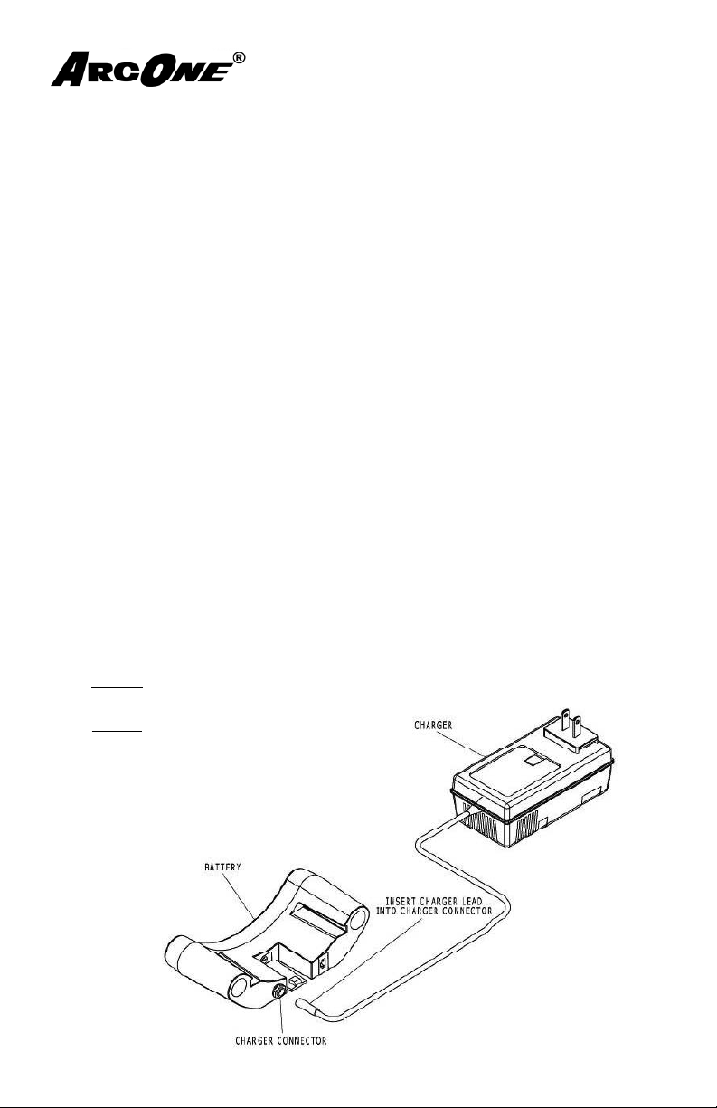
Charge/Recharge Battery:
1. Turn off the Blower if the Battery is connected to the Blower. (Note: the Battery does not need to be disconnected from the blower unit to recharge)
2. Connect the Charger to the Battery (fi g. 1)
3. The Yellow charge LED on the Charger will be lit if charging is necessary.
NOTE: this may take several seconds to indicate.
4. The Green LED on the Charger will be
displayed when battery charging is complete.
Figure 1
Page 10
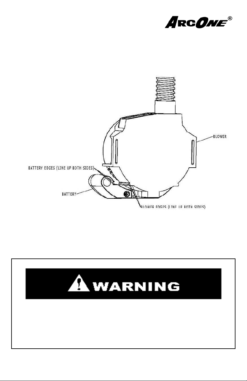
Installation:
#2
1. Line up the edges as shown (fi g. 2).
2. Slide the battery into the Blower.
3. Make sure there is an audible click as the battery is secured to the Blower.
4. Turn on the blower to check battery status (see section 2.3)
Figure 2
2.2 Filters
Read the NIOSH approval labels found enclosed with the fi lter before installing
the fi lter into your Clean Air FlowTM PAPR System.
THIS FILTER IS NOT MEANT TO BE REUSED. DO NOT CLEAN AND
REUSE. HE FILTERS SHOULD NEVER BE USED FOR PROTECTION
AGAINST GASES OR VAPORS. REFER TO SPECIFIC NIOSH FILTER
APPROVAL LABELS FOR SPECIFIC INFORMATION ON USAGE AND
LIMITATIONS.
Page 11
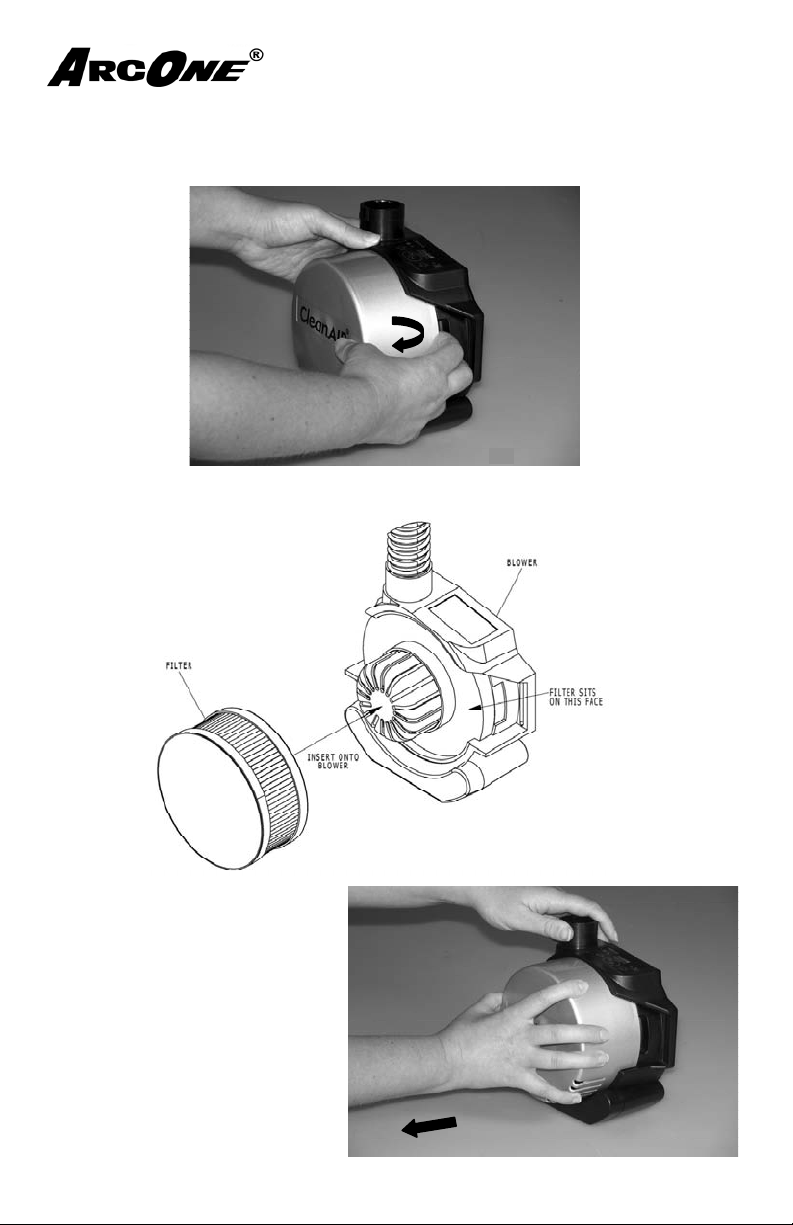
Filter Installation:
Pull tab away
(left & right)
#1
#2
Pull
#3
1. Remove any Filter packaging from the Filter.
2. Remove the Filter Cap from the Blower (fi g. 3).
Figure 3
3. Remove the old fi lter (if installed).
4. Install the Filter onto the Blower (fi g. 4).
5. Install the Filter Cap onto the
Blower, making sure the left and
right tabs snap onto the Blower.
6. Check the Filter Cap is secured
(fi g. 5).
7. Repeat step 5 and 6 if Filter
Cap detaches from the Blower.
Figure 4
Figure 5
Page 12
#1
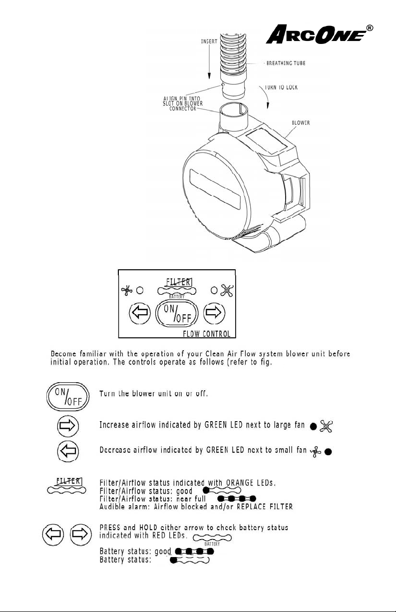
2.3 Blower
#2
1. Install the Breathing Tube
into the Blower as shown (fi g. 6).
2. Operate the Blower (fi g. 7).
Figure 6
Figure 7
7).
Audible Alarm (short beep) & LED’s fl ash RECHARGE BATTERY
fair
Page 13
2.4 Headtop
#1
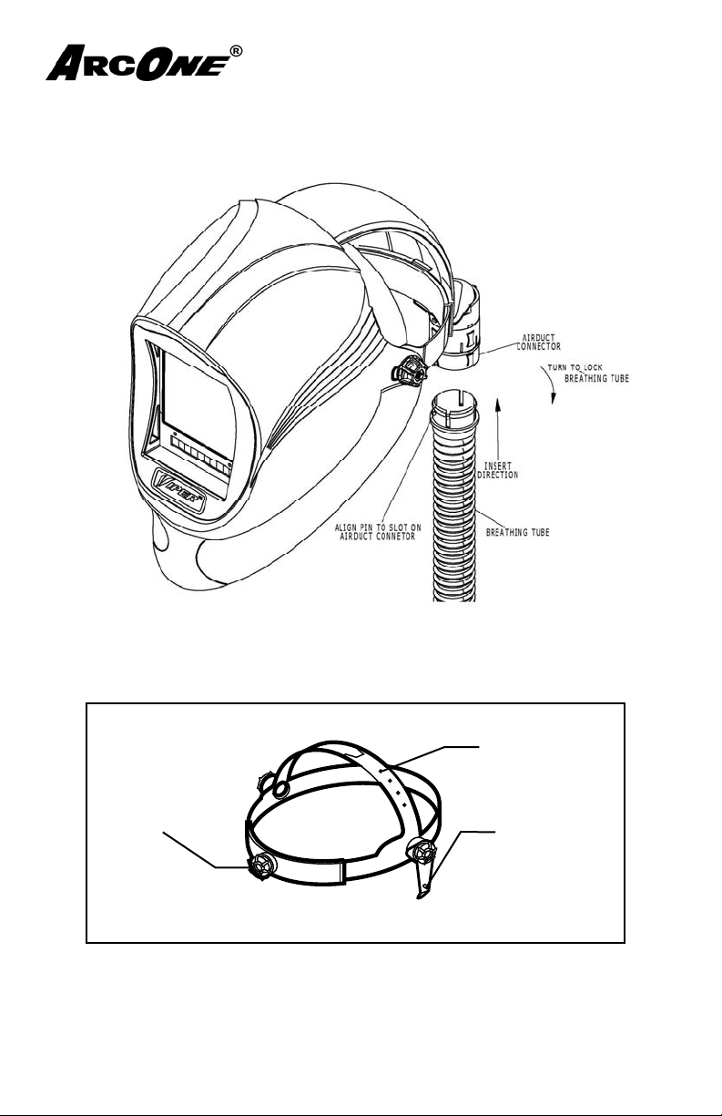
1. Install and Lock the Breathing Tube into the Airduct on the Headtop (fi g. 8)
Figure 8
2. (Welding Helmet headtops only) Adjust the headgear front to back and top to
bottom. NOTE: These adjust ments can be performed after donning. (fi g. 9)
Adjustment Holes
Front To Rear
Adjustment Knob
*
Headgear Shown Without Airduct
Pivot Stop
Figure 9
#2
3. Install the Auto-Darkening Filter, if not already installed (see Auto-Darkening
Welding fi lter manual)
4. Remove spatter label from outside polycarbonate.
Page 14
Hard Hat headtops only:
#3
#4
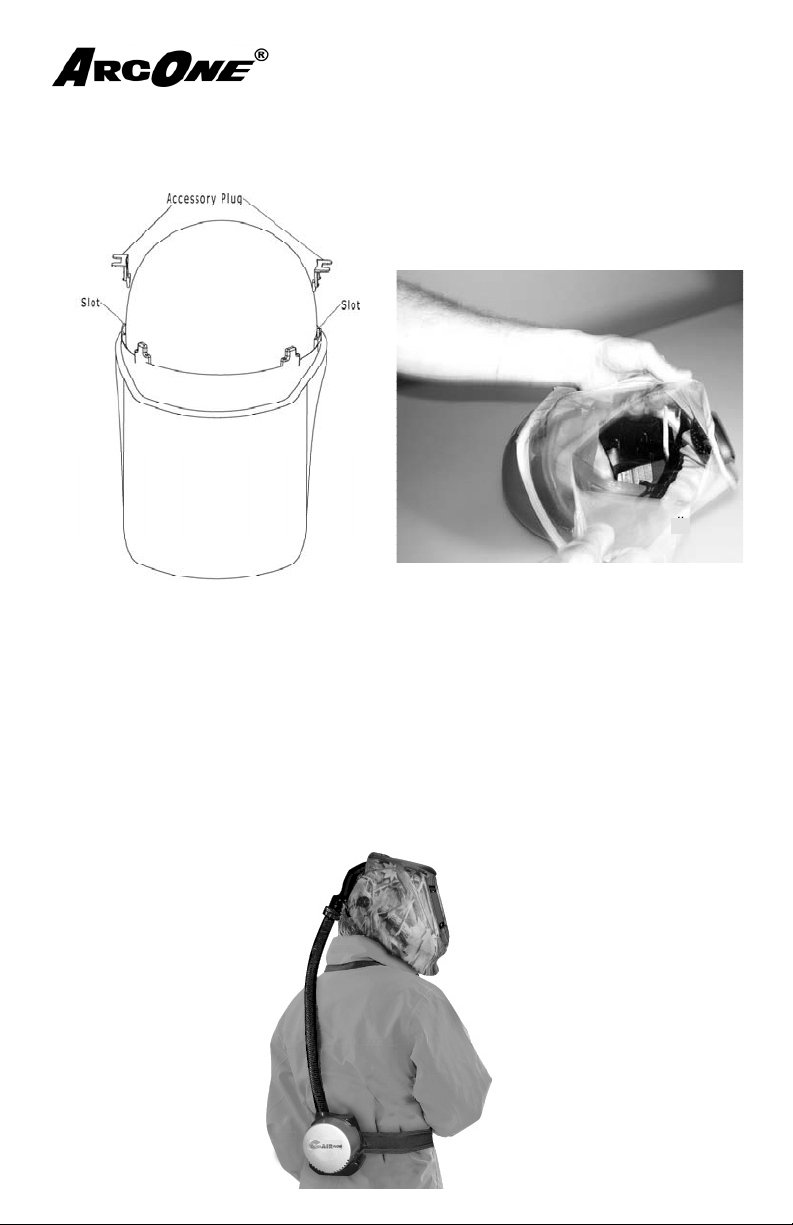
1. Install accessory slot plug (straight bill hard hat only), if not already installed or
optional accessory. (fi g. 9)
2. Remove faceshield visor protective fi lm (fi g. 10):
Figure 10
Figure 9
3. Don the hard hat with visor placed over your face and adjust the headgear to fi t.
4. Adjust the faceseal fi t with the pull cord by pressing on the lock and adjusting
the cord length till a tight fi t is achieved between your face and the faceseal.
2.5 Waist Belt
1. Clip the Waist Belt onto your waist with the blower on your back and the
Breathing Tube pointing upwards (fi g. 1 1).
Figure 11
Page 15

2.6 Pre-Operational Inspection
Check the following before donning your Clean Air FlowTM PAPR system. If any
of the following are not in compliance refer to the section for use and/or maintenance.
TM
1. The space in which the Clean Air Flow
least 19.5% oxygen
2. The space DOES NOT contain explosive gases or vapors.
3. The space is not enclosed in a way that would cause the oxygen level to drop
below 19.5%.
4. The selected Filter meets NIOSH guidelines for the applicable contaminant.
(see NIOSH Pocket Guide to Chemical Hazards available from NIOSH)
5. Battery is installed on the blower unit.
6. Filter is installed in the blower unit and secured with the fi lter cap.
7. Breathing Tube is connected and secured to the Blower unit.
8. Breathing Tube is connected and secured to the Headtop.
9. Faceseal is installed and secured to the headtop.
10. Faceseal is free of holes, runs, and tears.
11. Blower is operational and once turned on check that:
a. The Battery status is above recharge (see section 2.3)
b. The Filter/Airfl ow status is good and the airfl ow is not obstructed (see
section 2.3).
c. Confi rm that there is airfl ow into the headtop.
12. Auto-Darkening Welding fi lter is installed (if applicable) and operational (see
Auto-Darkening Welding fi lter user manual)
Hard Hat headtop only:
13. Faceshield visor is free of holes, rips, and cuts.
14. Faceshield visor protective fi lm is removed. (see section 2.4)
15. Accessory plug or optional accessory is installed. (see section 2.4)
System is to be used contains at
2.7 Donning
Warning: DO NOT Don the Clean Air Flow TM PAPR system before completing the Pre-Operational Inspection (section 2.6).
To Don the Clean Air Flow PAPR system, do the following in the order listed:
1. Perform the Pre-Operational Inspection (section 2.6).
2. Turn on the blower unit and ensure proper airfl ow (section 2.6).
BREATHING MAY BE IMPAIRED IF THE HEADTOP
IS DONNED WITHOUT PROPER AIRFLOW FROM THE BLOWER UNIT.
Page 16
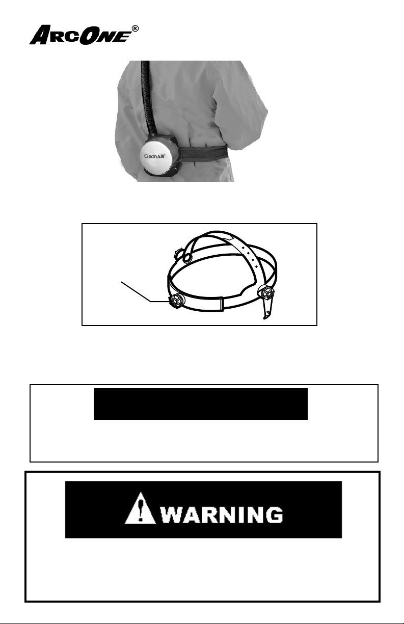
3. Secure the blower unit with waist belt to your body (fi g. 13)
Figure 13
4. Ensure airfl ow into the headtop
5. Don the headtop
6. Adjust the headgear using the front to back adjustment knob (fi g. 14)
Front To Rear
Adjustment Knob
#2
Figure 14
7. Check the height of the headtop and if necessary remove the headtop and
adjust crown height. (see section 2.4)
8. Fit check the faceseal and adjust tightness (if applicable). The faceseal can be
worn in front of or behind the ears.
CAUTION:
Excessive facial hair may cause an incomplete seal. When in doubt
remove excessive facial hair where it interferes with the seal between the
users face and the faceseal.
Failure to properly connect the Breathing Tube to the Helmet
Assembly and to confi rm airfl ow through the system to the
Breathing Zone could lead to contaminant exposure resulting
in serious bodily injury or loss of life.
Page 17
If, at any time during operation, you detect an odor or taste of gas or
Problem Possible Cause(s) Solution
Blower unit off Turn blower unit on
Blocked Breathing Tube
Airduct, or Blower
Remove obstruction
Leak in Airduct or Breathing Tube Replace defective Airduct and/or Breathing Tube
Filter clogged Replace filter
Battery charge low Recharge battery
Battery defective Replace battery
Battery not connected Check battery to blower connection
Battery not installed Install battery
Battery not charged Recharge battery
Defective switch Contact ArcOne customer service
Motor defective Contact ArcOne customer service
Check outlet voltage Connect to good 110 Volt outlet
Defective charger Contact ArcOne customer service
Defective battery Contact ArcOne customer service
Battery fails to charge
Reduced/No Airflow
Blower does not turn on
vapor, or if you feel eye or throat irritation, you must leave the contaminated environment immediately , and refer to the Trouble Shooting
Guide. If necessary , replace fi lter as instructed in Section 4.2. Failure to
refer to the Troubleshooting Guide if the user detects an odor or taste
of gas, vapor, feels eye or throat irritation could lead to contaminant exposure resulting in serious bodily injury or loss of life.
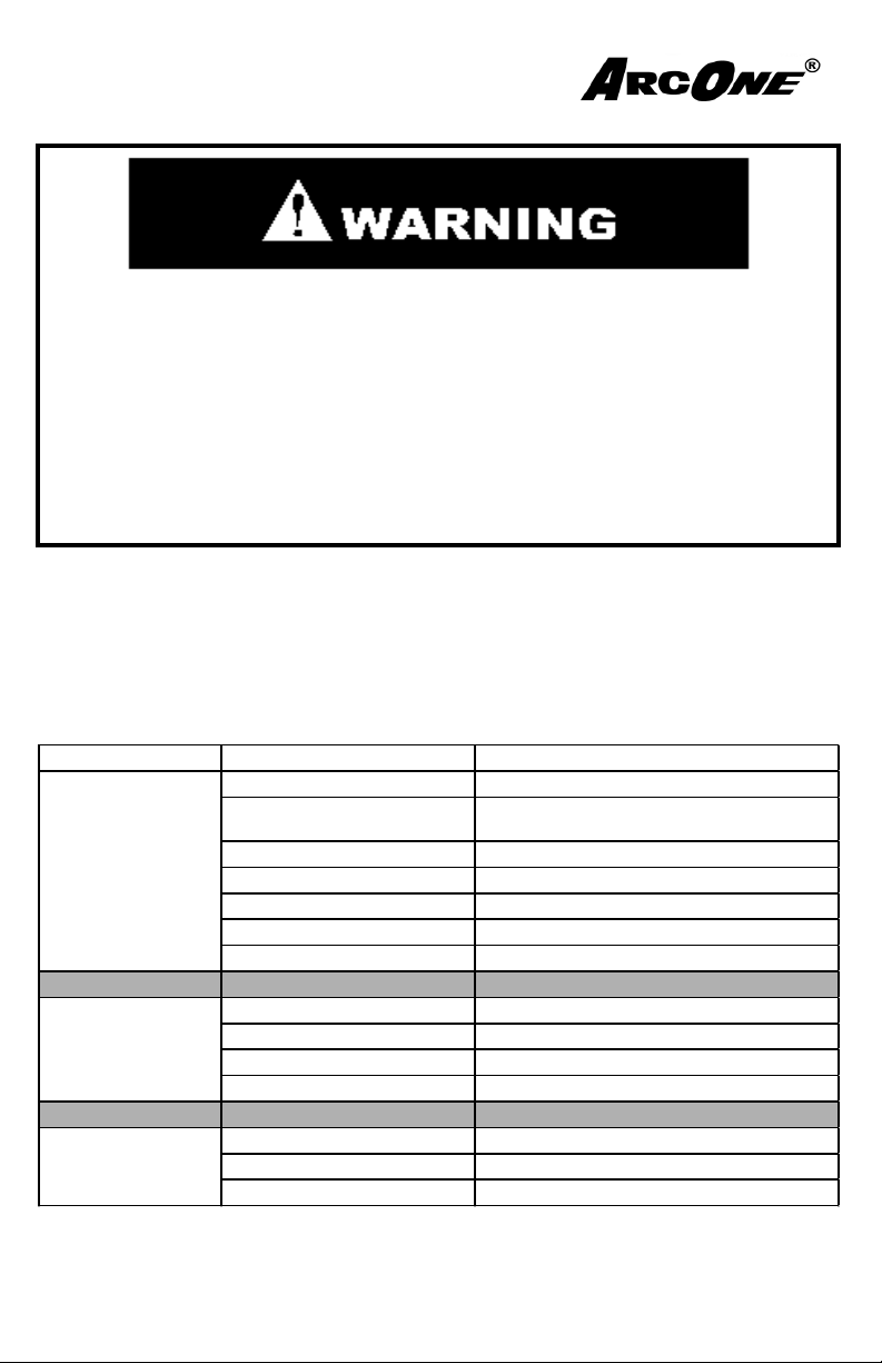
2.8 Troubleshooting
Page 18
3.0 Maintenance and Storage
3.1 Record Keeping
All components should be checked daily when used regularly. Regardless of
usage, each unit requires a documented monthly inspection of all aspects relating to safety . A trained and competent person with full knowledge of respiratory
equipment should carry this out. Records should be maintained throughout the
life of the equipment.
Example of Record
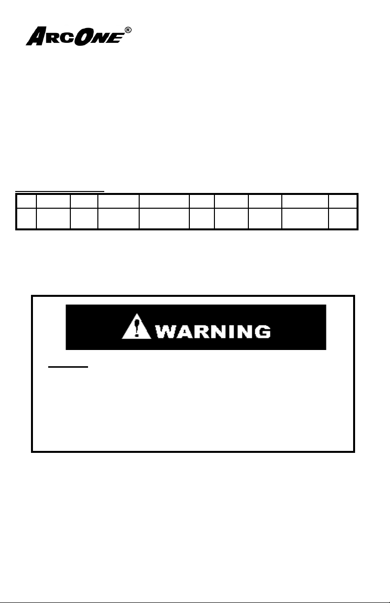
DATE AUTO LENS HELMET FACE COLLAR BREATHING TUBE SEALS FLOW RATE BATTERY BATTERY
CHARGER INITIAL
*THIS IS ONL Y AN EXAMPLE - Regulatory Guidance can be found in the
following documents: OSHA 29 CFR 1910 Part 134 and ANSI Z88.2
Do Not Allow contaminants to enter into the breathing
tube or blower unit. Failure to prevent contaminants from
entering into the breathing tube or turbo unit could lead
to contaminant exposure resulting in serious bodily injury
or loss of life. Consult your local safety professional in
the event contaminant entry in the breathing tube of the
blower unit is suspected.
3.2 Cleaning
1. ALWAYS INSPECT YOUR CLEAN AIR FLOWTM P APR system after
cleaning.
battery pack with a soft cloth dampened in a mild solution of clean water and
mild detergent. Abrasive cleaners should never be used. During cleaning,
ensure that NO water is allowed to enter into the blower unit or battery
pack,this could damage the blower unit’s internal parts. The unit should never
be immersed in any type of liquid.
Clean the external surfaces of the Clean Air FlowTM system and the
Page 19
Cleaning Continued...
2.
Detach the breathing tube from the blower unit and the helmet assembly (see
section 4.3 & 4.4), and wipe the connection sites.
3. Detach the face seal from the helmet assembly before cleaning (see section
4.5). Hand wash in a mild solution of clean water and mild detergent. Allow the
face seal to air dry before attaching it back into the helmet assembly.
4. For helmet maintenance refer to the Auto-Darkening Welding Helmets-
“User Instruction Manual” that is enclosed.
5. For all ArcOne Auto-Darkening lenses refer to the Auto-Darkening Welding
Helmets- “User Instruction Manual” that is enclosed.
6. Let all components dry away from direct heat.
7. Do a thorough inspection (section 3.3) of your Clean Air Flow
tem.
Do not allow water to enter into the blower unit or the battery
pack. Failure to prevent water from entering into the blower
unit or battery pack could cause the product to fail, leading
to contaminant exposure resulting in serious bodily injury
or loss of life. Any fi lter, which has been directly exposed to
water, must be disposed of in accordance with state, local
and federal ordinances.
Do not clean any part of the system with gasoline, organicbased solvents or chlorinated degreasing fl uids (such as
trichloroethylene). Failure to prevent cleaning with any of
these substances could lead to contaminant exposure and/or
product failure resulting in serious injury or loss of life.
TM
PAPR sys-
Page 20
3.3 Inspection
Snap pull
Remove
Direction
#1
1. After cleaning (section 3.2), inspect the individual parts and ensure that all
components and connection sites are clean and in good condition.
2. Inspect for damages; such as, holes, cracks, and scratches on all parts. If in
doubt of effective respiratory performance replace the parts with only ArcOne approved parts for this system.
3. Additionally, inspect the following:
a. Blower unit: Button function. Replace if damaged.
b. Breathing Tube:
o O-ring state. Replace if worn/cut, torn, or if in doubt as to
condition.
o Check for holes or splitting. When in doubt, replace the
Breathing Tube. NEVER patch the Breathing Tube.
c. Faceseal: ensure that the face seal has not lost its elasticity and that
there are no tears or holes. Replace if in doubt as to the condition of
the face seal.
d. Waist belt: ensure the clip securely snaps together.
3.4 Storage
• Before storing the Clean Air Flow
Do Not Keep used fi lter in the same enclosed storage space as new fi lters.
TM
system, it should be thoroughly dry.
• Store the system in a clean area, away from moisture, heat and direct
sunlight. Storage temperatures should not exceed 1200 F.
4.0 Component Replacement
4.1 Battery
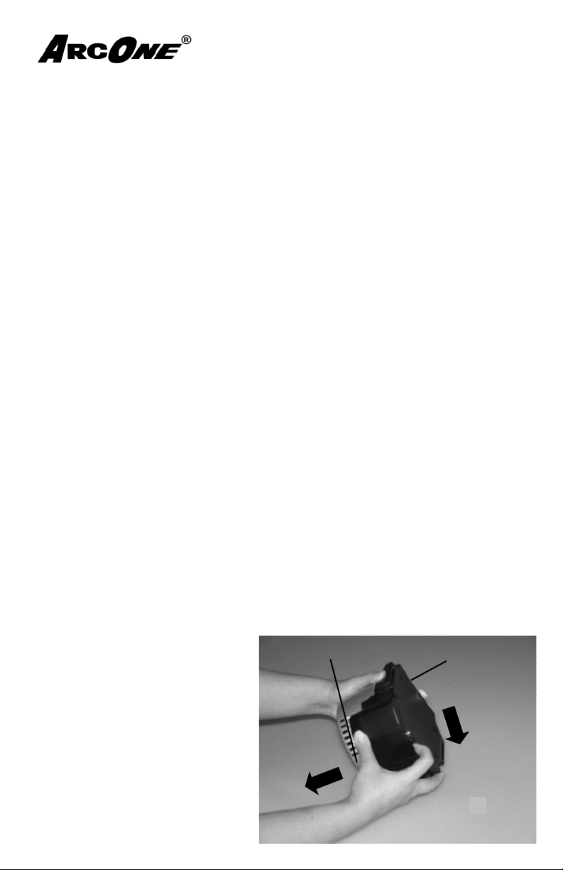
Refer to fi g. 15 for the following steps.
Removal:
1. Pull up on the snap tab.
2. While holding the snap tab away
from the blower pull the battery in
the direction indicated.
Installation: See section 2.1
Battery
Blower
Figure 15
Page 21
4.2 Filter
Removal & Installation: See section 2.2
4.3 Blower Unit Replacement
Note: The blower unit, battery, and battery charger are not user serviceable.
Maintenance or replacement of parts should only be performed by ArcOne, who
has the necessary test equipment to ensure that all repairs are completed safely
and recertifi ed.
The Blower and Battery Units are supplied as seal-tested
units. Any attempt to open or repair the unit will result in
the termination of the limited warranty contained in
Section 5.3
4.4 Breathing Tube
Removal:
1. Turn the Breathing Tube connector counter clockwise and pull out of the
Blower.
2. Turn the Breathing Tube connector counter clockwise and pull out of the Head
top.
Installation: see Section 2.3 & 2.4
4.5 Faceseal
Faceseal Replacement: Viper
Removal:
1. Detach the Airduct from the Headgear.
2. Remove the Airduct from the Faceseal.
3. Remove the Faceseal from the Helmet by pulling the Velcro apart.
Page 22
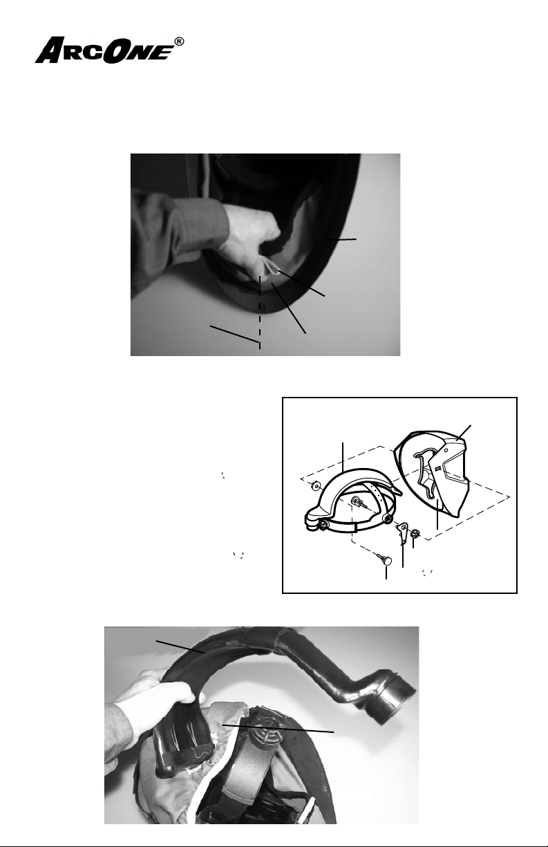
Faceseal Replacement: Viper continued...
Installation:
1. Line up the bottom seam of the Faceseal to the centerline of the Helmet (fi g. 16)
2. Attach the Velcro together along the Faceseal Edge securing the Faceseal to
the Helmet (fi g. 16).
Helmet
Adjustment
Cord
Centerline
Faceseal
Figure 16
3. Attach the headgear to the helmet:
Refer to Figure 17
Step 1-3 refer to Figure 9 insets
1. Place the Pivot Stop inside the Face Seal
on the right side by pushing the pin of the
Pivot Stop into one of the holes on the
helmet.
2. Place the Airduct Headgear Assembly
inside the Face Seal and over the Pivot
Stop boss.
3. Insert the Airduct Headgear Assembly
Bolt through the Airduct Headgear
Assembly lining up all three rectangles
(Bolt, Face Seal, and Welding Helmet
Shell).
4. Screw the Knob onto the Bolt.
5. Repeat on the left side. NOTE: there is no
Pivot Stop on the left side.
Airduct Headgear Assembly
(CA-HGA-01)
Figure 17
Figure 10
Bolt
Pivot Stop
Welding
Helmet Shell
Face Seal (CA-COL-XX)
Knob
4. Insert the Airduct into the hole on the Faceseal as shown (fi g. 18).
Airduct
Faceseal
Figure 18
Page 23
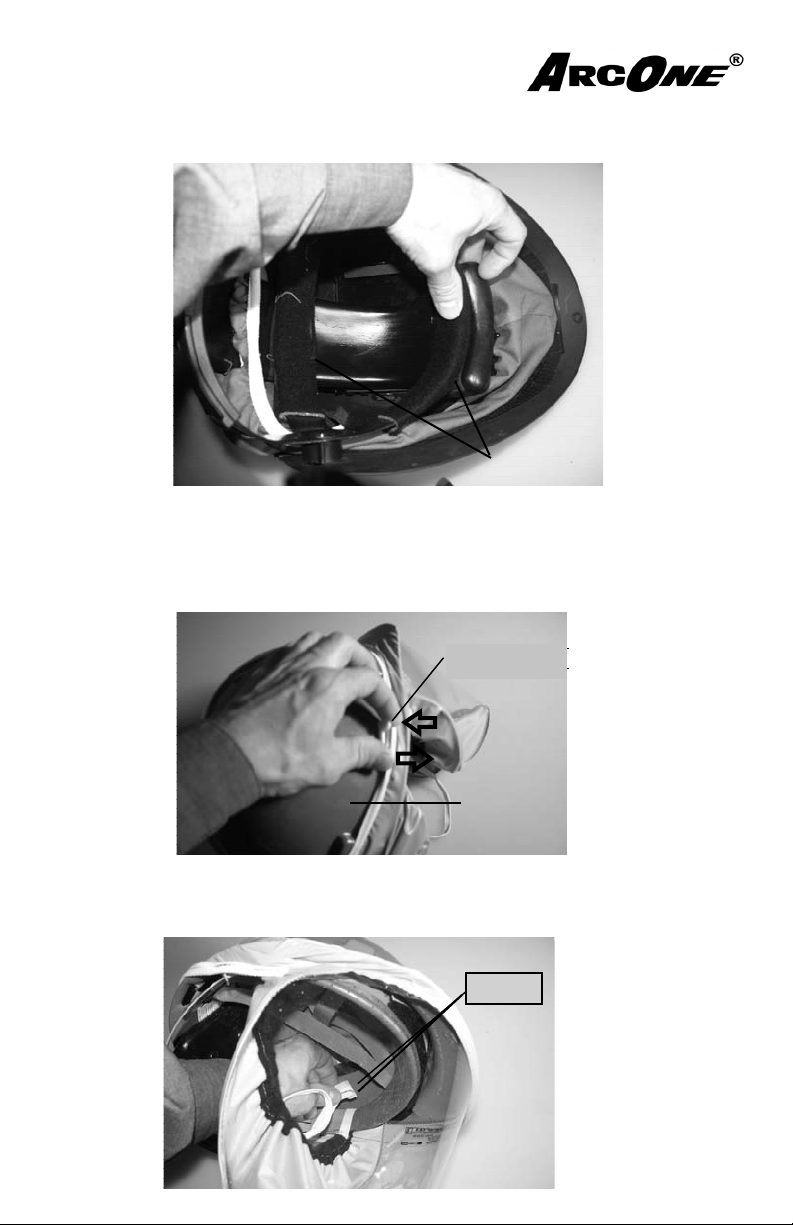
5. Thread the Airduct over the Headgear and attach to the front and top of the
Hard Hat
#1
#2
Headgear with the Velcro strips as shown (fi g. 19).
Figure 19
Velcro
Visor Replacement: Hard Hat
Removal:
1. Remove the accessory or Accessory Plugs from the slots on the Hard Hat (fi g.
20)
Accessory
Plug
Hard Hat
2. Pull the Faceseal from the Airduct and Headgear Ratchet.
3. Detach the Tabs from the Headgear inside the Hard Hat (fi g. 21).
Tabs
Figure 20
Figure 21
Page 24
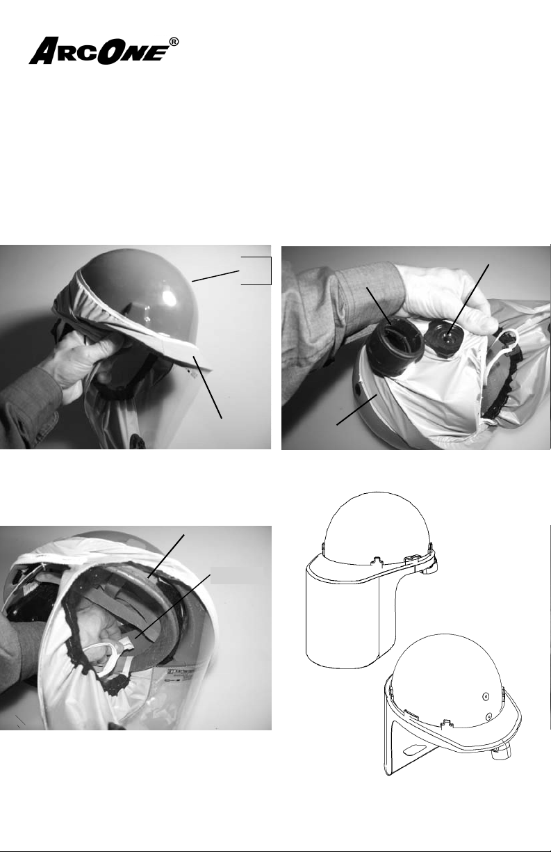
4. Pull the Faceseal off the Hard Hat.
Tabs
#5
Headgear
Hard
Hat
#3
Faceseal
Installation: (Procedure is same for reverse bill hard hat assembly with exception
of faceseal visor orienated on the opposite side of the bill on the hard hat (fi g.
25).
1. Pull the Visor Faceseal over the Hard Hat with the Visor pulled over the Brim
(fi g. 22).
2. Pull the Faceseal over the Airduct and headgear Ratchet (fi g. 23)
3. Attach the Tabs to the Headgear (fi g. 24)
Figure 22
Faceseal
Headgear
Tabs
Hard
Hat
Ratchet
Airduct
Faceseal
Figure 23
Forward
Bill
Reverse
Figure 24
Bill
Figure 25
Page 25
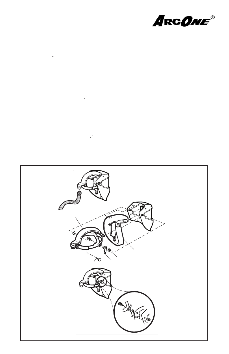
Faceseal Replacement: Vision
p
1. Remove the Face Seal by unscrewing the knob on both sides of the helmet. Be sure to retain
all hardware.
2. Remove Face Seal from shell.
Step 3-5 refer to Figure 8 insets
. 26
3. Install new Face Seal by push pins that are on helmet through holes on Face Seal. Place the
Pivot Stop inside the Face Seal on the right side by pushing the pin of the Pivot Stop into
one of the holes on the helmet.
4. Place the Airduct Headgear Assembly inside the Face Seal and over the Pivot Stop boss.
5. Insert the Airduct Headgear Assembly Bolt through the Airduct Headgear Assembly
lining up all three rectangles (Bolt, Face Seal, and helmet).
6. Screw the Knob onto the Bolt.
7. Repeat on the left side. NOTE: there is no Pivot Stop on the left side.
8. Line up each hole of the Face Seal, one on each side of the helmet and one in the chin area,
in the plastic portion of the Face Seal with the pins installed on the helmet and push the Face
Seal holes into the pins.
NOTE: For the Vision Welding Helmet only-There are (4) four pins installed on the helmet,
two on each side of the helmet.
Welding
Helmet Shell
Airduct Headgear Assembly
(CA-HGA-00)
Face Seal of Corresponding Headtop
(CA-COL-XX)
Knob
Bolt
Pivot Stop
AirDuct Headgear
Assembly
Figure 9
Figure 26
Page 26
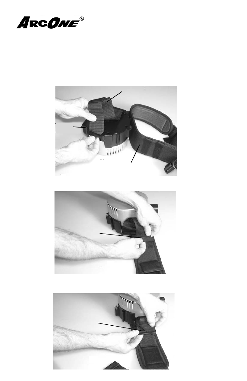
4.6 Waist Belt
#3
Clip
#2
Hoop
#1
Blower
Waist Belt Strap
Waist Belt
Removal:
1. Remove the Waist Belt from the clip.
2. Unthread the Waist Belt Strap from the Blower.
Installation:
1. Thread the Waist Belt Strap through the side slots on the Blower. (fi g. 27)
Waste Belt Strap
Blower
Waste Belt
Figure 27
2. Thread the Waist Belt Strap through the second Hoop (fi g. 28)
Hoop
Figure 28
3. Thread the Waist Belt Strap through the Clip and pull tight to secure the Blower
to the Waist Belt. (fi g. 29)
Clip
Figure 29
Page 27
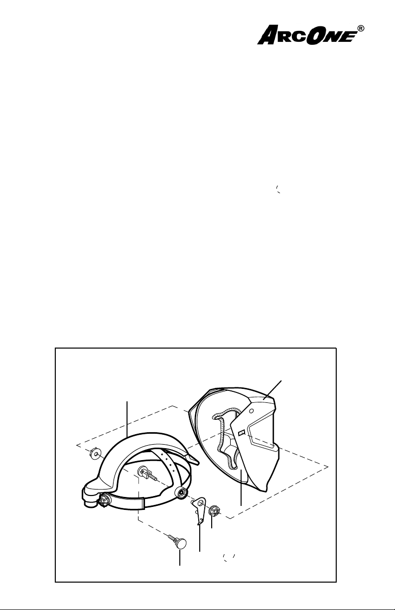
4.7 Airduct Headgear Assembly Replacement
Step 1-3 refer to Figure 9 insets
30
1. Place the Pivot Stop inside the Face Seal
on the right side by pushing the pin of the
Pivot Stop into one of the holes on the
helmet.
2. Place the Airduct Headgear Assembly
inside the Face Seal and over the Pivot
Stop boss.
3. Insert the Airduct Headgear Assembly
Bolt through the Airduct Headgear
Assembly lining up all three rectangles
(Bolt, Face Seal, and Welding Helmet
Shell).
4. Screw the Knob onto the Bolt.
5. Repeat on the left side.
Pivot Stop on the left side.
Airduct Headgear Assembly
(CA-HGA-01)
NOTE: there is no
Welding
Helmet Shell
Figure 30
Face Seal (CA-COL-XX)
Knob
Pivot Stop
Bolt
Page 28

4.8 Auto-Darkening Lens Replacement
Refer to ArcOne’s Auto-Darkening Welding Helmets- “User Instruction
Manual” which is enclosed for information on the following:
• Lens mounting
• Protection plate replacement
5.0 Customer Information
5.1 Replacement Parts and Accessories
When ordering replacement parts or accessories, use the part numbers and
descriptions listed below. Failure to use only CLEAN AIR FLOWTM P APR parts
and accessories will void the NIOSH Approval and ArcOne’s warranty and may
expose the user to the risk of serious bodily injury or loss of life. ArcOne is
not responsible for system performance if components other than CLEAN
AIR FLOW
TM
PAPR parts are used to repair or refurbish the equipment.
Page 29

5.1.1 Replacement Filter Cartridges:
Part No. Description
CF01-P3 HE HEPA Filter Cartridge
5.1.2 Blower Unit System Replacement Parts:
Part No. Description
CF01-BLU-01 Basic Blower Unit
CF01-BAT-01 Lithium Battery
CF-WBT-01 Narrow Waistbelt
CF-WBT-02 Wide Waistbelt
CF-BTC-01 Breathing Tube
CF-BCH-01 Smart Battery Charger
5.1.3 Helmet Assembly:
Part No. Description
CA-HGA-01 Ratchet Headgear - AirDuct Assembly
01-HGA Ratchet Headgear Fastener Assembly & Pivot
Stop
CA-HGS-01 Headgear Sweatband
CF-COL-05 Face Seal, Vision
CF-COL-09 Face Seal, Viper
CF-COL-HV Face Seal with Visor, Hard Hat
CF-COL-HR Reverse Bill Hard Hat Face Seal & Visor
See ArcOne’s User Instruction Manual for Auto-Darkening Lens-
es and Welding Helmets for specifi c replacement parts that are
not covered in this manual.
Page 30

5.2 Technical Specifi cations
Compact Air PAPR System
Blower Unit
Type: Flow Control
Rotor Speed: 6,000-10,000 rpm
Rotor: Brushless
Air Supply (min.) 6 cubic feet (170 liters) per /min
Case: Impact-proof ABS
Belt Plate: Fiber Glass reinforced polyamide
Filter Cartridge: Single plug in type
Hose Length: 29.5 in/750mm
Hose Diameter (int): .87 in/22mm
Hose Connection: Bayonet Connection
Weight: 1.0 lbs. (.48 kg.) L- 6.9” x W-4.2” x H-7.5”
Dimensions: L- 174mm x W-107mm x 191mm
Color: Black/Silver
Battery
Type: Lithium Ion
Voltage: 14.4 Volt
Operating Time: 8 hour shift from fully charged battery
Charging Time: 6 hr. (max.)
Charging Cycles: 500 Times (under ideal conditions)
Housing: Impact-proof ABS
Weight: .6 lbs. (.27kg.)
Dimensions: L- 5.9” x W - 2.9” x H - 1.65”
L- 150mm x W - 74mm x H-42mm
Color: Black
Charger
Type: DC Rectifi er
Primary Voltage 120 V/60Hz
Secondary Voltage: 14.4 VDC
Output Current: 570mA
Weight: .57 lb (.26 kg.)
Dimensions: L- 4.65” x W- 2.4” x H- 2.75”
L- 118mm x W- 62mm x 70mm
Color: Black
Approvals: UL/CSA/CE
Page 31

5.2 Technical Specifi cations Cont.
Welding Helmet
Vision & Viper
Material: Nylon
Heat Resistant, Abrasion & Chemical Resistant
Weight: Less than 1lb.
Style: Vision (5x4, 2x4 & 2x4 lift visual opening) vertical
mount
Viper (5x4) vertical mount
Colors: Black, Red, Cool Refl ective Silver, Decaled
Hard Hat with Visor
Material (Hard Hat): Nylon (glass fi lled)
Weight: 1.14 lb.
Colors: Red, White, Blue, Yellow, Decaled
Auto-Darkening Lens
Types: Single Shade, Variable Shade
Manual Adjust, Automatic Adjust
Sizes: 51/4” x 41/2” x 1/7” Vertical
2” x 41/4” x 1/7”
Shade: UV/IR Protection to Shade 16
Switching Time: .5 mil seconds or less
Power: Solar Cell-or battery
Approvals: ANSI Z87.1 - American National Standard for
Eye & Face Protection
CSA Z94.3 - National Standard of Canada for
Industrial Eye and Face Protection
(Specifi c models only)
CE EN379 - European Standard for Auto-Darkening
Filters
See ArcOne’s User Instruction Manual for Auto Darkening Helmets
for Helmet and Lens Replacement Parts which is enclosed.
Note: NIOSH Approval covers complete respirator systems only,
as confi gured from approved components as referenced on the
NIOSH approval label for this system(s).
Page 32

5.3 Warranty
ArcOne warrants the complete Clean Air FlowTM P APR Systems for one (1)
year from the date of purchase against all manufacturing defects resulting from
materials or workmanship. Proof of purchase establishing the sale date of
the respiratory system must be provided, should a warranty claim be submitted. The purchaser’s only remedy under this limited warranty shall be
limited to ArcOne’s sole option to repair, replace or refund (not to exceed
the purchase price). This limited warranty is void in the case of unauthorized modifi cation, tampering, and damage due to misuse, abuse, inadequate
maintenance or improper storage. This limited warranty is not transferable
from the original purchaser to a secondary owner. ArcOne shall in no event
be liable or responsible from the use or misuse of this product. This limited
warranty is exclusive and is in lieu of any other warranty implied, either oral
or written. Please read the instruction manual carefully to avoid certain situations which may void this limited warranty.
5. 4 Warranty Registration Card
ArcOne provides you with a W arranty Registration Card, which should be fi lled
out as soon as you unpack the product. Please note that the warranty card is for
the complete system which includes the Clean Air Flow
welding helmet and auto-darkening lens.
TM
P APR and attached
Page 33

5.5 Customer Service
Should you have any questions concerning the use or performance of the
Clean Air FlowTM P APR System; please contact our Customer Service Department
during normal business hours (8:00 A.M. to 5:00 P.M. EST) at 1-800-223-4685.
Our Customer Service representatives are always available to assist you.
4.6 Servicing Your Clean Air Flow
TM
PAPR System
Please contact ArcOne directly for any questions regarding the function of your
Clean Air Flow
• All Warranty repairs are covered by warranty for the balance of the orginal
warranty period.
• All Non-Warranty repairs carry a 90-Day, limited warranty.
Do Not return your ArcOne Clean Air Flow
TM
PAPR System.
TM
PAPR System to your Distributor.
Call
ArcOne Service Center
(800-223-4685)
MONDAY - FRIDAY
8:00 A.M. - 5:00 P.M. E.S.T.
Or
Visit Our Website
www.arc1weldsafe.
Page 34

Please Contact: ARCONE Service Center,
NOTES:
Telephone: 800-223-4685, Fax: 508-884-9666
Or
Visit Our Website
www.arc1weldsafe.com
A Division of A. C. E. International Company, Incorporated
85 Independence Drive, Myles Standish Industrial Park, Taunton, MA 02780
Tel: 508-884-9600 Fax: 508-884-9666 800-ACE-INTL (223-4685)
Page 35

Please Contact: ARCONE Service Center,
NOTES:
Telephone: 800-223-4685, Fax: 508-884-9666
Or
Visit Our Website
www.arc1weldsafe.com
A Division of A. C. E. International Company, Incorporated
85 Independence Drive, Myles Standish Industrial Park, Taunton, MA 02780
Tel: 508-884-9600 Fax: 508-884-9666 800-ACE-INTL (223-4685)
Page 36

Please Contact: ARCONE Service Center,
Telephone: 800-223-4685, Fax: 508-884-9666
Or
Visit Our Website
www.arc1weldsafe.com
A Division of A. C. E. International Company, Incorporated
85 Independence Drive, Myles Standish Industrial Park, Taunton, MA 02780
Tel: 508-884-9600 Fax: 508-884-9666 800-ACE-INTL (223-4685)
 Loading...