

Page 1

-.y'*¥*'■«
áy
û
ARCAM
Alpha I О/1 OP Amplifier
Page 2
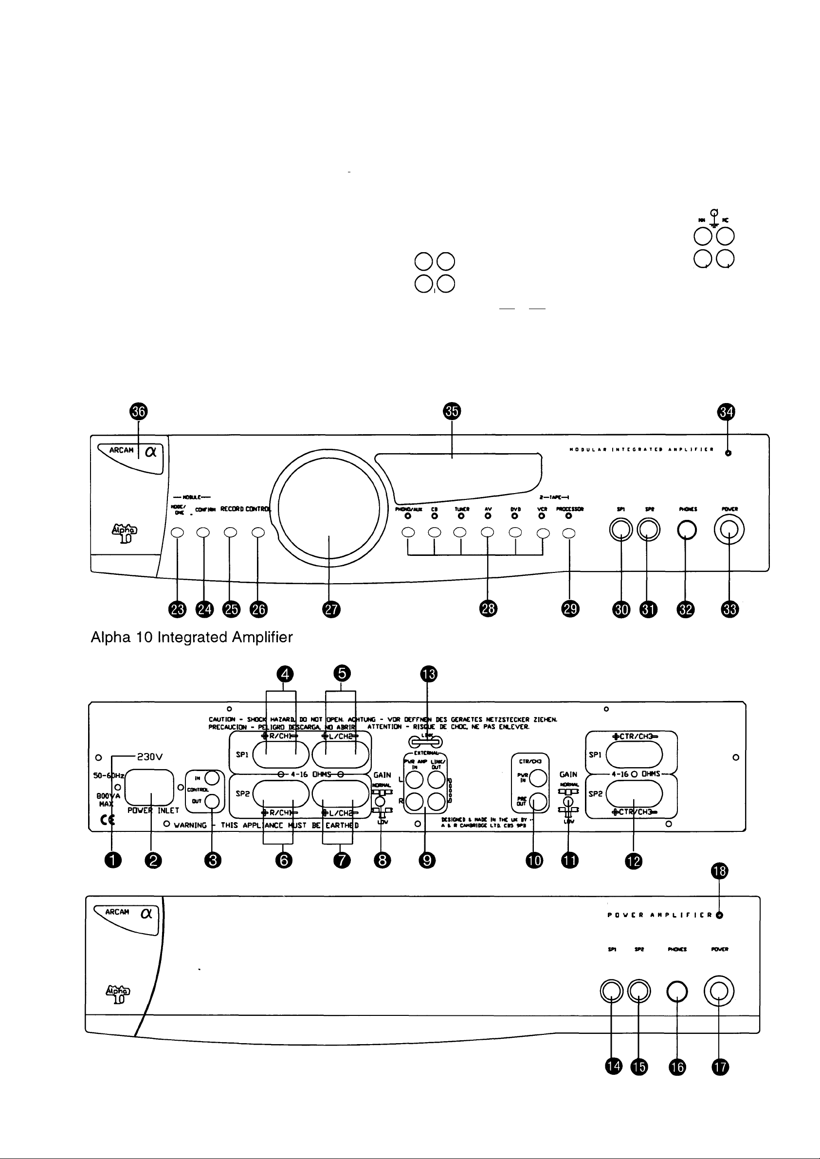
Front & Rear Panel Diagrams
O
I
800' 'A
HA9
cc
acMM - «■ (cmn Ki oBMC>c< «Cl rncea« r
«iitMH« • mM ic CMC ac iHf o.
-P'inV APPLIANCE
POWEl! INLET
WARNING
MUST BE EARTK I
f
_________________
SPl
C
>
------------------
tm vMMt m m i ir «« ra Ib n.
;h_R_::_______> L ■ JqF
)C
0-4-16 QHMS-e
--------------
)
< GAIN
QPP OTOPTOTOTO
oooooooo
acM P AY
0 IT I w
p ocyiAA: i>V V at/TAPc
aci o«D ^ AT
0 IT II
M I 0» 1«
SVITC «B IN1 CMALLY
Ksw :t ft MMC I
FTIOK
lq
R
Alpha 10P Power Amplifier
Page 3

Safety Instructions - Please read before operating the equipment ENGLISH
SAFETY INSTRUCTIONS
This product was designed and manufactured to meet strict
quality and safety standards. There are, however, some
installation and operation precautions which you should be
particularly aware of:
1. Read Instructions - All the safety and operating
instructions should be read before the appliance is
operated.
2. Retain Instructions - The safety and operating
instructions should be retained for future reference.
3. Heed Warnings - All warnings on the appliance and in
the operating instructions should be adhered to.
4. Follow Instructions - All operating and use instructions
should be followed.
5. Water and Moisture - The appliance should not be used
near water - for example near a bathtub, washbowl,
kitchen sink, laundry tub, in a wet basement or near a
swimming pool, etc.
6. Carts and Stands - The appliance should be used only
with a cart or stand that is recommended by the
manufacturer.
6A. An appliance and cart combination should be moved with
care. Quick stops, excessive force, and uneven surfaces
may cause the appliance and cart combination to
overturn.
7. Wall or Ceiling Mounting - The appliance should be
mounted to a wall or ceiling only as recommended by the
manufacturer.
12. Power-Cord Protection - Power supply cords should be
routed so that they are not likely to be walked on or
pinched by items placed upon or against them, paying
particular attention to cords and plugs, convenience
receptacles and the point where they exit from the
appliance.
13. Cleaning - Unplug the unit from the mains supply before
cleaning. The appliance should normally only require a
wipe over with a clean, dry, lint-free cloth. If it is heavily
soiindicator then a cloth slightly dampened with a
water/washing up liquid solution may be used. Dry the unit
afterwards with a dry cloth. We do not advise the use of
furniture type cleaning sprays/polishes as this can cause
white marks, which are very difficult to remove, if the unit
is then wiped over with water.
14. Power Lines - An outdoor antenna/ aerial should be
located away from power lines.
15. Non-use Periods - The power cord of the appliance
should be unplugged from the outlet when left unused for
a long period of time.
16. Object and Liquid Entry - Care should be taken so that
objects do not fall and liquids are not spilindicator into the
enclosure through any openings.
17. Abnormal Smell - If an abnormal smell or smoke is
detected from the appliance, immediately turn the power
off and unplug the unit from the wall outlet. Contact your
dealer immediately.
18. Damage Requiring Service - The appliance should be
serviced by qualified service personnel when:
8. Ventilation - The appliance should be situated so that its
location or position does not interfere with its proper
ventilation. For example, the appliance should not be
situated on a bed, sofa, rug or similar surface that may
block the ventilation openings or placed in a built-in
installation, such as a bookcase or cabinet that may
impede the flow of air through the ventilation openings.
9. Heat - The appliance should be situated away from heat
sources such as radiators, heat registers, stoves or other
appliances (including amplifiers) that produce heat.
10. Power Sources - The appliance should be connected to
a power supply only of the type described in the operating
instructions or as marked on the appliance.
11. Grounding - Precautions should be taken so that the
grounding means of the appliance is not defeated.
A. The power-supply cord or the plug has been damaged or:
B. Objects have fallen, or liquid has spilindicator into the
appliance or:
C. The appliance has been exposed to rain or:
D. The appliance does not appear to operate normally or
exhibits a marked change in performance or:
E. The appliance has been dropped or the enclosure
damaged.
19. Servicing - The user should not attempt to service the
appliance beyond that described in the operating
instructions.
All other servicing should be referred to qualified service
personnel.
Page 4

Introduction & Installation
ENGLISH
INTRODUCTION
This manual is in four sections;
A. Information relevant to both the Alpha 10 and Alpha
10P.
B. Alpha 10 integrated amplifier operating instructions.
C. Alpha 10P power amplifier operating instructions.
D. Instructions on how to bi-wire or to bi-amplify (“bi-amp”)
your loudspeakers.
Circindicator numbers e.g. refer to items on the
diagrams inside the flap of the front cover.
Section A
INSTALLATION
O Check that your mains supply voltage agrees with the
voltage setting indicated on the rear panel of the unit.
■ If your mains supply voltage is different, consult your
Arcam dealer.
NOTES ON USE
The Alpha 10 and 10P amplifiers will play music within seconds
of being switched on. However the optimum sound
reproduction will be achieved after the units have been
powered up for a few minutes.
Note: On switch on there may be an audible hum from the
transformers within the units. This is normal and should
disappear within a few seconds.
CAUTION: Your Alpha 10 and Alpha 10P generate heat when
in use, particularly at higher volumes. It is therefore most
important never to obstruct the ventilation slots on the top and
bottom of the unit as this will cause overheating.
If the temperature of the internal heatsinks rises above a safe
level, then a thermal cut out inside the amplifier will operate.
The POWER INDICATOR on the front panel will turn amber
and the output protection relays will temporarily remove the
feed to the loudspeakers. The system will reset itself as the
heatsinks cool down.
Please note that under certain conditions it may be possible for
the Alpha 10 or Alpha lOP's thermal cut out to operate when
playing music at very high levels.
MAINS SAFETY
■ This product is normally supplied with a moulded mains
plug already fitted to the lead. If for any reason the plug
needs to be removed, it must be disposed of
immediately and securely, as it is a potential shock
hazard when inserted into a mains socket.
■ Warning: This apparatus must be earthed.
NOTICE FOR U.K. OWNERS ONLY
■ If the plug is removed then the remaining lead must be
rewired as follows:
■ The blue wire must be connected to the terminal which
is coloured blue or marked with the letter N.
■ The brown wire must be connected to the terminal
which is coloured brown or marked with the letter L.
i The green and yellow wire must be connected to the
terminal which is coloured green and yellow, or marked
with the letter E or the safety earth symbol.
■ When replacing the fuse in the supplied moulded mains
plug, the integral fuse holder/cover must always be
refitted. Use a 5 amp fuse.
SAFETY STANDARD
This might for example happen when continuously playing
heavily compressed rock music "flat out" into low impedance
(4-6 ohm) speakers. If this happens to you, the cure is to turn
the volume down slightly and ensure the amplifier is properly
ventilated.
It is important to point out that when playing a heavily recorded
CD it is possible to drive the Alpha 10 at full power despite the
fact that the volume is not at maximum. This is because of the
high output voltage from a CD player. However the Alpha 10
also has to be capable of giving full power output from much
lower level sources, such as tuners and cassette decks. Using
these sources, the volume setting will be much higher before
overload sets in.
Section B
ALPHA 10 INTEGRATED AMPLIFIER
Please refer to drawing inside front cover.
LOUDSPEAKER CONNECTIONS
■ The amplifier is fitted with BFA (British Federation of
Audio) loudspeaker connectors, which are designed to
meet EU safety standards.
The BFA connector will accept spade terminals, bare
wires or a BFA plug. BFA plugs are available from your
Arcam dealer.
■ This product has been designed to meet the I EC 65
international electrical safety standard.
MAINS SUPPLY CONNECTIONS
Insert the lEC line socket of the mains lead fully into the O0
power inlet on the rear panel. Connect the other end to
your mains supply.
The speaker terminals are colour coded red for positive
and black for negative. These terminals are also
labelled 'R' for the right channel speakers and 'L' for the
left channel speakers.
Connect terminals © to your right speaker and
terminals 0 to your left speaker, ensuring correct
polarity.
Page 5

ENGLISH
Connect the red cable termination to the red terminal
and the other cable termination to the black terminal. If
your speaker cable has bare ends, the positive
conductor can usually be identified by a ridge or
coloured marking.
Ensure that no stray strands are allowed to touch
another cable or the amplifier's casing. This can cause
a short circuit and damage your amplifier!
®o
CONNECTING YOUR SOURCE COMPONENTS
0^
To drive a second pair of speakers, connect terminals
® to the right speaker and terminals O to the left
speaker, ensuring correct polarity.
The Alpha 10 can drive two pairs of loudspeakers,
simultaneously if required, providing both pairs are rated
between 8 and 16 ohms. Either pair can be selected
using the switches labelled SP1 and SP2 on the front
panel. To avoid overheating, the combined load
impedance as seen by the amplifier should not fall below
4 ohms per channel.
■ Using a suitable pair of interconnect cables, insert the
red phono plugs into the sockets labelled 'R' and the
other phono plugs into the sockets labelled 'L'.
All the line inputs (not PHONO) have the same
sensitivity and may be used with equipment other than
that labelled, if you need to do so.
PROCESSOR/TAPE 1 RECORD OUT - Connect this
output to the input sockets of your tape deck (RECORD)
or the tape or line input sockets of your AV processor.
PROCESSOR/TAPE 1 PLAY IN - Connect this input to
the output sockets of your tape deck (PLAY) or the tape
or line output sockets of your AV processor.
VCR/TAPE 2 RECORD OUT - Connect this output to
the input sockets of your tape deck (RECORD).
This module is compatible with most high output moving
coil and moving magnet cartridges (MM) and low output
moving coil cartridges (MC).
MM or MC is selected via an internal switch. Your
cartridge type should be specified when the module is
fitted.
0
OPERATION OF THE ALPHA 10 INTEGRATED AMPLIFIER
©
©
MM - For connecting a turntable fitted with a high output
moving coil or a moving magnet (MM) cartridge.
MC - For connecting a turntable fitted with a low output
moving coil (MC) cartridge.
GROUND TERMINAL - For connecting your turntable's
earth lead (if fitted).
REMOTE CONNECTION - These connections are for
use in multi-room installations. In normal use there is no
need to make any connections to these sockets. If you
are biamping with an Alpha 10P see section Alpha
10/1 OP Remote Switching for details of how to power
both units on/off simultaneously.
GAIN - This switch allows you to change the sensitivity
of the amplifier to match the gain when biamping to
external power amp. The normal position is suitable for
use when biamping with Arcam power amplifiers such as
the Alpha 9P or 10P. The low gain position is suitable
for certain specialist home theatre systems.
BLANKING PLATE FOR OPTIONAL FUTURE
MODULES.
MODE/ZONE - «^CONFIRM - These buttons are only
for use with optional modules. They have no function on
their own in normal use of the basic Alpha 10 although
MODE/ZONE
(see
0
).
0
can be used to select processor mode
VCR/TAPE 2 PLAY IN - Connect this input to the output
sockets of your tape deck (PLAY).
DVD - Connect this input to the audio outputs of a DVD
player.
0
0
A/V - Connect this input to the audio outputs of an
Audio-Visual product such as a VCR, Laserdisc player
or Nicam tuner.
TUNER - Connect this input to the audio outputs of your
radio tuner.
CD - Connect this input to the audio outputs of your CD
player or DAC (digital to analogue convertor).
AUX - Connect this input to the audio outputs of any
unit with a line level output, eg. tape deck, tuner etc.
Please note: The AUX inputs must not be used if the
phono module is fitted. When the phono module is fitted
AUX becomes an output carrying the equalised phono
signal at line level.
PHONO OPTION - Please note: The phono inputs are
on a separate plug-in module which your Arcam dealer
or distributor can supply and fit.
RECORD SELECTOR - This allows you to change the
input that you wish to record from, from that selected by
the INPUT SELECTORS. Alternatively this switch can
also be used as a simple ‘second zone’ selector, routing
a chosen source signal at line level to a second amplifier
operating in another room in the house. The default
setting is the input you are currently listening to
("SOURCE"). To select a different input to record from
first press RECORD. The display will first show
“RECORD SOURCE”. To change the record input press
the desired input button within a few seconds.
The display will indicate the selected recording option for
a few seconds and then revert back to showing the
volume bar graph.
The selected input will be sent to both the VCR/TAPE 2
and PROCESSOR/TAPE 1 record out sockets, unless
you are using the TAPE 1 sockets in processor mode
where it is sent to VCR/TAPE 2 only.
CONTROL - This button cycles through the functions
that can be controlled by the rotary control 0. This can
be either volume (the default setting) or balance, unless
an optional module is fitted, in which case the options
are determined by that module.
Page 6

ENGLISH
In volume mode the display shows bargraph indication
of the volume setting. It will take about 2 or 3 full
revolutions of the volume knob to go from zero to full
output. In balance mode the rotary control allows you to
vary one channel relative to the other. It is not possible
to use the balance control to mute one channel
completely.
VOLUME/BALANCE - Adjusts the volume level of the
loudspeakers, preamp out and headphones. It can also
be used in conjunction with the control button as a
balance control (see ©).
The VOLUME setting can be controlled with the supplied
remote control handset. Note that the control is not
motorized so the knob will not move when adjusted
remotely. If you operate the control too quickly it will not
respond. This is to prevent accidentally setting the
volume too Ngh.
INPUT SELECTORS - Selects the input you wish to
listen to. The selected signal also goes to both the VCR
and PROCESSOR RECORD output sockets unless you
have chosen to record from a different input to the one
you are listening to (section ©). The inputs can also be
selected by remote control.
PROCESSOR/TAPE 1 - This is tape loop to permit you
to monitor a recording made on a 3 head cassette deck.
It can also be used to connect to an external surround
decoder such as the Arcam Xeta 2. Selecting this input
overrides the other input selectors ®.
To play back or to monitor the recording from a cassette
deck attached to the PROCESSOR/TAPE 1 input press
the processor button 'TAPE' is shown on the
display.
For use with an external processor the Alpha 10 can be
put in to processor mode by first selecting PROC and
then whilst holding in the MODE button ® press the
PROC button ® again. The display will now show
"PRO" in place of "TAPE". If the processor you are
using is an Arcam Xeta 2 then press the PROC button
again while holding in the MODE button so that “PR02"
is displayed.
The volume level of the Alpha 10 will now be fixed so
that you can use the volume control of the external
processor as a master volume control. Using the
volume or mute buttons on the remote handset or the
front panel control knob will have no effect whilst in
processor mode. The unit will return to processor mode
whenever ® is pressed.
Once in "PR02" mode the AV, TAPE 1, VCR and DVD
buttons on the CR35 remote control will have no effect.
This is because the Xeta 2 will also respond to these
remote control codes and switch to the wrong input.
If you want to change the input back for use as a normal
tape input hold the MODE button in and press the
PROCESSOR button until 'TAPE' appears on the
display.
CAUTION: Do not set the Alpha 10 to processor mode
if you have a cassette deck or other line level source
attached to the PROCESSOR/TAPE 1 input. This is
because selecting processor mode input will send a
fixed volume signal straight into the power amplifier
which could damage your loudspeakers.
® SP1 - Selects or defeats the main pair of speakers.
Push the button in to select.
SP2 - Selects or defeats the secondary pair of speakers.
Push the button in to select.
Important note: If both switches are turned off then the
amplifier will appear not to be functioning, as all
speakers will be switched off!
HEADPHONES SOCKET - Accepts headphones rated
between 8 ohms and 2k ohms fitted with a 6.3mm stereo
jack plug. If you wish to listen on headphones only, use
SP1 and SP2 (if necessary) to mute the speakers. The
headphone socket is always active.
POWER - Switches the unit on and off. The unit can
also be switched into standby by use of the remote
control handset.
POWER INDICATOR - This will initially glow amber.
After a few seconds, it will glow green. When the
indicator glows amber, the speakers are disconnected
and an internal protection circuit is activated. The power
indicator will turn red if the unit has been put into
standby mode by use of the remote control. Under
certain conditions the power indicator may flash and a
fault condition will be shown on the display If this
happens you should unplug the mains lead of the unit
and leave the unit for a few minutes before
reconnecting. If the fault condition persists unplug and
contact your Arcam dealer.
DISPLAY - The display is a multi function type which can
show information about the current operating
parameters of the Alpha 10, such as volume setting,
record input, etc.
REMOTE RECEIVER - The remote receiver is behind
the badge in the top left hand corner of the unit. Ensure
the remote receiver is not obscured or commands from
the remote control handset will not be received.
TAPE RECORDING
■ Note: The Alpha 10 must be fully powered up in order to
record.
■ Both sets of tape sockets are identical in sensitivity and
suitable for use with almost any type of recorder
(cassette, hi-fi VCR, reel to reel, DAT, etc.)
■ Use the RECORD selector to route the required signal
to a cassette deck connected to the TAPE 1 and TAPE
2 RECORD OUT sockets (see section ®).
■ TAPE TO TAPE DUBBING: The Alpha 10 allows two
way tape dubbing (copying) from TAPE 2 to TAPE 1 but
NOT TAPE 1 to TAPE 2. For example, to copy from a
cassette recorder connected to the VCR/TAPE 2
sockets to a cassette recorder connected to TAPE 1,
first use the RECORD selector on the Alpha 10 to select
“RECORD ;VCR" (see section ®). This routes the
TAPE 2 signal to TAPE 1's output. Then set the tape
recorder connected to TAPE ONE sockets into its
'record' mode and the other to 'playback' mode to enable
the transfer to take place. If you wish to monitor the
transfer while it is taking place^select TAPE using the
TAPE 1/PROCESSOR button
Page 7

ENGLISH
® PRE/POWER CONNECTIONS
PWR AMP IN - To use your Alpha 10 just as a power
amplifier, connect the output of your pre-amplifier to the
PWR AMP IN sockets. The Alpha 10‘s internal selector
switch must be changed to disconnect the preamp
stages of the unit. Contact your dealer or Arcam for
more details.
Under these circumstances it has exactly the same
specification and performance as an Alpha 10P power
amplifier.
PREAMP OUT - To use your Alpha 10 as a pre
amplifier, connect the PREAMP OUT sockets to the
input sockets of your power amplifier. With a power
amplifier of the correct gain (e.g. An Arcam Alpha 9P or
10P) this allows you to bi-amplify (“bi-amp”) suitable
loudspeakers, giving significant improvements in sound
quality (see section on BI-WIRING/ BI-AMPING).
REMOTE CONTROL FUNCTIONS
■ Your Alpha 10 amplifier is supplied with the Arcam CR35
infra-red remote control handset, which has buttons to
allow the simple operation of other products. It is
supplied with 2 AA batteries - ensure these are inserted
correctly.
■ The remote allows you to operate the Alpha 10 plus
some basic functions of an Arcam or Philips based CD
player (except the Alpha One CD player, which uses a
different remote control language), a remote controlled
tuner (such as the Alpha 8 tuner) and the Arcam Delta
Black Box 500 DACC (Digital Audio Control Centre).
■ To switch the unit to standby mode press ‘STBY’. The
power indicator will glow red. Press ‘STBY’ again to
restore the unit to full power.
■ The MUTE button mutes the speaker connections and
pre-amp outputs. Both tape outputs and the headphone
socket remain active. In MUTE mode ” MUTE” will be
shown on the display until mute is disabled by either
pressing MUTE again or pressing volume -/+.
■ To select the brightness of the display press the button
marked ‘DISP’ in the amplifier section of the remote
handset to cycle through the brightness levels, off, dim
or fully on. If the display is switched off pressing any
front panel button, except SP1, SP2 or MODE/ZONE, or
a button on the amplifiers remote control will cause the
display to illuminate for a few seconds before switching
off again.
0 MONO LINK - The Alpha 10P can be configured to
provide two mono loudspeaker outputs from a single
input.
Using the U-link 0 supplied, connect the LINK OUT
sockets together.
Utilising one Alpha 10P per loudspeaker in this manner
will allow bi-amplifying of bi-wireable loudspeakers. This
is particularly beneficial for top quality stereo
installations with a separate pre-amplifier, or for the left,
centre and right channel loudspeakers in a five speaker
Dolby Pro Logic system. Contact your Arcam dealer for
more detailed information.
■ Daisy Chain - The Alpha 10P is capable of driving
further Alpha 10P amplifiers (or any other power
amplifier), to drive more speakers (eg. those in other
rooms or tri-amplified speakers etc). Connect the extra
power amplifier inputs to the LINK OUT sockets of the
Alpha 10, left to left, right to right.
FRONT PANEL
0.0
0
0
SP1 and SP2 - Pressing the SP1 switch turns on the
speakers connected to the SP1 (upper) set of output
terminals on the rear panel. Similarly the SP2 switch
turns on the speakers connected to the SP2 (lower) set
of output terminals.
Both the SP1 and SP2 switches can be turned on at the
same time, provided that the combined impedance of
the two pairs of speakers does not fall below 4 ohms per
channel.
The SP1/2 switches will also connect/disconnect
speakers attached to the 3rd channel option if fitted.
Important note: If both switches are turned off then the
amplifier will appear not to be functioning, as all
speakers will be switched off!
HEADPHONES SOCKET - Accepts headphones rated
between 8 ohms and 2k ohms fitted with a 6.3mm stereo
jack plug. The headphone socket is always active.
POWER - Switches the power on and off.
POWER INDICATOR - This will initially glow amber.
After a few seconds, it will glow green. When the
indicator glows amber, the speakers are disconnected
and an internal protection circuit is activated.
Section C
ALPHA 10P POWER AMPLIFIER
Please refer to drawing inside front cover.
LOUDSPEAKER CONNECTIONS
Connect up as per instructions for the Alpha 10 integrated
amplifier.
CONNECTING YOUR SOURCE COMPONENT
0 PWR AMP IN - Connect this input to the output sockets
of your pre-amplifier or the PREAMP OUT sockets of an
integrated amplifier.
ALPHA 10/1 OP REMOTE SWITCHING
By making a connection from the “control out” socket
Alpha 10 to the “remote in” socket of the Alpha 10P power
amplifier you can use the Alpha 10 to control the power mode
of the power amplifier.
If configured in this way the front panel power button of the
Alpha 10 (or remote control standby button) will switch both
amplifiers on or off simultaneously. This facility allows you to
hide the power amplifier out of sight and still be able to control
its functions.
0
of the
Page 8

ENGLISH
The connecting cable required is a 3.5mm to 3.5mm jack lead
(stereo or mono) and it is possible to connect several 10P
power amplifiers to an integrated Alpha 10 by "daisy chaining"
from “control out” of one into the” remote in” of the next one,
etc.
THIRD CHANNEL OPTION ®
This option enables you to have a 5 channel amplifier in two
cases, when used in addition with a suitable power amp such
as the Alpha 10P, for use in a high quality Home Cinema setup.
The third channel can then be used to drive the centre speaker.
BI-WIRING/BI-AMPING INSTRUCTIONS
Many modern loudspeakers are equipped with four connection
terminals. This provides direct access to the high frequency
and low frequency filter networks and associated drive units
within the loudspeaker. Overall performance can be enhanced
by making use of these separate connections.
WARNING: Do not make any connections to your amplifier
while it is switched on and connected to the mains supply.
Please check all connections thoroughly before attempting to
re-connect the mains power supply. Always ensure that the
volume control on your amplifier is set to a minimum before
switching on.
Bi-WIRING
Bi-wiring uses four conductors, one for each terminal, to
enhance dramatically the performance of your loudspeakers.
Bi-wiring eliminates the signal distortion arising from the low
and high frequency currents interacting with one another within
a single cable, as used in conventionally wired systems.
HOW TO BI-WIRE YOUR LOUDSPEAKERS
1. Remove the shorting links from each of the red and
black terminal pairs on the rear of your loudspeakers.
2. You will need two lengths of loudspeaker cable per
loudspeaker (which may be joined at the amplifier end)
or a suitably terminated cable set capable of being used
for bi-wiring in one length.
For connection details see instruction sheet included with third
channel option.
Please contact your dealer for availability of this module.
ENGLISH
3. Connect the cables as per one of the diagrams opposite,
dependant on your cable wiring, ensuring correct polarity
at all times. The positive (+) connections on the right
loudspeaker must go to the positive (-i-) connections on
the right channel of the amplifier and the negative (-)
connections on the right loudspeaker must go to the
negative (-) connections on the right channel of the
amplifier etc.
BI-AMPING
The performance of your system can be further enhanced over
that achieved with bi-wiring, by extending the same principal
one stage further to include separate amplification for the low
and high frequency speaker drive units as well as separate
loudspeaker cables. This is known as biamplifying, or bi-amping
for short.
To implement bi-amping therefore requires four amplification
channels. In practice this is done by using two stereo
amplifiers: when one of these is an integrated amplifier it is best
to use this drive the high frequency (HF) units whilst the
outboard power amplifier is used to drive the low frequency (LF)
units.
We recommend that you use identical amplifiers to avoid
potential imbalances in sonic performance and sensitivities.
The Alpha 10/1 OP combination is ideal. It is however possible
to mix the Alpha 10 and the Alpha 9 range of amplifiers.
BI-WIRING USING BOTH SETS OF CONNECTIONS
ON AMP
BI-WIRING USING ONE SET OF CONNECTIONS ON
AMP
Page 9

HOW TO SET UP A BI-AMPED SYSTEM
ENGLISH
1. Remove the shorting links from each of the red and
black terminal pairs on the rear of your loudspeakers.
THIS IS ESSENTIAL OR DAMAGE TO YOUR AMPLIFIERS
MAY RESULT WHICH IS NOT COVERED UNDER
WARRANTY.
2. You will need two lengths of loudspeaker cable (or a
suitably terminated cable capable of being used for bi
wiring in one length) and one stereo amplifier per
frequency band.
3. Connect your system as per the diagram opposite
ensuring correct polarity at all times. The positive (+)
connections on the loudspeaker must go to the positive
(+) connections on the amplifier and the negative (-)
connections on the right loudspeaker must go to the
negative (-) connections on the right channel of the
amplifier etc. You also need to make a connection from
the preamp out sockets of your integrated amplifier, or
preamplifier, to the power amp in sockets of the power
amp.
ADDING AN ALPHA 10P TO AN EXISTING ALPHA 10
INTEGRATED AMPLIFIER
The Alpha 10 and Alpha 10P power amplifier are placed
on separate shelves.
The existing Alpha 10 should be used to drive the
loudspeakers' HF (high frequency) units. The new Alpha
10P is utilised for the LF (bass) drivers, as shown in the
wiring diagram below.
High quality interconnect cables should be used between
the Alpha 10 and Alpha 10P.
The use of high quality interconnect and speaker cables
in your system is essential to obtain good sound quality.
Contact your dealer or Arcam for further details and
recommendations.
Note: The second set of speaker terminals (SP2) on both
units can be used to drive extra loudspeakers in other
rooms provided the impedance of these are 8 ohms or
more.
WARNING - Ensure that the TERMINAL LINKS ARE
REMOVED on the loudspeakers before switching on
the amplifiers. Failure to do this could cause
damage to one or both amplifiers and this is not
covered under the warranty.
NOTE: Because of the weight of the Alpha 10 and 10P
amplifiers we recommend that you do not stack them directly
on top of each other.
If you are using an Alpha 10, an Alpha 10P can be added to biamplify a pair of bi-wireable loudspeakers. This will reap
substantial improvements in sound quality if the following
advice is observed.
BI-AMPING YOUR LOUDSPEAKERS
INTEGRATED AMPLIFIER
Page 10

Guarantee Information
GUARANTEE FOR UK SALES
This equipment is guaranteed for two years from the date of purchase (parts and
labour only), provided that it was originally purchased from an authorised dealer
under a consumer sale agreement. (The words "consumer sale" shall be
construed in accordance with Section 15 of the Supply Of Goods [Implied Terms]
Act 1973).
The manufacturer can accept no responsibility for defects arising from accident,
misuse, abuse, wear and tear, neglect or through unauthorised adjustment
and/or repair, neither can they accept responsibility for damage or loss occurring
during transit to or from the person claiming under this guarantee.
This guarantee is applicable within the UK only. It is transferable to subsequent
purchasers, but the liability of the manufacturer is limited to the cost of repair of
the defective parts and under no circumstances extends to consequential loss
or damage.
CLAIMS UNDER THIS GUARANTEE
GUARANTEE FOR SALES IN THE EUROPEAN ECONOMIC AREA (EEA)
This unit is covered by a European Economic Area warranty, provided to you
under the terms of Article 85 of the Treaty of Rome 1957.
This entitles you to have the unit repaired free of charge, during the first two years
after purchase, at any authorised Arcam distributor within the EEA, provided that
it was purchased from an authorised ARCAM dealer or distributor within the EEA.
The manufacturer can accept no responsibility for defects arising from accident,
misuse, abuse, wear and tear, neglect or through unauthorised adjustment and/or
repair, neither can they accept responsibility for damage or loss occurring during
transit to or from the person claiming under this guarantee.
Countries of the European Economic Area are: Austria, Belgium, Denmark, Eire,
Finland, France, Greece, Germany, Great Britain, Holland, Iceland. Italy,
Lichtenstein, Luxembourg, Nonway, Portugal, Spain, Switzerland and Sweden.
This includes the Canary Islands, the Channel Islands, the Isle of Man, Corsica
and Sardinia.
This equipment should be packed in the original packing and returned to the
dealer from whom it was purchased, or failing this, directly to Arcam. It should
be sent carriage prepaid by a reputable carrier - NOT by post. No responsiblity
can be accepted for the unit whilst in transit to the factory, or an agent, and
customers are therefore advised to insure the unit against loss or damage whilst
in transit.
If the original packing is not available, replacement packing can be purchased
from Arcam.
DO NOT CONSIGN THE EQUIPMENT TO ARCAM UNLESS YOU HAVE BEEN
SPECIFICALLY REQUESTED TO DO SO BY THE CUSTOMER SUPPORT
DEPARTMENT.
DO NOT UNDER ANY CIRCUMSTANCES ATTEMPT TO DISASSEMBLE THE
EQUIPMENT BEFORE DESPATCH.
You can contact the manufacturer at the following address:
ARCAM Customer Support Department,
Pembroke Avenue,
Denny Industrial Centre,
Waterbeach,
Cambridge,
CB5 9PB,
England.
Telephone: +44(0)1223 203203
Fax: +44(0)1223 863384
e-mail:
custserv@arcam.co.uk
You should state clearly your name and address, the date and place of purchase
together with a brief description of the fault.
In the event of equipment being returned which, after having been tested, is
found to comply with the published specification, the manufacturer reserves the
right to charge a reasonable fee for testing the equipment and for the return
carriage.
THIS GUARANTEE IN NO WAY VARIES OR REMOVES A PURCHASER'S
STATUTORY RIGHTS.
This warranty remains in force for two years from the date of purchase as long
as the unit remains in free circulation. Units exported from the EEA and
subsequently re-imported are not subject to this warranty.
CLAIMS UNDER GUARANTEE
This equipment should be packed in the original packing and returned to the
dealer from whom it was purchased, or failing this, directly to the Arcam
distributor in the country of residence. It should be sent carriage prepaid by a
reputable carrier - NOT by post. No responsiblity can be accepted for the unit
whilst in transit to the dealer or distributor and customers are therefore advised
to insure the unit against loss or damage whilst in transit.
For further details contact Arcam at:
ARCAM Customer Service Department, Pembroke Avenue, Denny Industrial
Centre, Waterbeach, Cambridge, CB5 9PB, England.
Telephone: (01223) 203203 Fax:(01223) 863384
e-mail custserv@ arcam.co.uk
GUARANTEE FOR SALES IN THE REST OF THE WORLD
This equipment is guaranteed in the country of purchase only, provided that it was
purchased from an authorised ARCAM dealer or distributor.
The manufacturer can accept no responsibility for defects arising from accident,
misuse, abuse, wear and tear, neglect or through unauthorised adjustment and/or
repair, neither can they accept responsibility for damage or loss occurring during
transit to or from the person claiming under this guarantee.
Full details of the guarantee can be obtained from the distributor in the country of
purchase.
For your convenience a list of Arcam distributors is included on the rear of this
leaflet. For any countries not listed please contact: Arcam Customer Sen/ices
Department directly.
CLAIMS UNDER GUARANTEE
This equipment should be packed in the original packing and returned to the
dealer from whom it was purchased, or failing this, directly to the Arcam
distributor in the country of purchase. It should be sent carriage prepaid by a
reputable carrier - NOT by post. No responsiblity can be accepted for the unit
whilst in transit to the dealer or distributor and customers are therefore advised
to insure the unit against loss or damage whilst in transit.
PROBLEMS?
If your dealer is unable to answer any query regarding this or any other Arcam product please contact Arcam Customer Support on
+44 (0)1223 203203 or write to us at the address on the back cover of this handbook and we will do our best to help you.
Page 11

TECHNICAL SPECIFICATIONS
ALPHA 10 INTEGRATED AMPLIFIER
Output power ( 20Hz-20kHz at 0.5%THD) 100W, both channels into 80
Harmonic Distortion, 100W, 80 at 1kHz
Peak current rating
L/R Crosstalk
INPUTS
Line inputs:
Noise (CCIR) ref. rated power
Input impedance
Overload margin
Power amplifier
Input impedance
Phono board (if fitted):
Noise (CCIR) ref. rated power
Input impedance
Overload margin
OUTPUTS
Preamplifier Output
Nominal output level
Maximum output level
Output impedance
Tape/ AUX outputs:
Output impedance I 500
Headphones:
Maximum output level into 6000
Output impedance
Mains voltage
Power consumption(max)
Dimensions W/D/H mm.
Supplied accessories
Weight nett
packed
now, single channel into 80, 1kHz
170W, single channel into 40, 1kHz
0.02% typical
± 25 amps
-80dB at 1kHz
Sensitivity 160mV
-lOOdB
lOkO
30dB
Sensitivity 740mV (Normal Gain)/1.0V (Low Gain)
7.5kO
Sensitivity 2.6mV MM, 260/.iV MC
-79dB MM, -73dB MC
47kO MM, 3000 MC
35dB
800mV
8V
500
8V
1000
230V/115V ±12%
800VA (8VA Standby Mode)
430x380x110
9.9kg
12.3kg
Mains lead
CR35 Remote Handset (inc. batteries)
E&O E.
ALPHA 10P POWER AMPLIFIER
Output power ( 20Hz-20kHz at 0.5%THD)
Harmonic Distortion, 60W, 80 at 1kHz
Peak current rating
Input impedance
Input sensitivity
Freguency response
Noise (CCIR) ref. rated power
Mains voltage
Power consumption(max)
Size W/D/H mm.
Supplied accessories
Weight nett
packed
100W, both channels, 80
1 low, single channel, 80, 1kHz
170W, single channel, 40, 1kHz
0.02% typical
± 25 amps
7.5kO
740mV (Normal Gain)/1.0V (Low Gain)
10Hz-20kHz ±0.5dB
-1 OOdB
230V/115V ±12%
800VA (8VA Standby Mode)
430x350x110
9.5kg
11.8kg
Mains lead
Page 12

Figure 1
"Daisy-Chaining"
Inputs from Pre-amp
Alpha 10P
CONTROL
OUT
Alpha 10P
CONTROL
OUT
O
CD
O
0—4-16 OHMS —©
^ RfCHI ^
4»FWCH1 «• ♦uCH2 “
0—416 OHMS —^
SP2
V______y
+ R/CH1 •• +L/CH2
“ +UCH2
--------------
+ CTF»CH3 I"
0^
CD,
^
OG
GQ
0^
EKTSML —"V
CD
4*CTRrCH3 a>
+CTWCH3
(O,
oo
nGQ
0
Q
CZ)
V
_________
4»CTF»CH3
Figure 2
E807ui.wpd
Page 13

ALPHA 10 THREE CHANNEL POWER AMPLIFIER USER INSTRUCTIONS
{TO BE READ IN CONJUNCTION WITH THE ALPHA 10/1 OP HANDBOOK)
Arcam Alpha 10 & DAVE Home Theatre System
The 3 channel Alpha 10P power amplifier can be used with the Alpha 10 integrated amplifier with
its DAVE home theatre module to provide a very high quality 5 x 100W per channel system.
In this setup the Alpha 10 integrated is used to power your front left and right loudspeakers and
the Alpha 10P power amp to power the centre and the two rear speakers.
Other Home Theatre Systems
You can use the 3 channel 10P with a 2 channel 10P to provide 5 x lOOw of power amplification
and another manufacturer's processor/preamp.
Three Channel 10P Connections
Connect the rear preamp out sockets of your processor to the PWR IN sockets (D of the Alpha
10P ensuring that the left rear goes to the left PWR IN socket and the right rear goes to the right
PWR IN socket.
Connect the centre preamp out socket of your processor to the 3rd channel PWR IN socket ® of
the 10P.
3rd Channel Option Part of 10P Rear Panel
Connect the rear speakers to the speaker sockets @ & <© or © & © of the Alpha 10P. The centre
speaker should be connected to the third channel speaker sockets ® (See figure 1). You can
use the SP1 set or the SP2 set or both if necessary.
If required you can use the sockets marked "Link/Out" or "Pre Out" on the 10P to 'daisy chain' to
other lOPs (see figure 2).
Please note ;The front panel SP1 ® and SP2 ® buttons of the 10P will also turn off the speakers
attached to the respective third channel speaker sockets.
Page 14

Notice
DAVE / ALPHA 10
Switching Unit ON/OFF
If you wish to switch the amplifier back on immediately after switching off. please wait 30
seconds before doing so.
Should you switch the unit on immediately after switching off. the amplifier may fail to power
up completely and go into a protection mode. This will not damage the amplifier or your
loudspeakers. Switch off and wait 30 seconds before reming.
S5’4U1
 Loading...