


PRO600
HEAT PUMP POOL HEATER
BOMBA DE CALOR
PARA PISCINAS
322802-013 2/07© 2006 AquaPro Systems
PRO400, PRO600, and PRO1000
101 Production Drive, Harrison, OH 45030 877.278.2797 fax 877.289.2963
cs@aquaprosystems.com www.aquaprosystems.com
OWNER'S MANUAL MANUAL DEL USUARIO
REMINDER: Keep your dated proof of purchase for warranty purposes! Attach it to this manual or file it for safekeeping.
Please read and save these instructions. Read carefully before attempting to assemble, install, operate or maintain the product described.
Protect yourself and others by observing all safety information. Failure to comply with instructions could result in personal injury and/or
property damage! Retain instructions for future reference.
Contents
Important Safety Instructions . . . . . . .2
Pool Chemistry and Warranty . . . . . . .2
Installation Procedures . . . . . . . . . . . .3
Unit Inspection . . . . . . . . . . . . . . . .3
Unit Location . . . . . . . . . . . . . . . . . .3
Plumbing . . . . . . . . . . . . . . . . . . . . .3
Basic Heat Pump Operation . . . . . . . .4
Electrical Connections . . . . . . . . . . .4
Manual Temperature Controls . . . . . .5
Description . . . . . . . . . . . . . . . . . . . .5
Indicator Lights . . . . . . . . . . . . . . . .5
Water Temperature Set Point . . . .5
Application Guidelines . . . . . . . . . . . .5
Maintenance . . . . . . . . . . . . . . . . . .5
Condensation . . . . . . . . . . . . . . . . .6
Pool Blankets . . . . . . . . . . . . . . . . . .6
Seasonal Shutdowns . . . . . . . . . . . .6
Pool Openings . . . . . . . . . . . . . . . . .6
Weather Conditions . . . . . . . . . . . .6
Troubleshooting Guide . . . . . . . . . . . .6
Warranty . . . . . . . . . . . . . . . . . . . . . . . .7
Important Safety
Instructions
READ AND FOLLOW ALL
INSTRUCTIONS.
Safety Guidelines
This manual contains information that
is very important to know and
understand. This information is
provided for SAFETY and to PREVENT
EQUIPMENT PROBLEMS. To help
recognize this information, observe the
following symbols.
Warning indicates
a potentially
hazardous situation which, if not
avoided, could result in death or
serious injury.
Caution indicates
a potentially
hazardous situation which, if not
avoided, may result in minor or
moderate injury.
Notice indicates
important
information, that if not followed, may
cause damage to equipment.
Operating Instructions
• The water in a pool or spa should
never exceed 104ºF (40ºC). A water
temperature in excess of 104ºF is
considered unsafe for all persons.
Lower water temperatures are
recommended for extended use
(exceeding 10-15 minutes) and
young children.
• Excessive water temperatures have
a high potential for causing fetal
damage during the early months of
pregnancy. Pregnant or possibly
pregnant women should limit pool
or spa water temperatures to 100ºF
(38ºC).
• Alcohol, drugs, or medication
should not be used before or during
pool or spa use since their use may
lead to unconsciousness with the
possibility of drowning.
• Obese persons and persons with a
medical history of heart disease, low
or high blood pressure, circulatory
system problems, or diabetes should
consult a physician before using a
pool or spa.
• Persons using medication should
consult a physician before using a
pool or spa since some medication
may induce drowsiness while other
medication may affect heart rate,
blood pressure, and circulation.
• Prolonged immersion in hot water
may induce hyperthermia.
Hyperthermia occurs when the
internal temperature of the body
reaches a level several degrees
above the normal body
temperature of 98.6ºF. The
symptoms of hyperthermia include
dizziness, fainting, drowsiness,
lethargy, and an increase in the
internal temperature of the body.
The effects of hyperthermia
include: unawareness of impending
hazard; failure to perceive heat;
failure to recognize the need to exit
pool or spa; physical inability to exit
pool or spa; fetal damage in
pregnant women; and
unconsciousness resulting in a
danger of drowning.
• Because the tolerance of water
temperature-regulating devices
may vary as much as ±5ºF (±3ºC),
you should measure the water
temperature at several locations
using an accurate thermometer
before entering a pool or spa.
SAVE THESE INSTRUCTIONS.
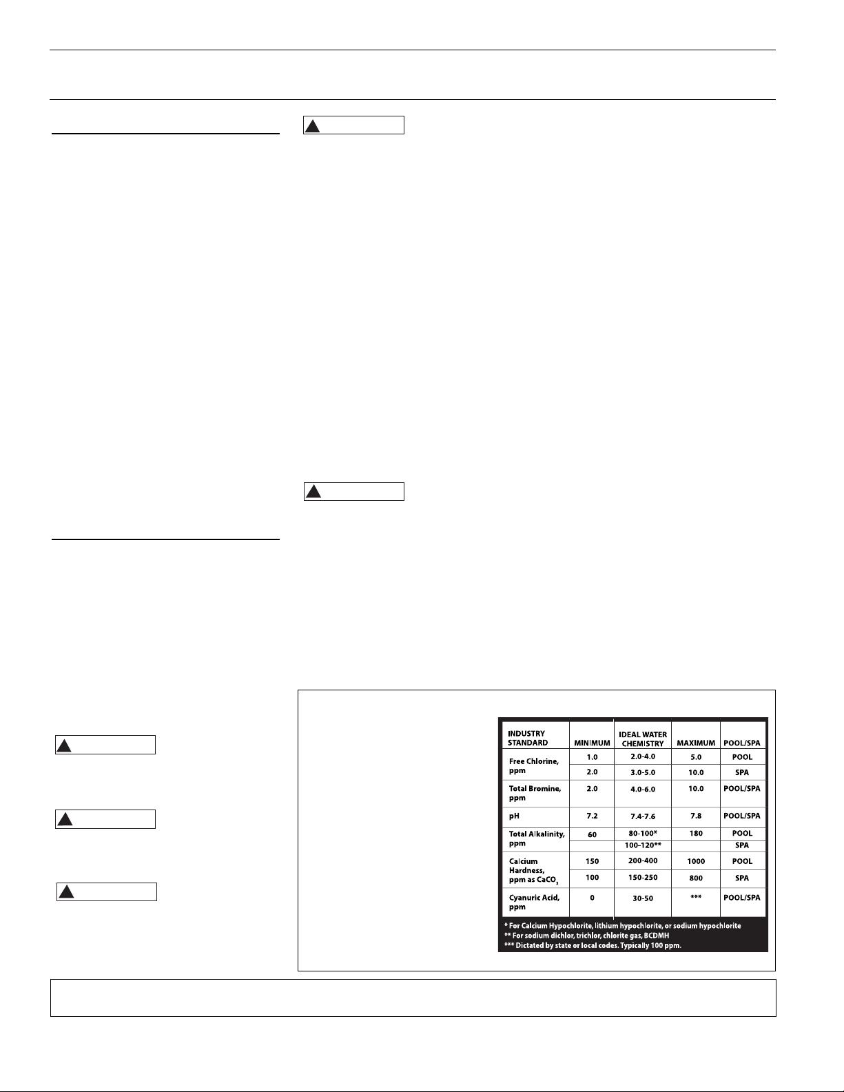
Pool Chemistry and Warranty (PRO400 & PRO600)
Maintaining pool chemistry at
the correct levels is critical for
health and pool/spa equipment
reasons. Failure to maintain
industry recognized standards
for proper pool chemistry will
void your warranty on the
PRO400 & PRO600. This chart
contains the recommended
levels for a typical pool. If you
have questions about
maintaining your pool and its
chemistry, consult your local
APSP/NSPI pool professional or
call 877-278-2797 to talk to an
AquaPro representative.
2
www.aquaprosystems.com 1-877-AQUASYS
!
WARNING
!
CAUTION
!
CAUTION
!
WARNING
!
CAUTION
Installation
Procedures
Unit Inspection
Inspect your unit very carefully before
installing. Make sure there has been no
damage to the evaporator fins or there
are no punctures or oil-soaked areas on
the box. This would indicate damage to
the refrigeration system and should be
rejected immediately.
THE UNIT MUST BE TRANSPORTED IN
THE UPRIGHT POSITION AT ALL
TIMES AND MUST NOT BE DROPPED
OR TAILGATED. DAMAGE TO THE
UNIT DURING TRANSPORTATION IS
NOT THE RESPONSIBILITY OF THE
MANUFACTURER.
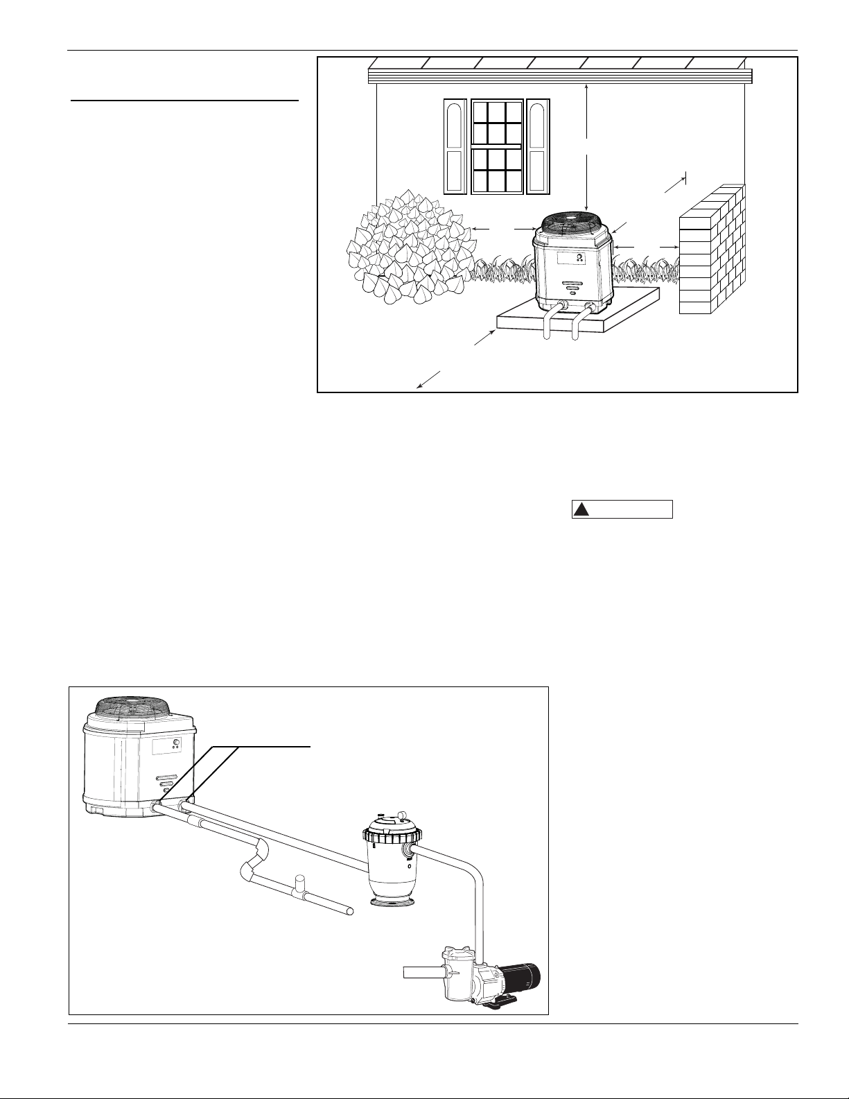
Unit Location
Once the unit has been inspected and
cleared of any transportation damage,
it is now time to locate the pool
heater. It is very important to
understand the location of the unit for
the best performance of operation.
See Figure 1 for location
recommendations.
A minimum of 18” of clearance
between the evaporator coils and
shrubs, fences, walls, etc. must be
maintained for adequate air intake.
A minimum of 5’ of vertical clearance
between the top of the unit and any
roof overhang or other obstructions
must be maintained in order to
prevent the re-circulation of cold air
back into the evaporator coils. This is
to maintain the efficiency of the unit.
A minimum of 36” of clearance
between the front of the unit (access
panel area) and any obstruction must
be maintained to allow maintenance
on the unit when necessary.
The unit should be located on a solid
level surface, a minimum of 36”x 36”
for proper drainage.
Make sure any sprinkler heads are not
directly spraying water on the unit.
While heat pumps are made for an
outdoor environment, they are not
designed to have sprinkler water
constantly spraying them. NOTE: This
type of constant watering directly
on the unit can void your warranty.
Condensation drain holes are provided
3
in all units for adequate removal of
condensation and rainwater. ALL
UNITS WILL HAVE CONDENSATION.
THIS SHOULD NOT BE MISTAKEN
FOR A LEAK IN THE UNIT.
Plumbing
Where freezing weather is encountered,
the detachable connection/union
(provided on PRO1000) must be installed
immediately adjacent to the heater to
facilitate servicing and draining of the
heat exchanger. Draining is necessary
to prevent damage to the condenser
shell and coil due to the expansion
of freezing water.
The minimum water circulation
capacity flowing through the pool
heater is 25 gallons per minute and the
maximum capacity is 80 gallons per
minute.
Do not install a water shutoff valve in
the piping from the outlet of the pool
heater to the pool or spa. However, a
check valve that does not include a
shut-off feature may be installed for
convenience during servicing.
A check valve or Hartford Loop is
recommended between the unit and a
chlorinator. The chlorinator must be
downstream of the heat pump. Failure
to do so may void the warranty.
If you have an in-floor cleaning system,
please take note of any special
plumbing requirements to operate all
units effectively.
Figure 2 shows the recommended
installation layout.
www.aquaprosystems.com
PRO400, PRO600, PRO1000
5’ Minimum
18” Min.
18”
Min.
36”Min.
18”
Min.
Figure 1 - Unit Location
Figure 2 - Recommended installation layout
FILTER
POOL
PUMP
CHLORONATOR
WARM
WATER OUT
TO POOL
COLD WATER
IN FROM POOL
IN
OUT
CHECK
VALVE
1-877-AQUASYS
UNIONS (INCLUDED WITH PRO1000)
!
CAUTION
4
Basic Heat Pump
Operation
Electrical Connections
All wiring and
electrical
connections must be performed by a
qualified electrician. Installations must
be in accordance with local and
national codes.
Overheating, short-
circuiting and fire
damage will result from inadequate
wiring.
All units are equipped with an electrical
wiring schematic inside the electrical
panel. If this is missing, please contact
the factory at 1-877-278-2797 to obtain
one.
All units are to be wired for 230 VAC,
1 phase. Please see following chart for
correct amperage:
Pool Heater is to be installed in
accordance with Article 680 of the
National Electrical Code (NEC), NFPA
70, and within the requirements of all
local codes having jurisdiction.
www.aquaprosystems.com
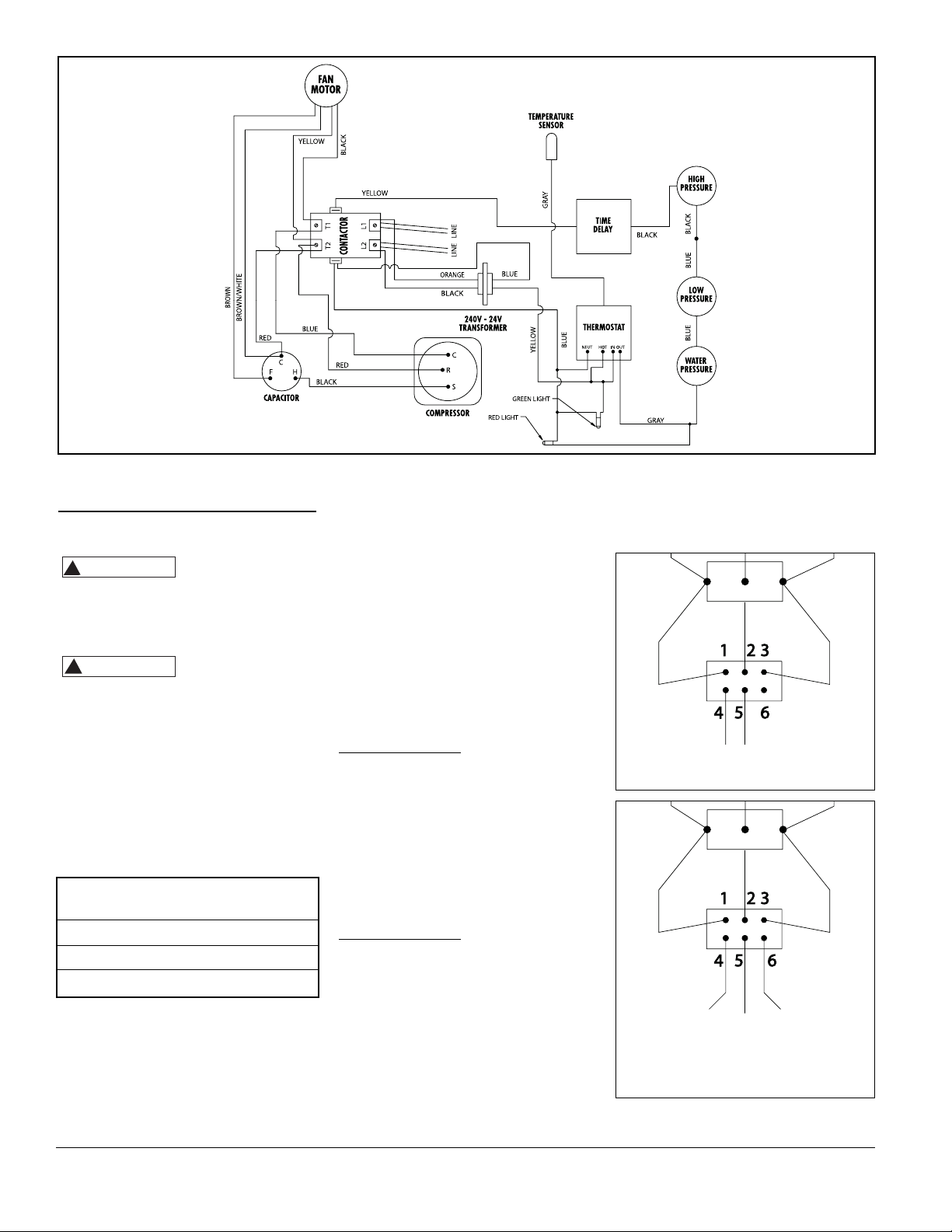
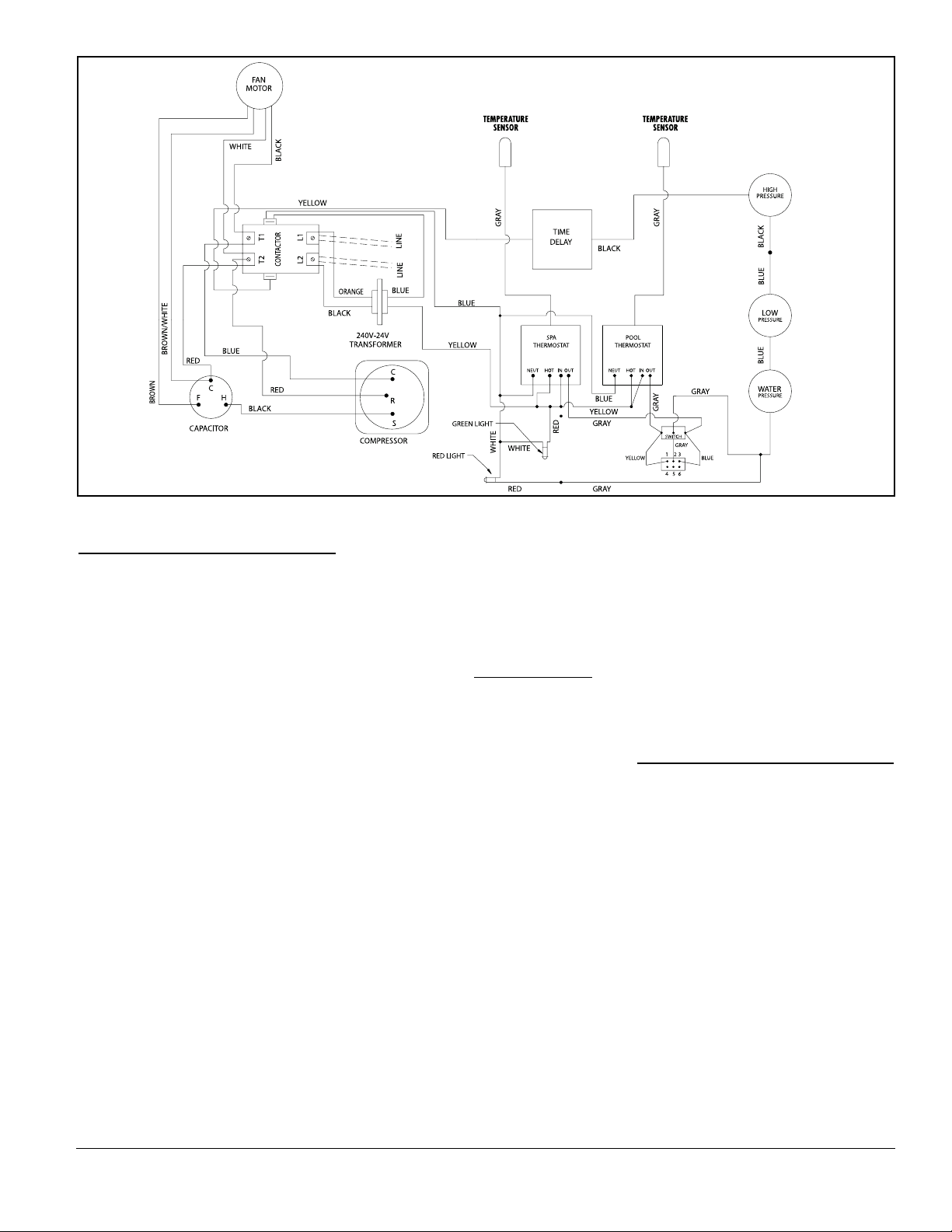
Figure 3 - PRO400 & PRO600 Wiring Diagram
See Figure 3 for wiring schematic of
PRO400 & PRO600. See Figure 6 for
wiring schematic of PRO1000.
Connecting to Remote
System (PRO1000 only)
The PRO1000 Pool Heater is compatible
with all known remote systems in the
pool industry. If you have or add a
remote system to your pool, please
review these instructions for wiring
and setting the thermostats on your
pool heat pump. You will need to
know if your remote system is a 2 wire
or a 3 wire system.
For 2 wire remotes
1. Turn the “pool” and “spa”
thermostat up to their highest
settings
2. Switch the toggle to “off” setting
3. See figure 4 for wiring diagram of
2 wire remote system
4. Connect remote system’s 2 wires to
the 4 & 5 positions on the terminal
block.
For 3 wire remotes
1. Turn the “pool” thermostat to the
desired pool temperature.
2. Turn the “spa” thermostat to the
desired spa temperature
3. Switch the toggle to the “off”
setting.
4. See figure 5 for wiring diagram of
3 wire remote system
5. Connect the low (or pool) wire to
position 4 on the terminal block.
Operating Instructions
Figure 4 - Connecting to a 2 wire
remote system
SWITCH
Blue
Yellow
Figure 5 - Connecting to a 3 wire
remote system
SWITCH
Blue
Yellow
High
(Spa)
Common
Low
(Pool)
6. Connect the high (or spa) wires to
position 6 on the terminal block.
7. Connect the common wire to
position 5 on the terminal block.
Gray
Gray
P S
1-877-AQUASYS
BREAKER
OR FUSE
HEAT
PUMP
20-ampPRO400
30-ampPRO600
50-ampPRO1000
!
WARNING
!
CAUTION
that power to the unit is on. The
RED light indicates that the unit is
in heating mode.
• The RED light may become
illuminated prior to heater start up.
The RED light will become lit when
the thermostat knob is set at or
above the water temperature.
• The unit has a built in time delay
.
Every time the unit turns off there is
a five-minute time delay until the
unit may be restarted. The HEAT
light may turn on during this delay
cycle. Do not rotate the thermostat
knob during this time delay.
Rotating the knob during this cycle
may reset the time delay, causing
the unit to wait an additional five
minutes prior to startup.
Water Temperature Set
Point
• Temperature set point range is 45°F
to 107°F. Rotating the thermostat
knob clockwise will increase the
temperature set point, while
rotating counterclockwise will
decrease the temperature set point.
• A floating thermometer may be
placed in the pool or spa to monitor
water temperature.
• To initially calibrate the thermostat
to the desired set point, turn the
thermostat knob fully clockwise.
The unit will turn on and begin
heating after a possible five minute
time delay. Allow the unit to run
until pool or spa water reaches the
desired temperature. Slowly turn
thermostat knob counterclockwise
until the unit turns off. The unit will
now maintain this water
temperature, providing the
circulation pump is running.
Application
Guidelines
Maintenance
All heat pumps are designed for
outdoor use. However, some
maintenance is required to maintain
the full life of the heater and is
necessary to maintain your warranty.
Annual maintenance should be
scheduled to make sure blowing sand
or falling debris is removed from the
inside of the heater. Rinsing the coil
down monthly with low water pressure
will help keep the base of the unit clear
of debris. Do not use a high pressure
washer. This can cause damage to your
evaporator coils and will void your
warranty. It is recommended that a
licensed air conditioning specialist
perform the annual planned
maintenance on your heater.
Manual Temperature
Controls
Description PRO400 & PRO600
• The manual Temperature Control is
designed to regulate pool and spa
water temperature.
• There are two indicator lights on
the control panel to display the
current status of the unit.
• The thermostat knob may be
adjusted to maintain the desired
water temperature.
Description - PRO1000
• With the PRO1000, you have a pool
and a spa thermostat and a 3position toggle switch.
• Use the toggle switch to select the
pool, spa and off settings.
• The thermostat knobs may be
adjusted to maintain the desired
water temperature.
• See “Connecting to a Remote
System” for toggle position and
thermostat position when this unit
is hooked up to a remote system.
Indicator Lights
• There are two indicator lights on
the front panel that display unit
status. The GREEN light indicates
PRO400, PRO600, PRO1000
5
www.aquaprosystems.com
Figure 6 - PRO1000 Wiring Diagram
1-877-AQUASYS
 Loading...