


Model 55011-7
OWNER’S MANUAL
UTILITY SINK PUMP
Questions, problems, missing parts? Before returning to the store call AQUAPRO
Customer Service 8 a.m. - 5 p.m., EST, Monday-Friday
1-844-242-2475
© 2015 Copyright GP Enterprises Co., Ltd.

PERFORMANCE
Model |
HP |
GPH of Water @ Total Feet Of Lift |
|
Max. Lift |
||
|
||||||
0 ft. |
5 ft. |
|
10 ft. |
|||
|
|
|
|
|||
55011-7 |
1/3 |
1300 |
950 |
|
550 |
15 ft. |
SAFETY INSTRUCTIONS
1.Do not pump flammable or explosive liquids such as oil, gasoline, kerosene, ethanol, etc. Do not use in the presence of flammable or explosive vapors. Using this pump with or near flammable liquids can cause an explosion or fire, resulting in property damage, serious personal injury, and/or death.
2.ALWAYS disconnect the power to the pump before servicing.
3.Do not touch the motor housing during operation. The motor is designed to operate at high temperatures. Do not disassemble the motor housing.
4.Do not handle the pump or pump motor with wet hands or when standing on a wet or damp surface, or in water before disconnect the power.
5.Release all pressure and drain all water from the system before servicing any component.
6.Secure the discharge line before starting the pump. An unsecured discharge line will whip, possibly causing personal injury, and/or property damage.
7.Extension cords may not deliver sufficient voltage to the pump motor. Extension cords present a life threatening safety hazard if the insulation becomes damaged or the connection ends fall into water. The use of an extension cord to power this pump is not permitted.
8.Wear safety goggles at all times when working with pumps.
9.This unit is designed only for use on 115 volts (single phase), 60 Hz, and is equipped with an approved 3-conductor cord and 3-prong grounded plug. Do not remove the ground pin under any circumstances. The 3-prong plug must be directly inserted into a properly installed and grounded 3-prong, grounding-type receptacle. Do not use this pump with a 2-prong wall outlet. Replace the 2-prong outlet with a properly grounded 3-prong receptacle (a GFCI outlet) installed in accordance with the National Electrical Code and local codes and ordinances. All wiring should be performed by a qualified electrician.
10.Protect the electrical cord from sharp objects, hot surfaces, oil, and chemicals. Avoid kinking the cord. Do not use damaged or worn cords.
11.Failure to comply with the instruction and designed operation of this unit may void the warranty. ATTEMPTING TO USE ADAMAGED PUMP can result in property damage, serious personal injury, and/or death.
12.Ensure that the electrical circuit to the pump is protected by a 15 Amp fuse or circuit breaker.
13.Do not lift the pump by the power cord.
14.Know the pump and its applications, limitations, and potential hazards.
15.Periodically inspect the pump and system components to ensure the pump suction screen is free of mud, sand, and debris. Disconnect the pump from the power supply before inspecting.
16.Follow all local electrical and safety codes, along with the National Electrical Code (NEC). In addition, all Occupational Safety and Health Administration (OSHA) guidelines must be followed.
17.The motor of this pump has a thermal protector that will trip if the motor becomes too hot. The protector will reset itself once the motor cools down and an acceptable temperature has been reached. The pump may start unexpectedly if it is plugged in.
2
18.Ensure the electrical power source is adequate for the requirements of the pump.
19.This pump is made of high-strength, corrosion-resistant materials. It will provide trouble-free service for a long time when properly installed, maintained, and used. However, inadequate electrical power to the pump, dirt, or debris may cause the pump to fail. Please carefully read the manual and follow the instructions regarding common pump problems and remedies.
20.This pump does not require a connection to a main stack vent, per the National Standard Plumbing Code (NSPC) 2003 Section 11.7.9.
PRE-INSTALLATION
APPLICATION
This pump is designed to be used with a sink where a gravity drain line is not available. Attach the pump to the drain tail piece; the pump will start when water begins to drain. Uses include basement laundry sinks, wet bars and utility sinks.
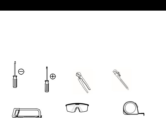
TOOLS REQUIRED
Flathead |
Phillips |
Channel |
Pipe wrench |
|
Screwdriver |
Screwdriver |
Locks |
||
|
|
Safety goggles |
Tape Measure |
Hacksaw |
|
|
SPECIFICATIONS |
|
|
|
|
|
Power supply |
115V, 60 HZ., 15 Amp Circuit |
|
|
|
|
Liquid temp. range |
32 to 77°F (0- 25°C) |
|
|
||
|
|
|
Pump Inlet |
1-1/2 in. NPT |
|
|
||
Pump discharge |
1-1/4 in. NPT |
|
|
||
|
|
|
3
INSTALLATION
(SEE FIGURES 1 AND 2)
WARNING: Electric Shock Hazard. Plug pump into a properly grounded, GFCI protected outlet. Do NOT plug in the pump until after it is completely installed. Do not remove or modify the grounding pins on the plugs.
Fittings Supplied: |
Qty. |
A Sink Drain Screen |
1 |
B 1-1/4” NPT x 1-1/4” Slip Check Valve |
1 |
C 1-1/4” NPT Ball Valve |
1 |
|
|
|
|
|
|
|
|
|
|
|
|
|
|
|
|
|
|
|
|
|
|
|
|
|
|
|
Purchase Separately: |
|
Qty. |
|
|
|
|
|
|
|
|
|
|
|
|
|
|
|
|
|
|
|
|
|
|
|
|
|
|
|
|
||
|
|
|
|
|
|
|
|
|
|
|
|
|
|
|
|
|
|
|
|
|
|
|
|
|
|
|
|
||
|
|
|
|
|
|
|
|
|
|
|
|
|
|
|
|
|
|
|
|
|
|
|
|
|
|
|
|
||
|
|
|
|
|
|
|
|
|
|
|
|
|
|
|
|
|
|
|
|
|
|
|
|
|
|
|
|||
|
|
|
|
|
|
|
|
|
|
|
|
|
|
|
|
|
|
|
|
|
|
|
|
|
|
|
1 1-1/2” NPT x 1-1/2” Slip Female Adapter |
1 |
|
|
|
|
|
|
|
|
|
|
|
|
|
|
|
|
|
|
|
|
|
|
|
|
|
|
|
|
|||
|
|
|
|
|
|
|
|
|
|
|
|
|
|
|
|
|
|
|
|
|
|
|
|
|
|
|
2 1-1/2” Schedule 40 PVC Pipe, to fit |
|
1 |
|
|
|
|
|
|
|
|
|
|
|
|
|
|
|
|
|
|
|
|
|
|
|
|
|
|
|
|
||
|
|
|
|
|
|
|
|
|
|
|
|
|
|
|
|
|
|
|
|
|
|
|
|
|
|
|
|||
|
|
|
|
|
|
|
|
|
|
|
|
|
|
|
|
|
|
|
|
|
|
|
|
|
|
|
3 1-1/2” NPT x 1-1/2” Slip Male Adapter |
|
1 |
|
|
|
|
|
|
|
|
|
|
|
|
|
|
|
|
|
|
|
|
|
|
|
|
|
|
|
|
||
|
|
|
|
|
|
|
|
|
|
|
|
|
|
|
|
|
|
|
|
|
|
|
|
|
|
|
4 1-1/4” NPT Galvanized Nipple (to fit) |
|
1 |
|
|
|
|
|
|
|
|
|
|
|
|
|
|
|
|
|
|
|
|
|
|
|
|
|
|
|
|||
|
|
|
|
|
|
|
|
|
|
|
|
|
|
|
|
|
|
|
|
|
|
|
|
|
|
|
5 1-1/4” NPT Galvanized Union |
|
1 |
|
|
|
|
|
|
|
|
|
|
|
|
|
|
|
|
|
|
|
|
|
|
|
|
|
|
|
|||
|
|
|
|
|
|
|
|
|
|
|
|
|
|
|
|
|
|
|
|
|
|
|
|
|
|
|
|||
|
|
|
|
|
|
|
|
|
|
|
|
|
|
|
|
|
|
|
|
|
|
|
|
|
|
|
|||
|
|
|
|
|
|
|
|
|
|
|
|
|
|
|
|
|
|
|
|
|
|
|
|
|
|
|
6 1-1/4” NPT x 1-1/4” Male Adapter |
|
1 |
|
|
|
|
|
|
|
|
|
|
|
|
|
|
|
|
|
|
|
|
|
|
|
|
|
|
|
|||
|
|
|
|
|
|
|
|
|
|
|
|
|
|
|
|
|
|
|
|
|
|
|
|
|
|
|
|||
|
|
|
|
|
|
|
|
|
|
|
|
|
|
|
|
|
|
|
|
|
|
|
|
|
|
|
7 1-1/4” Schedule 40 PVC Pipe, to fit |
|
1 |
|
|
|
|
|
|
|
|
|
|
|
|
|
|
|
|
|
|
|
|
|
|
|
|
|
|
|
|||
|
|
|
|
|
|
|
|
|
|
|
|
|
|
|
|
|
|
|
|
|
|
|
|
|
|
|
8 1-1/4” Socket to Socket 90° Elbow |
|
1 |
|
|
|
|
|
|
|
|
|
|
|
|
|
|
|
|
|
|
|
|
|
|
|
|
|
|
|
9 1-1/4” Schedule 40 PVC Pipe to Drain |
|
As Needed |
|
|
|
|
|
|
|
|
|
|
|
|
|
|
|
|
|
|
|
|
|
|
|
|
|
|
|
PVC Pipe Cement |
|
As Needed |
|
|
|
|
|
|
|
|
|
|
|
|
|
|
|
|
|
|
|
|
|
|
|
|
|
|
|
|||
|
|
|
|
|
|
|
|
|
|
|
|
|
|
|
|
|
|
|
|
|
|
|
|
|
|
|
PTFE pipe thread sealant tape |
|
As Needed |
|
|
|
|
|
|
|
|
|
|
|
|
|
|
|
|
|
|
|
|
|
|
|
|
|
|
|
|
||
|
|
|
|
|
|
|
|
|
|
|
|
|
|
|
|
|
|
|
|
|
|
|
|
|
|
|
1-1/2” PVC Solvent Union – optional |
As Needed |
|
NOTE: Be careful to avoid cross-threading; Use only a plastic-compatible pipe-threading compound or teflon tape when connecting threaded fittings to plastic adapters.
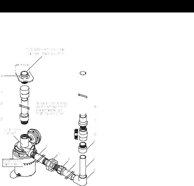
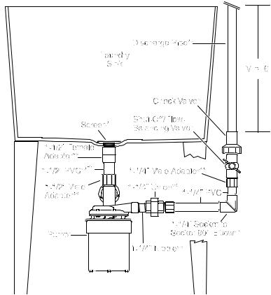
Figure 1: Typical method of mounting the pump
4
Mount the pump
NOTE: DO NOT use plumber’s pipe threading compound (“pipe dope”) on plastic pipe; it can damage the plastic, causing leaks and piping failure and void the warranty.
1.Place the sink in its final location.
2.Remove any existing drain fittings back to the tail piece. Make sure the existing tail piece does not leak. NOTE: If the sink-drain tail piece is not 1-1/2 in. NPT, you will have to adapt it (bushings, reducers, etc.). In this case, wrap all joints with PTFE pipe thread sealant tape before making connections.
3.Glue the 1-1/2 in. PVC pipe into the female adapter (purchase separately).
WARNING: Fire and explosion hazard. Be sure to follow the cement manufacturer’s instructions when using PVC cement. Do not use near fire or open flame.
4.Wrap the threads of the tail piece with 1 to 1-1/2 turns of PTFE pipe thread sealant tape. Thread the 1-1/2 in. NPT female adapter onto the sink-drain tail piece. Thread it hand tight plus 1/2 turn with a pipe wrench or slip joint pliers. DO NOT over tighten.
* Required and included ** Purchase separately
† For easier removal for servicing or cleaning, install a 1-1/2 in. solvent union in the drop pipe.
NOTE: The vertical height from the check valve to the pipe outlet should be at least 6.5ft to void check valve leakage.
5.Wrap the threads of the 1-1/2 in. male adapter with 1 to 1-1/2 turns of PTFE pipe thread sealant tape and install it in the pump inlet. Tighten it hand tight plus 1/2 turn with a pipe wrench or slip joint pliers. DO NOT over tighten!
6.Measure the 1-1/2 in. PVC pipe against the drain and the pump and trim the pipe to fit.
7.Do a trial assembly (dry - no glue) of the pump onto the drain pipe. Swing the pump until it accurately faces the discharge piping, and then mark the pump and the inlet pipe/adapter assembly so that you can accurately install the pump in Step 8. Arrange a temporary support under the pump to relieve the strain on the sink drain piping
while the glue is setting. Leave it in place while you measure and cut the discharge piping (Step 12). 5

8.Slide the pump up into position and glue the pipe into the male adapter (on the pump). •No glue on the pump or in the motor;
•Make sure the pump is facing the right direction (match the marks from Step 7);
•Put the support in place under the motor.
9.Wrap the 1-1/4 in. galvanized nipple with 1-1/2 to 2 turns of PTFE pipe thread sealant tape on each end and
thread it into the pump discharge port.
NOTE: Tighten this only enough to prevent leaking. Over-tightening can crack the plastic.
10.Hold the nipple with a pipe wrench and thread one half of the 1-1/4 in. union onto it, hand tight plus 1-1/2 turns with a pipe wrench or slip-joint pliers.
11.At this time, wrap the threads on both the 1-1/4in. male adapters with 1-1/2 to 2 turns of PTFE pipe thread sealant tape. Thread one of the adapters into the other half of the 1-1/4 in. union, hand tight plus 1/2 turn with a wrench or a pair of slip-joint pliers. DO NOT over tighten!
12.Install the discharge piping as shown in Figures 1 and 2. The order is:
a.1-1/4 in. PVC Pipe cut to fit
b.90° Soc. to Soc. elbow
c.1-/14 in. PVC Pipe cut to fit
d.Male adapter
e.Flow Control/Ball Valve, Check Valve
NOTE: Install the check valve in the vertical discharge pipe with the threads down. Be sure the flow arrow points AWAY from the pump. That is, when the check valve is correctly installed, the arrow showing direction of flow should point UP.
f. 1-1/4 in. Outlet Pipe
13.Connect the discharge piping to the building drain.
OPERATION
Plug in the Pump
AFTER the pump is completely installed, plug the switch into a GFCI protected, properly grounded outlet. Plug the pump into the back of the switch’s plug.
Adjusting the Flow
The drain pump can pump up to 21 gallons per minute (GPM). Normal sink drains allow only 5 to 6 GPM to flow. Adjust the discharge shut-off/flow balancing valve as follows so that the pump does not cycle on and off when the faucets are on full.
Run water into the sink. The pump will start when it detects water.
Check for leaks. If leaks are found, unplug the pump power cord and fix the leaks before proceeding.
Put a stopper in the drain and allow the sink to fill up a few inches.
Open the discharge shut-off valve, open the faucets, and remove the stopper to drain the sink.
The pump will start. Adjust the discharge shut-off/flow balancing valve until the pump runs continuously while the faucets are running and the sink is draining. If the water level rises with the pump on, slightly open the discharge valve to balance the flow. If it drops, slightly close the discharge valve.
6
 Loading...