


PRO1300
AquaPRO PRO1300, PRO1100e TCE, PRO1300h-c, PRO1100e, PRO1300h-c TCE User Manual
...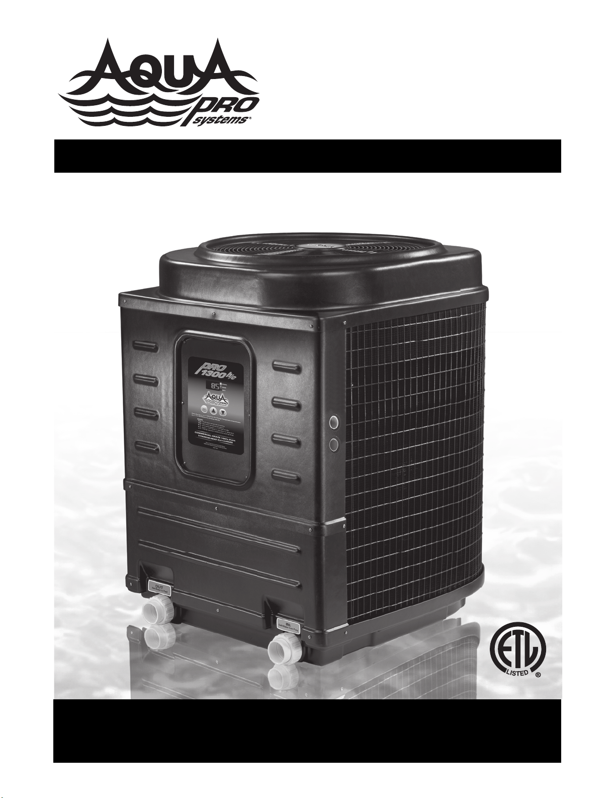
HEAT PUMP POOL HEATER
BOMBA DE CALOR PARA PISCINAS
PRO1100, PRO1100e, PRO1300, PRO1300h/c, PRO1100e TCE, PRO1300 TCE, PRO1300h/c TCE
101 Production Drive, Harrison, OH 45030 877.278.2797 fax 877.289.2963
cs@aquaprosystems.com www.aquaprosystems.com
OWNER’S MANUAL MANUAL DEL USUARIO

.
REMINDER: Keep your dated proof of purchase for warranty purposes! Attach it to this manual or file it for safekeeping.
Please read and save these instructions. Read carefully before attempting to assemble, install, operate or maintain the product described.
Protect yourself and others by observing all safety information. Failure to comply with instructions could result in personal injury and/or
property damage! Retain instructions with owner for future reference.
Important Safety Instructions . . . . . . 1
Installation Procedures . . . . . . . . . 1 - 2
Unit Inspection . . . . . . . . . . . . . . . . 1
Unit Location . . . . . . . . . . . . . . . . . 2
Plumbing . . . . . . . . . . . . . . . . . . . . . 2
Basic Heat Pump Operation . . . . . 2 - 3
Electrical Connections . . . . . . . . 2 - 3
Electronic Temp. Controls . . . . . . . . 3
- Description . . . . . . . . . . . . . . . . . 3
- Buttons . . . . . . . . . . . . . . . . . . . . 3
- Water Temp. Set Point . . . . . . . . 3
Connecting to a Remote System. . .3
High Temperature Lock Out . . . . . . 3
SPECIFIC MODEL DETAILS
PRO1100 . . . . . . . . . . . . . . . . . . . . . 4
Wiring Diagram . . . . . . . . . . . . . . . . 4
Manual Temp. Controls . . . . . . . . . 4
PRO1300 & PRO1100e . . . . . . . . . 5
Wiring Diagram . . . . . . . . . . . . . . . . 5
PRO1300h/c . . . . . . . . . . . . . . . . 5 - 6
Wiring Diagram . . . . . . . . . . . . . . . . 5
Toggling Between Heat/
Cool Mode . . . . . . . . . . . . . . . . . . . 6
Defrost Cycle . . . . . . . . . . . . . . . . . . 6
PRO1300 TCE/ PRO1100e TCE. . . . 6 - 7
Selecting Functionality of Unit . . . . 6
TCE Operation . . . . . . . . . . . . . . . . . 6
TCO Operation . . . . . . . . . . . . . . 6 - 7
Wiring Diagram . . . . . . . . . . . . . . . . 7
PRO1300h/c TCE . . . . . . . . . . . . 8 - 9
Wiring Diagram . . . . . . . . . . . . . . . . 8
Toggling Between Heat/
Cool Mode . . . . . . . . . . . . . . . . . . . 8
Defrost Cycle . . . . . . . . . . . . . . . . . . 8
Selecting Functionality of Unit . . . . 8
TCE Operation . . . . . . . . . . . . . . 8 - 9
TCO Operation . . . . . . . . . . . . . . . . 9
Application Guidelines . . . . . . . . 9 - 10
Maintenance . . . . . . . . . . . . . . . . . . 9
Condensation . . . . . . . . . . . . . 9 - 10
Pool Blankets . . . . . . . . . . . . . . . . 10
Seasonal Shutdowns . . . . . . . . . . 10
Pool Openings . . . . . . . . . . . . . . . 10
Weather Conditions . . . . . . . . . . . 10
Troubleshooting Guide . . . . . . . 10 - 11
- Diagnostics . . . . . . . . . . . . . 10 - 11
Warranty . . . . . . . . . . . . . . . . . . . . . . 12
322902-013 2/08
© 2008 AquaPRO®Systems
For parts, product & service information
visit www.aquaprosystems.com
Important Safety
Instructions
READ AND FOLLOW ALL
INSTRUCTIONS.
Safety Guidelines
This manual contains information that is
very important to know and understand.
This information is provided for SAFETY
and to PREVENT EQUIPMENT PROBLEMS.
To help recognize this information,
observe the following symbols.
Warning
indicates a
potentially hazardous situation which, if
not avoided, could result in death or
serious injury.
Caution
indicates a
potentially hazardous situation which, if
not avoided, may result in minor or
moderate injury.
Notice
indicates
important information, that if not
followed, may cause damage to
equipment.
CALIFORNIA PROPOSITION 65
This
product or
its power cord may contain chemicals
known to the State of California to
cause cancer and birth defects or other
reproductive harm. Wash hands after
handling.
GENERAL SAFETY INFORMATION
• The water in a pool or tub should never
exceed 104ºF (40ºC). A water
temperature in excess of 104ºF is
considered unsafe for all persons. Lower
water temperatures are recommended
for extended use (exceeding 10 - 15
minutes) and young children.
• Excessive water temperatures have a
high potential for causing fetal damage
during the early months of pregnancy.
Pregnant or possibly pregnant women
should limit pool or tub water
temperatures to 100ºF (38ºC).
• Alcohol, drugs, or medication should
not be used before or during pool or
tub use since their use may lead to
unconsciousness with the possibility
of drowning.
• Obese persons and persons with a
medical history of heart disease, low or
high blood pressure, circulatory system
problems, or diabetes should consult a
physician before using a pool or tub.
• Persons using medication should
consult a physician before using a pool
or tub since some medication may
induce drowsiness while other
medication may affect heart rate,
blood pressure, and circulation.
• Prolonged immersion in hot water may
induce hyperthermia. Hyperthermia
occurs when the internal temperature
of the body reaches a level several
degrees above the normal body
temperature of 98.6ºF. The symptoms
of hyperthermia include dizziness,
fainting, drowsiness, lethargy, and an
increase in the internal temperature of
the body. The effects of hyperthermia
include: unawareness of impending
hazard; failure to perceive heat; failure
to recognize the need to exit pool or
tub; physical inability to exit pool or
tub; fetal damage in pregnant women;
and unconsciousness resulting in a
danger of drowning.
• Because the tolerance of water
temperature-regulating devices may
vary as much as ±5ºF (±3ºC), you
should measure the water
temperature at several locations
using an accurate thermometer
before entering a pool or tub.
SAVE THESE INSTRUCTIONS.
Installation Procedures
Unit Inspection
Inspect your unit very carefully before
installing. Make sure there has been
no damage to the evaporator fins or
there are no punctures or oil-soaked
areas on the box. This would indicate
damage to the refrigeration system
and should be rejected immediately.
Contents
Heat Pump
Pool and Spa Heater
Operating Instructions
PRO1300, PRO1100e, PRO1300h/c, PRO1100,
PRO1300h/c TCE, PRO1300 TCE, PRO1100e TCE
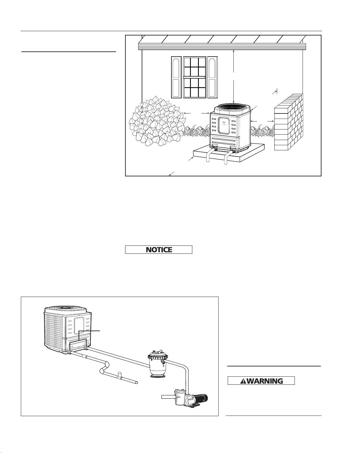
Figure 2 Recommended installation layout
POOL
HEATER
UNIONS
FILTER
POOL
PUMP
CHLORONATOR
WARM
WATER OUT
TO POOL
COLD WATER
IN FROM POOL
IN
OUT
CHECK
VALVE
THE UNIT MUST BE TRANSPORTED
IN THE UP-RIGHT POSITION AT ALL
TIMES AND MUST NOT BE DROPPED
OR TAILGATED. DAMAGE TO THE
UNIT DURING TRANSPORTATION IS
NOT THE RESPONSIBILITY OF THE
MANUFACTURER.
Unit Location
Once the unit has been inspected and
cleared of any transportation damage,
it is now time to locate the pool heater.
It is very important to understand the
location of the unit for the best
performance of operation. See Figure 1
for location recommendations. A
minimum of 18" of clearance between
the evaporator coils and shrubs, fences,
walls, etc. must be maintained for
adequate air intake. A minimum of 5' of
vertical clearance between the top of
the unit and any roof overhang or other
obstructions must be maintained in
order to prevent the re-circulation of
cold air back into the evaporator coils.
This is to maintain the efficiency of the
unit. A minimum of 36" of clearance
between the front of the unit (access
panel area) and any obstruction must
be maintained to allow maintenance on
the unit when necessary. The unit
should be located on a solid level
surface, a minimum of 36"x 36" for
proper drainage. Make sure any
sprinkler heads are not directly spraying
water on the unit. While heat pumps
are made for an outdoor environment,
they are not designed to have sprinkler
water constantly spraying them.
NOTE: This type of constant
watering directly on the unit can
void your warranty.
Condensation drain holes are provided
in all units for adequate removal of
condensation and rainwater. ALL
UNITS WILL HAVE CONDENSATION.
THIS SHOULD NOT BE MISTAKEN
FOR A LEAK IN THE UNIT.
Plumbing
Where freezing weather is encountered,
the detachable connection/union
(provided) must be installed
immediately adjacent to the heater to
facilitate servicing and draining of the
heat exchanger. Draining is necessary
Phone: (877)-278-2797
2
Operating Instructions
to prevent damage to the
condenser shell and coil due to the
expansion of freezing water.
The minimum water circulation
capacity flowing through the pool
heater is 25 gallons per minute and
the maximum capacity is 80 gallons
per minute.
Do not install a water shutoff valve in
the piping from the outlet of the pool
heater to the pool or tub. However, a
check valve that does not include a
shut-off feature may be installed for
convenience during servicing.
A check valve or Hartford Loop is
recommended between the unit and a
chlorinator. The chlorinator must be
downstream of the heat pump. Failure
to do so may void the warranty.
If you have an in-floor cleaning
system, please take note of any special
plumbing requirements to operate all
units effectively.
Figure 2 shows the recommended
installation layout.
Basic Heat Pump
Operation
Electrical Connections
All
wiring
and electrical connections must be
performed by a qualified electrician.
Installations must be in accordance with
local and national codes.
www.aquaprosystems.com
5' Minimum
18" Min.
18"
Min.
36"Min.
18"
Min.
Figure 1 Unit Location
Installation Procedures
(continued)
36” clearance
18“ min
5 feet
(minimum)
18“ min
18“ min
www.aquaprosystems.com
Overheating, short-circuiting and fire
damage will result from inadequate
wiring.
All units are equipped with an
electrical wiring schematic inside the
electrical panel. If this is missing,
please contact the factory at 1-877278-2797 to obtain one.
All units are to be wired for 230 VAC, 1
phase. These units require a dedicated
50-amp breaker or time delay fuse.
Pool Heater is to be installed in
accordance with Article 680 of the
National Electrical Code (NEC), NFPA
70, and within the requirements of all
local codes having jurisdiction.
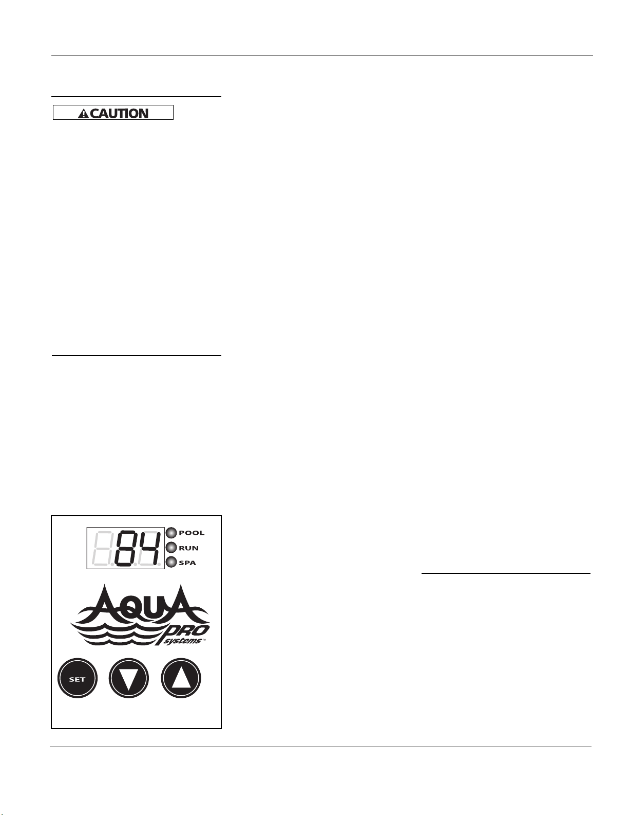
Electronic Temp.
Controls
All Units Except PRO1100
Description
• The control located on the front of
your heat pump has a large threecharacter display for the water
temperature, set points, and
diagnostics (see figure 3 for front
panel appearance). The three button
keypad includes SET, UP arrow, and
DOWN arrow buttons. LED indicators
next to the display show if the heat
pump is in the pool mode or in the
spa mode and if the unit is running.
Buttons
Press the SET button to change
between modes and use the up and
down arrows to change the selected
mode’s settings.
Modes available are:
POL - allows you to change the pool
water temperature set point
SPA - allows you to change the spa
water temperature set point
P-S - changes between pool and spa
settings. LED’s on front panel will
indicate current mode selected.
F-C - display temperature in
Fahrenheit or Celsius
TCE UNITS ONLY:
FIL - used to set system run time.
H/C UNITS ONLY:
H-C - change between heating and
cooling mode.
Water Temperature Set
Point
Temperature set point range is OFF, and
61°F to 95°F for POL mode. For SPA
mode, set point range is OFF, and 61°F to
104°F. Pushing the UP arrow or DOWN
arrow buttons will prompt the control to
display the current set point. Continuing
to press the UP or DOWN buttons will
allow the set point values to scroll until
the desired set point is reached. Once the
new set point has been reached, stop
pressing the UP or DOWN buttons. Once
the unit toggles back to the current
water temperature display, the set point
is entered. The controls have a feature
called “Set Point Memory Retention”. If
the power is removed from the unit, it
retains the last set point displayed.
Connecting to a Remote
System: All Units Except
Pro1100
This Pool Heater is compatible with all
known remote systems in the industry.
The following models’ diagrams show
how to connect all of the remote
systems to the Electronic Temp.
Controller.
For 2 wire remotes
1. Bring up “POL” setting and arrow
temperature down until pool setting
reads “off”.
2. Bring up “SPA” setting and arrow
temperature up until spa setting
reads 104.
3. Set unit to the “POL” mode.
4. Connect remote system with 2 wires
to the P/S terminal on control board
(see specific model wiring diagram).
For 3 wire remotes
1. Bring up “POL” setting and use
arrows to select desired pool
temperature.
2. Bring up “SPA” setting and use the
arrows to select the desired spa
temperature.
3. Set unit to the “POL” mode.
4. Connect the common and high (or
spa) wires to the “P/S” terminals on
control board (see specific model
diagram). Low or pool wire does not
get connected.
Note: For heat/ cool units, the remote
will not work in the cooling mode.
Connecting to Remote
Systems: PRO1100
This Pool Heater is compatible with 2wire remote systems only, and is not
compatible with 3 wire remote
systems. Figure 4 shows where to
connect the remote systems to the
Temperature Controller.
Connection to AquaLink, Compool,
Hayward, AquaLogic or any other 2
wire remote system with their own
thermostat:
• Remove gray jumper from terminals
1 and 2 on TB1.
• Bring the two wires from the remote
system to terminals 1 & 2 on Terminal
Block 1 (TB1).
• The Temperature Control knob must
be turned clockwise (highest temp.
setting) for the remote system to
operate the Pool Heater properly.
High Temperature Lock Out:
All Units Except PRO1100
Your heat pump includes a special
feature to “lock” the high
temperature settings. This eliminates
the need for a thermostat lock-box.
This prevents unauthorized persons
from adjusting the heat pump above
these desired limits. To activate this
feature, please call AquaPRO
®
Systems
at 877-AQUA-SYS (877-278-2797)
during business hours 8 AM to 5 PM
EDT Monday through Friday and we
will be glad to assist in setting up this
feature.
PRO1300, PRO1100e, PRO1300h/c, PRO1100,
PRO1300h/c TCE, PRO1300 TCE, PRO1100e TCE
Phone: (877)-278-2797
3
Figure 3 - Front Panel
Basic Heat Pump
Operation (continued)

Operating Instructions
www.aquaprosystems.com
Manual Temperature
Controls
Description
• The manual Temperature Control is
designed to regulate pool and spa
water temperature.
• There are two indicator lights on the
control panel to display the current
status of the unit.
• The thermostat knob may be
adjusted to maintain the desired
water temperature.
Indicator Lights
• There are two indicator lights on the
front panel that display unit status. The
GREEN light indicates that power to the
unit is on. The RED light indicates that
the unit is in heating mode.
Phone: (877)-278-2797
4
Figure 4 - PRO1100 wiring diagram
PRO1100
• The RED light may become
illuminated prior to heater start up.
The RED light will become lit when
the thermostat knob is set at or
above the water temperature.
• The unit has a built in time delay.
Every time the unit turns off there is a
five-minute time delay until the unit
may be restarted. The HEAT light may
turn on during this delay cycle. Do not
rotate the thermostat knob during this
time delay. Rotating the knob during
this cycle may reset the time delay,
causing the unit to wait an additional
five minutes prior to startup.
Water Temperature Set Point
• Temperature set point range is 45°F
to 107°F. Rotating the thermostat
knob clockwise will increase the
temperature set point, while rotating
counterclockwise will decrease the
temperature set point.
• A floating thermometer may be
placed in the pool or spa to monitor
water temperature.
• To initially calibrate the thermostat to
the desired set point, turn the
thermostat knob fully clockwise. The
unit will turn on and begin heating
after a possible five minute time delay.
Allow the unit to run until pool or spa
water reaches the desired temperature.
Slowly turn thermostat knob counterclockwise until the unit turns off. The
unit will now maintain this water
temperature, providing the circulation
pump is running.
Fan
Motor
Green
Light
Red
Llight
240V-24V
Transformer
Capacitor
Compressor
Thermostat
Time
Delay
Water
Pressure
Low
Pressure
High
Pressure
Black
Black
Black
Black
Black
White
Brown/ White
Brown
Blue
Blue
Blue
Blue
Blue
Yellow
Yellow
Gray
Gray
Gray
Gray
Red
Red
Orange
Nuet Hot In Out
T2 T1
Contractor
L2 L1
Line Line
Temp
1 2
TB1
3 4
C
F H
C
R
S
PRO1100
PRO1300, PRO1100e, PRO1300h/c, PRO1100,
PRO1300h/c TCE, PRO1300 TCE, PRO1100e TCE
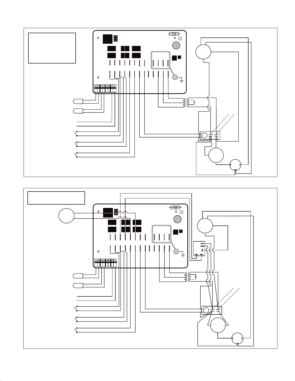
Figure 5 - PRO1100e & PRO1300 wiring diagram
Water Sensor
Defrost Sensor
High Pressure Switch
Closed = OK
Opened = High Pressure
Low Pressure Switch
Closed = OK
Opened = Low Pressure
Flow Switch
Closed = Flow
Opened = No Flow
MY-TECH PH-111A
Brown
Brown & White
SPR1
SPR2
REVR
JANDY
HP
LP FLO
COMP
PUMP
12 ~8 ~12
AC F1 F2 F3
WS
DSASP/S
Black
Black
Blue
Orange
Blue
Orange
Blue
Gray
12 VAC
Blue
Red
Blue
12 / 24 VAC
Transformer
Black
Yellow
Yellow
24
Vac
COMPRESSOR
R
S
C
24 VAC
Compressor
Contactor
Coil
Run Cap
L1
L2
Black
Black
Yellow
Black
Black
Red
H
C
F
Red
Blue
FAN
Black
Black
White
PRO1100e
and
PRO1300
Phone: (877)-278-2797
5
www.aquaprosystems.com
To Remote System
(If Applicable)
Figure 6 - PRO1300h/c wiring diagram
Water Sensor
Defrost Sensor
High Pressure Switch
Closed = OK
Opened = High Pressure
Low Pressure Switch
Closed = OK
Opened = Low Pressure
Flow Switch
Closed = Flow
Opened = No Flow
Red
Black
MY-TECH PH-111A
Brown
Brown & White
FAN
SPR1
SPR2
REVR
JANDY
HP
LP FLO
COMP
PUMP
12
~0 ~12
AC F1 F2
F3
WS
DSASP/S
White
White
Black
Black
Yellow
Orange
Yellow
Orange
Blue
Gray
12 VAC
Blue
Red
Blue
12 / 24 VAC
Transformer
Black
Yellow
Yellow
Yellow
24
Vac
COMPRESSOR
R
S
C
24 VAC
Compressor
Contactor Coil
Run Cap
L1L2
REVERSING
VALVE
Black
Black
NC
NO
COM
Black
Black
White
Yellow
Black
Orange
H
C
F
To Remote System
(If Applicable)
PRO1300h/c
Operating Instructions
Phone: (877)-278-2797
6
www.aquaprosystems.com
PRO1300h/c
Electronic Temp.
Controls
Toggling Between Heating
and Cooling Mode
The unit will default to the heating
mode. If the cooling mode is desired,
press the SET button until the H-C screen
is displayed. Then press the arrow
buttons until “COL” is displayed on the
screen. This puts the unit into cooling
mode. The water temperature set point
will now be the water temperature that
the unit is cooling the water to. When
the unit is in cooling mode, the screen
will flash between the current water
temperature and “COL” to remind the
user that cooling mode is activated.
Defrost Cycle
Your AquaPRO®h/c unit is capable of
keeping your pool warm in very cool
temperatures. Most pool heaters will
not operate below 50°F. Your h/c unit
will work down to 38°F by utilizing a
“defrost cycle”. It does this
automatically by sensing the coolant
temperature and reversing operation
for 2 minutes to defrost the evaporator
coil and will resume heating function
after defrosting the evaporator coil.
This section allows you to run the heat
pump at set intervals during the day. If
you have a time clock, and would like to
use it please refer to the Time Clock
Override section.
For the TCE feature to work, your pool
pump must be wired to the heat pump
See figure 7 for wiring the TCE feature
•
This unit is prepared at the factory
with the TCE feature installed, but
set to the “off” position in the “FIL”
mode. You will need to set the
hours of run time for the pump and
filter system. See “activating and
setting system run time” below.
•
The function of the TCE is done through
a timing sequence of 6 periods per
24 hours. You select the hours for your
required filter pump run time, and the
heater takes care of the rest. It does this
by dividing the system run time equally
over the 6 periods, turning the pump on
for 1/6th of the specified run time and
off the remainder of the period unless
additional heating is required. The
heater will always operate the system
on a daily basis for the amount of run
time you have selected. The timing
sequence begins at the initial start up.
•
If your pool is at or above the desired
operating temperature, the heater will
run the system the desired hours each
day and spread the time out evenly
between the 6 periods. This makes for
better filter operation and allows the
heater to update the water
temperature 6 times per day.
•
If your pool needs heat, the heater will
continue to run the system until the
desired temperature is met. If the
amount of run time exceeds a period’s
run time, the excess time will be
subtracted from the next run period(s).
Please note that on cold and / or windy
days, the unit could run for long times
to generate and maintain the desired
pool temperature. Please see the
“application” section about “pool
blankets” to help maintain your pool’s
temperature.
•
The timing function built into the TCE
will always run the heat pump for
15 minutes every 4 hours to determine if
more heat is needed to maintain the
pool’s desired temperature - even if all
of the available run time was used in
previous cycles. This provides a couple of
added benefits. Pools will lose most of
their heat at night if left uncovered,
however, since the unit is checking for
and adding heat when needed, it
prevents long recovery times when
compared to non-TCE units. The other
benefit is that some states and electric
utility companies offer a discount for
off-peak usage of electricity. Please
contact your electricity provider if you
have questions.
•
Example of TCE operation – you require
the system to run for 12 hours to meet
your pool filtering needs. This means for
each of the 6 periods, the heater will
run the system for 2 hours and then
turn off for 2 hours. If the system
needed to run for 3 hours in one of the
periods to reach the desired pool
temperature, the next period would be
1 hour on and 3 hours off unless
additional heating is needed. The cycle
continues for 6 periods and renews at
the end of each 24 hours. Please call
AquaPRO
®
Systems at 1-877-AQUA-SYS
(1-877-278-2797) if you need further
clarification of this feature’s operation.
Activating and Setting System Run
Time - TCE Operation
•
To set the run time of the system, push
the “SET” button repeatedly until “FIL”
displays. Then using the “up” and
“down” arrows, you can select how
many total hours a day you want the
system to run for your pump and
filtration needs. The range of hours is
“off” to 2, 3, 4,… up to 23 hours to
“on”. As described before, the run time
will then be calculated and spread out
over the 6 time periods for 24 hours.
Selecting the “on” position will run the
pump and filter system continuously.
The unit leaves the factory with the
“FIL” mode set to “OFF”.
Time Clock Override
(TCO) Operation
All wiring
and
electrical connections must be performed
by a qualified electrician. Installation
must be in accordance with local and
national codes.
This section allows you the option of
using an existing time clock with the
heat pump. If you do not have a time
clock, please refer back to the Time Clock
Eliminator section.
The pump must be connected to the heat
pump and also the time clock for the Time
Clock Override feature to work correctly.
See figure 8 for the optional TCO wiring
schematic and electrical connections.
PRO1100e TCE
and PRO1300 TCE
Selecting
Functionality of Unit
This unit is capable of operating as a Time
Clock Override (TCO) or as the Time Clock
Eliminator (TCE). If you already have a
time clock on your swimming pool and
would like to maintain its normal
operation with the added benefit of a
heat pump time clock override – please
review the section for the Time Clock
Override. If you do not own a time clock
for your pool system - please review the
section for the Time Clock Eliminator.
Time Clock Eliminator
(TCE) Operation
Please read the functions of this feature
carefully.
All wiring
and
electrical connections must be performed
by a qualified electrician. Installation
must be in accordance with local and
national codes.
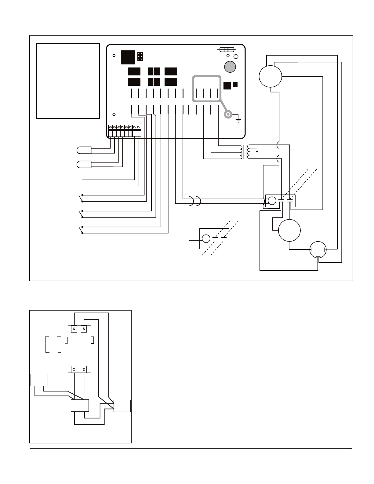
Figure 7 - PRO1100e TCE & PRO1300 TCE wiring diagram
Water Sensor
Defrost Sensor
High Pressure Switch
Closed = OK
Opened = High Pressure
Low Pressure Switch
Closed = OK
Opened = Low Pressure
Flow Switch
Closed = Flow
Opened = No Flow
MY-TECH PH-111A
Brown
Brown & White
SPR1
SPR2
REVR
JANDY
HP
LP FLO
COMP
PUMP
12 ~8 ~12
AC F1 F2 F3
WS
DS
AS
P/S
Black
Black
Blue
Orange
Blue
Orange
Blue
Gray
12 VAC
Blue
Red
Blue
12 / 24 VAC Transformer
Black
Yellow
Yellow
24
Vac
COMPRESSOR
R
S
C
24 VAC
Compressor
Contactor Coil
Run Cap
L1
L2
Black
Black
Yellow
Black
Black
Red
H
C
F
Red
Blue
FAN
Black
Black
White
24 VAC
pool pump
contactor coil
L4
Pool Pump
L3
PRO1300, PRO1100e, PRO1300h/c, PRO1100,
PRO1300h/c TCE, PRO1300 TCE, PRO1100e TCE
Phone: (877)-278-2797
7
www.aquaprosystems.com
To Remote System
(If Applicable)
•
This unit is prepared at the factory with
the “FIL” mode set to the “off” position.
You will need to set the heat pump’s
hours of run time in the “FIL” mode to
“2” hours. See “activating and setting
system run time” below to set the run
time. Leave your time clock set to the
desired pump and filter operation time.
This will enable the heat pump and filter
system to run the desired hours of the
day and also provide the benefit of
checking if heat is needed every 4 hours.
It will do this by running the pump and
filter system for 15 minutes. If heat is
needed, it will continue to run until the
pool has reached the set temperature. If
no heat is needed, the system will turn
off and continue checking for heat every
4 hours. This provides a couple of added
benefits. Pools will lose most of their
heat at night if left uncovered, however,
since the unit is checking for and adding
heat when needed, it prevents long
recovery times when compared to nonTCO units. The other benefit is that some
states and electric utility companies offer
a discount for off-peak usage of
electricity. Please contact your electricity
provider if you have questions.
Activating and Setting System Run
Time – TCO Operation
•
To set the run time of the system,
push the “SET” button repeatedly
until “FIL” displays. Then using the
“up” and “down” arrows, set the
hours to “2”. The range of hours is
“off” to 2, 3, 4,… up to 23 hours to
“on”. By selecting “2” the heat pump
will run every 4 hours for 20 minutes,
checking if heat is needed. The unit
leaves the factory with the “FIL”
mode set to “OFF”.
Time Clock Override
(TCO) Operation (cont.)
INSIDE
HEAT
PUMP
CONTACTOR
FOR THE
TIME CLOCK
OVERRIDE
TIME
CLOCK
FILTER
PUMP
BREAKER
Figure 8 - TCO wiring diagram
(optional)
PRO1100e
TCE
and
PRO1300
TCE
INSIDE
HEAT
PUMP
T2 T1
CONTACTOR
FOR THE
TIME
CLOCK
OVERRIDE
L3 L4
BREAKER
TIME
CLOCK
FILTER
PUMP
 Loading...