


Pool and Spa
Heat Pump
Owner’s Manual
and
Installation Guide
PN: LTP0009 01/12/04
Models:
T65
T115
T135
(Also Applies to All C115 Models)
ATTENTION INSTALLER:
THIS DOCUMENT IS PURCHASER’S PROPERTY AND IS TO REMAIN WITH THE HEAT PUMP OWNER
1/7/041

1-800-786-7751 |
NOTES |
|
___________________________________________________________________________________
__________________________________________________________________________________
___________________________________________________________________________________
_________________________________________________________________________________
_________________________________________________________________________________
_________________________________________________________________________________
___________________________________________________________________________________
__________________________________________________________________________________
___________________________________________________________________________________
_________________________________________________________________________________
__________________________________________________________________________________
________________________________________________________________________________________
___________________________________________________________________________________
____________________________________________________________________________________
_________________________________________________________________________________
__________________________________________________________________________________
_________________________________________________________________________________
__________________________________________________________________________________
__________________________________________________________________________________
2
TABLE OF CONTENTS
WELCOME TO THE TEAM ------------------------------------------------------------------ |
4 |
IMPORTANT FEATURES OFYOUR NEW HEAT PUMP -------------------------------- |
5 |
SAFETYINFORMATION --------------------------------------------------------------------- |
6 |
QUICK START & STOP ----------------------------------------------------------------------- |
8 |
PHYSICAL CHARACTERISTICS & PERFORMANCE ----------------------------------- |
9 |
Dimensional Information - TropiCal Models T65 and T115 --------------------------- |
9 |
Dimensional Information - TropiCal Model T135 -------------------------------------- |
10 |
TropiCal: Table of Specifications--------------------------------------------------------- |
11 |
Refrigerant Circuit Performance Charts ------------------------------------------------- |
11 |
Guide: Troubleshooting Refrigerant Circuit Problems --------------------------------- |
13 |
INSTALLATION -------------------------------------------------------------------------------- |
14 |
Placement of Heater ------------------------------------------------------------------------- |
14 |
Plumbing Requirements--------------------------------------------------------------------- |
16 |
Electrical Requirements -------------------------------------------------------------------- |
18 |
START-UP& OPERATION ------------------------------------------------------------------- |
20 |
Overview of Controls------------------------------------------------------------------------ |
21 |
Initial Start-up and Basic Operation ------------------------------------------------------- |
21 |
Heating Tips ---------------------------------------------------------------------------------- |
22 |
Calculating Initial Heating Time ----------------------------------------------------------- |
23 |
MAINTENANCE ------------------------------------------------------------------------------- |
24 |
Planned Maintenance ----------------------------------------------------------------------- |
25 |
General Maintenance ----------------------------------------------------------------------- |
25 |
Maintaining Proper Water Flow ----------------------------------------------------------- |
26 |
Maintaining Proper Clearances Around Heater ------------------------------------------ |
27 |
SEASONAL USE & SHUT DOWN ---------------------------------------------------------- |
27 |
During the Swim Season -------------------------------------------------------------------- |
27 |
Freeze protection / Extended Shut Downs ------------------------------------------------ |
27 |
Winterizing (Hard Freeze Conditions) --------------------------------------------------- |
27 |
TROUBLESHOOTING ------------------------------------------------------------------------ |
29 |
Common Troubleshooting Issues ---------------------------------------------------------- |
29 |
Troubleshooting Flow Charts --------------------------------------------------------------- |
30 |
REPLACEMENTPARTS --------------------------------------------------------------------- |
34 |
CONTACTINGTHEFACTORY -------------------------------------------------------------- |
35 |
3

Welcome
Tto the
eam
Dear Owner:
Congratulations on your wise decision to make an AquaCal heat pump part of your home. Since 1981, AquaCal has maintained the worldwide lead in the manufacture of swimming pool & spa heat pumps. Your new heat pump is not only a
great investment, but also the most cost effective method available for heating pools and spas. For example, as a means to heat pool or spa water, your heat pump is up to 400% more efficient than gas, and, when compared to electric resistance heat, your heat pump is nearly 600% more effective. You can rest assured that your new heat pump is of the highest quality and efficiency, and is designed and built to provide years of trouble-free operation.
Moreover, should you decide you would like AquaCal to provide regular inspection and maintenance for your heat pump—which we do recommend—you will find AquaCal has the largest and best-qualified service staff in the pool & spa heat pump industry.
4

IMPORTANT FEATURES OF YOUR NEW HEAT PUMP
ThermoLink Heat Exchanger:
The heart of your heat pump is the patented ThermoLink heat exchanger. The primary cause of premature heat pump demise is the failure of the heat exchanger. Ordinary heat exchangers are made from a cupronickel alloy. This cupronickel material is susceptible to attack
from the sanitizers used in pools and spas, and from other related water chemistry conditions. Once the heat exchanger fails, the heat pump is ruined. The ThermoLink heat exchanger tube is made from titanium, and is virtually impervious to water-chemistry damage.
Electronic
Controller:
State-of-the-art, solid-state electronic controller, maintains water temperature within 1ºF of set point. Controller also permits user to predefine different Pool and Spa water temperature set points.
Corrosion-Resistant Cabinet:
Hybrid design utilizes the best features of finished aluminum and resilient ABS plastic. The base, being ABS material, will never rust or corrode. The remainder of the cabinet is constructed from sturdy, marine-grade, powder-coated aluminum.
PLEASE SPEND A FEW MINUTES READING FURTHER TO BECOME FAMILIAR WITH ALL THE FEATURES, THE SAFE OPERATION, AND THE CARE OF YOUR NEW HEAT PUMP.
5

SAFETY INFORMATION
Used and maintained properly, your heat pump will provide year-upon-year of safe and economical service.
However, as with any mechanical or electrical device, to get the most from your heat pump–while insuring personal safety for you and others–certain operational and maintenance factors must be observed.
Likewise, excepting a few minor owner-capable maintenance items (explained later in this manual), repair and service of your heat pump must be performed only by experienced service personnel. Should you, the owner, suspect your heat pump is not performing properly, by referring to the section in this manual entitled: "Troubleshooting", you will be able to determine if a call for service is required. Your installer can be one source of service, or AquaCal Customer Support personnel stand ready to assist you at: (800) 786-7751. For questions
concerning installation, modifications, operation, service and upkeep, please contact your installer or AquaCal Customer Support. Warranties may be voided if the heater has been used, maintained, or repaired improperly.
In addition to possible voiding of warranties: unapproved installation methods, nonstandard modifications, poor or incorrect maintenance, service by unqualified personnel, or improper use of this unit, may result in personal injury
and/or property damage. For personal safety and to avoid damage to equipment, it is important that safety instructions displayed on the heat pump, and within this manual, are read, understood, and followed.
Throughout this manual the following two safety signals are placed where particular care is required. Please note "WARNING" relates to personal safety, while "CAUTION" signals promote avoiding damage to equipment.
WARNING ! Failure to heed the following may result in permanent injury or death.
This “Warning” symbol appears in this manual where special attention is required for personal safety.
Specific instructions will appear in this box.
CAUTION ! |
Failure to heed the following may result in damage to equipment. |
|
This “Caution” symbol appears in this manual where special care is required to avoid equipment damage.
Specific instructions will appear in this box.
|
Water Temperature Safety |
||
|
|
|
|
WARNING ! |
|
death. |
|
|
|
Failure to heed the following may result in permanent injury or |
|
|
|
|
|
Prolonged immersion in water warmer than normal body temperature may cause a condition known as HYPERTHERMIA. The symptoms of hyperthermia include: unawareness of impending hazard, failure to perceive heat, failure to recognize the need to exit the spa and unconsciousness. The use of alcohol, drugs, or medication can greatly increase the risk of fatal hyperthermia. In addition, persons having an adverse medical history, or pregnant women should consult a physician before using a hot tub or spa. Children and the extreme elderly should be supervised by a responsible adult.
6

Heater NOT Repairable by Owner
WARNING ! Failure to heed the following may result in permanent injury or death.
Heat pumps contain no owner-repairable components. Repairs must not be attempted by untrained and/or unqualified individuals. If service is deemed necessary, contact installing dealer orAquaCal Customer Support at (800) 786-7751.
Refrigerant Circuit Service Only by
Qualified, EPA Certified Technician
WARNING ! Failure to heed the following may result in permanent injury or death.
Heater contains refrigerant under high pressure. Repairs to the refrigerant circuit must not be attempted by untrained and/or unqualified individuals. Service must be performed only by qualified HVAC technicians. Recover refrigerant to relieve pressure before opening system.
|
Water Chemistry Safety |
|
|
|
|
WARNING ! |
|
death. |
|
|
Failure to heed the following may result in permanent injury or |
|
|
|
Improper water chemistry can present a serious health hazard. To avoid possible hazards, maintain Pool-Spa water per standards below.
CAUTION ! |
Failure to heed the following can result in damage to equipment. |
|
While your heat pump’s titanium-based heat exchanger provides nearly impervious protection against poor water chemistry, improper water chemistry may cause expensive damage to pump, filter, pool shell, etc. To avoid equipment damage, maintain Pool-Spa water per standards below.
RECOMMENDED WATER CHEMISTRY STANDARDS
Chlorine . . . . . . . . . . . . . . . |
: |
1.0 – 3.0 ppm in pools, 1.5 – 3.0 ppm in spas |
Bromine . . . . . . . . . . . . . . . |
: |
2.0 – 4.0 ppm in pools, 3.0 – 5.0 ppm in spas |
pH . . . . . . . . . . . . . . . . . . . |
: |
7.4 – 7.6 ppm in pools, 7.2 – 7.8 ppm in spas |
Total Alkalinity . . . . . . . . . . |
: |
80 – 140 ppm in pools, 80 – 120 ppm in spas |
Calcium Hardness . . . . . . . . |
: |
200 – 400 ppm in pools and spas |
Total Dissolved Solids . . . . . |
: |
1,000 – 2,000 ppm in pools, |
|
|
1,500 ppm above start-up TDS in spas |
7
QUICK START & STOP
This brief information is provided as an aide to installers, service personnel, and owners. The intent of this section is to provide rapid access to (only) very basic operational information. Individuals who will be routinely using, installing, maintaining and servicing this heat pump are strongly encouraged to read this entire manual. If uncertain about any instructions given herein, AquaCal Customer Support (800-786-7751) should
be contacted for additional information.
Start Up
1.Set pump controls to allow for temporary, continuous operation.
2.With pump OFF, position water valves to heat the POOL or SPA.
3.Rotate both thermostats counterclockwise to lowest temperature setting.
4.Depending on valve settings (per #2, above), position the POOL/OFF/SPA toggle switch to point at either the POOL or SPA thermostat knob.
5.Ensure power is supplied to the heater, then start the water pump; the POWER and FLOW lights should now both be lit. Permit the water pump to operate for five (5) minutes before proceeding
How to Operate the Controls - Pool or Spa
1.Turn the selected pool or spa thermostat dial clockwise to its highest setting.
2.The heat pump will start and begin to heat the pool or spa.
NOTE: The heat pump has a time delay so if it shuts down for any reason, it will not restart for approximately five (5) minutes.
3.The typical spa may take several hours to initially heat up, while a pool may take several days. Heating time will depend on the volume of water, water temperature, and the climatic conditions at the time of start-up. (Also see Calculating Initial Heating Time.)
4.When the pool or spa reaches the desired temperature, slowly rotate the thermostat knob counterclockwise until the heat pump (just) stops. The thermostat is now set to automatically maintain this temperature.
Time Clock Programming
Once the heat pump has brought the pool or spa up to temperature, it will be necessary to reset the pump controls. Be sure to allow enough running time for the heat pump to replace lost heat. This time will vary depending upon the time of year. Colder months require longer running times—usually eight to twelve hours.
Manual Switching From Pool to Spa
NOTE: It is best to stop the pump while repositioning valves.
1.Open spa valves and close pool valves.
2.With the spa filter pump running for at least five minutes, move the POOL/OFF/SPA toggle switch from the Pool Setting to the Spa Setting.
3.Turn the Spa thermostat clockwise until it stops (104 F).
4.The typical spa may take several hours to initially heat up. Heating time all depends on the volume of water, water temperature and the climatic conditions at the time of start-up.
5.When the spa reaches the desired temperature (104 F is maximum), slowly rotate the thermostat knob counterclockwise until the heat pump (just) stops. The spa thermostat is now set to automatically maintain this temperature any time the spa thermostat has been selected.
To Stop the Heat Pump
The unit can be stopped by switching off the electrical supply or by setting the desired temperature lower than the actual water temperature.
8

PHYSICAL CHARACTERISTICS
& PERFORMANCE
Dimensional Information - TropiCal Models
T65 and T115
A
NOTES:
1. ALL DIMENSIONS IN INCHES
2. MIN. CLEARANCE 24" FROM AIR COIL
B |
|
|
DATA PLATE |
|
|
INFORMATION |
|
|
CONTROL BOX |
COMPRESSOR |
|
ACCESS PANEL |
||
ACCESS PANEL |
||
|
||
|
C |
|
B |
A |
F |
G |
|
|
E |
|
D |
|
AIR COIL |
REAR VIEW
POWER |
|
|
OPTIONS |
|
|
BONDING |
|
|
LUG |
|
K |
|
J |
|
|
|
|
|
H |
|
9
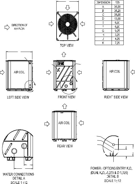
Dimensional Information - TropiCal
Model T135
A
NOTES:
1. ALL DIMENSIONS IN INCHES
2. MIN. CLEARANCE 24" FROM AIR COIL
B
DATA PLATE
INFORMATION
B |
E |
D |
CONTROL BOX |
COMPRESSOR |
ACCESS PANEL |
ACCESS PANEL |
|
A |
POWER
OPTIONS
BONDING LUG


 J K H
J K H

10
TropiCal: Table of Specifications
MODELS: |
|
T65”X”-A |
|
T65”X”-B |
|
T115 “X”-A |
|
T115 “X”-B |
|
T135 “X”-A |
|
T135 “X”-B |
|
|
|
|
|
|
|
||||||||
BTU - 80%RH |
|
|
|
|
|
|
|
|
|
|
|
|
|
|
|
|
|
|
|
|
|
||||||
Air ºF / Air ºF… |
80/50 |
55000/37000 |
55000/37000 |
104,000/70,000 |
104,000/70,000 |
126,000/82000 |
126,000/82000 |
||||||
|
|
|
|
|
|
|
|
||||||
COP |
|
4.8/3.7 |
4.8/3.7 |
4.3/3.2 |
4.3/3.2 |
5.7/4.0 |
5.7/4.0 |
||||||
|
|
|
|
|
|
|
|
|
|
|
|
|
|
|
|
|
|
|
|
|
|
|
|
|
|
|
|
BTU - 63% RH |
|
|
|
|
|
|
|
|
|
|
|
|
|
|
|
|
|
|
|
|
|
||||||
Air ºF / Air ºF… |
80/50 |
51000/34000 |
51000/34000 |
97,000/65,000 |
97,000/65,000 |
119000/77000 |
119000/77000 |
||||||
|
|
|
|
|
|
|
|
||||||
COP |
|
4.5/3.6 |
4.5/3.6 |
4/3.1 |
4/3.1 |
5.4/3.8 |
5.4/3.8 |
||||||
|
|
|
|
|
|
|
|||||||
|
|
|
|
|
|
|
|||||||
Kilowatt Input (80% RH) |
3.4 |
3.4 |
7.1 |
7.1 |
6.5 |
6.5 |
|||||||
|
|
|
|
|
|
|
|||||||
|
|
|
|
|
|
|
|||||||
Voltage/Hz/Phase |
208-230/60/1 |
208-230/60/3 |
208-230/60/1 |
208-230/60/3 |
208-230/60/1 |
208-230/60/3 |
|||||||
Min. Circuit Ampacity |
20.01 |
14.04 |
40.56 |
26.14 |
37.36 |
30.14 |
|||||||
Recommended Fuse Size |
20 |
15.00 |
40 |
30 |
40 |
35 |
|||||||
|
|
|
|
|
|
|
|||||||
Max. Fuse or Breaker Size |
30 |
20.00 |
70 |
40 |
60 |
50 |
|||||||
|
|
|
|
|
|
|
|||||||
|
|
|
|
|
|
|
|||||||
Min-Max Water Flow (gpm) |
20-70 |
20-70 |
20-70 |
20-70 |
20-70 |
20-70 |
|||||||
|
|
|
|
|
|
|
|||||||
|
|
|
|
|
|
|
|||||||
Shipping weight (lbs) |
250 |
250 |
270 |
270 |
300 |
300 |
|||||||
|
|
|
|
|
|
|
|
|
|
|
|
|
|
Shipping Size (l x w x h) |
|
36" X 30" X 35" |
|
36" X 30" X 35" |
|
36" X 30" X 35" |
|
36" X 30" X 35" |
|
36"X30"X42 |
|
36"X30"X42 |
|
|
|
|
|
|
|
|
|||||||
|
|
|
|
|
|
|
|||||||
Uncrated Weight (lbs) |
223 |
223 |
243 |
243 |
273 |
273 |
|||||||
|
|
|
|
|
|
|
|
|
|
|
|
|
|
Refrigerant Circuit Performance Charts
Use of ChartsInformation for the Technician:
The charts are intended for use by trained and qualified air-conditioning and refrigeration technicians only. The charts are compiled specifically for evaluation and diagnostic purposes, and are NOT designed for use as charging charts. To apply the chart data to actual conditions: gather the operating pressures, suction tube superheat & liquid line subcooling values, water temperature change through the heater, and the total unit amps. Locate a chart that most closely represents current actual conditions. Readings obtained that differ from the charts in excess of 10% (+ or -), may indicate a problem within the mechanical refrigeration system. Reference: Troubleshooting Refrigerant Circuit Problems, following the charts. Some interpolation between charts will be necessary should actual conditions not align reasonably well with the charts. Should refrigerant circuit readings appear normal, but not the Water DT value, the likely cause will be water flow above or below 45 GPM. (TropiCal refrigerant circuits will perform acceptably with condenser water flow between 20 to 70 GPM.)
Performance Charts Follow
11
 Loading...