

AquaCal LTP0114 User Manual

®
WATER CHILLER
®
AquaCal
Installation Manual
For additional product manuals and operation / installation procedures, please visit www.AquaCal.com
Important
Read this document before operating / installing this product
LTP0114 REV 2.03- (project rel 7.02)


Table of Contents
Contacting AquaCalAutoPilot, Inc. 1
Safety Instructions 1
1 - Installation 3
1.1 Positioning Equipment 4
1.2 Clearances 5
1.3 Dimensions 6
1.4 Plumbing 7
1.4.a Plumbing Requirements 7
1.4.b Plumbing Diagrams 7
1.4.c Water Connections to Heat Pump 10
1.4.d In-Line Chlorine Feeders 11
1.4.e Water Flow Rates 11
1.4.f Adjusting Water Flow Using ΔT (Delta-T) 13
1.4.g Maintaining Ability to Winterize 15
1.4.h Adjusting Water Pressure Switch 15
1.5 Electrical 16
1.5.a Electrical Requirements 16
1.5.b Incoming Power Access Holes 19
1.5.c Access Panels 20
1.5.d Verifying Transformer Setting 21
1.5.e Three-Phase Adjustment 22
1.5.f Schematic Location 22
1.6 External Equipment 23
1.6.a Connecting a Call Flex 23
1.6.b Connecting a Chlorinator 25
1.6.c Connecting External Controllers to Heat Pump 26
c.1 Connecting Smart Bus Controllers 27
c.2 Connecting Two-wire Controllers (with internal thermostat) 31
1.6.d Connecting Gas Backup Heater to Heat Pump 33
1.6.e Connecting Multiple Heat Pumps (Master / Slaved) 39
1.6.f Connecting a Pool/Spa Switching Relay 44
1.7 Program Heat Pump for the Customer 47
1.7.a Setting Date and Time 47
1.7.b Setting Time and Date Format 48
1.7.c Selecting Celsius or Fahrenheit 51
1.7.d Configure Variable Speed Compressors 52
1.7.e Setting Entry Code Option 57
1.7.f Using Entry Code to Access Heat Pump 59
1.7.g Resetting Factory Defaults 59
1.8 Cleaning Equipment After Installation 61
2 - Troubleshooting 63
2.1 Fault Codes 64
2.2 Issues and Resolutions 70
3 - Appendix 77
3.1 Factory Defaults 77
3.2 Identifying Model Specifications 78
i

3.3 Weights 80
3.4 Heating Recommendations 81
3.5 Cooling Recommendations 81
3.6 Available Accessories 81
ii
Contacting AquaCalAutoPilot, Inc.
For further assistance, please contact the distributor or installer of this product.
If unavailable, please contact AquaCal®for a partner in your area. To better assist you, please have the heat
pump model and serial number available.
l
See "Identifying Model Specifications" on page78.
Product Information:
Website www.AquaCal.com
Phone (1) 727-823-5642
Hours 8-5 pm, Eastern M-F
Service Information:
Website www.AquaCal.com/request-heat-pump-service/
SAFETY INSTRUCTIONS
l For personal safety, and to avoid damage to equipment, follow all safety instructions displayed on the equipment
and within this manual. Repair and service of heat pump must be performed by an authorized service center.
l Warranties may be voided if the equipment has been improperly installed, maintained or serviced.
l
If service is deemed necessary, please contact AquaCal. See "Contacting AquaCalAutoPilot, Inc." above.
SAFETY SIGNALS
Throughout this document, safety signals have been placed where particular attention is
required.
Failure to heed the following will result in injury or death.
DANGER
WARNING
Failure to heed the following may result in injury or death.
NOTICE
When installing and using your heat pump basic safety precautions must always be followed, including the
following:
Failure to heed the following will result in injury or death.
Failure to heed the following may result in damage to
equipment.
DANGER
l The heat pump utilizes high voltage and rotating equipment. Use caution when servicing.
l RISK OF ELECTRICAL SHOCK FROM ENERGY STORED IN CAPACITORS - MODELS EQUIPPED
WITH VARIABLE FREQUENCY COMPRESSOR DRIVES STORE ELECTRICITY EVEN AFTER THE
POWER HAS BEEN DEACTIVATED AT THE POWER BREAKER. Wait for 2 minutes after the shut down
of equipment before servicing.
l Follow all National Electric Codes (NEC) and/or State and Local guidelines.
Page - 1

WARNING
Failure to heed the following may result in injury or death.
l Installation and repairs must be performed by a qualified technician.
l The heat pump contains refrigerant under pressure. Repairs to the refrigerant circuit must not be attempted by
untrained and/or unqualified individuals. Service must be performed only by qualified HVAC technicians. Recover
refrigerant before opening the system.
l Improper water chemistry can present a serious health hazard. To avoid possible hazards, maintain pool/spa water
per standards as detailed in the product's operation manual.
l Prolonged immersion in water warmer than normal body temperature may cause a condition known as
Hyperthermia. The symptoms of Hyperthermia include unawareness of impending hazard, failure to perceive heat,
failure to recognize the need to exit the spa, and unconsciousness. The use of alcohol, drugs, or medication can
greatly increase the risk of fatal Hyperthermia. People having an adverse medical history, or pregnant women
should consult a physician before using a hot tub or spa. Children and the elderly should be supervised by a
responsible adult.
l Prolonged immersion in water colder than normal body temperature may cause a condition known as Hypothermia.
The symptoms of Hypothermia include shivering (although as hypothermia worsens, shivering stops), clumsiness
or lack of coordination, slurred speech or mumbling, confusion and poor decision-making, drowsiness or low
energy, lack of concern about personal welfare, progressive loss of consciousness, weak pulse and slow or shallow
breathing. Persons having an adverse medical history, or pregnant women, should consult a physician before
immersing in a cold body of water. Children and the elderly should be supervised by a responsible adult.
NOTICE
l Maintain proper water chemistry to avoid damage to the pump, filter, pool shell, etc.
l Water flow exceeding the maximum flow rate requires a bypass. Damage due to excessive water flow will void the
Failure to heed the following may result in damage to equipment.
warranty.
SAVE THESE INSTRUCTIONS
Page - 2
1 - Installation
WARNING
Failure to heed the following may result in injury or death.
l Installation of this equipment by anyone other than a qualified installer can result in a safety hazard.
l The information contained throughout the "Installation" section is intended for use by qualified installation
technicians familiar with the swimming Pool/Spa safety standards.
NOTICE
l Failure to protect equipment against corrosive conditions will adversely affect the life of the equipment and will
void equipment warranty.
Failure to heed the following may result in damage to equipment.
IN THIS SECTION:
1.1 Positioning Equipment 4
1.2 Clearances 5
1.3 Dimensions 6
1.4 Plumbing 7
1.4.a Plumbing Requirements 7
1.4.b Plumbing Diagrams 7
1.4.c Water Connections to Heat Pump 10
1.4.d In-Line Chlorine Feeders 11
1.4.e Water Flow Rates 11
1.4.f Adjusting Water Flow Using ΔT (Delta-T) 13
1.4.g Maintaining Ability to Winterize 15
1.4.h Adjusting Water Pressure Switch 15
1.5 Electrical 16
1.5.a Electrical Requirements 16
1.5.b Incoming Power Access Holes 19
1.5.c Access Panels 20
1.5.d Verifying Transformer Setting 21
1.5.e Three-Phase Adjustment 22
1.5.f Schematic Location 22
1.6 External Equipment 23
1.6.a Connecting a Call Flex 23
1.6.b Connecting a Chlorinator 25
1.6.c Connecting External Controllers to Heat Pump 26
1.6.d Connecting Gas Backup Heater to Heat Pump 33
1.6.e Connecting Multiple Heat Pumps (Master / Slaved) 39
1.6.f Connecting a Pool/Spa Switching Relay 44
1.7 Program Heat Pump for the Customer 47
1.7.a Setting Date and Time 47
1.7.b Setting Time and Date Format 48
1.7.c Selecting Celsius or Fahrenheit 51
1.7.d Configure Variable Speed Compressors 52
1.7.e Setting Entry Code Option 57
1.7.f Using Entry Code to Access Heat Pump 59
1.7.g Resetting Factory Defaults 59
1.8 Cleaning Equipment After Installation 61
1 - Installation
Page - 3

1.1 Positioning Equipment
NOTICE
l Do not install equipment inside of a building.
Failure to heed the following may result in damage to equipment.
Outdoor Use Only
Do not install equipment inside of a room or building.
l Heat Pumps require unobstructed airflow for proper operation. Heat Pumps should never be installed indoors or in
a location where airflow is restricted.
l
See "Clearances" on the facing page.
Controlling Irrigation and Rainwater Runoff
l Irrigation water may damage heat pump components. Direct irrigation water away from the heat pump.
l The heat pump will withstand normal rainfall. Do not allow a roof slope to direct rainwater onto the heat pump.
Have a gutter installed on the roof edge to direct this water away from the heat pump. Or install the heat pump in
another location.
Planning for Condensation
The heat pump can produce a large amount of condensation. The amount of water depends on air temperature
and humidity.
l Install the heat pump with enough height to allow for water drainage.
l Plan for water drainage as needed.
n
See "Condensation Drain Kit (# STK0202)" on page81.
Mounting Pad Requirements
l
The heat pump's base must be installed on a flat and level surface that completely supports the entire base.
l Build the heat pump pad out of concrete or other code-approved material.
1 - Installation
l
Confirm the pad can support the weight of the heat pump. See "Weights" on page80.
l Elevate the pad enough to allow for drainage.
l Make sure the pad is flat and level.
l
Have the pad support the entire heat pump base in all directions.
l Do not install the heat pump on soil or grass.
l Do not allow the heat pump base to touch the building's foundation.
l Do not place the heat pump directly on a concrete floor. This can cause noise to be transmitted to an occupied
space. If necessary install vibration dampers between the heat pump base and floor.
l Equipment pad must meet all requirements of authorities having code-related jurisdiction.
Anchoring to Pad
l Follow all applicable local, state, and national requirements regarding wind load anchoring.
l The shipping brackets used to secure the heat pump to the pallet are approved mounting (hurricane) brackets.
They should be used to anchor the heat pump to the pad.
l
If needed, contact AquaCal®to obtain anchoring kit information. Please have the heat pump model number and
serial number when requesting support. See "Identifying Model Specifications" on page78.
Page - 4
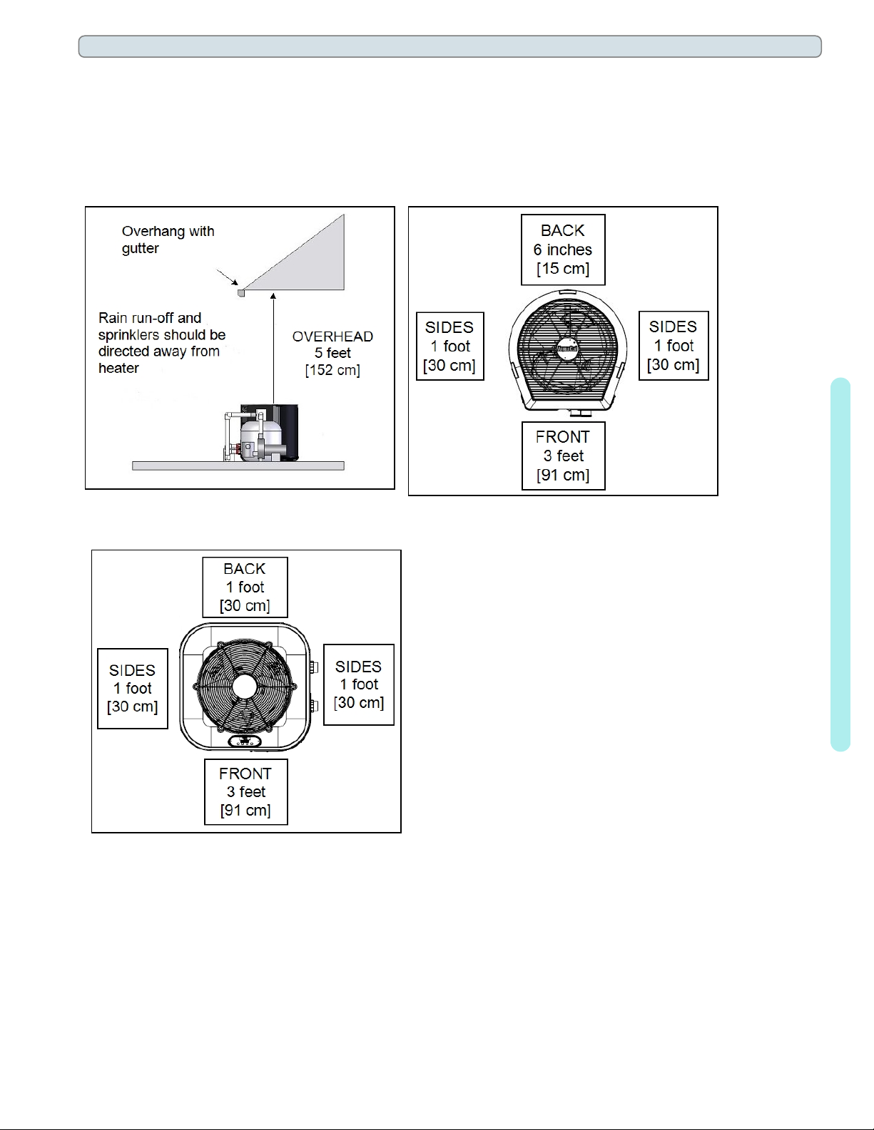
1.2 Clearances
l Proper air circulation is required for the heat pump to operate efficiently. The following diagrams show the
minimum clearances required for the proper operation of the heat pump.
l Avoid storing chemical containers near the heat pump. The chemicals can cause equipment damage.
l Avoid placing objects near or on top of the heat pump. This includes shrubbery and lawn furniture. These objects
will reduce performance and efficiency and hinder maintenance access.
(Overhead Clearance) (Top View)
(Top View)
TropiCal®T170
1 - Installation
Page - 5
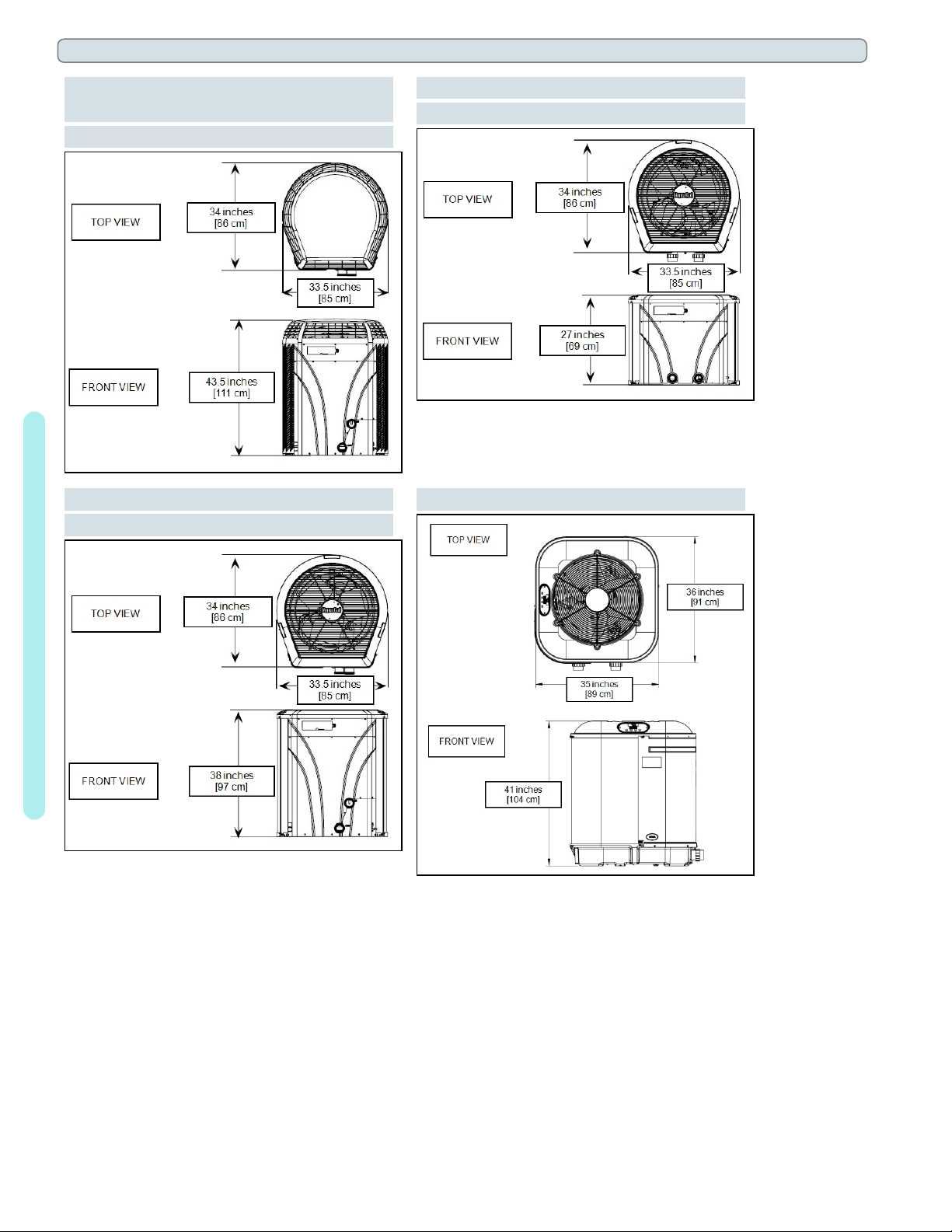
1.3 Dimensions
(HeatWave SuperQuiet®SQ120R,
SQ125, SQ145, SQ166R and SQ225)
(TropiCool®TC1500)
(TropiCal®T090, T115 and T135)
(TropiCool®TC1000)
(TropiCal®T035, T055 and T075)
(TropiCool®TC500)
(TropiCal®T170)
1 - Installation
Page - 6
1.4 Plumbing
1.4.a Plumbing Requirements
NOTICE
l Do not use glue on the threaded portion of the equipment’s unions. A glued-in-place union will prevent the
Failure to heed the following may result in damage to equipment.
equipment from being properly winterized.
l The heat pump must receive water flow within the specified minimum ranges under worst-case conditions such as
a fouled water filter.
l Failure to provide clean filtered water to the heat pump can void the product warranty.
l Water flow exceeding maximum flow rates will negatively affect the total pool filtration performance and may
damage the heat pump. This will not be covered under the equipment warranty. See "Water Flow Rates" on
page11.
l Install a bypass valve whenever water-flow may exceed the maximum rating.
l See "Bypass Valve Kit (# STK0135)" on page81.
l
For additional guidance testing water flow rates, please contact AquaCal®.
l
A safety-enhancing "Over Temperature Alarm"kit is strongly recommended for all spa applications. See "Over
Temperature Alarm Kit" on page82.
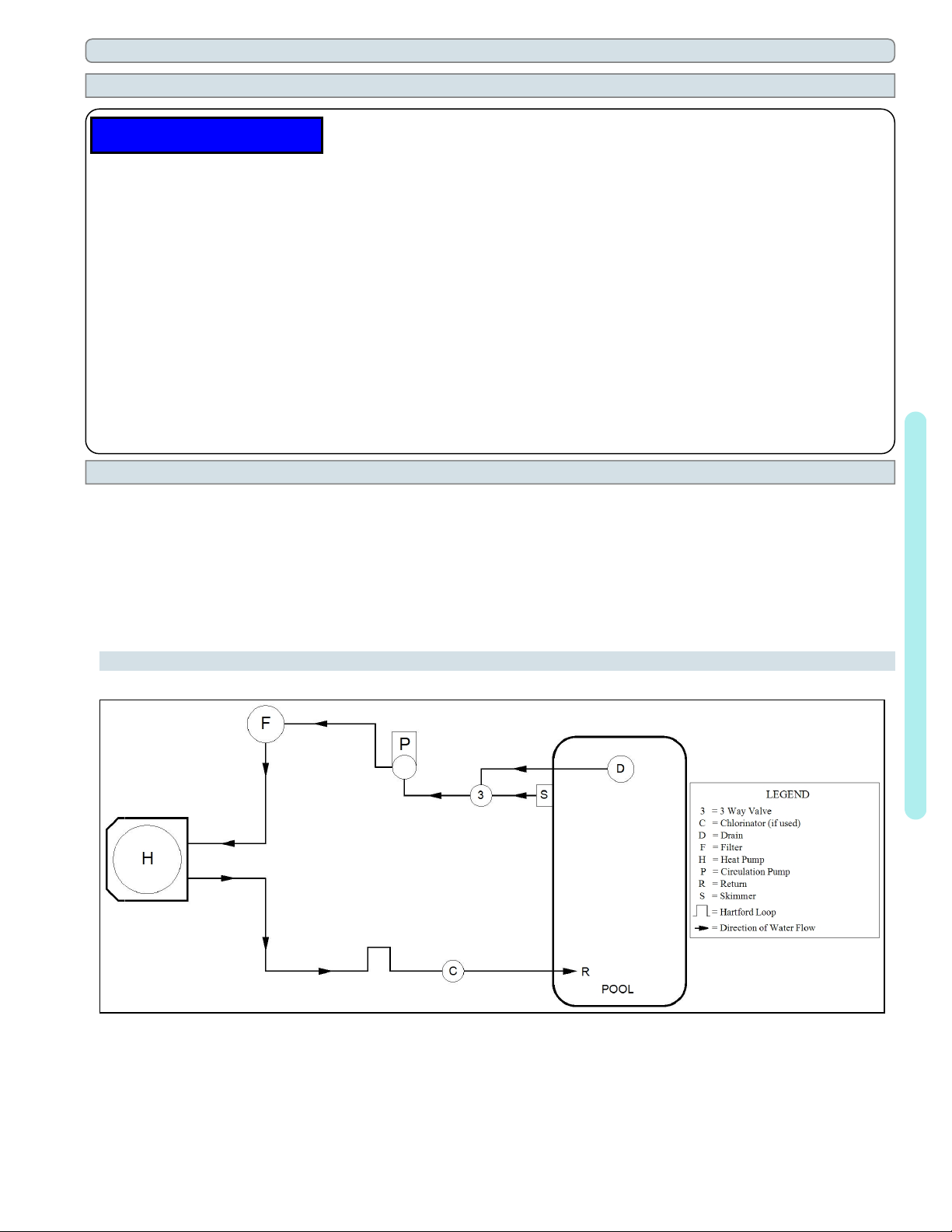
1.4.b Plumbing Diagrams
Plumbing diagrams are provided in this section as a planning guide to the sequence of equipment, valves, and
fittings.
l The basic plumbing configurations for typical installations are shown.
l
If the installation does not closely follow any of the supplied plumbing diagrams, AquaCal®Technical Support is
available for installation advice and guidance.
l Confirm water provided to the heat pump is clean and filtered.
1 - Installation
Heat Pump with water flows equal or less than the maximum listed flow rate
See "Water Flow Rates" on page11.
Page - 7
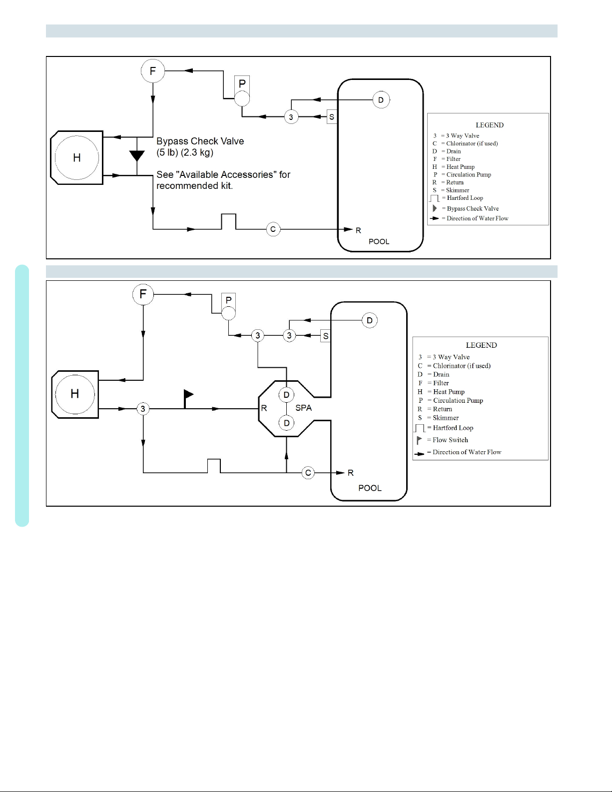
Heat Pump with water flows greater than the maximum listed flow rate
See "Water Flow Rates" on page11.
Heat Pump with Spillover Spa (One filter Pump)
1 - Installation
Page - 8
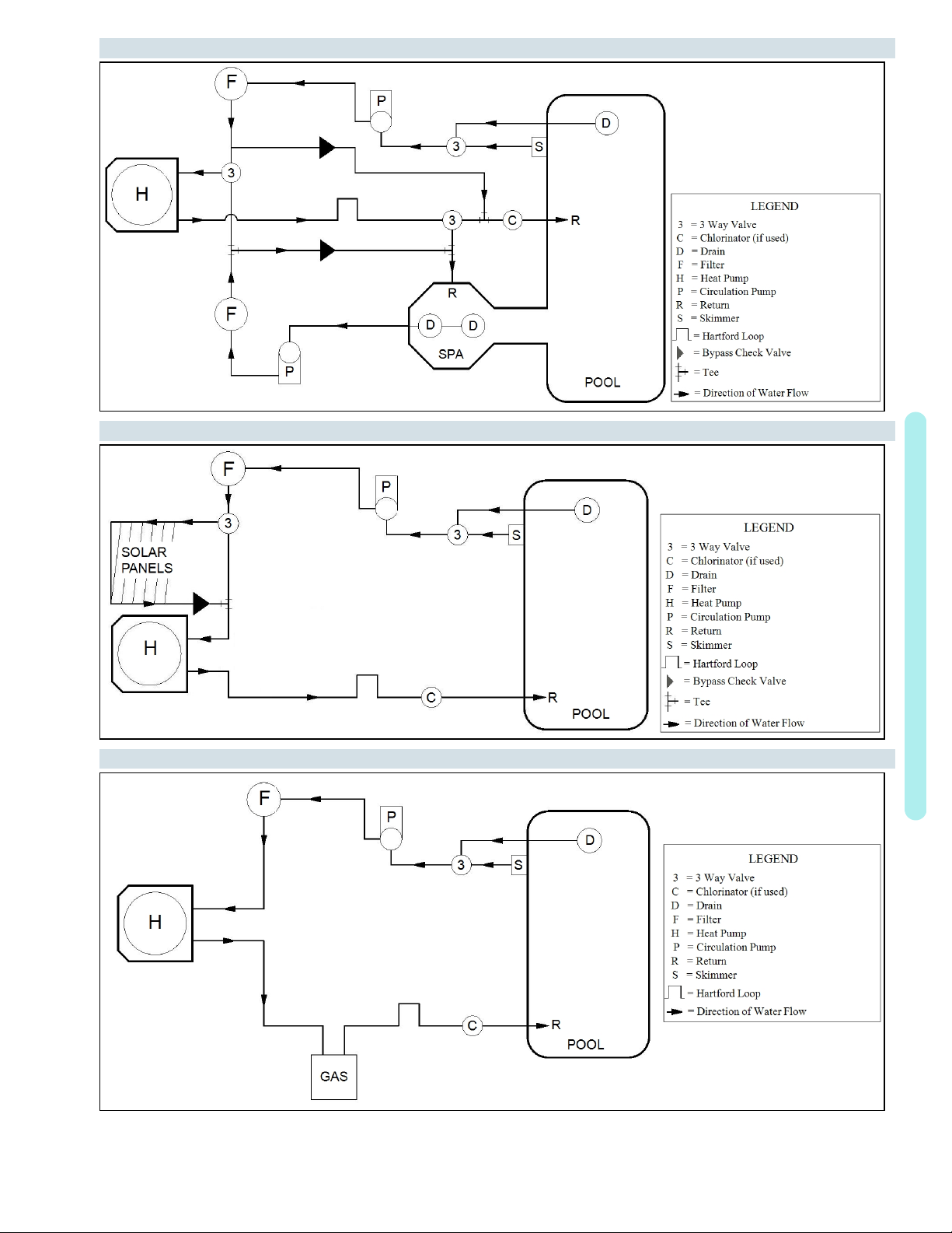
Heat Pump with Spillover Spa (Two filter Pumps)
Heat Pump with Solar Panels in Plumbing Circuit
Heat Pump with Gas Heater backup
1 - Installation
Page - 9
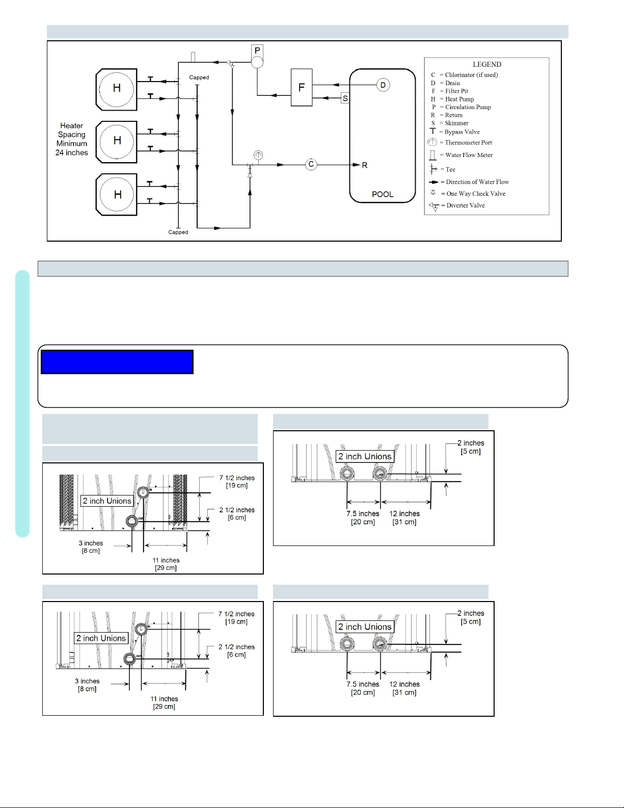
Multiple Air Source Heat Pumps
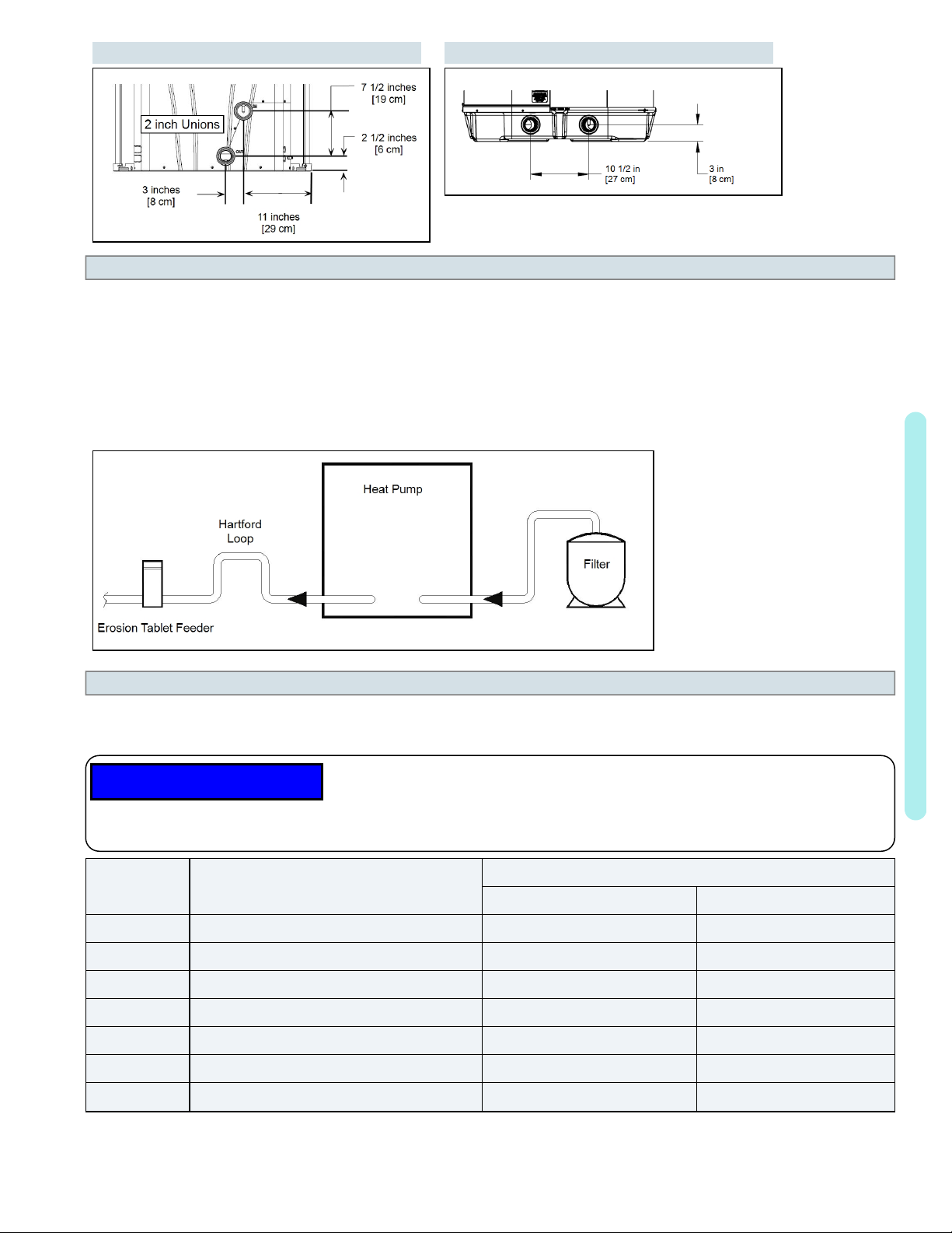
1.4.c Water Connections to Heat Pump
l Heat Pump union sizes are specified on diagrams.
l Connections to site plumbing are made via PVC solvent cement to the female slip socket of the plumbing unions.
l
Plumbing unions are available from AquaCal®.
NOTICE
l Do not use glue on the threaded portion of the equipment’s unions. A glued-in-place union will prevent the
Failure to heed the following may result in damage to equipment.
equipment from being properly winterized.
HeatWave SuperQuiet®SQ120R, SQ125,
1 - Installation
SQ145, SQ166R, SQ225
TropiCool®TC500
TropiCool®TC1500
TropiCool®TC1000 TropiCal®T035, T055, T075
Page - 10
TropiCal®T090, T115, T135 TropiCal®T170
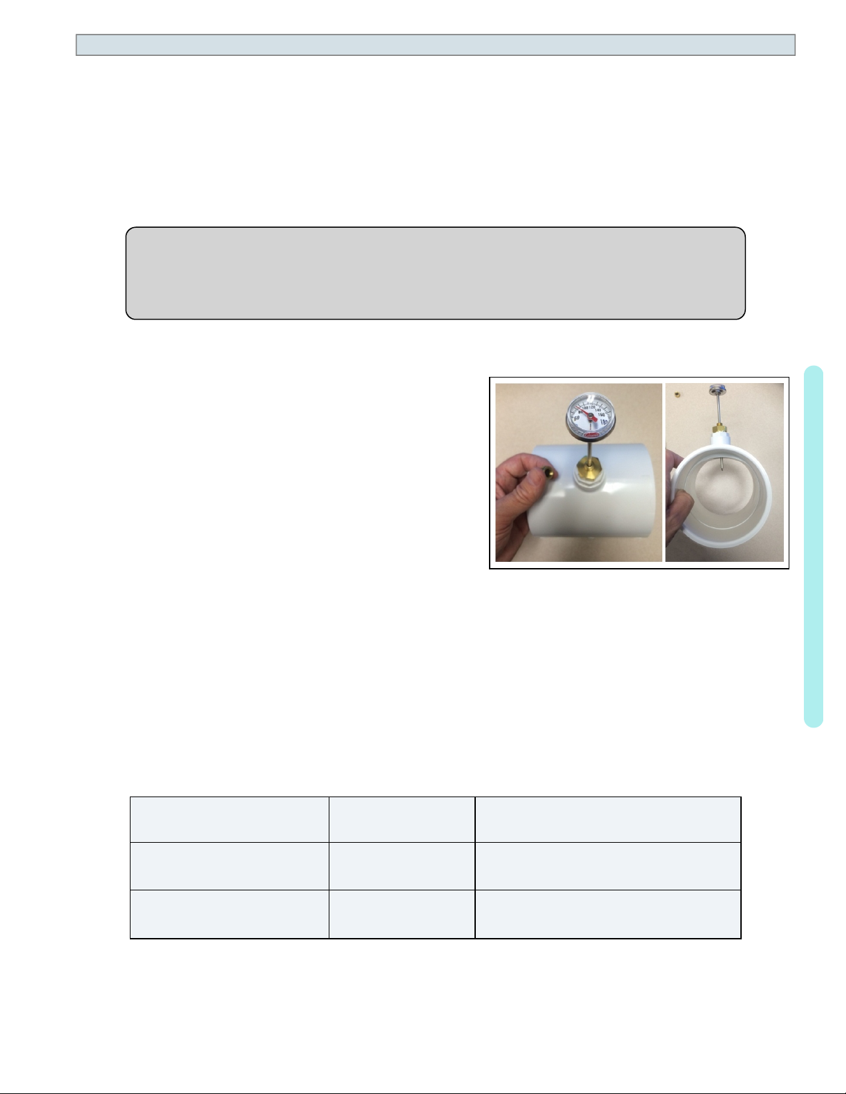
1.4.d In-Line Chlorine Feeders
Place in-line chlorinators downstream from the heat pump and as low in elevation as possible.
l If an erosion type feeder is used, it is recommended that a Hartford Loop be installed to protect internal heat
pump components.
l A Hartford Loop is not necessary with a Salt Chlorine Generator.
Heat Pump with Hartford Loop
1.4.e Water Flow Rates
Maintain water flow rates as indicated. Please note, these specifications relate to the heat pump only. Codespecified whole system turnover rates must be satisfied.
NOTICE
l Water flow exceeding maximum flow rates will negatively affect the total pool filtration performance and may
damage the heat pump. This will not be covered under the equipment warranty.
Failure to heed the following may result in damage to equipment.
FLOW RATES
MODEL HEAT EXCHANGER TYPE
MINIMUM MAXIMUM
SQ120R Titanium ThermoLink
SQ125 Titanium ThermoLink
SQ145 Titanium ThermoLink
SQ150VS Titanium ThermoLink
SQ166R Titanium ThermoLink
SQ225 Titanium ThermoLink
®
®
®
®
®
®
30 GPM (113.6 L/min) 70 GPM (265 L/min)
30 GPM (113.6 L/min) 70 GPM (265 L/min)
30 GPM (113.6 L/min) 70 GPM (265 L/min)
30 GPM (113.6 L/min) 70 GPM (265 L/min)
30 GPM (113.6 L/min) 70 GPM (265 L/min)
30 GPM (113.6 L/min) 70 GPM (265 L/min)
1 - Installation
T035 Titanium Tube-in-Tube 20 GPM (75.7 L/min) 45 GPM (170 L/min)
Page - 11

MODEL HEAT EXCHANGER TYPE
FLOW RATES
MINIMUM MAXIMUM
T055 Titanium Tube-in-Tube 20 GPM (75.7 L/min) 45 GPM (170 L/min)
T075 Titanium Tube-in-Tube 20 GPM (75.7 L/min) 45 GPM (170 L/min)
T090 Titanium ThermoLink
T115 Titanium ThermoLink
T135 Titanium ThermoLink
®
®
®
30 GPM (113.6 L/min) 70 GPM (265 L/min)
30 GPM (113.6 L/min) 70 GPM (265 L/min)
30 GPM (113.6 L/min) 70 GPM (265 L/min)
T170 Titanium Tube-in-Tube 30 GPM (113.6 L/min) 70 GPM (265 L/min)
TC500 Titanium Tube-in-Tube 20 GPM (75.7 L/min) 45 GPM (170 L/min)
TC1000 Titanium ThermoLink
TC1500 Titanium ThermoLink
®
®
30 GPM (113.6 L/min) 70 GPM (265 L/min)
30 GPM (113.6 L/min) 70 GPM (265 L/min)
PLEASE NOTE -
If minimum flow rates are not met, heat pump performance is reduced and performance will
suffer. Internal safety devices may deactivate the heat pump with the following errors:
l
HIGH PRESSURE FAULT
l
HP5 SYSTEM LOCKOUT
l
LOW PRESSURE FAULT
l
LP5 SYSTEM LOCKOUT
l Operate water filtration devices per manufacturer's specifications. Dirty filters can cause a reduction of water flow
to the heat pump. An increase of 7-10 psi (48 to 69 kPa) higher than the clean filter pressure typically reduces
flow rates. This requires the filter to be cleaned or back-washed.
l Keep baskets free of debris. A large quantity of debris in the pump and skimmer baskets can reduce water flow.
l Check for improper valve settings. A partially closed valve after the filter, or a full-open bypass around the heat
1 - Installation
pump, will cause insufficient water flow through the heat pump.
l The maximum static pressure (or operating pressure) is 50 psi (345 kPa). These specifications relate to the heat
pump only.
l Code-specified whole system turnover rates must be satisfied.
Page - 12
1.4.f Adjusting Water Flow Using ΔT (Delta-T)
The Delta-T is the temperature difference between the water temperatures entering and leaving the heat pump.
The equipment can be fine-tuned for maximum performance by balancing water flow rates to maintain an
ideal ∆T.
The adjustment procedure must be completed with the unit in heating mode.
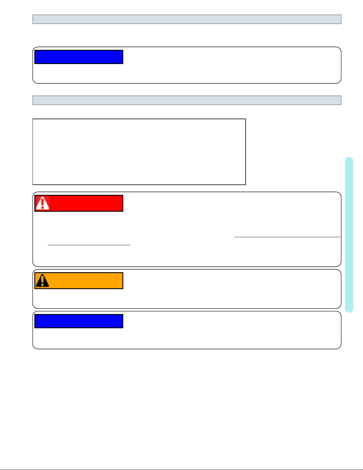
l Installed temperature ports are required to perform the following procedures.
l These ports are typically located on the pool in and pool out water lines approximately six inches away from the
heat pump.
PLEASE NOTE -
l The installation of temperature ports is required for all commercial applications.
l The installation of temperature ports is strongly recommended for residential installations.
n
See "Temperature Port Kit (# STK0096)" on page83.
Temperature Port
1.
Adjust the thermostat to its lowest setting with the unit in
heating mode.
2.
Deactivate the water filtration pump.
3.
Confirm that the filters leading to the heat pump are clean.
4.
Adjust the valves controlling water headed towards the heat
pump to the half-open position.
5.
Adjust the valves controlling water leading away from the
heat pump to a fully open position.
6.
Activate the pool water filtration pump.
7.
Slowly raise the thermostat temperature until the heat pump
activates.
l After a four-minute delay, the heat pump's compressor will start.
8.
With the heat pump running, confirm the filtration pump is operating properly with adequate flow and no short
cycling.
9.
Wait for water temperatures to stabilize (approximately 5 minutes).
(Shown with Probe)
1 - Installation
12.
Adjust valves in the following order using the temperature chart provided.
a.
Adjust the valve that controls water exiting the heat pump until the correct temperature differential is
achieved. Match the temperature measured with a temperature probe to the chart.
b.
Wait for water temperatures to stabilize. Then check the temperature again. Re-adjust the valve as needed.
13.
Mark valves at these positions for future reference.
HEAT EXCHANGER
TYPE
Titanium ThermoLink
®
MODEL TEMPERATURE
3° to 7° F
SQ120R
(1.7° C to 3.9° C)
Titanium ThermoLink
®
3° to 7° F
SQ125
(1.7° C to 3.9° C)
Page - 13

HEAT EXCHANGER
TYPE
Titanium ThermoLink
Titanium ThermoLink
Titanium ThermoLink
Titanium ThermoLink
®
®
®
®
MODEL TEMPERATURE
3° to 7° F
SQ145
(1.7° C to 3.9° C)
3° to 7° F
SQ150VS
(1.7° C to 3.9° C)
3° to 8° F
SQ166R
(1.7° C to 4.4° C)
4° to 9° F
SQ225
(2.2° C to 5° C)
1 - Installation
Tube-in-Tube
Tube-in-Tube
Tube-in-Tube
Titanium ThermoLink
Titanium ThermoLink
Titanium ThermoLink
Titanium Tube-in-Tube
Titanium Tube-in-Tube
Titanium ThermoLink
Titanium ThermoLink
®
®
®
®
®
T035
1° to 4° F
(.5° C to 2.2° C)
2° to 5° F
T055
(1.1° C to 2.8° C)
3° to 7° F
T075
(1.7° C to 3.9° C)
3° to 6° F
T090
(1.7° C to 3.3° C)
3° to 7° F
T115
(1.7° C to 3.9° C)
4° to 8° F
T135
(2.2° C to 4.4° C)
3° to 7° F
T170
(1.7° C to 3.9° C)
2° to 5° F
TC500
(1.1° C to 2.8° C)
2° to 5° F
TC1000
(1.1° C to 2.8° C)
3° to 7° F
TC1500
(1.7° C to 3.9° C)
Page - 14
Table 1 - Temperature Chart
PLEASE NOTE -
l Temperature differences are based on pool water temperatures of 69° to 75° F. (20.5° to
23.8° C)
l
For water temperatures outside this range, contact AquaCal®. See "Contacting
AquaCalAutoPilot, Inc." on page1.
1.4.g Maintaining Ability to Winterize
Do not glue the threaded portion of the unions. The unions are used to decouple the heat pump from the
plumbing system during hard freeze conditions.
NOTICE
l Do not use glue on the threaded portion of the equipment’s unions. A glued-in-place union will prevent the heat
Failure to heed the following may result in damage to equipment.
pump from being properly winterized.
1.4.h Adjusting Water Pressure Switch
Adjust the water pressure switch when heat pump attempts to operate without water flow.
Before attempting any adjustments confirm the following :
l The filter is clean.
l Filter pump is operating.
l The valves are set to direct the appropriate amount of water through the
heat pump. See "Water Flow Rates" on page11.
l
"NO POOL/SPA WATER FLOW" is displayed (or displays
intermittently).
Failure to heed the following will result in injury or death.
DANGER
l RISK OF ELECTRICAL SHOCK FROM ENERGY STORED IN CAPACITORS - MODELS EQUIPPED
WITH VARIABLE FREQUENCY COMPRESSOR DRIVES STORE ELECTRICITY EVEN AFTER THE
POWER HAS BEEN DEACTIVATED AT THE POWER BREAKER. Wait for 2 minutes after the shut down
of equipment before servicing.
l Deactivate power while routing wiring to control board.
l Follow all National Electric Codes (NEC) and/or State and Local guidelines.
1 - Installation
WARNING
Failure to heed the following may result in injury or death.
l Water Pressure Switch adjustment procedure to be performed by experienced service personnel only; procedure
must not be attempted by individuals lacking adequate electrical and mechanical experience.
NOTICE
l If the heat pump continues to operate after a water pressure switch adjustment, deactivate equipment and perform
additional troubleshooting.
Failure to heed the following may result in damage to equipment.
Page - 15
1.
Remove heat pump access panel.
2.
Locate the water pressure switch. It will be outside and along
the bottom edge of the electrical enclosure. The exact location
varies by model.
3.
Activate the filter pump.
4.
Apply power to heat pump.
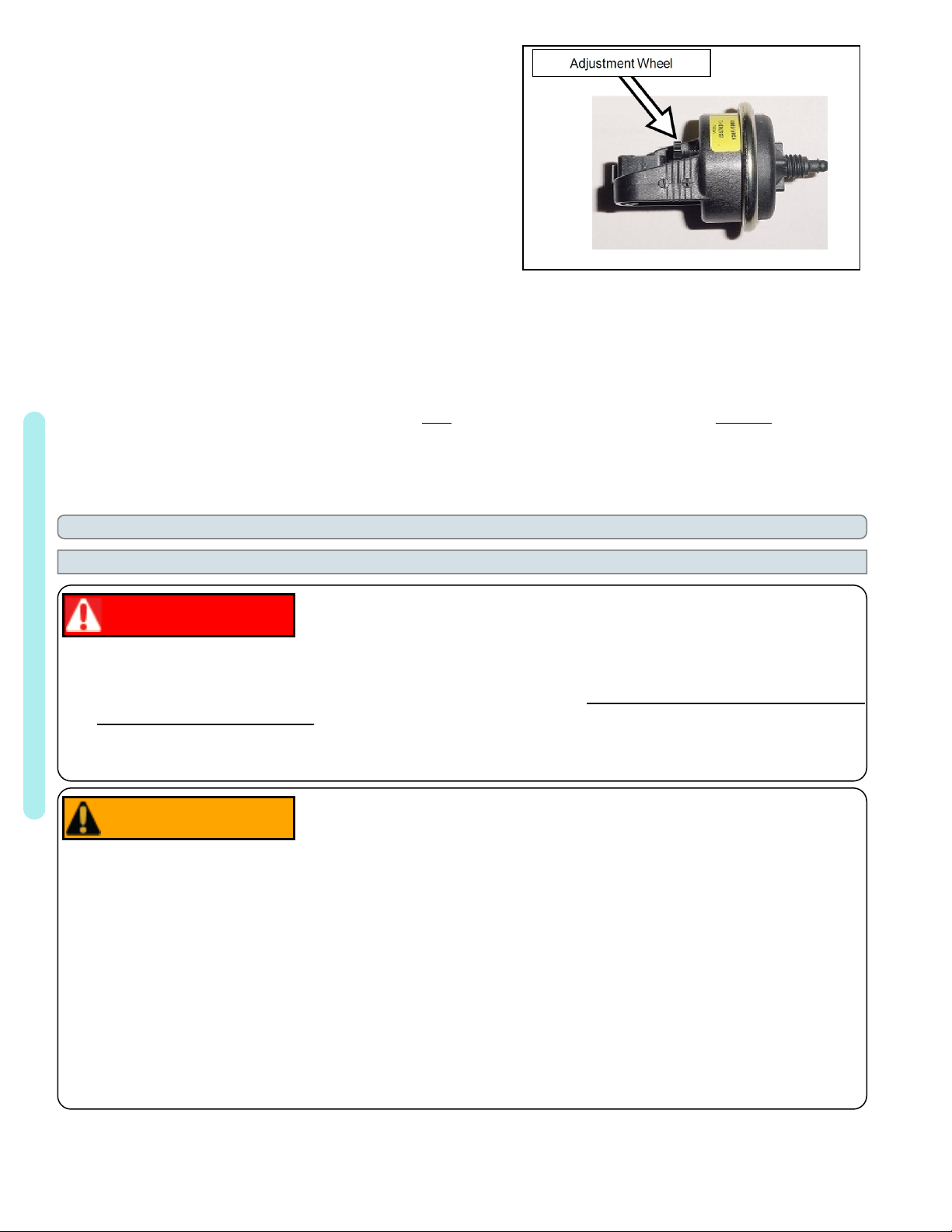
5.
Slowly rotate the adjustment wheel on the switch. Keep
turning the wheel until the heat pump indicates it is receiving
water. The display will no longer indicate "NO POOL/SPA
WATER FLOW".
6.
Deactivate filter pump. If correctly adjusted, theheat pump will deactivate and the display will show "NO
POOL/SPA WATER FLOW".
7.
Re-install heat pump access panel.
8.
If the heat pump continues to operate without water flow, the installation of a grid flow switch may be required.
l This can become necessary if the heat pump is installed below the elevation of the body of water to be heated
or cooled. The standing pressure from the water can cause the water pressure switch to activate when the
circulation pump is off. Therefore a water flow switch must be used in place of a water pressure switch to
determine if incoming water is being sent to the heat pump. See "Grid Flow Switch (# 0040S)" on page82.
9.
If the heat pump continues to operate without water flow, contact AquaCal®.
1.5 Electrical
1.5.a Electrical Requirements
Failure to heed the following will result in injury or death.
DANGER
l RISK OF ELECTRICAL SHOCK FROM ENERGY STORED IN CAPACITORS - MODELS EQUIPPED
1 - Installation
WITH VARIABLE FREQUENCY COMPRESSOR DRIVES STORE ELECTRICITY EVEN AFTER THE
POWER HAS BEEN DEACTIVATED AT THE POWER BREAKER. Wait for 2 minutes after the shut down
of equipment before servicing.
l Deactivate power while routing wiring to control board.
l Follow all National Electric Codes (NEC) and/or State and Local guidelines.
Failure to heed the following may result in injury or death.
WARNING
l The information contained in this section is intended for use by qualified electricians familiar with electrical
service-industry safety standards and methods.
l Locate the equipment disconnect as near to the heat pump as possible. Always satisfy applicable codes and
standards.
l Never mount power-disconnects directly to the heat pump.
l In sizing power wiring, be especially aware of up-sizing requirements necessary due to wiring distances. Always
satisfy applicable codes and standards.
l
AquaCal®heat pumps are designed to use copper conductors, only. Do not use aluminum wire.
l
If multiple heat pumps are on-site, confirm that the multiple heat pump configuration has been utilized. See
"Connecting Multiple Heat Pumps (Master / Slaved)" on page39. This will prevent multiple heat pumps
attempting to start at the same time, causing an excessive power drop at start-up.
Page - 16

Electrical Standards
Standards Title
NFPA 70, Nat'l Elec.
Code 2017
The electrical installation must conform to the current
version of the National Electric Code (NEC), and all
applicable local and state codes
IEC 60335-1 Household and similar electrical appliances - Safety -
General Requirements
IEC 60335-2 Household and similar electrical appliances - Safety –
Particular requirements for electrical heat pumps, airconditioners, and dehumidifiers
UL 1995 & CSA C22.2
No. 236-15
Standard for Safety - Heating and cooling equipment
Table 2 - Standards
Grounding and Bonding
Follow local code requirements for proper grounding and bonding of heat pump equipment.
l A bonding lug has been provided on the lower right-hand corner of the front access panel.
Surge Suppression
The use of approved commercial surge protectors is strongly recommended.
Sizing the Electrical Service
Refer to equipment data plate for specific information required to size electrical service and over-current
protection of the heat pump. Sizing is based on data plate information, wire size, wiring devices, and overcurrent protection per applicable local codes and standards. See "Identifying Model Specifications" on
page78.
1 - Installation
Page - 17

Minimum and Maximum Operating Voltage
The heat pump must operate within specified voltages.
NOTICE
l Operating equipment under higher or lower voltage conditions may result in damage to your compressor, motors
or other electrical components. This damage will not be covered by the product warranty.
1. Measure site voltage. The site voltage MUST be measured under “FULL LOAD” conditions. Activate all
equipment using the same electrical panel as the heat pump.
2.
If measured site voltage is outside listed ranges, immediately deactivate equipment until site conditions have been
corrected. If unsure of heat pump equipment rating, please see "Identifying Model Specifications" on page78.
Failure to heed the following may result in damage to equipment.
Equipment Rating
Minimum
Site Voltage
Maximum
Site Voltage
A Voltage
(208 to 230 Volts)
200 Volts 253 Volts
Single Phase 60 hertz
B Voltage
(208 to 230 Volts)
200 Volts 253 Volts
Three Phase 60 hertz
D Voltage
(380 to 420 Volts)
361 Volts 441 Volts
Three Phase 50 hertz
1 - Installation
E Voltage
(380 Volts)
Three Phase 60 hertz
G Voltage
(460 Volts)
Three Phase 60 hertz
H Voltage
(200 to 240 Volts)
Single Phase 50 hertz
361 Volts 399 Volts
437 Volts 483 Volts
180 Volts 264 Volts
Page - 18
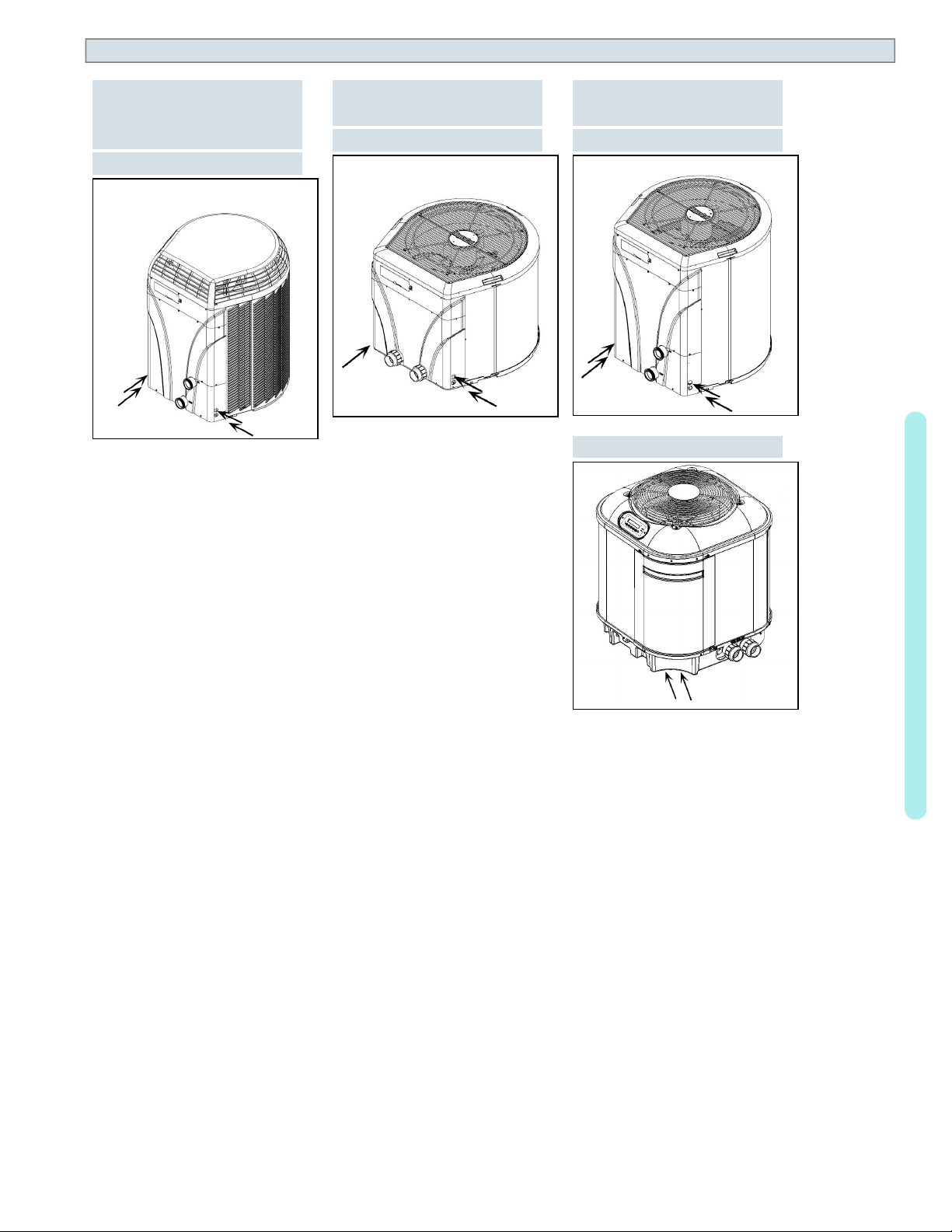
1.5.b Incoming Power Access Holes
(HeatWave SuperQuiet
SQ120R, SQ125, SQ145,
SQ166R and SQ225)
(TropiCool®TC1500)
®
(TropiCal®T035, T055
and T075)
(TropiCool®TC500)
(TropiCal®T090, T115
and T135)
(TropiCool®TC1000)
(TropiCal®T170)
1 - Installation
Page - 19
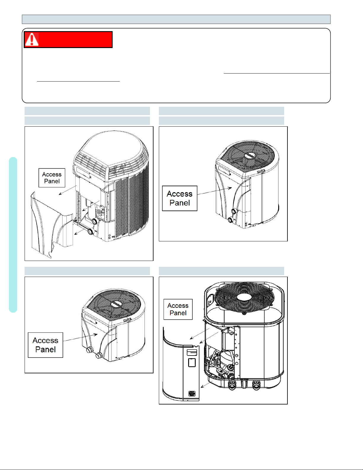
1.5.c Access Panels
DANGER
Failure to heed the following will result in injury or death.
l RISK OF ELECTRICAL SHOCK FROM ENERGY STORED IN CAPACITORS - MODELS EQUIPPED
WITH VARIABLE FREQUENCY COMPRESSOR DRIVES STORE ELECTRICITY EVEN AFTER THE
POWER HAS BEEN DEACTIVATED AT THE POWER BREAKER. Wait for 2 minutes after the shut down
of equipment before servicing.
l Deactivate power while routing wiring to control board.
l Follow all National Electric Codes (NEC) and/or State and Local guidelines.
HeatWave SuperQuiet
TropiCool®TC1500
®
TropiCal®T035, T055 and T075
TropiCool®TC1000
1 - Installation
TropiCool®TC500 TropiCal®T170
Page - 20
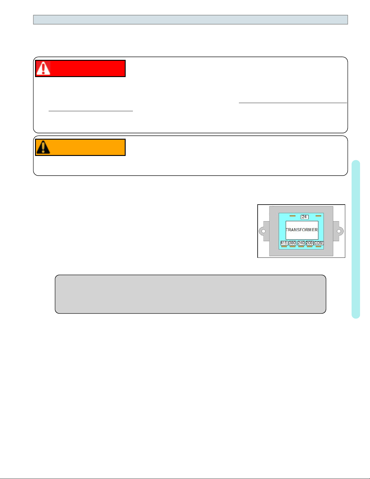
1.5.d Verifying Transformer Setting
Transformer voltage must be confirmed and set correctly depending on the measured voltage found on the
site. Incorrect settings may cause heat pump damage. The following procedure will allow the installer to set
the heat pump's transformer for the appropriate site voltage.
DANGER
Failure to heed the following will result in injury or death.
l RISK OF ELECTRICAL SHOCK FROM ENERGY STORED IN CAPACITORS - MODELS EQUIPPED
WITH VARIABLE FREQUENCY COMPRESSOR DRIVES STORE ELECTRICITY EVEN AFTER THE
POWER HAS BEEN DEACTIVATED AT THE POWER BREAKER. Wait for 2 minutes after the shut down
of equipment before servicing.
l Deactivate power while routing wiring to control board.
l Follow all National Electric Codes (NEC) and/or State and Local guidelines.
Failure to heed the following may result in injury or death.
WARNING
l The information contained in this section is intended for use by qualified technicians, familiar with electrical
service-industry safety standards and methods.
1.
Turn heat pump on by adjusting the thermostat to call for heating or cooling.
If more than one heat pump is on-site, turn them all on. Allow time for all
heat pump compressors to activate.
2.
Measure the running site voltage.
3.
Confirm transformer tap is set for the measured site voltage. If more than one
voltage tap is shown, select the voltage nearest to the running site voltage.
Example of heat pump
transformer
(Varies between models)
1 - Installation
PLEASE NOTE -
l If more than one voltage is shown on the equipment’s data plate, the factory default setting is
usually the higher voltage on the transformer.
l As an example, a "208/230" voltage will be set to "240" from the factory.
Page - 21
1.5.e Three-Phase Adjustment
DANGER
Failure to heed the following will result in injury or death.
l RISK OF ELECTRICAL SHOCK FROM ENERGY STORED IN CAPACITORS - MODELS EQUIPPED
WITH VARIABLE FREQUENCY COMPRESSOR DRIVES STORE ELECTRICITY EVEN AFTER THE
POWER HAS BEEN DEACTIVATED AT THE POWER BREAKER. Wait for 2 minutes after the shut down
of equipment before servicing.
l Deactivate power while routing wiring to control board.
l Follow all National Electric Codes (NEC) and/or State and Local guidelines.
Failure to heed the following may result in injury or death.
WARNING
l The information contained in this section is intended for use by qualified technicians, familiar with electrical
service-industry safety standards and methods.
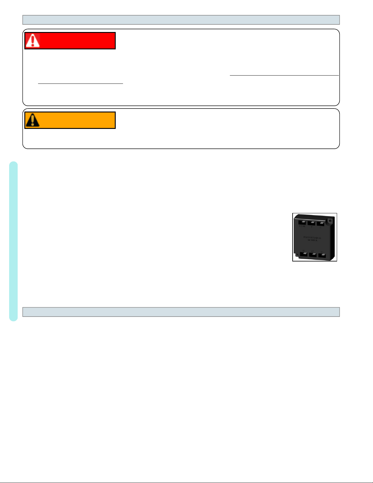
If a three-phase unit fails to operate at start-up, the orientation of the line voltage "field" wiring may need to be
adjusted.
l The phase monitor is located inside the electrical panel.
1. Deactivate power to the unit. Confirm that power is off to all three legs using an
electrical test meter set for the correct voltage.
2.
Switch position of the incoming power wires at each leg as follows, re-connect power and
attempt to restart the unit. If the unit fails to start, disconnect power. Verify off and proceed to
the next leg.
l Switch incoming power wires at L1 and L2 on the line side to the contactor.
l Switch incoming power wires at L1 and L3 on the line side to the contactor.
1 - Installation
3.
l Switch incoming power wires at L2 and L3 on the line side to the contactor.
When heat pump starts, disconnect power and verify off. Then confirm all line voltage
connections are securely tightened. Reconnect power.
Three-Phase
Monitor
l
If the heat pump does not start, contact AquaCal®for further assistance. See "Contacting
AquaCalAutoPilot, Inc." on page1.
1.5.f Schematic Location
Schematics are located on the inside of the electrical panel.
Page - 22
1.6 External Equipment
1.6.a Connecting a Call Flex
To support a direct connection to a call flex accessory, AquaCal®heat pumps are equipped with optional
terminal blocks on the microprocessor. The microprocessor is located on the low-voltage side of the electrical
enclosure.
The call flex accessory can override a circulation pump to provide water flow to the heat
pump when the set temperature is not met. For ordering information on the accessory, see
"Call Flex Accessory (# 0030-LEDS)" on page82.
Connecting a Call Flex
DANGER
Failure to heed the following will result in injury or death.
l RISK OF ELECTRICAL SHOCK FROM ENERGY STORED IN CAPACITORS - MODELS EQUIPPED
WITH VARIABLE FREQUENCY COMPRESSOR DRIVES STORE ELECTRICITY EVEN AFTER THE
POWER HAS BEEN DEACTIVATED AT THE POWER BREAKER. Wait for 2 minutes after the shut down
of equipment before servicing.
l Deactivate power while routing wiring to control board.
l Follow all National Electric Codes (NEC) and/or State and Local guidelines.
Failure to heed the following may result in injury or death.
WARNING
l This section is only for qualified installers who are familiar with the swimming pool and spa safety standards.
l The installer must be familiar with service industry techniques.
NOTICE
l The wire size connecting the controller must be 22-gauge (minimum), 2-conductor, low-voltage wire.
1.
Deactivate power to heat pump.
2.
Remove heat pump electrical access panel.
3.
Route 22-gauge (minimum), 2-conductor, low-voltage wires
to the low voltage side of the electrical enclosure. Follow all
National Electric Codes (NEC) unless State or Local
guidelines supersede.
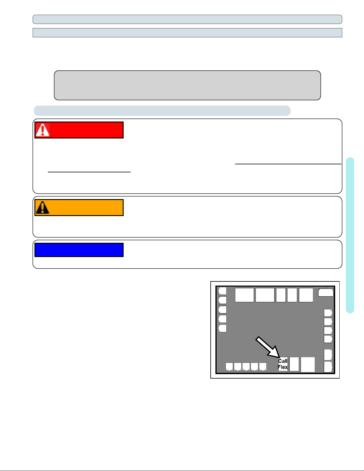
4.
Connect the controller wires to the port labeled "Call Flex"
on the microprocessor as indicated.
5.
Reattach heat pump access panel.
6.
Apply power to heat pump.
7.
Configure the heat pump to indicate an installed Call Flex.
See "Configure Call Flex" on the next page.
Failure to heed the following may result in damage to equipment.
Connection Points to the Microprocessor
1 - Installation
Page - 23
 Loading...