

Aquacal H100BR, H100AR, AT100AR, AT100BR, H100DR Owner's Manual And Installation Manual
...
and
Pool and Spa
Heat Pump
&7
Owner’ s Manual
and
Models:
H/AT100R
Installation Guide
PN: L TP0010
01/30/04
A TTENTION INST ALLER:
THIS DOCUMENT IS PURCHASER’S PROPERTY AND IS TO REMAIN WITH THE HEAT PUMP OWNER
H/AT120R
Also Applies to:
XL100R
XL120R
1/7/04
1

1-800-786-7751
NOTES
___________________________________________________________________________________
__________________________________________________________________________________
___________________________________________________________________________________
_________________________________________________________________________________
_________________________________________________________________________________
_________________________________________________________________________________
___________________________________________________________________________________
__________________________________________________________________________________
___________________________________________________________________________________
_________________________________________________________________________________
__________________________________________________________________________________
________________________________________________________________________________________
___________________________________________________________________________________
____________________________________________________________________________________
_________________________________________________________________________________
__________________________________________________________________________________
_________________________________________________________________________________
__________________________________________________________________________________
__________________________________________________________________________________
2

TABLE OF CONTENTS
WELCOME TO THE TEAM ------------------------------------------------------- 5
IMPORTANT FEATURES OF YOUR NEW HEAT PUMP ------------------- 6
SAFTEY INFORMATION ---------------------------------------------------------- 7
QUICK START & STOP------------------------------------------------------------ 9
PHYSICAL CHARACTERISTICS & SPECIFICATIONS -------------------- 10
Dimensional Information----------------------------------------------------------- 1 0
Specifications ----------------------------------------------------------------------- 11
Data Plate Nomenclature----------------------------------------------------------- 11
INSTALLATION ---------------------------------------------------------------------- 12
Placement of Heater----------------------------------------------------------------- 12
Plumbing Requirements ------------------------------------------------------------ 13
Electrical Requirements------------------------------------------------------------- 16
Connecting External Controllers------------------------------------------ 16
START-UP & OPERATION --------------------------------------------------------- 17
Control Panel Features ------------------------------------------------------------- 17
Overview of Controls--------------------------------------------------------------- 18
Initial Start-up and Basic Operation----------------------------------------------- 1 8
Heating T ips-------------------------------------------------------------------------- 20
Calculating Initial Heating Time --------------------------------------------------- 21
3

TABLE OF CONTENTS, continued
MAINTENANCE---------------------------------------------------------------------- 22
Planned Maintenance Program---------------------------------------------------- 2 2
General Maintenance --------------------------------------------------------------- 23
Maintaining Proper Water Flow--------------------------------------------------- 24
Maintaining Proper Clearances --------------------------------------------------- 24
SEASONAL USE & SHUT DOWN ----------------------------------------------- 24
During the Swim Season ----------------------------------------------------------- 24
Freeze protection / Extended Shut Downs--------------------------------------- 24
W interizing (Hard Freeze Conditions) ------------------------------------------- 25
TROUBLESHOOTING-------------------------------------------------------------- 28
Common Troubleshooting Issues------------------------------------------------- 28
Troubleshooting Flow Charts------------------------------------------------------ 29
Adjusting Water Flow (Pressure) Switch ---------------------------------------- 33
Defrost System: Description & Troubleshooting ------------------------------ 35
T roubleshooting Problems in the Refrigerant Circuit -------------------------- 37
Refrigerant Circuit Performance (T-P) Charts ---------------------------------- 38
REPLACEMENT PARTS ----------------------------------------------------------- 41
CONTACTING THE FACTORY -------------------------------------------------- 42
4
Welcome
to the
T
Dear Owner:
ongratulations on your wise decision to make an AquaCal heat pump part of
your home. Since 1981, AquaCal has maintained the worldwide lead in the
C
only a great investment, but also the most cost effective method available for heating
pools and spas. For example, your heat pump is up to 400% more efficient than gas,
and, when compared to electric resistance
heat, your heat pump is nearly 600% more
effective. You can rest assured that your new
heat pump is of the highest quality and
efficiency , and is designed and built to provide
years of trouble-free operation.
Moreover, should you decide you would like
AquaCal to provide regular inspection and
maintenance of your heat pump—which we
do recommend—you will find that AquaCal’ s
factory-trained service staff is the largest and
most-qualified in the pool & spa heat pump
industry.
manufacture of swimming pool & spa heat pumps. Your new heat pump is not
eam
“You can rest assured
that your new heat
pump is of the highest
quality and efficiency,
and is designed and
built to provide years of
trouble-free
operation.”
5

Important Features of Your New
Icebreaker Heat Pump
ThermoLink
Heat Exchanger
The heart of your heat
pump is the patented
ThermoLink heat exchanger. The primary
cause of premature heat
pump demise is the failure
of the heat exchanger.
Ordinary heat exchangers
are made from a cupronickel alloy. This cupronickel material is susceptible to attack from the
sanitizers used in pools and
spas, and from other related water chemistry conditions. Once the heat exchanger fails, the heat
pump is ruined. The
ThermoLink heat exchanger tube is made from
titanium, and is virtually impervious to water chemistry damage.
D
D
D
D
D
ThermoLink
Heat Exchanger
Electronic Controller
Corrosion-Resistant
Cabinet
Scroll Compressor
Heat & Cool + Hot Gas
Defrost
Electronic
Controller
State-of-the-art, solidstate electronic controller,
maintains water temperature within 1ºF of set point.
Controller also permits user
to predefine different Pool
and Spa water temperature
set points.
Corrosion-Proof
Cabinet
The cabinet, being made
from resilient, UV-Protected ABS material, can
never rust, fade, or corrode. You can expect the
cabinet to retain a likenew appearance with only
an occasional wash down
and—if so desired— a
quick waxing.
Scroll Compressor
50% fewer moving parts than standard piston-type compressors. This equates to much improved reliability and
improved efficiency . Scroll compressors are also much quieter in operation than piston-type compressors.
Heat & Cool Capability
Puts you in full control, year round ...W arms your pool or spa with the reliability and efficiency of our other heat
pumps, but, with the flip of a switch, can also cool your pool or spa to refreshing temperatures during the hot
summer months. For cooler climates, Icebreaker heat pumps offer unique advantages over passive defrost
models. Please read more below...
Hot Gas, Icebreaker Defrost
Your Icebreaker heat pump is uniquely equipped for active defrost. Active defrost involves directing hot refrigerant gas to the heat collector, melting accumulated ice away in a matter of a few minutes—then right back to
heating. Standard heat pumps may remain “off in defrost” for extended periods during very cold weather.
Because of its ability to continue to operate even during freezing weather, your Icebreaker extends the swim-
ming season longer than any other heat pump.
PLEASE SPEND A FEW MINUTES READING FURTHER TO BECOME
FAMILIAR WITH ALL THE FEATURES, THE SAFE OPERATION, AND THE
6
CARE OF YOUR NEW HEAT PUMP.
SAFETY INFORMATION
Used and maintained properly , your heat pump will provide year-upon-year of safe and economical service.
However, as with any mechanical or electrical device, to get the most from your heat pump–while insuring
personal safety for you and others–certain operational and maintenance factors must be observed.
Likewise, excepting a few minor owner-capable maintenance items (explained later in this manual), repair and
service of your heat pump must be performed only by experienced service personnel. Should you, the owner,
suspect your heat pump is not performing properly, by referring to the section in this manual entitled:
"Troubleshooting", you will be able to determine if a call for service is required. Y our installer can be one
source of service, or AquaCal Customer Support personnel stand ready to assist you at: (800) 786-7751.
For questions concerning installation, modifications, operation, service and upkeep, please contact your installer
or AquaCal Customer Support. W arranties may be voided if the heater has been used, maintained, or repaired
improperly .
In addition to possible voiding of warranties: unapproved installation methods, nonstandard modifications,
poor or incorrect maintenance, service by unqualified personnel, or improper use of this unit, may result in
personal injury and/or property damage. For personal safety and to avoid damage to equipment, it is important
that safety instructions displayed on the heat pump, and within this manual, are read, understood, and followed.
Throughout this manual the following two safety signals are placed where particular care is required. Please
note "W ARNING" relates to personal safety , while "CAUTION" signals promote avoiding damage to equipment.
Failure to heed the following may result in permanent injury or
WARNING !
This “W arning” symbol appears in this manual where special attention is required for personal safety .
Specific instructions will appear in this box.
CAUTION !
This “Caution” symbol appears in this manual where special care is required to avoid equipment damage.
Specific instructions will appear in this box.
death.
Failure to heed the following may result in damage to equipment.
Water Temperature Safety
Failure to heed the following may result in permanent injury or
WARNING !
Prolonged immersion in water warmer than normal body temperature may cause a condition known as
HYPER THERMIA. The symptoms of hyperthermia include: unawareness of impending hazard, failure
to perceive heat, failure to recognize the need to exit the spa, and unconsciousness. The use of alcohol,
drugs, or medication can greatly increase the risk of fatal hyperthermia. In addition, persons having an
adverse medical history , or pregnant women, should consult a physician before using a hot tub or spa.
Children and the extreme elderly should be supervised by a responsible adult.
death.
7
Heater NOT Repairable by Owner
Failure to heed the following may result in permanent injury
WARNING !
Heat pumps contain no owner-repairable components. Repairs must not be attempted by untrained
and/or unqualified individuals. If service is deemed necessary , contact installing dealer or AquaCal
Customer Support at (800) 786-7751.
or death.
Refrigerant Circuit Service Only by
Qualified, EP A Certified T echnician
Failure to heed the following may result in permanent injury
WARNING !
Heater contains refrigerant under high pressure. Repairs to the refrigerant circuit must not be attempted
by untrained and/or unqualified individuals. Service must be performed only by qualified HVAC
technicians. Recover refrigerant to relieve pressure before opening system.
or death.
W ater Chemistry Safety
Failure to heed the following may result in permanent injury or
WARNING !
Improper water chemistry can present a serious health hazard. T o avoid possible hazards, maintain
Pool/Spa water per standards below .
CAUTION !
While your heat pump’s titanium-based heat exchanger provides nearly impervious protection against
poor water chemistry , improper water chemistry may cause expensive damage to pump, filter, pool
shell, etc. T o avoid equipment damage, maintain Pool/Spa water per standards below .
death.
Failure to heed the following can result in damage to equipment.
RECOMMENDED W A TER CHEMISTRY ST ANDARDS
Chlorine . . . . . . . . . . . . . . .:
Bromine . . . . . . . . . . . . . . .:
pH . . . . . . . . . . . . . . . . . . .:
T otal Alkalinity . . . . . . . . . .:
Calcium Hardness . . . . . . . .:
T otal Dissolved Solids . . . . .:
1.0 – 3.0 ppm in pools, 1.5 – 3.0 ppm in spas
2.0 – 4.0 ppm in pools, 3.0 – 5.0 ppm in spas
7.4 – 7.6 ppm in pools, 7.2 – 7.8 ppm in spas
80 – 140 ppm in pools, 80 – 120 ppm in spas
200 – 400 ppm in pools and spas
1,000 – 2,000 ppm in pools,
1,500 ppm above start-up TDS in spas
8

HEATING-QUICK START & STOP
his brief information is provided as an aide to installers, service personnel, and owners. The intent of this
section is to provide rapid access to (only) very basic operational information. Individuals who will be
T
routinely using, installing, maintaining, and servicing this heat pump, are strongly encouraged to read this
entire manual. If uncertain about any instructions given herein, AquaCal Customer Support (800-786-7751)
should be contacted for additional information. Note: The terms “Heat Pump” and “Heater” are used
synonymously .
S tart Up
1. With water pump OFF , position water valves to heat the POOL or SP A.
2. Set water pump controls to allow for temporary , continuous operation.
3. Rotate both thermostats counterclockwise to lowest temperature settings.
4. Depending on valve settings (per #1, above), position the POOL/OFF/SP A toggle switch to point at
either the POOL or SP A thermostat knob. Set HEAT/COOL toggle switch to HEAT position.
5. Ensure power is supplied to the heater, then start the water pump; the POWER and FLOW lights
should now both be lit. Permit the water pump to operate for five (5) minutes before proceeding.
Setting the Temperature Controls - Pool or Spa
1. Turn the selected pool or spa thermostat dial clockwise to its highest setting.
2. The heat pump will start and begin to warm the pool or spa.
NOTE: The heat pump utilizes a short-cycle time delay device. If heat pump does not
start, wait five (5) minutes; the time delay may be preventing the heat pump from starting.
3. Initially , the typical spa may take several hours to heat, while a pool may take several days. Heating
time will depend on the volume of water, beginning water temperature, and the weather conditions at
the time of start-up. (Also see T able of Contents item: Calculating Initial Heating T ime.)
4. When the pool or spa reaches the desired temperature, slowly rotate the thermostat knob
counterclockwise until the heat pump (just) stops. The thermostat is now positioned to automatically
maintain the set temperature.
Once the heat pump has brought the pool or spa up to temperature, it will be necessary to reset the
pump run-time controls. Be sure to allow enough running time for the heat pump to replace lost heat.
Required run time will vary depending upon the time of year . Colder months require longer running
times–generally eight to twelve hours/day .
Switching Controls from Pool to Spa
NOTE: It is best to stop the water pump while repositioning valves.
1. Open spa valves and close pool valves.
2. With the spa water circulation pump operating for at least five minutes, move the POOL/OFF/SP A
toggle switch from the POOL setting to the SP A setting.
3. Turn the Spa thermostat fully clockwise (104º F). Heat pump should start (also see time delay note,
above).
4. Initially, the typical spa may take several hours to heat. Heating time will depend on the volume of
water, beginning water temperature, and the weather conditions at the time of start-up.
5. When the spa reaches the desired temperature (104º F is maximum), slowly rotate the SP A
thermostat knob counterclockwise until the heat pump (just) stops. The spa thermostat is now
positioned to automatically maintain the set temperature.
The heat pump can be stopped by interrupting the electrical power supply , or by setting the desired temperature
lower than the actual water temperature. However, please note, if electrical power and water flow are present
to the heat pump, and the water temperature falls below 60ºF (with thermostat set to minimum), the heat pump
will operate to maintain the water temperature at 60ºF .
Time Clock Programming
To Stop the Heat Pump
9
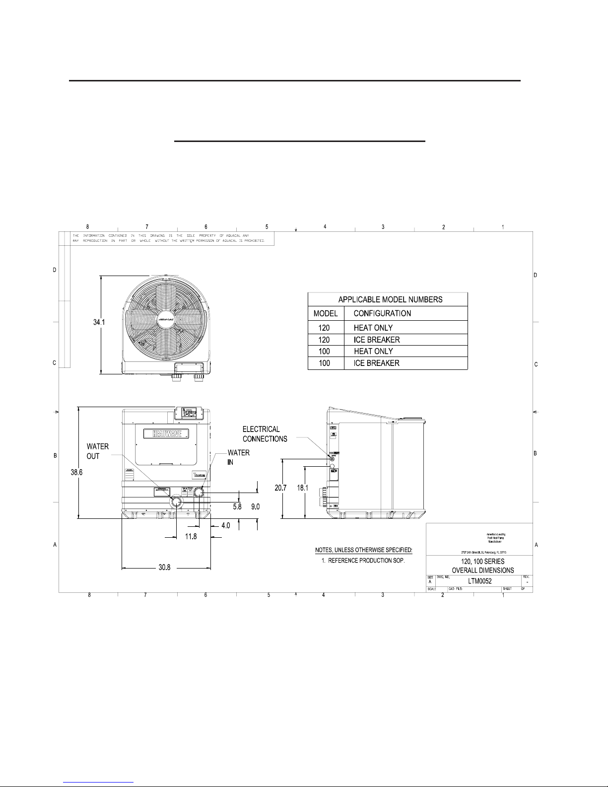
PHYSICAL CHARACTERISTICS
&
SPECIFICATIONS
Dimensional Information - Heat Wave/AeroTemp
100-120 Series (All Reversing Models)
10
Specifications — H/AT100R & 120R Models
SERIES:
SERIES:
100 -
H100AR
AT100AR
H100BR
AT100BR
H100DR
AT100DR
H100HR
AT100HR
BTU - 80%RH
Air ºF / Air ºF… 80/50
88,000/63,000
COP 5.6/4.1
BTU - 63% RH
Air ºF / Air ºF… 80/50
COP
Kilowatt Input (80% RH )
83,000/57,000
5.3/3.9
4.6
(DATA PENDING)
Voltage/Hz/Phase 208-230/60/1 208-230/60/3 380-415/50/3 220-240/50/1
Min. Circuit Ampacity 38.16 22.13 11.62 26.14
Rec. Fuse or Breaker Size
Max. Fuse or Breaker Size
40 30 15 30
60 35 20 40
Min-Max Water Flow (gpm) 20-70 20-70 20-70 20-70
Shipping weight (lbs) 320 320 320 320
Shipping Size (LXWXH)
Uncrated Weight
12 0-
BTU - 80%RH
Air ºF / Air ºF… 80/50
36” X 40” X 43" 36” X 40” X 43" 36” X 40” X 43" 36” X 40” X 43"
293 293 293 293
H120AR
AT120AR
H120BR
AT120BR
H120DR
AT120DR
H120HR
AT120HR
103,000/70,000
(DATA PENDING)
COP 5.4/4.1
BTU - 63% RH
Air ºF / Air ºF… 80/50
99,000/68,000
COP 5/3.8
Kilowatt Input (80% RH ) 5.6
Voltage/Hz/Phase
Min. Circuit Ampacity
208-230/60/1 208-230/60/3 380-415/50/3 220-240/50/1
38.16 26.14 12.82 36.56
Rec. Fuse or Breaker Size 40 30 15 40
Max. Fuse or Breaker Size 60 40 20 60
Min-Max Water Flow (gpm) 20-70 20-70 20-70 20-70
Shipping weight (lbs)
Shipping Size (LXWXH)
330 330 330 330
36” X 40” X 43" 36” X 40” X 43" 36” X 40” X 43" 36” X 40” X 43"
Uncrated Weight 303 303 303 303
Data Plate Nomenclature
1234567891011 12
AT120ARAEW N A
CURRENT RELEASED REVISION
BRAND
H = HeatWave OPTIONS
AT= AeroTemp N-NONE
SB = SouthBeach
TZ = Tropez
CAPACITY
100 = 90000 Btus/hr
120 = 109000 Btus/hr E - R22
155 = 120000 Btus/hr T - R407C
VOLTAGE
A - 1/60/208-230 D - DIGITAL
B - 3/60/208 - 230
D - 3/50/380
H - 1/50/200-220
RFRG CONTROL
H - HEAT
R - REVERSING
A - INITIAL RELEASE
CABINET COLOR
W - CRÈME
B - BLACK
REFRIGERANT
Z - R410A
CONTROLS
A - ANALOG
11
INSTALLATION
GU
R
Placement of Heater
Indoor Installation
Indoor installations can be problematic, and for that reason are discouraged. However, if no viable alternative
exists, indoor installations may be successfully accomplished provided very exacting criteria is addressed.
Every indoor installation is unique; therefore, there are no specific guidelines for this type of installation. If
considering an indoor installation, you are strongly urged to contact AquaCal Engineering or T echnical
departments (800-786-7751) for assistance prior to proceeding.
Outdoor Installation
Service and Operational Clearances:
♦ T o operate correctly , heat pumps require large volumes of air moving over the heat collector. Allow
adequate clearance between the heat pump and walls, fences, shrubs, or other objects. Refer to
recommended clearance drawings below .
♦ Allow five (5) feet of vertical clearance between the top of the heat pump and any roof overhang or other
obstruction. This clearance prevents cold discharge air from recirculating back into the heat pump
(recirculation would reduce the overall performance of the heat pump).
♦ The access panel requires removal during installation and service. Do not place plumbing, or other
items, closer than 30” from the front of the heater.
Code Required Clearances:
In addition to the previously stated clearance requirements, follow all applicable local, state, and national
requirements relative to spacing from other objects or equipment.
T ypical Installation Clearances
-
RAIN RUN
OFF MUST BE
DIRECTED
AWAY FROM
.
UNIT
30” M
INIMU M
C
LEARANCE
F
RONT
OVERHANG
WITH
,
TTE
5 FT.
MINIMUM
CLEARANCE
O
VERHEAD
1 FT.
C
LEARANCE
,
MINIMUM
,
24-
I
NCHES
(
SIDE
)
12-I
(R
30-I
(
NCHES
EAR
NCHES
FRONT
)
24-
NCHES
I
SIDE
(
)
)
12
FRONT-SIDES-REARFRONT-REAR-OVERHEAD

Irrigation, Rainwater Runoff, and Landscape Features:
Place the heat pump away from direct rain runoff from roofs. A gutter or rain shield may be required on the
roof edge above the heat pump. Relocate or adjust irrigation to avoid water spray directly onto the heat
pump. Do not locate the heat pump directly adjacent to plants, shrubs, or bushes. Doing so will prevent
proper air circulation into the unit, and may inhibit access to the heater when service is needed. Consult
drawings on previous page (Recommended Installation Clearances) for proper spacing to other objects.
Equipment Pad Requirements:
The equipment pad should be constructed of concrete, pressure treated wood, or other material intended
for the use. The pad shall be elevated and placed to provide adequate drainage and support to the base of
the heat pump. The pad should be essentially level with just enough pitch to drain condensate and any other
water away from the heater. In addition, the pad shall extend–in all directions–(at least) 3" beyond the base
of the heat pump. Under no circumstances shall the heater be installed directly onto the earth.
Anchoring Heater to Pad:
Follow all relevant local, state, or national requirements regarding wind load anchoring. When anchoring is
required, use AquaCal optional Hurricane Anchoring Kit, PN: STK0001. AquaCal anchoring kits satisfy ,
completely , the very stringent Florida Building Code Section 301.13 wind anchoring requirements. As
necessary , contact AquaCal Te chnical Support (800-786-7751) for assistance in determining best method
of compliance.
Plumbing Requirements
Overview:
When planning plumbing system layout, reference the plumbing schematics following this section as a guide to
the sequence of equipment, valves, fittings, etc. The plumbing configurations for typical installations are
diagrammed. In operation, it is imperative the heat pump receive water flow within the minimum-maximum
ranges specified for the particular heat pump. Should the system installation under consideration not closely
match any of the schematics, contact AquaCal T echnical Support for advice and guidance: (800) 786-7751.
Parts and Materials:
Industry technology changes much too rapidly for AquaCal to specify , with exactness, any items outside and
beyond the heat pump. What is specified is that the heater must be installed in accordance with all applicable
local, state, or national codes & standards.
Water Connections to Heat Pump:
All Heat W ave and AeroT emp heat pumps are supplied with 2" PVC plumbing unions. Connection to site
plumbing is made via PVC solvent cement to the female slip socket of the plumbing unions.
Maintain Ability to Winterize:
In regions where hard winters are typical, the unions mentioned above allow for easy disconnection/reconnection
of the heater from/to the plumbing system. Caution: Do not defeat the function of the unions–use no glue on the
threaded portion of the unions.
Maximum Operating Pressure: 50 PSI
Minimum/Maximum Water Flow Rates:
All Heat W ave and AeroT emp models are designed to operate successfully between flow rates of 20-to-70
gallons-per-minute (GPM). Design the plumbing system to maintain at least 20-GPM flow through the heater;
the heat pump will not operate correctly , nor reliably, with less than 20-GPM of water flow supplied. If water
flow rates through the heater will exceed 70-GPM, a 5-lb spring-check bypass valve (AquaCal P .N.: 2556)
will be required; generally speaking, most residential pools and spas will not require a bypass unless a pump of
two (2) horsepower or larger is used (for bypass valve placement details, see plumbing schematic contained
on next page: “…Flow Greater than 70-GPM”).
13
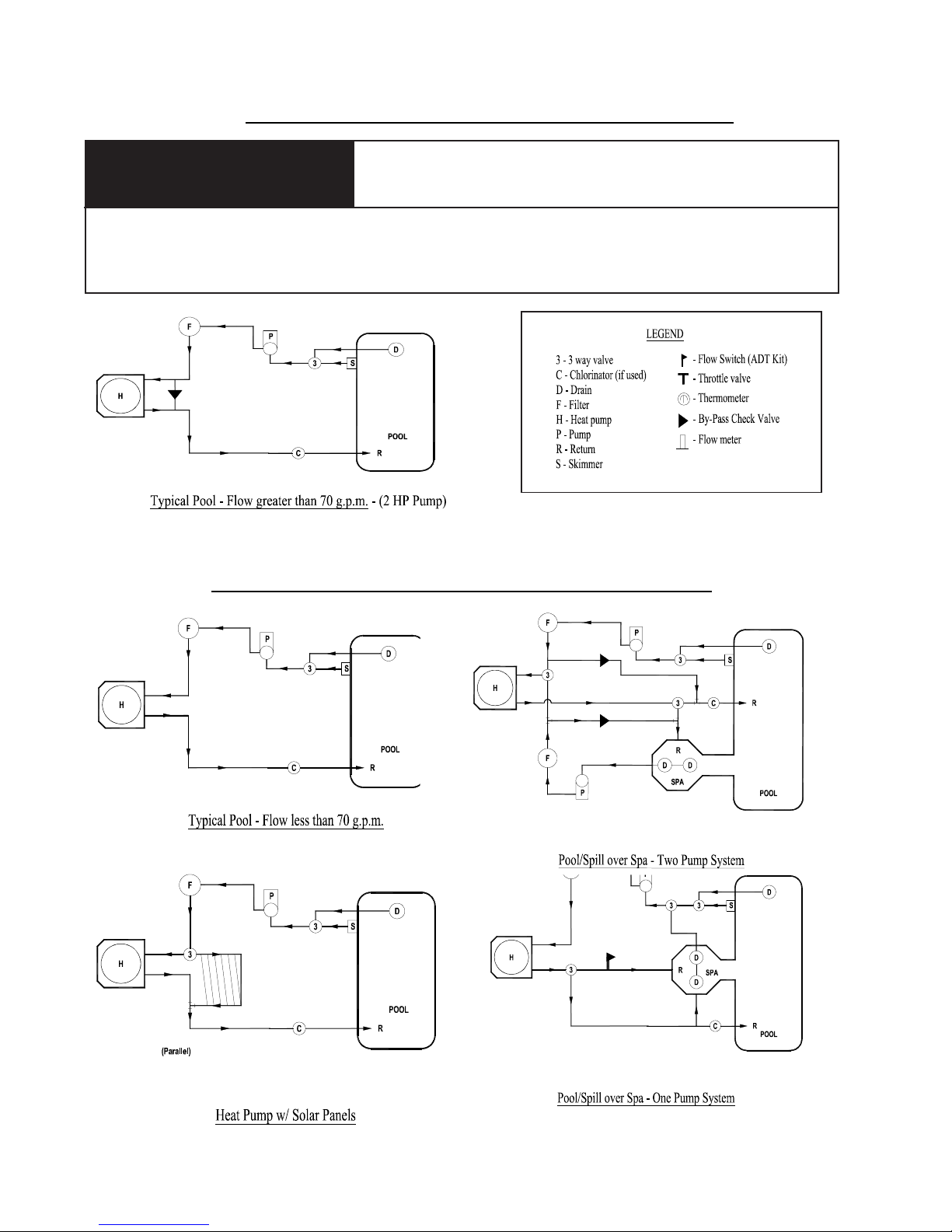
Plumbing Schematic–Flow Exceeding 70-GPM
CAUTION !
Use of an incorrect bypass valve may compromise the heat pump’s ef ficiency, reliability , and may void
the factory warranty . When using a bypass valve, order and install only an AquaCal PN: 2556 springcheck bypass valve.
Bypass Check
Failure to heed the following may result in damage to equipment.
Plumbing Schematics–Flow 70-GPM and Below
14

Plumbing Schematics–Flow 70-GPM and Below
(continued)
Water IN & OUT Connections:
For proper operation and maximum efficiency , piping coming from the pump and filter MUST be connected to
the "IN" port of the heater . Likewise, connect piping returning to the pool/spa to the "OUT" port of the heater.
See drawing below .
PLUMBING CONNECTION DETAIL
From Pump/Filter
Return to Pool/Spa
15

Electrical Requirements
Failure to heed the following may result in permanent injury
WARNING!
Installation made by unqualified persons can result in hazards to the installer and others. The information
contained in this Electrical Installation section is intended for use by qualified electrical installation
technicians, familiar with electrical service industry safety standards and methods. Electrical installation
to be performed by qualified individuals only .
General Requirements:
♦ When possible, locate the equipment disconnect means within arm’s reach of the heater’ s electrical
enclosure or as close as possible to the heater . Always satisfy applicable codes and standards.
♦ All AquaCal heat pumps are designed for copper conductors, only .
♦ In sizing power wiring, be especially aware of up-sizing requirements necessary due to wiring distances.
Always satisfy applicable codes and standards.
♦ Multiple heaters installed at same site generally require special sequencing controls (AquaCal P .N.:
ASC-(+number of heaters)); if yours is a multi-heater installation, contact AquaCal Technical Support
(800-786-7751) for application assistance.
♦ Electrical installation should be by licensed electrician only .
Code-Specific Requirements:
♦ The electrical installation must conform to the most current version of the National Electrical Code,
NFPA No.70, and all applicable local and state codes.
♦ National Electrical Code, Article 680; Swimming Pools, Fountains, and Similar Installations, shall apply .
or death.
♦ National Electrical Code, Article 440, Air-Conditioning and Refrigeration Equipment, shall apply .
Connecting External Controllers:
♦ See document entitled: “Connecting External Controllers to AquaCal Heat Pumps”. This document is
shipped inside heater, accompanying the electrical schematic. (For Call-Flex option, contact AquaCal
T echnical Support. All other controllers, reference document, per above, shipped with heater .)
Reference Equipment Data Plate:
♦ All Heat Wave and AeroT emp heat pumps have two (2) identical data plates affixed: one can be found
outside the unit, on right front side of fan top; the second data plate is located within the unit, on the
electrical enclosure cover. Refer to either equipment data plate for unit-specific electrical power supply
requirements. Based on data plate information; size wiring, wiring devices, and over-current protection
per applicable codes and standards.
♦ Refer to drawing below for data plate items specific to electrical installation requirements. On the actual
heater data plate, the areas depicted below (1-8) will contain the necessary information required in sizing
electrical service and over-current protection.
ELECTRICAL POR TION of DA T A PLA TE
16

START-UP & OPERATION
Getting Familiar with Controls
Heat W ave/AeroTemp
100R &120R Control Panel Features
1) POWER LIGHT – Indicates electrical power is supplied to the heater.
2) FLOW LIGHT – Indicates water pressure (flow) is present at the heater.
3) DEFROST LIGHT – Indicates heater is in the defrost mode.
4) HIGH REFRIGERANT PRESSURE – Indicates excessively high refrigerant pressure. Heater may
not be receiving adequate water flow .
5) LOW REFRIGERANT PRESSURE – Indicates abnormally low refrigerant pressure.
6) POOL TEMPERA TURE CONTROL – Controls POOL temperature set-point.
7) SPA TEMPERA TURE CONTROL – Controls SP A temperature set-point.
8) POOL/OFF/SP A SELECTOR SWITCH – Selects between POOL and SPA thermostats, or OFF
position.
9) HEA T/COOL SELECTOR SWITCH – Selects either HEATING or COOLING .
17

Overview of Controls
(Please refer to control panel diagram on previous page.)
POOL/OFF/SPA (P/O/S) Toggle Switch and Sequence of Operation
With the toggle switch in the OFF (O) position, the heater will be prevented from operating (however , there
may be power to the unit; see "Power Light On", below). With the toggle switch positioned toward the SPA
or POOL thermostat knob, with HEAT selected, and with the following conditions met: 1) water pump in
operation, with water flowing through the heater, and, 2) electrical power to the heater , the heater will run if the
water temperature drops below the thermostat setting. If COOL is selected, the heater will operate if the
water temperature rises above the thermostat set point.
Note- In Heat Mode, Heater Can S tart with Thermostats Set to Minimum:
With proper water flow and electrical power supplied to the heater , and either the POOL or SP A thermostat
selected and set to minimum, the heater will operate if the water temperature falls below 60º F . Likewise,
if mode is set to COOL, with thermostats set to maximum, and in the unlikely event the water temperature
rises above 104º F , the heat pump will operate to cool the water to a point below 104º F . If heat pump
operation is absolutely not desired, position the POOL/OFF/SP A toggle switch to the middle, OFF position.
Power Light On
Indicates electrical power is supplied to the heater. The heat pump will start if the selected (POOL or
SP A) thermostat calls for heating or cooling, and there is proper water flow through the heater .
Power Light Off
Indicates proper electrical power is not supplied to the heater. If attempting to operate the heater , ensure
all heater-related disconnect switches and/or circuit breakers are switched to the ON position.
Flow Light On
Indicates sufficient water flow to permit the heater to operate. The heat pump will start upon a call for
heating or cooling.
Initial Start-Up and Basic Operation
(Please refer to "Overview of Controls", above, before continuing.)
1. Set P/O/S T oggle Switch to OFF—Lower or Raise Thermostat Settings:
♦ Position the POOL/OFF/SP A toggle switch to "OFF".
♦ If preparing to HEA T , turn both thermostat knobs counterclockwise to lowest settings. If preparing to
COOL, turn both thermostat knobs clockwise to highest settings.
2. Establish Water Flow and Electrical Power to the Heat Pump:
♦ With circulator pump off, position the water valves to heat or cool either the pool or the spa. If
system is equipped with an external pump/valve/heater controller, simply use controller to position
valves to pool or spa setting, and to start the appropriate water pump.
♦ Ensure any heat pump-related disconnect switches, or circuit breakers, are switched to the ON
position.
♦ If not already operating, start the pool or spa pump (depending of which body of water is to be
heated or cooled), permitting the pump to operate for a few minutes before going on to next step.
This wait is necessary to clear any air that may exist in the water piping.
♦ The heat pump will not start without electrical power and water flowing through it. At this point, the
power light and flow lights should be illuminated.
18

3. Select POOL or SP A & HEA T or COOL, Raise or Lower Associated Thermostat:
♦ Position the POOL/OFF/SPA toggle towards the POOL or SP A thermostat knob (depending on
which body of water you are preparing to heat or cool).
♦ For Heating, move HEA T/COOL toggle to HEAT , then turn the selected pool or spa thermostat dial
clockwise to its highest setting. As soon as the thermostat setting is above the temperature of the
water, the heat pump will begin to operate. See note below if heater does not start
immediately .
♦ For Cooling, move HEA T/COOL toggle to COOL, then turn the selected pool or spa thermostat
dial counterclockwise to its lowest setting. As soon as the thermostat setting is below the temperature of the water, the heat pump will begin to operate. See note below if heater does not start
immediately .
Note- Heater Controls Contain a Solid-S tate Time Delay Module
This time delay feature prevents damage to the compressor should electrical power be repeatedly interrupted, or if the heat pump were to come under any other circumstances leading
to an on-off-on-off cycling condition. If the heater has water flow and electrical power supplied, but the heater does not immediately start upon turning the thermostat to its highest (or
for cooling, lowest) setting, wait five (5) minutes; the time delay module may be preventing the
heater from operating. Likewise, once the heater is operating, if the thermostat is turned past
the present water temperature, the heat pump will shut off. Subsequently , the heater cannot
restart for approximately five (5) minutes– no matter how far the thermostat is rotated.
4. Ensure Uninterrupted Pump Operation During Initial Warm-Up or Cool-Down Period:
♦ Permit pool or spa circulator pump to run continuously until the desired water temperature is
reached (with a pool, this may take several days).
♦ Continuous pump operation will likely require temporarily resetting (or removing completely) the
trippers on the time clock, thus allowing nonstop operation. When an external electronic controller
operates pumps and valves, follow the controller manufacturer's instructions to ensure temporary ,
uninterrupted pump operation.
♦ Throughout the warm-up or cool-down period, keep the selected pool or spa thermostat dial set to
its maximum heating or cooling position.
5. Desired W ater Temperature Reached– Set Thermostat to Maintain:
♦ If Heating, once the desired water temperature has been achieved, rotate the thermostat knob very
slowly counterclockwise until the unit (just) shuts off.
♦ If Cooling, once the desired water temperature has been achieved, rotate the thermostat knob very
slowly clockwise until the unit (just) shuts off.
♦ The heater will automatically maintain the pool or spa at the selected temperature.
6. Return Pump Timer Controls to Normal Settings:
♦ Reset pump timer controls for normal daily hours of operation.
♦ During cooler or cold weather conditions, it may become necessary to extend the daily hours of
pump operation; doing so will help the heater to keep up with increased heat losses. Extending
pump operation hours for cooling is not generally required.
♦ Also see next topic: "Heating Tips,” following on next page.
19

Heating Tips
Failure to heed the following may result in permanent injury or
WARNING !
Improperly used, Pool-Spa solar blankets can become a drowning risk to people and pets. Solar
blankets are not safety covers. They are not designed to support the weight of a person or pet.
Never enter a pool until the solar cover is completely removed (under no circumstances should
anyone swim under the blanket). Follow all safety recommendations of the blanket manufacturer.
A solar blanket will significantly reduce your heating bills. Check with the installing dealer to see if your heat
pump was sized to be used in conjunction with, or without a solar blanket. Blanketed pools will typically lose
only 3 - 4° of heat per night versus 8 - 10° overnight with an un-blanketed pool. Reductions of 40 - 60% on
heating bills can be achieved by using solar blankets.
Pool and Spa Combination Heating
Everything stated for heating a pool applies for heating a spa; only the volume of water being heated is different.
Heat W ave and AeroTemp model heat pumps come equipped with two thermostats. One thermostat is for the
pool and the other is for the spa. Simply position the pool and spa isolation valves as directed by your installer;
select the appropriate thermostat (pool or spa), whichever you are heating, and with electrical power and
water flow supplied to the heater, the water will be maintained at set point.
death.
Pool/Spa Blankets
Your system can be automated with the addition of an optional AquaCal Universal Heater Controller
(AquaCal part #0097TS). Using this option will save you from having to change the thermostat switch each
time you change from pool to spa and back again. For details, contact your installing dealer.
Spa Heating & Spa Setback Option
Air blowing into your spa while it is being heated will very often neutralize or partially counteract the heat being
put into the spa by the heater; this added heat loss equates to increased time to bring your spa to desired
temperature. When heating a spa, be sure to turn off the air blower . Air induced through the spa jets should
also be eliminated, during warm-up, whenever possible.
If your heater is being used to only heat a spa, the POOL thermostat can bet used as a setback control: simply
set the pool control at a point 10-15º F below desired spa heat temperature, and select the pool thermostat.
This method allows the spa–when not in use– to be held at a heated temperature, but somewhat lower than
normal spa-use temperature. One would want to blanket the spa if using this setback method. Using spa
setback will result in reduced warm up periods over full-cold start ups.
Heating in Cooler Weather (Defrost Cycle)
When air temperatures drop below 50º F , ice or frost may begin to form on the surface of the evaporator ( the
evaporator being the black, vertically-finned component that makes up three (3) sides of the heat pump). Ice
and frost formation is a normal aspect of heat pump operation during cold weather. Before lar ge areas of the
evaporator can become disabled by ice or frost, a defrost cycle is initiated by a sensor on the evaporator. Heat
W ave and AeroT emp Icebreaker models incorporate an active, hot-gas defrost system. During very cold
weather, Icebreaker heat pumps may defrost as often as every 50-minutes. The maximum length of time the
heat pump will be in the defrost mode is ten (10) minutes/hour. While defrosting, steam may be seen rising
from the heat pump; this is normal. (For service personnel, a more detailed explanation of the defrost cycle
appears in the Troubleshooting section of this manual.)
Late night and early morning, generally being the coolest times of the day , are least efficient for heat pump
operation. The need to defrost is a very good reason why heat pumps should be timed to operate only during
the warmest, daylight portions of the day .
20

Calculating Initial Heating Time
The time it takes to initially warm your pool or spa depends on several factors. First determine how many
gallons of water are to be heated. Knowing this, you can then compute the equivalent pounds of water
involved, and the BTU's necessary to heat the volume of water to the desired temperature. Next, find the
approximate BTU output of your heat pump at the current ambient air temperature (see specifications table
in this manual). Finally , decide upon the temperature at which you plan to maintain your pool or spa.
Sounds complicated, but it's not! The following work sheet can be used to calculate approximately how
long it will take your heater to bring your pool or spa up to temperature. Keep in mind that heating times
will vary somewhat due to weather conditions during the period that the heater is in use.
Volume of Pool (Length X Width X A verage Depth) = _________ Pool Cubic Feet
X Gallons per cubic ft.(7.5) = _________ Pool Gallonage
X Pounds per Gallon (8.3) = _________ Pounds of Water
How many degrees do you want to raise the temperature of the pool?
# of Degrees _________ X Pounds of W ater (per above) = __________ BTU’ s Required
BTU’s Required (per above) ________ $
Optional Cold W eather Adjustment Factor:
Hrs. of Operation (per above) ______ X 1.25 (60º F outside air (O.A.) T emperature Factor) = ______
When you start your AquaCal heat pump for the first time, the heat pump must be permitted to operate,
continuously , until the desired water temperature is attained. This may take several hours, to several days,
depending upon the time of the year and weather conditions. If a time clock or similar device controls the
operating time of the circulator pump, temporarily override the time clock or controlling device to allow for
24-hour, continuous water pump operation.
Once the body of water is up to temperature, the time clock can be reset. A heat pump is a maintainer of
heat, and thus is sized to overcome heat losses. However, during the colder months, when heat losses are
at their greatest, and in order to keep up with increased heat losses, water pump run times may need to be
extended.
Since air is generally at its warmest during the daytime, it is best to operate heat pumps during the daytime
when there is more heat to transfer. Whenever possible, set system run times for daylight hours.
BTU Output of Heater = ______ Hrs. of Operation
Hrs. of Operation at 60º F O.A.
NOTE: An optional Call Flex Time Clock Manager (AquaCal part #0030S) can eliminate the need to
change water pump run times as heat losses change with weather conditions. Please contact your
installing dealer for details.
21

MAINTENANCE
The information in this section is written primarily for the Home Owner, but
may also apply to servicing dealers or HVAC service centers. This section contains information concerning planned maintenance, proper water flow , maintaining proper clearances, as well as other vital information. Please read this
section now , and before calling AquaCal Customer Support (800-786-7751).
Planned Maintenance Program
Just as you would have yearly service performed on your air-conditioning system, regular inspection &
maintenance of your AquaCal heat pump will insure highest operating efficiencies, while also protecting your
investment– potentially extending the useful life of your heat pump far beyond the warranty period. Our expertly
trained factory service technicians offer comprehensive maintenance procedures that will insure your heat
pump operates efficiently and reliably when you need it to.
The 20-Point Planned Maintenance Service Includes the Following:
> Check W ater Flow
> Clean Evaporator Coil
> Check Relay Contacts
> Check Capacitor V alues
> Check Refrigerant Levels
> Clean Heat Pump Cabinet
> Check Fan Blade Clearances
> Check Flow/Pressure Switch
> Check Electrical Connections
> Check Proper Voltage T o Unit
> Oil Fan Motor (As Applicable)
> Check Fan Motor Amperage Draw
> Check Pool & Spa W ater Chemistry
> Check and Clean Condensate Drains
> Check Compressor Amperage Draw
> Check W ater Pump Amperage Draw
> Acid W ash Source Coil (As Applicable)
> Check Operating Controls and T emperature Sensors
> Check Air Temperature Change Through Evaporator
> Check W ater Temperature Change Through Condenser
W e recommend all AquaCal heat pump owners take advantage of this annual service starting one year after the
installation of the unit. Y ou will be surprised at the minimal cost of this service– the service is very reasonably
priced for what is included. For further information, or to schedule Planned Maintenance Service, please
contact AquaCal Customer Support at: 1-800-786-7751.
22

General Maintenance
Heat pumps should be inspected and maintained on an annual basis by a qualified swimming pool heat pump
specialist. Additionally, if the heat pump is located on the beach, or at a sea wall where salt spray and sand can
become detrimental factors, more frequent service may be necessary . For service plan information, please
see: Planned Maintenance Program, on previous page, and then contact AquaCal Customer Support at: 800786-7751.
While annual maintenance is recommended to maintain your warranty , if you choose not to participate in the
Planned Maintenance Program, rinsing the air coil regularly , and keeping the base of the unit clear of leaves and
debris is a necessity .
Should you as the owner desire to perform the coil rinsing and other cosmetic care of the heat pump, please
contact AquaCal Customer Support: 1-800-786-7751; request the document entitled:
Air-Source Heat Pumps: Approved Method for Homeowners.
Failure to heed the following may result in permanent injury or
WARNING !
POSSIBLE ELECTRIC SHOCK HAZARD . . . Should you decide to wash the heat pump via water
hose, disconnect all power to the pool equipment pad- including, but not limited to: The heat pump,
water pump, and any and all other electrical equipment. Do NOT spray water directly into electrical
components. Do NOT restore electrical power until such time as all water has dried completely
death.
Appearance Care for
.
CAUTION !
Failure to heed the following may result in damage to equipment.
Do not use a pressure cleaner to wash heat pump . . . . Damage to evaporator fins, as well as other
components, will result.
♦ Control Irrigation: In regions were wells are used for irrigation, water quality is sometimes less than
poor, and water spray can damage heater components. Regardless of water quality , it is important
thatirrigation be directed away from the heat pump.
♦ Prevent rain water runof f, from roofs, from pouring directly into the heater. The heater is designed to
withstand normal rainfall, but solid streams of water from roof drip-lines may eventually damage heat
pump components. If the heat pump resides beneath a roof edge, to promote heat pump longevity , a rain
leader (gutter) or rain shield will be necessary .
♦ Drainage: Y our heat pump may produce abundant condensation under certain conditions; this is
considered normal operation. Accordingly, keep the drain holes at the base of the heat pump free of
grass, weeds, dirt, or other obstructions, allowing for free and complete drainage around the heater.
♦ If the heat pump is located under trees, where leaves fall and accumulate in the bottom of the heat
pump, a qualified technician should periodically remove accumulated leaves.
23

Maintaining Proper Water Flow
♦ It is important to operate and maintain the filter according to the manufacturer's specifications. As a
filter gets dirty , the water flow to the heat pump is reduced. The higher the pressure on the filter gauge,
the lower the flow rate.
♦ Similar to a dirty filter, large amounts of debris in the pump basket can reduce water flow . Keep
basket free of debris.
♦ Check for improper valve settings. A partially closed valve after the filter, or a full-open bypass around
the heater, will cause insuf ficient water flow through the heater.
♦ If the conditions listed above remain unresolved, the water flow through the heater may be reduced to a
point where internal safety devices shut the heater off. Before calling for service, always check the filter ,
the pump basket, and water valve positions. If the problem persists, call AquaCal Customer Support
at: (800) 786-7751.
CAUTION- Pool/Spa Refinishing Operations
During pool refinishing or acid cleaning, the water flow through the heater must be
shut off. W ater flow to the heater must remain off until water chemistry is once again
in balance and the water is clear in appearance. Failure to follow these instructions
may void heater warranty .
Maintaining Proper Clearances Around Heater
♦ For maximum efficiency, proper air flow clearances around heater must be maintained.
♦ It is important to keep the area immediately adjacent to the heat pump clear of items such as shrubs
and bushes, lawn furniture, chemicals containers, etc. These items can prevent air from circulating fully
through the heater, and will result in inefficient operation or damage to components inside the heat
pump. In addition, do not place objects on top of the heat pump; doing so will block the air from
exiting the heater, and will result in damage to the compressor and fan motor .
♦ Proper clearances are also necessary in order to access the working parts of your heater. A heater that
is easy to "get to," will be a heater that is easy to maintain; service and maintenance personnel will thank
you for keeping the area around your heater unobstructed.
♦ Please see: Service, and Operational Clearances, located within the Installation section of this manual, for
specific clearance requirements.
SEASONAL USE & SHUT DOWN
During the Swim Season
♦ During the swim season, even if the pool or spa is not in use, allow water to flow through the heater.
Doing so eliminates the need to reposition valves when you do wish to heat the pool or spa.
♦ During periods where heating or cooling is not desired, leave POOL/OFF/SPA toggle switch in the
OFF position.
Freeze protection / Extended Shut Down
♦ In areas where freezing conditions are a rare occurrence, allow the filtration system to run continuously
through the freeze period. T ypically , during light freeze conditions, circulating water will not freeze.
♦ In areas where freezing conditions are prevalent, please refer to winterizing instructions following this
section.
24

SEASONAL USE & SHUT DOWN (CONTINUED):
Winterizing (Hard Freeze Conditions)
Failure to heed the following mat result in permanent injury or
WARNING !
T o avoid injury from rotating equipment (fan blade), disconnect electrical power from heat pump before
proceeding with INTERNAL DRAIN winterizing process.
death.
CAUTION !
Failure to properly winterize heat pump may result in serious equipment damage. Freeze damage is not
covered under the heat pump warranty .
CAUTION !
While the plumbing connections are in the winterized condition (not fully tightened), it is imperative pool/
spa water not be circulated through the heat pump. Loss of water through loose plumbing connections
may result in damage to circulating pump, pool/spa structure, and/or other equipment.
Failure to heed the following can result in damage to equipment
and/or property .
Failure to heed the following can result in damage to equipment
and/or property .
Winterizing a Heat Pump Equipped with an Internal Drain
(Per Figures 1 & 2, on page following)
1. Disconnect all electrical power to the heater; turn OFF circulating pump.
2. At the two (2) connection unions, disconnect the plumbing to the heater (removal is counterclockwise).
3. Remove the front plastic panel by removing the screws shown in Figure-1.
4. Locate the drain plug at base of the titanium condenser and remove (removal is counterclockwise). See
Figure-2.
5. Permit all of the water to drain out of the condenser and then, threading clockwise, replace the plug
finger-tight.
6. Reinstall the heater front cover and secure with attaching screws previously removed.
7. T o prevent insects and vermin from entering the plumbing during the winterized period, partially
reconnect the two (2) plumbing connection unions. Couple each union one or two threads; this will
permit condensation to drain, but will prevent most insects and animals from entering the plumbing
circuit.
8. Next Season: To ready the heat pump for use, simply retighten plumbing connection unions. Handtight is generally sufficient.
25

Winterizing a Heat Pump Equipped with an Internal Drain
Figure 1
(Continued)
On the side
Drain Plug
On the side
On the side
Figure 2
Internal Winterizing Drain
Winterizing a Heat Pump Equipped with an External Drain
(Per Figure-3, on page following)
1. Disconnect all electrical power to the heater; turn OFF circulating pump.
2. At the two (2) connection unions, disconnect the plumbing to the heater (removal is counterclockwise).
3. Locate the drain plug at lower , right-hand, front corner of heater. See Figure-3.
4. Using a 5/8", box-end wrench, remove the drain plug (removal is counterclockwise).
5. Permit all of the water to drain out of the condenser and then replace the plug: thread the plug in
clockwise until just snug, then apply an additional 1/8 turn.
6. T o prevent insects and vermin from entering the plumbing during the winterized period, partially
reconnect the two (2) plumbing connection unions: couple each union one or two threads; this will
permit condensation to drain, but will prevent most insects and animals from entering the plumbing
circuit.
7. Next Season: To ready the heat pump for use, simply retighten plumbing connection unions. Hand-tight
is generally sufficient.
26

Winterizing a Heat Pump Equipped with an External Drain
(Continued)
CAUTION !
While the plumbing connections are in the winterized condition (not fully tightened), it is imperative pool/
spa water not be circulated through the heat pump. Loss of water through loose plumbing connections
may result in damage to circulating pump, pool-spa structure, and/or other equipment.
FIGURE 3
External Winterizing Drain
Failure to heed the following can result in damage to equipment
and/or property .
27

TROUBLESHOOTING
Common Troubleshooting Issues
Heat Pump Not Running
Is the power light lit?
If not, ensure the main breaker (located at the power supply panel) and the disconnect switch (located near the
heat pump) are both turned ON.
Is the flow light lit?
If not, check to be sure that the circulating pump is operating and the filter is clean. There may also be a valve
positioned incorrectly allowing water to bypass the heat pump. Be sure water is flowing through the heater.
Is the Pool or Spa thermostat selected, and have you tried turning the selected thermostat to a
higher temperature setting?
If not, the actual water temperature may be above that of the selected thermostat. Raise the desired water
temperature above the actual water temperature; the heater should start after an approximate five (5) minute
delay . If the heat pump still fails to start, and the unit is not in defrost (defrost light lit), contact AquaCal
Customer Support: 800-786-7751.
Heat Pump Running but Not Heating
Is the air blowing out of the top of the unit noticeably cooler than the surrounding air?
(A 9°F to 12°F difference is typical.) If not, contact AquaCal for service at: 800-786-7751. But first, be sure
all air coil surfaces are free from obstructions– low roof overhangs, landscaping, walls, fences, etc., can restrict
air flow . The heat pump needs good airflow to operate at peak efficiency .
How many hours/day does the circulating pump operate?
Cooler weather conditions, or heating to a higher temperature, may necessitate running the heat pump for a
longer period of time. W as the heater sized considering the use of a solar blanket (check with installing
dealer)? A blanket can be useful in permitting shorter run times, in turn leading to substantial ener gy cost
savings.
What is the air temperature?
The heat pump may be in the defrost mode if air temperatures are below 50°F . The defrost light will be lit if the
heater is defrosting. If air temperatures are not cold, but the defrost light is still illuminated, contact AquaCal
Customer Support at: 800-786-7751.
W ater Coming from the Heat Pump
Is it a leak or just condensation from normal operation? Here's how to find out.
Shut the heat pump off, leaving the circulation pump running. W ithin a few hours, there should be a marked
reduction in the amount of water seen around the bottom of the heat pump. If the water appears to be drying
up, the water is probably harmless condensate.
Or, as an alternate method, test the water draining out the heater base for the presence of the sanitizer being
used in the pool or spa. Using a water test kit, or a test strip, check a sample of the water for chlorine or
bromine. If the sample tests positive for sanitizer, call AquaCal for service at: 800-786-7751. If the test is
negative, the water is probably harmless condensate.
NOTE: The water test method will not be effective if an ionizer or ozone generator is being
used to produce the sanitizing agent.
Please see Troubleshooting Flowcharts, following, for more detailed information.
28

Check to be sure the
Check to be sure the
power light is on. If the
power light is on. If the
power light is off, check
power light is off, check
for a tripped cir cuit
for a tripped cir cuit
breaker. Reset the
breaker. Reset the
circuit breaker if
circuit breaker if
necessary.
necessary.
Troubleshooting Flow Charts
Heater Fails to Operate
Analog Controls - 12/22/03
START
Is the thermostat turned UP,
Yes No
and the toggle or rocker switch
and the toggle or rocker switch
START
Is the thermostat turned UP,
selecting either the
selecting either the
SPA or POOL
SPA or POOL
thermostat ?
thermostat ?
Position controls to
Position controls to
select POOL or SPA;
select POOL or SPA;
rotate selected
rotate selected
thermostat to the
thermostat to the
maximum setting.
maximum setting.
Problem
Problem
Solved.
Solved.
(Re-set therm a stats
(Re-set therm a st at s
to desired
to desired
temperature)
temperature)
Yes
Is the heater
Is the heater
operatin g correctly?
operatin g correctly?
Is the heater
Is the heater
operating correctly?
operating correctly?
Yes
No
Check to see that the
Check to see th at the
pool pump is operating
pool pump is operating
and the flow light is on.
and the flow light is on.
Make sure all water
Make sure all water
valves are in the correct
valves are in the correct
position and the filter
position and the filter
and pump basket are
and pump basket are
NoYes
The heater is equipped
The heater is equipped
with a five minute delay.
with a five minute delay.
Wait at least five
W ait at least five
minutes to allow the
minutes to allow the
timer to reset.
Is the unit operating
Is the unit operating
correctly?
clean.
clean.
timer to reset.
correctly?
No
Contact
Contact
AquaCal for
AquaCal for
Assistance at:
Assistance at:
800-786-7751
800-786-7751
29

No
Is the defrost light on and
Is the defrost light on and
compressor operating (no fan)?
compressor operating (no fan)?
Heater Running but Not Heating
Icebreaker Analog Controls - 1/20/04
START
Is the air being discharged
out of the top of the heater 9-12
out of the top of the heater 9-12
The defrost light illuminated, with the
The defrost light illuminated, with the
compressor operating, indicates the
compressor operating, indicates the
Yes
heater is in defrost. Heater will
heater is in defrost. Heater w ill
remain in defrost until evaporator is
remain in defrost until evaporator is
free of ice or for a maximum
free of ice or for a m aximum
of 10-minutes.
of 10-minutes.
START
Is the air being discharged
degrees cooler than the
degrees cooler than the
outside air?
outside air?
Yes
Is the pool pump
Is the pool pump
timer set to allow extended
timer set to allow extended
operation of
operation of
the heater?
the heater?
No
Yes
Problem
Problem
Solved.
Solved.
Did defrost cycle terminate
Did defrost cycle terminate
(defrost light off ), and is discharge
(defrost light off ), and is discharge
air now 9-12 degrees coo ler than
air now 9-12 degrees cooler than
the outside air?
the outside air?
No
Call A q uaC al for
Call A quaCa l for
Assistance:
Assistance:
800-786-7751.
800-786-7751.
No
Yes
No
Extend the pool pump's hours
Extend the pool pump's hours
of operation, to accommodate
of operation, to accommodate
additional heater run time
additional heater run time
required due to cool/cold
required due to cool/cold
weat her co nditio ns.
weat her cond itions.
Is the heater
Is the heater
performing
performing
adequately?
adequately?
Yes
Problem
Problem
Solved.
Solved.
30

Determining W ater Leaks vs. Condensation
All Analog/Digital Air Source Heat Pumps - 12/22/03
START
START
Yes
When the heater is operating,
When the heater is operating,
it is n or ma l to p ro d u c e u p to 8
it is n or ma l to p ro d u c e u p to 8
gallons of condensation (water)
gallons of condensation (water)
per hour. If water drainage
per hour. If water drainage
seems excessive, proceed to
seems excessive, proceed to
TESTING.
TESTING.
If using chlorine as a pool/spa sanitizer, use a chlorine
If using chlorine as a pool/spa sanitizer, use a chlorine
test stri p o r test kit to determine whether the wate r is
test stri p o r te st kit to determine whether the wate r is
from the pool or is normal condensation.
from the pool or is normal condensation.
An alternative method of determining a pool water leak in
An alternative method of determining a pool water leak in
the heater is to turn the heater off for a few hours, leave
the h e a te r i s to turn the heater off for a few hours, leave
the pump running, and see if water continues to drain
the pump running, and see if water continues to drain
Chlorine Test Turn- Off Test
Is th e flow li ght on
Is th e flo w li ght on
and the unit
and the unit
heating?
heating?
TESTING:
TESTING:
OR
OR
from the heater.
from the heater.
No
If heater has not run recently,
If heater has not run recently,
and water is co ming
and water is coming
from the heater, heater may
from the heater, heater may
have a water leak.
have a water leak.
Did the test results
Did the test results
indicate the presence
indicate the presence
of chlorine?
of chlorine?
Yes
No
This would indicate
This would indicate
the water present
the water present
is from normal
is from normal
conden s atio n .
condensation.
Problem
Problem
Solved.
Solved.
Call AquaCal for
Call AquaCal for
Assistance:
Assistance:
800-786-7751
800-786-7751
No
Does water continue
Does water continue
to drain from the heater
to drain from the heater
after the heater has been
after the heater has been
off fo r se veral hours?
off fo r se veral hours?
Yes
31

Heater Short Cycling
Analog Controls - 12/22/03
DANGER
START
If the heater is turning on and
Make sure all water valv es are
in the correct position, allowing
pump skimmer baskets are
clean. Check to be sure the
water level in the pool is not
START
If the heater is turning on and
off every 5 minutes:
off every 5 minutes:
Make sure all water valves are
in the correct position, allowing
water to flo w through the
water to flow through the
heater. Be sure filters and
heater. Be sure filters and
pump skimmer baskets are
clean. Check to be sure the
water level in the pool is not
below the skimmer.
below the skimmer.
Yes
Yes
Is the flow light on
Is the flow light on
and heater
and heater
operating correctly?
operating correctly?
Is the flow light on
Is the flow light on
and the heater
and the heater
operating correctly?
operating correctly?
No
No
*Any operation described in this
flow chart, requiring the heater
access panel be removed,
MUST be performed only by
authorized service personnel.
Inspect water pressure switch for
Inspect water pressure switch for
normal operation; adjust
normal operation; adjust
sensitivity if necessary .
sensitivity if necessary .
* See DANGER statement.
* See DANGER statement.
Re-confirm that water is flowing
Re-confirm that water is flowing
through the heater...Check for
through the heater...Check for
flow at Pool/Spa returns.
flow at Pool/Spa returns.
Problem Solved.
Probl em Solved.
Yes
Inspect the fan motor/capacitor
Inspect the fan motor/capacitor
as needed.
*See DANGER Statement
as needed.
*See DANGER Statement
Yes
Heater
Heater
operating correctly?
operating correctly?
No
Is the fan operating?
Is the fan operatin g?
No
Heater
Heater
operating correctly?
operating correctly?
No
Be sure the evaporator is cl ean
Be sure the evaporator is clean
Yes
Call AquaCal for Assistance :
and free of air restricting
and free of air restricting
obstructions .
obstructions .
Call AquaCal for Assistance:
800-786-775 1
800-786-77 51
32

Water Flow (Pressure) Switch Adjustment
Occasionally , plumbing system design features will create a situation whereas the heater will abnormally cycle
on the water flow circuit. This situation will be evident if the circulator pump is operating, the filter is clean, and
all water valves are set to flow water through the heater– but the control panel FLOW light is not illuminated
(or lights only intermittently). In these rare instances where the factory water pressure switch setting will not
satisfy site conditions, a switch adjustment is possible to enable normal heater operation.
Failure to heed the following may result in permanent injury or
WARNING !
Adjustment procedure to be performed by experienced service personnel only; procedure is NOT a
homeowner-based task, and must not be attempted by individuals lacking adequate electrical and mechanical
experience. BEW ARE: ROT A TING F AN PROP HAZARD: fan may start during water switch adjustment.
Keep hands clear of fan blade at all times.
Water Switch Adjustment Procedure:
1. Before proceeding with switch adjustment, be absolutely certain the heater is receiving correct water
flow . Leave circulation pump operating during water pressure switch (WPS) adjustment process.
2. Remove heater front cover, and locate the water pressure switch. The switch is attached outside of the
electrical enclosure, at lower left corner (see photo P-1, located on page following).
death.
3. Heat Wave and AeroT emp heat pumps may come equipped with either of two (2) water pressure switches:
“Len Gordon” or “T ecMark” brand (see photos P-2 and P-3 to determine which brand pressure switch is
installed). The adjustment procedures differ slightly between the two brands.
To Adjust a “Len Gordon” Switch :
1. Facing the switch, you will notice a black, rectangular plastic tab, located on the forward-facing side of
the switch (reference P-2). The black rectangle is a wheel lock tab; slide the tab fully left to unlock the
adjustment wheel.
2. With water pump operating, and electrical power supplied to the heater, slowly rotate the top of the
adjustment wheel TOWARDS you until the flow light (just) illuminates (the heater may start
simultaneously , depending on the state of the control circuit time delay).
3. Slide the wheel locking tab fully back to the right-hand, locked position.
To Adjust a “T ecMark” Switch:
1. (Reference photo P-3.) T ecMark switches do not have an adjustment wheel lock.
2. With water pump operating, and electrical power supplied to the heater , slowly rotate the top of the adjustment
wheel AWAY from you, until the flow light (just) illuminates (the heater may start simultaneously , depending
on the state of the control circuit time delay).
To Complete the Adjustment Procedure– Either Brand Switch:
1. With electrical power remaining ON to the heater, shut of f the power to the circulating pump. If the
switch has been correctly adjusted, when the water pump stops, the flow light will go dim and, if the
heater was operating (operation dependant on the state of control circuit time delay), the heater should
shut off. CAUTION: If flow light remains illuminated and/or the heater continues to operate with
water pump off, readjust water pressure switch to ensure heater will not run without water flow.
2. Reinstall heater front cover.
Should adjustment of the water pressure switch prove unsuccessful, contact AquaCal technical
support (800-786-7751); site-specific factors may requir e the installation of an external flow switch.
33

Water Pressure Switch Adjustment (continued)
P-1, WPS Location
P-2, Len Gordon Style Switch
P-3, TecMark Style Switch
34

Defrost System: Description and Troubleshooting
Overview
Heat wave and AeroT emp Icebreaker models incorporate an active, time and temperature, hot-gas defrost
system. Basically stated, when an evaporator coil thermostat senses a significant icing condition, the control
circuit reverses the flow of refrigerant, sending hot refrigerant vapor to the outdoor coil. The effect is a rapid
melting of ice and frost, and a quick return to the normal heating mode.
Major Components
♦ Defrost Controller: Monitors condition (open or closed) of binary outdoor coil defrost temperature
sensor (DTS). The controller accumulates compressor run time where conditions are conducive to ice
formation. Upon an accumulation of a predetermined period of “ice forming” run time, controller
initiates a defrost cycle by supplying control voltage through the DTS, energizing the coil of control relay
#1 (CR-1); in turn, CR-1 energizes the refrigerant circuit reversing valve (and stops fan operation),
sending hot refrigerant vapor to the outdoor coil. (When the DTS warms, the DTS contacts open, deenergizing the refrigerant reversing valve and–if a call for heat is present–re-starting the fan motor .)
♦
Defrost Temperature Sensor (DTS): Normally-open SPST switch that attaches to a return loop of the
evaporator (outdoor) refrigerant coil. The DTS senses evaporator coil temperature, and sensor
contacts close on a fall in temperature. Specifications: Close @ 25°F , Open @ 55°F (+- 9°F).
♦ Control Relay #1 (CR-1): 3-pole, double-throw relay , equipped with a 24-volt control coil. Upon an
accumulation of sufficient “icing run time” this relay receives a 24-volt signal from the defrost controller,
through the DTS. When CR-1’ s coil is energized, the refrigerant reversing valve is energized; the fan
relay is de-energized; the defrost light is illuminated, and the defrost controller reset circuit (RST) is
opened.
♦ Fan Relay: DPDT relay, used in a SPST capacity; relay is equipped with a 24-volt control coil. During
normal heating (non-defrost) operation, the control coil is energized and electrical power for the fan
motor is provided through the closed terminals of this relay . Upon a call for defrost, CR-1 interrupts
control voltage to the fan relay . With Fan relay “open”, fan operation ceases.
♦ Refrigerant Reversing Valve (RRV): Mechanical, 24-volt, pilot operated electric solenoid valve. During
heating mode, the RR V control coil is de-energized. Upon a call for defrost, the RR V control coil is
energized through CR-1. Now energized, the RR V diverts hot refrigerant vapor to the outdoor
refrigerant air coil, and defrost is accomplished.
Sequence of Operation
1. Start... Normal Heating Cycle in Operation: evaporator temperature above 25°F;
2. Evaporator temperature falls to 25°F; DTS closes, and the defrost controller begins accumulating “ice
forming” run time. Run time accumulates only when the compressor is operating.
3. With DTS remaining closed, and when sufficient “ice forming” run time has accumulated (50-Minutes for
Heat W ave and AeroT emp models), the defrost controller initiates a defrost cycle.
4. The heater will remain in defrost until the DTS opens; except, if, after 10-minutes, the DTS has not
opened, the defrost controller will terminate the defrost cycle.
5. If defrost was terminated by the defrost controller, with DTS still closed, the defrost controller will
immediately begin accumulating “ice forming” run time. Otherwise, “ice forming” run time will not begin
accumulating until such a time that the DTS re-closes.
35

Troubleshooting Defrost System
Failure to heed the following may result in permanent injury or
WARNING !
Heat pumps contain no owner-repairable components. Repairs must not be attempted by untrained
and/or unqualified individuals. If service is deemed necessary , contact installing dealer or AquaCal
Customer Support at: (800) 786-7751. The following defrost system troubleshooting procedures to
be performed by authorized service personnel only .
Testing Operation of Defrost Controller:
1. Disconnect power to heater and place a jumper across the electrical connections of the DTS.
2. W ith HEA T mode selected, restore power to heater and turn selected thermostat to highest setting
(heater should restart following five (5) minute time delay).
3. Using a suitable screwdriver or additional test jumpers, short across the two “test” pins located on the
defrost control board. Shorting between the test pin terminals speeds up the “ice forming” run time by a
factor of 256. In other words, if the defrost controller has been time-set for a 50-minute “ice forming”
run time– with the test pins remaining shorted, the heater should go into defrost in approximately 20seconds.
death.
4. If defrost does not initiate using this test method, the defrost controller is suspect. However , before
condemning the controller, with test underway , measure voltage across CR-1 control coil; if 24-volts
can be measured there, the inability to initiate defrost likely lies with CR-1, the RR V , or associated
wiring. Troubleshoot those components as you would any other electromechanical device.
Testing Operation of Defrost Temperature Sensor :
The Following Procedure to be Performed by Qualified HVAC Service Personnel Only
(Best Performed After Verifying Remaining Portions of Defrost System Are Functional)
1. Disconnect power to heater; remove black fan motor power wire from the fan relay terminal.
Electrically isolate the removed wire and female connector using a wrap of electrical tape.
2. Attach refrigerant service manifold gages to refrigerant test ports. Attach a reliable, surface-reading
thermometer to the suction line (clamp-on thermocouple-type recommended). Position the
thermometer probe as close as possible to the evaporator outlet..
3. Repeat analysis procedure per Testing Operation of Defrost Controller, except do NOT “...place a
jumper across the DTS terminals.”
4. Start heater . After a period of a few minutes, because the fan is not operating, evaporator temperature
should fall to a point where the DTS closes and defrost initiates.
5. T o prevent compressor damage as test progresses, monitor the suction tube temperature and
superheat developed; terminate test if superheat approaches “0”. The suction tube temperature should
also be used as a relative guide as to the temperature seen by the DTS.
6. If DTS does not close and initiate a defrost cycle, repeat test substituting a known-to-be-seviceable
DTS.
7. In some instances, moving the DTS to a new coil position–closer to where ice is forming–will solve
defrost initiation issues.
8. Restore fan circuit wiring to normal configuration.
36

Troubleshooting Refrigerant Circuit Problems
NOTICE: Refrigerant Circuit Service by EPA Certified Individuals Only
Failure to heed the following may result in permanent injury or
WARNING !
Heater contains refrigerant under high pressure. Repairs to the refrigerant circuit must not be attempted
by untrained and/or unqualified individuals. Service must be performed only by qualified HVAC
technicians. Recover Refrigerant to relieve pressure before opening system.
Possible Abnormal Conditions & Related Symptoms
(Refer to Performance Charts following this section)
Unit Overcharged:
• Head pressure will be above normal;
• Suction pressure will be normal or slightly high (high, only if grossly overcharged);
• Unit amperage will be somewhat high;
• Liquid subcooling will be higher than normal;
• Superheat will be normal to low (low, only if grossly overcharged).
Explanation: Excess liquid refrigerant backs up in the condenser (into discharge line if grossly overcharged).
Elevated head pressure & high liquid subcooling, with near-normal suction pressure and superheat, will be
present. Unless grossly overcharged, the TXV will hold back the overcharge, maintaining near normal suction
pressure and superheat.
death.
Unit Undercharged:
• Head pressure will be below normal;
• Suction pressure will be slightly low, to very low (depending on degree of undercharge);
• Amperage will be low;
• Liquid subcooling will be very low or nonexistent;
• Superheat will be higher than normal.
Explanation: A full column of liquid may not be consistently present at the TXV inlet. This condition results in
low suction pressure with higher than normal superheat. The liquid subcooling will be low , as will be the head
pressure.
TXV Stuck Closed:
• Head pressure will be excessive;
• Suction pressure will be lower than normal;
• Amperage will be high;
• Liquid subcooling will be higher than normal;
• Superheat will be higher than normal;
• Distributor lines may be frosted, iced, or very cold to touch.
Explanation: The flow of refrigerant is (mostly) stopped at the TXV. This results in a low suction reading with
high superheat. As liquid refrigerant “backs up” in the condenser, there is less room for high-pressure vapor
coming from the compressor. Therefore, head pressure increases above normal (Heat W ave and AeroTem p
models do not have sufficient space on the high-side to store the entire charge). W ith little refrigerant flowing,
more heat is being removed in the condenser than is being added at the evaporator– result: higher than
normal liquid subcooling.
37

T roubleshooting Refrigerant Circuit Pr oblems (Continued)
TXV Stuck Open:
• Head pressure will be slightly to moderately low;
• Suction pressure will be slightly high to very high;
• Amperage (not a reliable indicator of this condition);
• Liquid subcooling will be lower than normal;
• Superheat will be minimal or nonexistent;
• Suction line, and possibly a large portion of compressor, will be very cold and possibly “sweating”.
Explanation: Refrigerant is flowing through the system too quickly; enough heat cannot be added in the
evaporator to boil off all the liquid refrigerant. The main effect is to flood the suction line and compressor
with liquid refrigerant. The primary indicator of this condition is little or no suction line superheat. Also, as
the TXV is not holding back the required amount of refrigerant, there may be flash gas (high-pressure vapor)
present in the liquid line; this is indicated by reduced liquid subcooling.
Insufficient Condenser Water Flow:
• Head pressure will be moderately high to very high;
• Suction pressure my be normal to slightly high;
• Amperage will be higher than normal;
• Liquid subcooling will be absent; the liquid line will be very warm or even hot to touch. When combined with
high condenser water ∆T (see next bullet item), this condition is a prime indicator of insufficient condenser
water flow;
• Condenser entering-leaving water temperature difference (water ∆T) will be higher than normal… This
condition, is a prime indicator of insufficient condenser water flow;
• Superheat will be high-normal to high.
Explanation: Heat is not being removed in the condenser in quantities sufficient to produce appreciable
amounts of liquid refrigerant. W ith no liquid seal occurring in the condenser, the liquid line–in essence–
becomes an extended discharge line. Keys to diagnosis: very warm to hot liquid line, and a high condenser
water Delta-T .
Refrigerant Circuit Performance Charts
Use of Charts- Information for the T echnician:
The charts are intended for use by trained and qualified air-conditioning and refrigeration technicians only . The
charts are compiled specifically for evaluation and diagnostic purposes, and are NOT designed for use as
charging charts. T o apply the chart data to actual conditions: gather the operating pressures, suction tube
superheat & liquid line subcooling values, water temperature change through the heater, and the total unit
amps. Locate a chart that most closely represents current actual ambient conditions. Readings obtained that
differ from the charts in excess of 10% (+ or -), may indicate a problem within the mechanical refrigeration
system. For guidance in diagnosing abnormal operating conditions, reference: Troubleshooting Refrigerant
Circuit Problems, located in this manual just forward of this section. Some interpolation between charts will be
necessary , should actual ambient conditions not align reasonably well with the charts. If refrigerant circuit
readings appear normal, but not the W ater ∆T value, the likely cause will be water flow above or below 45GPM. (All Heat W ave and AeroT emp model refrigerant circuits will perform acceptably with condenser
water flow between 20-to-70 GPM.)
38

Refrigerant Circuit Performance Charts (continued)
Refrigerant Circuit Performance Charts: A & B V oltage Models
Spa Condition: Water @ 104ºF & 45 GPM, Ent. Air: 80 ºF - 63% R.H.
Model Discharge
Pressure
PSIG
H/AT100”X”R 307 85 10 25 3.9 28
H/AT120”X”R (Data Pending)
Suction
Pressure
PSIG
Superheat
ºF
Subcooling
ºF
Water
ºF
Nominal Unit Amps
∆
T
by Voltage Code
A B
(Pending
)
Standard Condition: Water @ 80ºF & 45 GPM, Ent. Air: 80 ºF - 63% R.H.
Model Discharge
Pressure
PSIG
H/AT100”X”R 224 81 11 20 4.0 23
H/AT120”X”R 205 74 16 18 4.6 25
Suction
Pressure
PSIG
Superheat
ºF
Subcooling
ºF
Water
ºF
Nominal Unit Amps
∆
T
by Voltage Code
A B
(Pending
)
Low Condition: Water @ 80ºF & 45 GPM, Ent. Air: 50 ºF - 63% R.H.
Model Discharge
Pressure
PSIG
H/AT100”X”R 218 49 8 31 2.8 22
Suction
Pressure
PSIG
Superheat
ºF
Subcooling
ºF
Water
ºF
Nominal Unit Amps
∆
T
by Voltage Code
A B
(Pending)
H/AT120”X”R 212 44 9 26 3 24
High R.H. Condition: Water @ 80ºF & 45 GPM, Ent. Air: 80 ºF - 80% R.H.
Model Discharge
Pressure
PSIG
H/AT100”X”R 227 89 14 18 4.4 23
H/AT120”X”R 208 80 17 19 4.9 26
Suction
Pressure
PSIG
Superheat
ºF
Subcooling
ºF
Water ∆
ºF
Nominal Unit Amps
T
by Voltage Code
A B
(Pending
)
Cooling Condition: Water @ 85ºF & 45 GPM, Ent. Air: 95 ºF - 34% R.H.
Model Discharge
Pressure
PSIG
H/AT100”X”R 276 93 14 1 2.5 27
H/AT120”X”R 280 82 16 6 3 32
Suction
Pressure
PSIG
Superheat
ºF
Subcooling
ºF
Water ∆
ºF
Nominal Unit Amps
T
by Voltage Code
A B
(
Pending
)
39

Refrigerant Circuit Performance Charts (continued)
Refrigerant Circuit Performance Charts: D & H V oltage Models
Spa Condition: Water @ 104ºF & 45 GPM, Ent. Air: 80 ºF - 63% R.H.
Model Discharge
Pressure
PSIG
H/AT100”X”R
H/AT120”X”R
Suction
Pressure
PSIG
Superheat
ºF
(Data Pending)
Subcoolin
g ºF
Water
ºF
Nominal Unit Amps
∆
T
by Voltage Code
D H
(
Pending)
(Pending)
Standard Condition: Water @ 80ºF & 45 GPM, Ent. Air: 80 ºF - 63% R.H.
Model Discharge
Pressure
PSIG
H/AT100”X”R
H/AT120”X”R
Suction
Pressure
PSIG
Superheat
ºF
(Data Pending)
Subcoolin
g ºF
Water
ºF
Nominal Unit Amps
∆
T
by Voltage Code
D H
(Pending
)
(Pending
)
Low Condition: Water @ 80ºF & 45 GPM, Ent. Air: 50 ºF - 63% R.H.
Model Discharge
Pressure
PSIG
H/AT100”X”R
H/AT120”X”R
Suction
Pressure
PSIG
Superheat
ºF
(Data Pending)
Subcoolin
g ºF
Water
ºF
Nominal Unit Amps
∆
T
by Voltage Code
D H
(Pending)
(Pending
)
High R.H. Condition: Water @ 80ºF & 45 GPM, Ent. Air: 80 ºF - 80% R.H.
Model Discharge
H/AT100”X”R
H/AT120”X”R
Pressure
PSIG
Cooling Condition: Water @ 85ºF & 45 GPM, Ent. Air: 95 ºF - 34% R.H.
Model Discharge
H/AT100”X”R
H/AT120”X”R
40
Pressure
PSIG
Suction
Pressure
PSIG
Suction
Pressure
PSIG
Superheat
ºF
(Data Pending)
Superheat
ºF
(Data Pending)
Subcoolin
g ºF
Subcoolin
g ºF
Water ∆
ºF
Water ∆
ºF
Nominal Unit Amps
T
by Voltage Code
D H
(Pending
)
Nominal Unit Amps
T
by Voltage Code
D H
(Pending)
(Pending
)
(Pending)

REPLACEMENT PARTS
J
L
E
R
ACCUIMULATOR
R
D
C
C
P
AMBER LIGHTS
SWI, SPDT
SWI, DPDT
P
T
P
D
R
C
F
W
C
H
C
T
1
5
F
F
F
F
L
C
ACCESS PANEL
F
E
PART DESC. H100AR H100BR H100DR H100HR H120AR H120BR H120DR H120HR
WAT. IN MANI.
WAT. OUT MANI.
CONDENSER
COMPRESSOR
BASE
EVAPORATOR
SUCTION LINE
LOW PRESS. SW.
DISCHARGE LINE
HIGH PRESS. SW.
IQUID LINE
XPANSION VALVE
ECEIV ER
EVERSING VALVE
EFROST SWITCH
ON. PN L PLAST IC
ON. PNL LABEL
OTENTIOR K NOBS
OTENTIOME TER
RANSFORMER
H. ROT. MONITOR
OOR SWITCH
UN CAPACITOR
ONTACTOR
AN RE LAY
AT. PRESS SWI.
PI DEFROST BRD
W STAT BRD
ONTROL RELA Y
IME DELAY
0- POS . TERM . L UG
- POS. OPTION BLK
AN BLADE
AN M OTOR
AN TO P PLAS TIC
AN GRILLE
OGO DISK
ON. PANEL ASS Y.
RONT PANEL
LEC. ENC. COVER
T o order replacement parts, contact AquaCal Customer Support: (800) 786-7751
PLA0203 PLA0203 PLA0203 PLA0203 PLA0201 PLA0201 PLA0201 PLA0201
PLA0202 PLA0202 PLA0202 PLA0202 PLA0200 PLA0200 PLA0200 PLA0200
TI5555S01D TI5555S01D TI5555S01D TI5555S01D TI6565S01D TI6565S01D TI6565S01D TI6565S01D
H22R583ABC H20R583DBY H70R583DBE H70R583ABK H20R723ABC H20R723DBY ZR68KCE-TFD ZR68KCE-PF
PCP0015 PCP0015 PCP0015 PCP0015 PCP0015 PCP0015 PCP0015 PCP0015
ACP0005 ACP0005 ACP0005 ACP0005 ACP0005 ACP0005 ACP0005 ACP0005
CPA0215 CPA0215 CPA0215 CPA0215 CPA0205 CPA0205 CPA0209 CPA0209
6037 6037 6037 6037 6037 6037 6037 6037
CPA0213 CPA0213 CPA0213 CPA0213 CPA0206 CPA0206 CPA0210 CPA0210
6087 6087 6087 6087 6087 6087 6087 6087
CPA0216 CPA0216 CPA0216 CPA0216 CPA0208 CPA0208 CPA0208 CPA0208
REP0001 REP0001 REP0001 REP0001 REP0001 REP0001 REP0001 REP0001
2016 2016 2016 2016 2016 2016 2016 2016
1059 1059 1059 1059 1059 1059 1059 1059
1090 1090 1090 1090 1090 1090 1090 1090
6600 6600 6600 6600 6600 6600 6600 6600
PCP0010 PCP0010 PCP0010 PCP0010 PCP0010 PCP0010 PCP0010 PCP0010
LBP0008 LBP0008 LBP0008 LBP0008 LBP0008 LBP0008 LBP0008 LBP0008
6113 6113 6113 6113 6113 6113 6113 6113
6281 6281 6281 6281 6281 6281 6281 6281
6027 6027 6027 6027 6027 6027 6027 6027
6026 6026 6026 6026 6026 6026 6026 6026
6105B 6105B 6105B 6105B 6105B 6105B 6105B 6105B
6209 6209 6807 6209 6209 6209 6807 6209
N/A 6035 6035 N/A N/A 6035 6035 N/A
N/A N/A 6801 6801 N/A N/A 6801 6801
ECP0003 ECP0003 ECP0003 ECP0003 60010 60010 ECP0004 ECP0003
6061 6147 6147 6061 6061 6147 6147 6061
ECP0001 ECP0001 ECP0001 ECP0001 ECP0001 ECP0001 ECP0001 ECP0001
6248 6248 6248 6248 6248 6248 6248 6248
6169 6169 6169 6169 6169 6169 6169 6169
6270 6270 6270 6270 6270 6270 6270 6270
6196 6196 6196 6196 6196 6196 6196 6196
6102A 6102A 6102A 6102A 6102A 6102A 6102A 6102A
6318 6318 6318 6318 6318 6318 6318 6318
6320 6320 6320 6320 6320 6320 6320 6320
3104 3104 3104 3104 3104 3104 3104 3104
3114 3114 3103 3114 3114 3114 3103 3114
7055 7055 7055 7055 7055 7055 7055 7055
71019 71019 71019 71019 71019 71019 71019 71019
5319 5319 5319 5319 5319 5319 5319 5319
ECA0209 ECA0209 ECA0209 ECA0209 ECA0209 ECA0209 ECA0209 ECA0209
HPA0216 HPA0216 HPA0217 HPA0217 HPA0216 HPA0216 HPA0217 HPA0217
HPA0218 HPA0218 HPA0218 HPA0218 HPA0218 HPA0218 HPA0218 HPA0218
HPA0214 HPA0214 HPA0215 HPA0215 HPA0214 HPA0214 HPA0215 HPA0215
H/AT100-120”X”R
Effective 01/20/2004
41

CONTACTING THE FACTORY
What We Need to Know When You Call Us
If you should need to call AquaCal for service, please have the following information
ready:
Model: ________________________________
Serial Number: __________________________
Installation Date: ________________________
Having the above information ready will speed up the service process and allow us to
respond more quickly. A brief but concise description of what the unit is, or is not
doing, will also help us to help you.
Please call up toll-free at: (800) 786-7751. We are here to serve you from 8 A.M. to
5 P.M. EST, Monday through Friday . If calling after hours, our voice mail system will
handle your call. Be sure to leave your name, complete address, and telephone number .
If you prefer, you may FAX the information to: (727) 821-7471.
Thank Y ou !
42

NOTES
___________________________________________________________________________________
__________________________________________________________________________________
___________________________________________________________________________________
_________________________________________________________________________________
_________________________________________________________________________________
_________________________________________________________________________________
___________________________________________________________________________________
__________________________________________________________________________________
___________________________________________________________________________________
_________________________________________________________________________________
__________________________________________________________________________________
________________________________________________________________________________________
___________________________________________________________________________________
____________________________________________________________________________________
_________________________________________________________________________________
__________________________________________________________________________________
_________________________________________________________________________________
__________________________________________________________________________________
43

44
2737 24th St. North
St. Petersburg, FL 33713
1-800-786-7751
 Loading...