

APW Wyott KOOP60B Installation Manual
R
INSTALLATION
AND
OPERATING
INSTRUCTIONS
Chicken Holding & Integrated Pack System
Models: KOOP60B & KOOP60C
INTENDED FOR OTHER THAN HOUSEHOLD USE
RETAIN THIS MANUAL FOR FUTURE REFERENCE
UNIT MUST BE KEPT CLEAR OF COMBUSTIBLES AT ALL TIMES
CONTENTS
ITEM PAGE
Serial Number Information ........................................................................................................3
Receiving And Inspecting The Equipment.................................................................................3
Specifications............................................................................................................................ 4
Installation Instructions .............................................................................................................6
Installation Check List ...............................................................................................................6
Operation Instructions................................................................................................................7
Temperature Adjustment Instructions.........................................................................................8
Cleaning Instructions..................................................................................................................9
Control Panel Operations...........................................................................................................9
I/O Connections........................................................................................................................11
Wiring Diagrams ...................................................................................................................12-13
Parts Lists w/ExplodedViews.................................................................................................14-21
Packline Configurations............................................................................................................22
Warranty....................................................................................................................................24
This equipment has been engineered to provide you with year-round dependable service when used
according to the instructions in this manual and standard commercial kitchen practices.
P/N 8864100 4/08
Phone: +1
Fax: +1 (307) 637-8071
Toll Free: +1 (800) 752-0863
Website: www.apwwyott.com
E-mail: info@apwwyott.com
(307) 634-5801
APW WYOTT
1938 Wyott Drive
Cheyenne, WY 82007
1
IMPORTANT FOR FUTURE REFERENCE
Please complete this information and retain this manual for the life of the equipment. For
Warranty Service and/or Parts, this information is required.
Model Number Serial Number Date Purchased
SAFETY PRECAUTIONS
Before installing and operating this equipment be sure everyone involved in its operation are fully trained
and are aware of all precautions. Accidents and problems can result by a failure to follow fundamental rules
and precautions.
The following words and symbols, found in this manual, alert you to hazards to the operator, service
personnel or the equipment. The words are defined as follows:
DANGER: This symbol warns of imminent hazard which will result in serious injury or death.
!
WARNING: This symbol refers to a potential hazard or unsafe practice, which could result in
!
serious injury or death.
!
!
CAUTION: This symbol refers to a potential hazard or unsafe practice, which may result in minor or
moderate injury or product or property damage.
!
NOTICE: This symbol refers to information that needs special attention or must be fully understood
even though not dangerous.
!
APW Wyott takes pride in the design and quality of our products. When used as intended and with proper
care and maintenance, you will experience years of reliable operation from this equipment. To ensure best
results, it is important that you read and follow the instructions in this manual carefully.
Installation and start-up should be performed by a qualified installer who thoroughly read, understands and
follows these instruction.
If you have questions concerning the installation, operation, maintenance or service of this product, write
Technical Service Department APW/Wyott Foodservice Equipment Company, P.O. Box 1829, Cheyenne,
WY 82003.
WARNING:To avoid any injury, turn the power switch off at the fuse disconnect switch/circuit breaker
or unplug the unit from the power source and allow to cool completely before performing any
!
maintenance or cleaning.
WARNING: Unit is not waterproof. DO NOT submerge in water. Do not operate if it has been
!
submerged in water. Do not clean the unit with a water jet.
WARNING: APW Drywells are designed, built, and sold for commercial use. If these models are
positioned so the general public can use the equipment make sure that cautions, warnings, and
!
operating instructions are clearly posted near each unit so that anyone using the equipment will
use it correctly and not injure themselves or harm the equipment.
!
!
!
!
!
WARNING: Plug unit into a properly grounded electrical outlet of the correct voltage, size and
plug configuration. If the plug and receptacle do not match, contact a qualified electrician to
determine the proper voltage and size and install the proper electrical outlet.
WARNING: To avoid electrical shock, always unplug the unit before performing cleaning or
!
maintenance.
2
!!
!
WARNING: For safe and proper installation, the unit must be located a reasonable distance from
combustible walls and materials. If safe distances are not maintained, discoloration or combustion
!
could occur.
WARNING: To avoid electrical shock or personal injury, do not steam clean or use excessive water
on unit.
!
WARNING: If service is required on this unit, contact your authorized APW Wyott Service Agent or
contact the APW Wyott Service Department directly at (214) 421-7366 or (800) 527-2100; fax (214)
!
565-0976.
WARNING: This unit has no “user” serviceable parts. To avoid damage to the unit or injury to
personnel, use only Authorized APW Wyott Service Agents and genuine APW Wyott Parts when
!
service is required.
WARNING: Genuine APW Wyott Replacement Parts are specified to operate safely in the
environments in which they are used. Some aftermarket or generic replacement parts do not have
the characteristics that will allow them to operate safely in APW Wyott equipment. Failure to use
!
APW Wyott Replacement Parts may subject operators of the equipment to hazardous electrical
voltage, resulting in electrical shock or burn.
CAUTION: Some exterior surfaces on the unit will get hot. Use caution when touching these areas
to avoid injury.
!
CAUTION: Use only non-abrasive cleaners. Abrasive cleaners could scratch the finish of your unit,
marring it’s appearance and making it susceptible to dirt accumulation.
!
!
!
!
!
!
!
!
SERIAL NUMBER INFORMATION
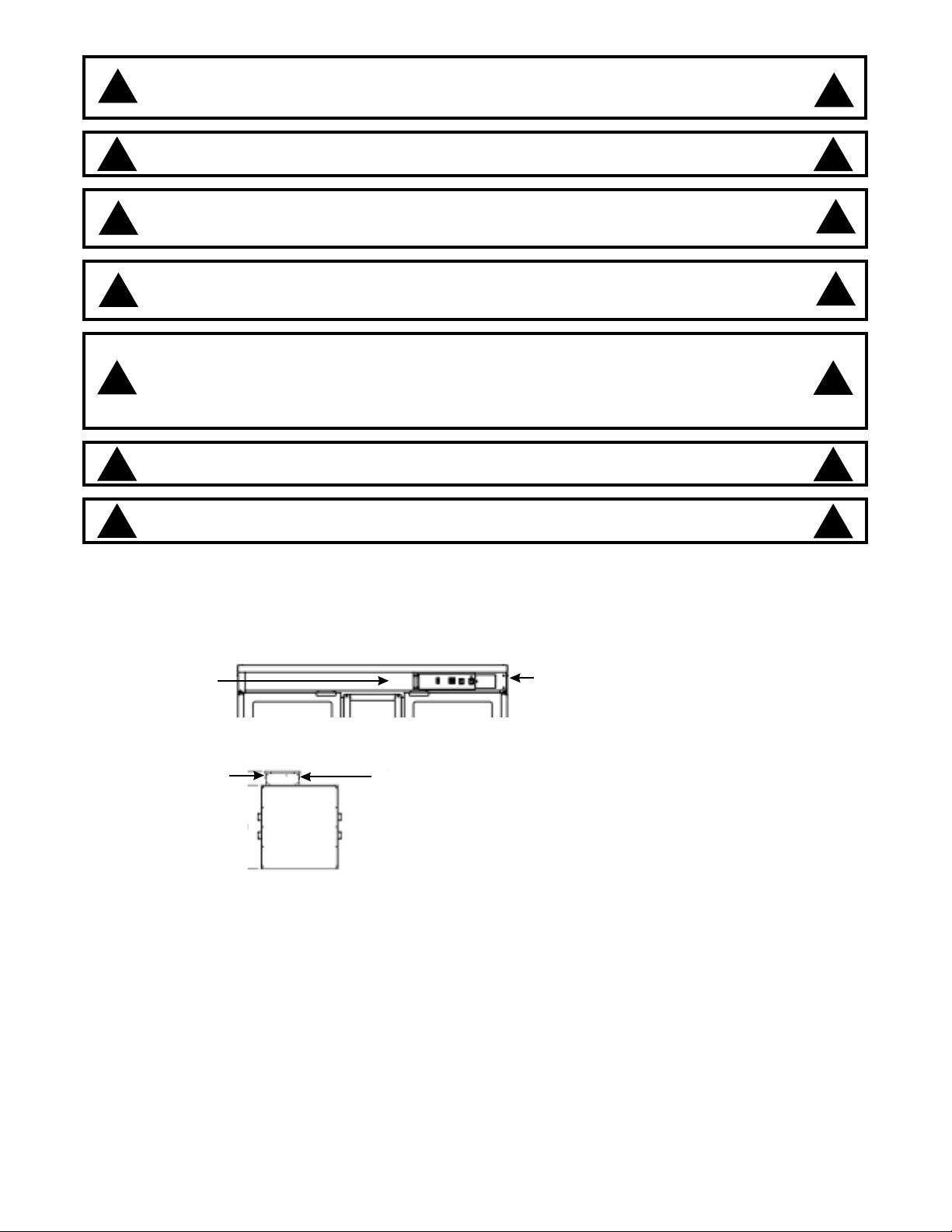
The serial number locations are as follows:
!
KOOP60B data label is next to the control panel at the back of the storage shelf.
Serial Number
!
KOOP60C data label is on the back of the control housing located at the top of the unit.
Control Housing
Always have the serial number of your unit available when calling for parts or service. A
complete list of authorizedAPW Wyott Parts depots is included with the equipment.
Serial Number
Control Panel
RECEIVING AND INSPECTING THE EQUIPMENT
Even though most equipment is shipped crated, care should be taken during unloading so the equipment is
not damaged while being moved into the building.
NOTE: Equipment must be kept dry!
1. Visually inspect the exterior of the package and skid or container. Any damage should be noted and
reported to the delivering carrier immediately.
2. If damaged, open and inspect the contents with a representative of the carrier present.
3. In the event that the exterior is not damaged, yet upon opening there is concealed damage to the
equipment, notify the carrier. Notification should be made verbally as well as in written form.
3
4. Request an inspection of the damaged equipment by the shipping company. This should be done
within ten days from receipt of the equipment.
5. Freight carriers can supply the necessary damage forms upon request.
6. Retain all crating material until an inspection has been made or waived.
SPECIFICATIONS
Electrical Ratings:
KOOP60B: 208V 3 PH L1 — 15.4 A L2 — 13.0 A L3 — 24.6A
240V 3 PH L1 — 13.33 A L2 — 11.33A L3 — 21.4A
KOOP60C: 208V3 PH W/NEUTRAL L1 — 15.7 A L2 — 23.3 A L3 — 18.2A N — 2.5 A
240V 3 PH W/NEUTRAL L1 — 13.6A L2 — 20.2A L3 — 16.1 A N— 2.5 A
Safety Precautions:
CAUTION: Installation and start-up should be performed by a qualified installer (i.e. service
agent) who has thoroughly read, understands and follows these instructions. If you have
questions concerning the installation, operation, maintenance or service of this product,
!
write Technical Service Department APW Wyott Foodservice Equipment Company, P. O.
Box 1829, Cheyenne, WY 82003.
CAUTION: Before installing and operating this equipment, be sure everyone involved in its
operation is fully trained and awareof all precautions. Accidents and problems can result
!
from a failure to follow fundamental rules and precautions.
!
!
Handle Trays
Sold Separately
Packaging
Storage
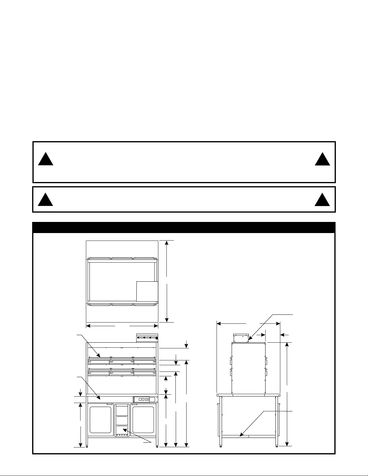
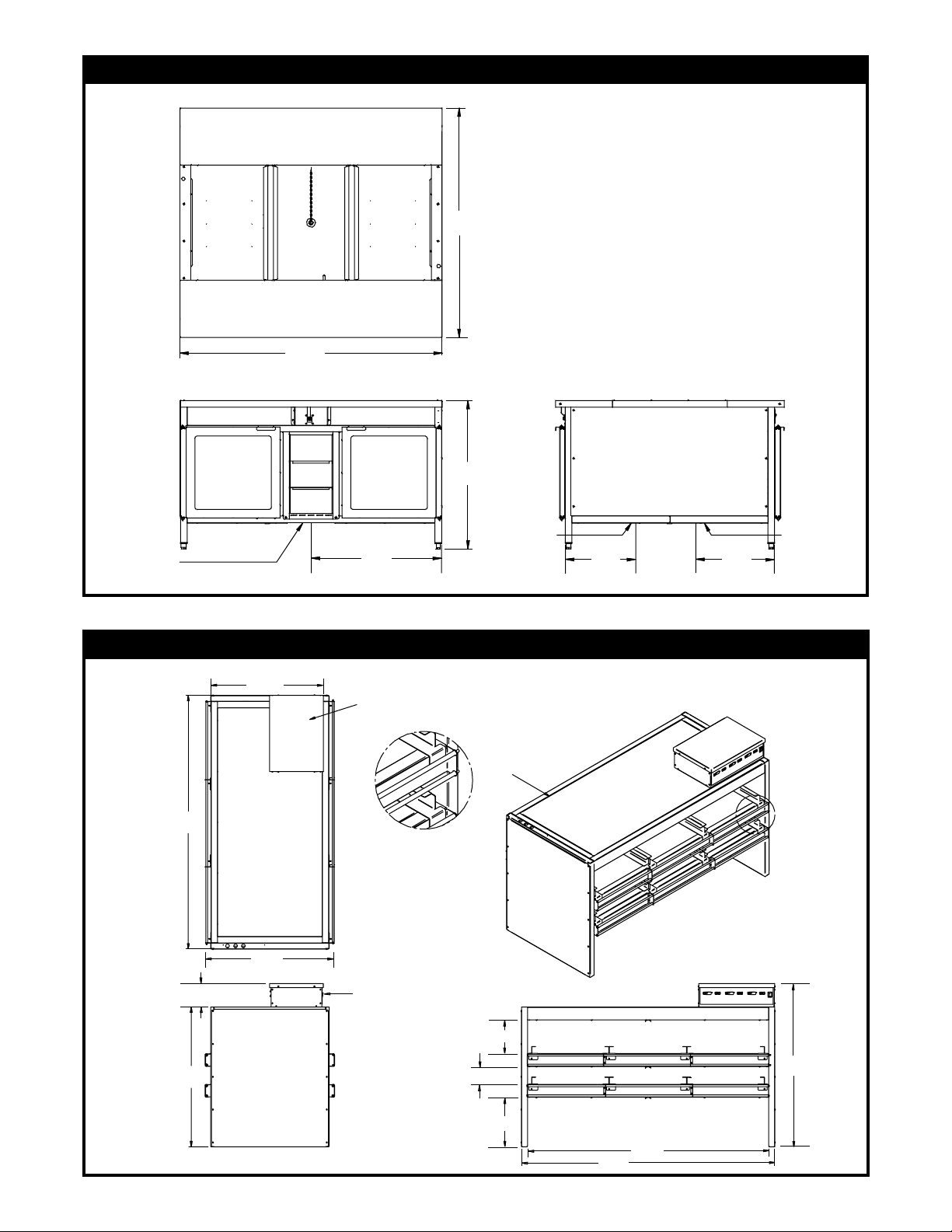
KOOP60B & KOOP60C TOTAL UNIT DIMENSIONS
52.50
52.50
4.12
28.3
60.00
8.0
4.25
11.75
56.00
48.75
34.00
Upper Section
Power
12.25
67.00
Base Section
Power
Packaging/Storage
4
Electrical,
Water
Inlet & Drain
Connections
KOOP60B, BASE UNIT DIMENSIONS
52.5
60.0
34.0
Electrical
Connection
29.0
13.0
Water
Inlet & Drain
Connections
14.0
59.82
5.56
33.00
KOOP60C, SHELF UNIT DIMENSIONS
28.00
30.31
Electrical
Connection
Flush on Top
Detail “A”
Electrical
Connection
8.0
4.25
“A”
38.56
5
11.75
60.0
57.0
INSTALLATION INSTRUCTIONS
1. Check to make sure both sections of the unit are on site, and all parts are there and in good condition.
2. Check units to make sure that they are compatible with the electrical power available in the store. The
KOOP60B base unit requires a 208 volt, 3 phase, 30 AMP (or 240V 3 phase) circuit, power to be
supplied from a floor junction box. The KOOP60C upper shelf unit requires a 208 volt,
Neutral
box.
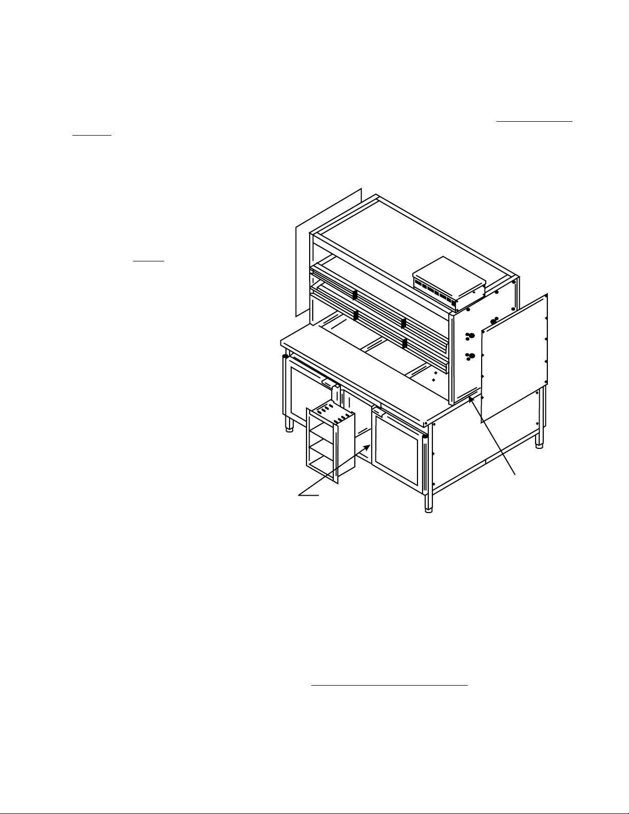
3. Assemble shelf unit to base unit. The
side panels of the shelf unit must be
removed so that the shelves can be
anchored to the base unit. This should
be done before the unit is placed into
the pack line. The side panels are to be
replaced before installing units into the
pack line. , moving the units
should be done with the help of a lift.
Sliding the units may cause the base
frame to be pushed out of square.
Once the unit is in place, level unit and
base legs must be square with the top.
The base must be square for the doors
to close properly.
4. Make all electrical connections to the
base and shelf unit. Access to the base
wiring J-box can be obtained by
removing the four screws securing the
lower packaging shelves and removing
the shelving unit on the control panel
side. Access to the upper shelf units
wiring connections can be obtained by
removing the top cover from the control
box. Please replace all covers before
energizing the units.
5. Make both the water fill connection and
the drain connection. These are to be
done under the unit, opposite the
control panels.
, 30 AMP (or 240V 3 phase with a neutral) circuit, power to be supplied from a ceiling junction
NOTE
Electrical Connection
Base. 4 Screws per Side.
3 phase with a
Screw Locations to
Anchor Shelf Unit to
INSTALLATION CHECK LIST
!
Before powering up the base or shelf section, make sure all cover panels, packaging bins and guards
are in place.
KOOP60B Check List:
!
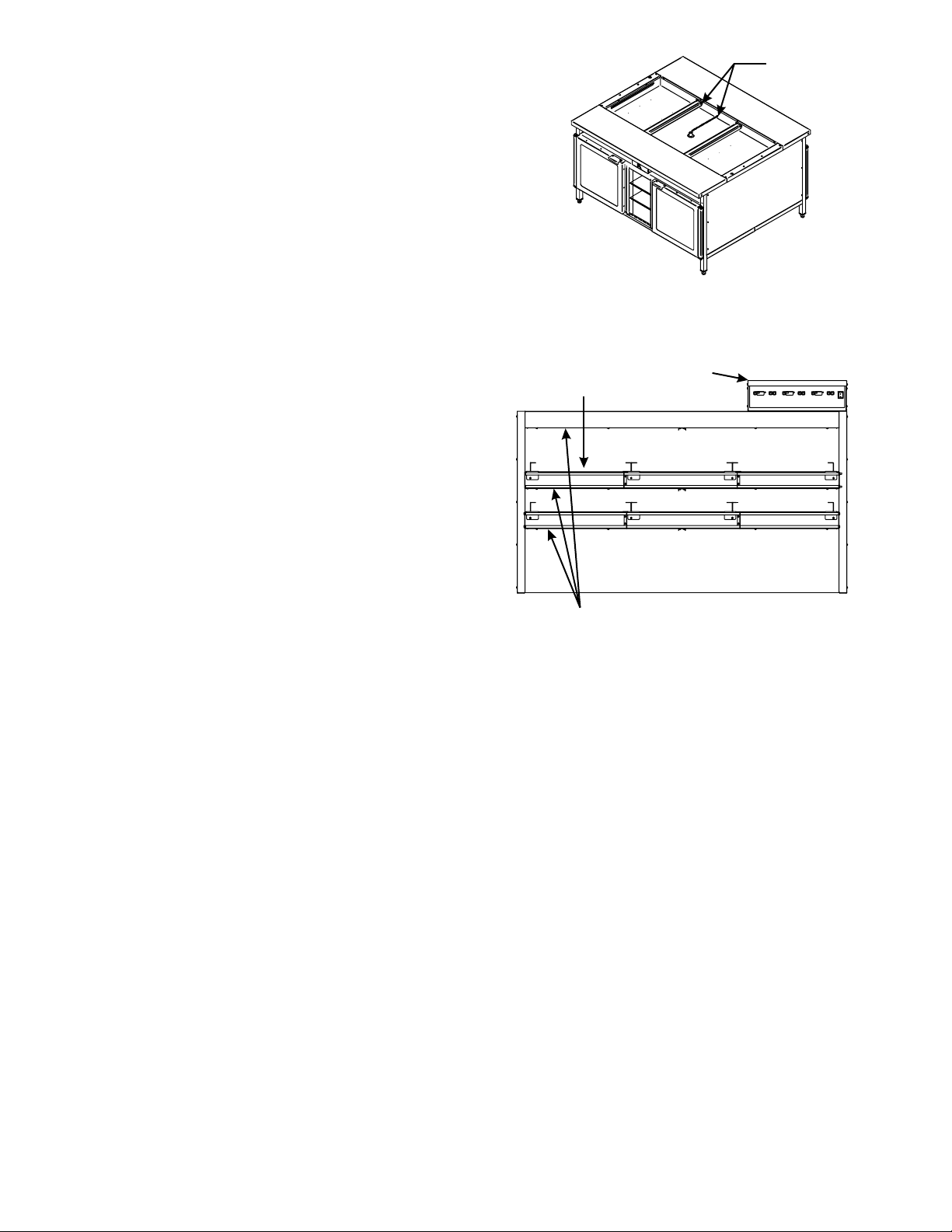
Make sure that the drain standpipe is in place. before turning on the
power to the base unit.
!
Turn on both base unit power switches located on the control panel. There is a power switch for the
water well and a power switch for the base storage units. A power indicator light over the water well
switch will illuminate and the circuit board will activate and display base cabinet temperatures for the
base unit power switch.
Fill the water pan with water
6
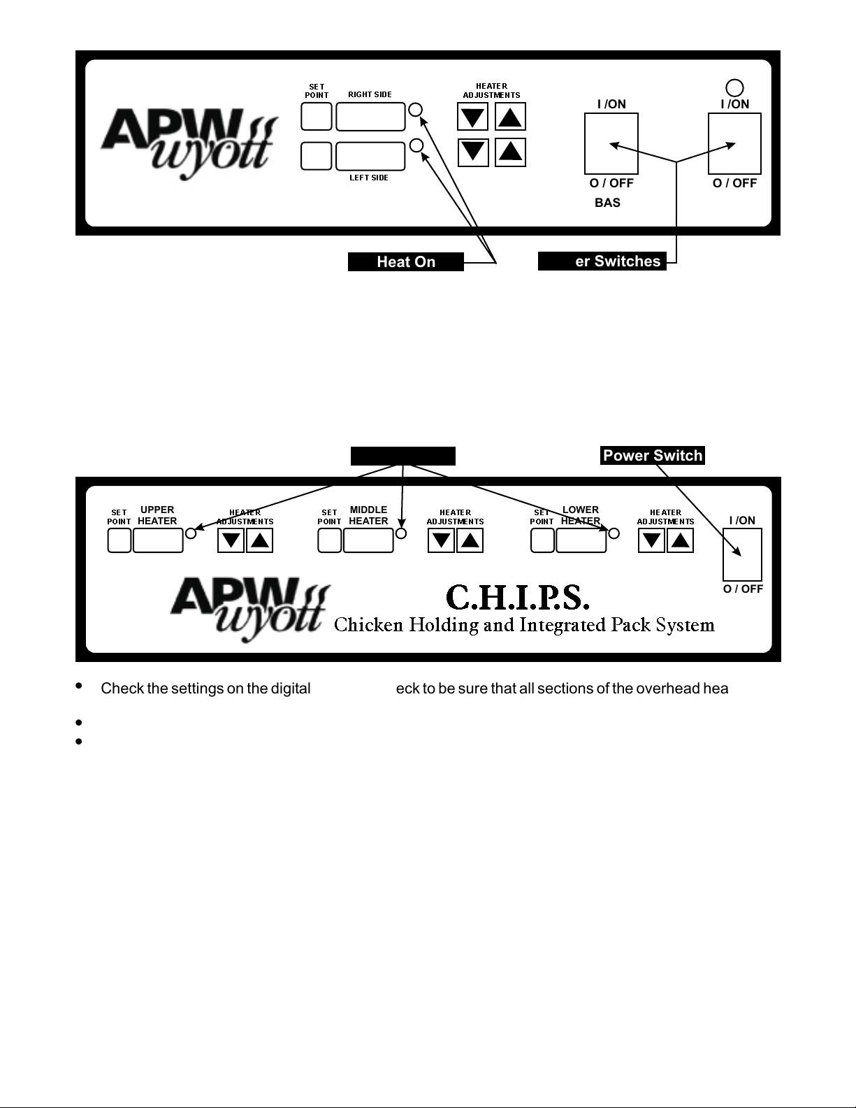
SET
POINT
RIGHT SIDE
HEATER
ADJUSTMENTS
I/ON
I/ON
LEFT SIDE
BASE STORAGE
TEMPERATURES
Heat On
!
Check the settings on the digital displays. Check to be sure that there is heat in the base units. Check
Power Switches
O/OFF
BASE
STORAGE
O/OFF
WATER
the water well to be sure that the water is heating.
!
Check the doors on the storage unit to make sure that they are closing and latching properly.
KOOP60C Check List:
!
Make sure that all covers and side panels are in place before turning on the power to the over shelf unit.
!
Turn on power switch located on the control housing. There is only one power switch for the entire upper
unit. Once power is supplied to this section, the circuit boards will activate and display temperatures.
Power Switch
LOWER
HEATER
ADJUSTMENTS
SET
POINT
UPPER
HEATER
HEATER
ADJUSTMENTS
SET
POINT
Heat On
MIDDLE
HEATER
HEATER
ADJUSTMENTS
SET
POINT
HEATER
HEAT
I/ON
C.H.I.P.S.
Chicken Holding and Integrated Pack System
!
Check the settings on the digital displays. Check to be sure that all sections of the overhead heaters are
heating.
!
Check all light bulbs; the bulbs in this unit are 25 watts @ 120 volts.
!
Check that all pan slides are in place and anchored.
OPERATION INSTRUCTIONS
Once the unit has been properly installed, operation of the unit is as follows:
Base Unit Operations:
!
The Base unit must be filled with water before applying power to the unit. To fill the well with water, turn
the valve located on the customer side (opposite side from the control panels) to the “fill” position. This
is just an “On-Off” valve and must be monitored or water will continue to flow out of the
overflow/standpipe and the required water temperature will never be met.
!
The thermostat for the water temperature is pre-set at the factory. However, if an adjustment is required,
the thermostat knob is located behind the small rectangular cover. The initial setting for this thermostat
is “7-1/2”.
!
Power for the water well is supplied through the right hand switch on the control panel.
!
Power for the heated base units is supplied through the left hand switch on the control panel.
O / OFF
7
!
The digital thermostat for the heated base unit is
set at the factory for 180° F. To check this setting
press the “Set Point” button beside the digital
display. If for some reason this setting must be
changed, press and hold the “Set Point” button
until there is a beep and the display starts to flash,
then use the “Heater Adjustment” buttons to
change the temperature setting. Once the new
setting is displayed, a five second wait will put the
board back into the operation mode.
Over Shelf Unit Operations:
!
The digital thermostats for the heated storage
shelves are set at the factory. For the upper
heaters the set point is 325° F., for the middle
heaters the set point is 190° F., and for the lower
heaters the set point is 410° F. To check this
setting press the “Set Point” button beside the
digital display. If for some reason this setting must
be changed, press and hold the “Set Point” button
until there is a beep and the display starts to flash,
then use the “Heater Adjustment” buttons to
change the temperature setting. Once the new
setting is displayed, a five second wait will put the
board back into the operation mode.
!
Power for the heated storage shelves is supplied
through the switch on the right side of the control
panel. This switch also supplies power to the shelf
lighting.
Handle Trays
Sold
Separately
Heaters
Water Well
&
Plug
Control
Housing
Upper
Middle
Lower
TEMPERATURE ADJUSTMENT INSTRUCTIONS
This unit was set at the factory with these settings; Upper unit, upper heaters 325° F.
Upper unit, middle heaters 190° F.
Upper unit, lower heaters 410° F.
Base unit, water heaters 7-1/2
Base unit, storage heaters 180° F.
If for some reason these temperature settings need to be changed, follow this procedure:
!
The water well thermostat is located behind the rectangular cover on the lower control panel. The dial is
marked 1-10 with 10 being the hottest. After adjusting this thermostat, please replace the rectangular
cover to help eliminate accidental adjustment of the thermostat.
!
The digital thermostats are located on the upper and lower control panels. These controls allow
independent temperature adjustment for each shelf or storage area. To increase or decrease the
temperature:
1. Press and hold the desired zone key, marked “Set Point” to the left of the digital display, for five
seconds.
2. Set Point temperature is displayed and flashing.
3. Adjust set point using the up/down arrow keys to the right of the digital display.
4. To accept, either press the “Set Point” key again, or changes will be accepted with a five second
timeout.
8
 Loading...