

Page 1
R
INSTALLATION AND OPERATING INSTRUCTIONS
KFC HOT WELL AND HEATED STORAGE TABLES
Model: K46HS
IMPORTANT FOR FUTURE REFERENCE
Please complete this information and retain this manual for the life of the equipment. For
Warranty Service and/or Parts, this information is required.
Model Number Serial Number Date Purchased
WARNING: Improper installation, operation, service or maintenance can cause
property damage, injury or death. Utility location is CRITICAL. Read and understand
!
these instructions thoroughly before positioning, installing, maintaining or servicing
this equipment.
Y
A
B
D
E
T
C
E
T
1
O
R
YEAR
P
LIMITED
W
A
N
R
A
R
!
P
W
/
W
Y
O
T
T
S
Y
T
SANITATION
S
I
F
S
I
E
A
L
C
D
P/N 8806315 10/08
APW WYOTT Foodservice Equipment Company
P.O. Box 1829
Cheyenne, WY 82003
+1 (307) 634-5801 Phone +1 (800) 752-0863 Toll Free
+1 (307) 637-8071 Fax www.apwwyott.com
1
Page 2
GENERAL INFORMATION
THIS MANUAL SHOULD BE RETAINED FOR FUTURE REFERENCE
Congratulations on your purchase of APW Wyott Modular Assembly Pack Station. APW Wyott takes pride
in the design and quality of our products. When used as intended and with proper care and maintenance,
you will experience years of reliable operation from this equipment. To ensure best results, it is important
that you read and follow the instructions in this manual carefully.
Before installing and operating this equipment be sure everyone involved in this operation is fully trained
and is aware of all precautions. Accidents and problems can result by a failure to follow fundamental rules
and precautions.
The following words and symbols, found in this manual, alert you to the hazards to the operator, service
personnel or the equipment. The words are defined as follows.
DANGER: This symbol warns of imminent hazard which will result in serious injury or
death.
!
WARNING: This symbol refers to a potential hazard or unsafe practice, which could result
in serious injury or death.
!
CAUTION: This symbol refers to a potential hazard or unsafe practice, which may result in
minor or moderate injury or product or property damage.
!
NOTICE: This symbol refers to information that needs special attention or must be fully
understood even though not dangerous.
!
SAFETY PRECAUTIONS
CAUTION: These models are designed, built, and sold for commercial use. If these
models are positioned so the general public can use the equipment make sure that
cautions, warnings, and operating instructions are clearly posted near each unit so that
!
anyone using the equipment will use it correctly and not injure themselves or harm the
equipment.
WARNING: Improper installation, adjustment, alteration, service or maintenance can
cause property damage, injury or death. Read installation, operating and maintenance
!
instructions thoroughly before installing or servicing this equipment.
!
!
!
!
!
!
NOTICE: Install according to the spacing requirements listed in the installation section of
this manual. We strongly recommend having a competent professional install the
!
equipment. Such a person should be familiar with local gas regulations. A gas company
representitive should approve the completed installation.
WARNING: For your safety do not store or use gasoline or other flammable vapors or liquids in the
vicinity of this or any other appliance. Keep the area free and clear of combustibles. (See ANZI
!
Z83.14B, 1991)
NOTICE: Instructions to be followed if anyone smells gas should be posted in a prominent place.
These may be obtained from the gas supplier.
!
WARNING: The appliance and its individual shut-off valve must be disconnected from the
gas supply piping system during any pressure testing of that system at test pressures in
!
excess of 1/2" psig (3.45kpa).
2
!
!
!
!
Page 3
WARNING: The appliance must be isolated from the gas supply piping system by closing
its manual shut-off valve during any pressure testing of the gas supply piping system at
!
test pressures equal to or less than 1/2" psig (3.45kpa).
NOTICE: Maintenance and repair should be handled by a factory authorized agent.
!
Before doing any maintenance or repair, contact APW/Wyott.
!
!
WARNING: This product is intended for commercial use only. Not for household use Retain this
manual for future reference Oven must be kept clear of combustibles at all times
!
WARNING: SHOCK HAZARD - Do not open any panels that require the use of tools.
!
WARNING: Keep the appliance free and clear from all combustible substances. In the event of gas
odor, shut unit down at the main shutoff valve and contact the local gas company or gas supplier for
!
service.
TABLE OF CONTENTS
SECTION
1
2
ITEM
General Information
Safety Precautions
Installation Check List
Installation
!
!
!
PAGE
2
2
4
4
3
4
5
6
7
Utilities, Electrical & Plumbing
Electrical Connections
Wiring Diagram
Table Wiring Instructions
Specifications
Operation & Maintenance
A Cleaning/Maintenance
B Maintenance
C Heated Table Operating Instructions
D Cold Table Operating Instructions
Troubleshooting & Equipment Specifications
Parts List w/Exploded View
Warranty
5
5
5
6
6
7
7
7
7
8
8
9
12
3
Page 4
1. INSTALLATION CHECK LIST
Examine Equipment for Damage
All containers should be examined for damage before and during unloading. The freight carrier has
assumed responsibility for its safe transit and delivery. If equipment is received damaged, either apparent
or concealed, a claim must be made with the delivering carrier.
1. Apparent damage or loss must be noted on the freight bill at the time of delivery. The carrier
representative (Driver) must sign the freight bill. If this is not done, the carrier may refuse the
claim. The carrier can supply the necessary forms.
2. Concealed damage or loss if not apparent until after the equipment is uncrated; a request for
inspection must be made to the carrier within 15 days. The carrier should arrange an inspection. Be
sure to hold all contents and packaging material.
NOTICE: Installation and start-up should be performed by a qualified installer who
!
thoroughly read, understands and follows these instructions.
NOTICE: If you have questions concerning the installation, operation, maintenance or
service of this product, write Technical Service Department APW WYOTT Foodservice
!
Equipment Company, P.O. Box 1829, Cheyenne, WY 82003.
!
!
IMPORTANT: Check Store Layout for Placement and Location of table.
!
IMPORTANT: Check Store Layout for Placement and Location of Utilities.
!
NOTE: All electrical connections to be hardwired by electrician.
!
!
!
!
2. INSTALLATION
A qualified installer who thoroughly reads, understands and follows these instructions should perform
installation and start-up.
If you have questions concerning the installation, operation, maintenance or service of this product,
Call: APW Wyott Technical Services Department 1-800-752-0863, ask for Technical Service Department Monday through Friday 9AM 6:30PM Eastern Time.
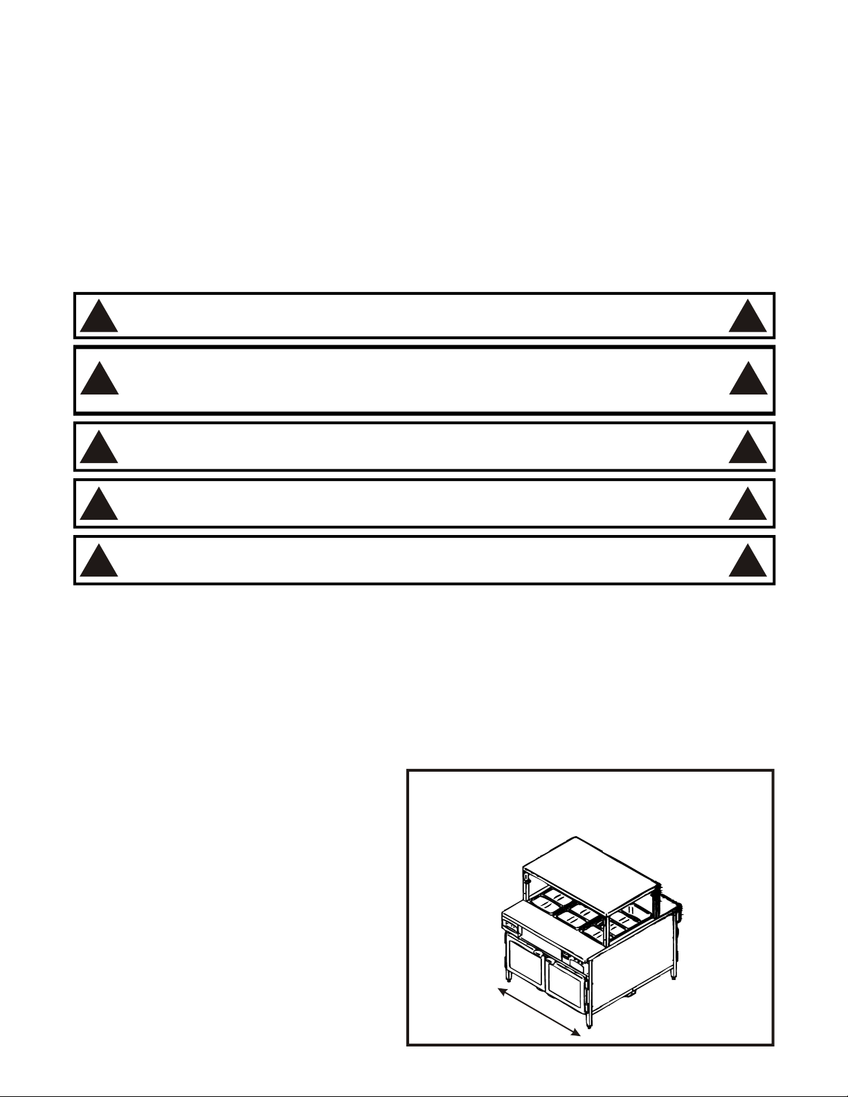
STEP 1. POSITION TABLE
REVIEW STORE LAYOUT FOR EXACT
LOCATION OF TABLE
Plumbing and electrical wiring must run parallel to,
or under center channel. (It must run in the
direction of arrow)
Place the table in the designated area.
Level table by using a level and turning the
footpad on the adjustable legs.
If table is being used in conjunction with other
tables bolt tables together thru holes in corners
of the top using provided hardware. Make sure
tables all face the same direction (control panels
should be on same side).
4
Page 5

Holes for bolting
tables together
Adjust Legs
3. UTILITIES, ELECTRICAL & PLUMBING
WARNING: Check the data plate on this unit before installation. Connect the unit only to
the voltage and frequency listed on the data plate. Connect only to 1 or 3 phase as listed
!
on the data plate.
WARNING: Electrical and grounding connections must comply with the applicable
portions of the national electrical code and/or other local electrical codes.
!
ELECTRICAL CONNECTIONS FOR K46HS
Check the data plate to determine what voltage this
unit is wired for and what voltage service is to be used.
!
!
SUPPLY REQUIREMENT: 208V, 60HZ, 3 Phase, L1 - 21 Amps, L2 - 21 Amps, L3 - 15 Amps
WIRING DIAGRAM K46HS
Red Lead
From
Transformer
Primary Side
Black Lead
From
Transformer
Primary Side
Terminal
#1126030
to Cap
Transformer
Wires
Air Heat
1300W
16
18
208V
Transformer
24V
Splice 1100100
Wire Nut
1196100
22
Hotwell
1800W
21
17
Circuit
2
1
3
Board
4
Red
Black
White
Black
@ Transformer Wires
dR
e
Terminal
#1102214
Hotwell
1800W
29
17
1
2
3
Black
Power
Switch
7
Wire Nut
1196100
Hotwell
1800W
Thermostat
1
2
Indicator
L3
1
2
3
10
Light
11
Power
Switch
Wire Nut
1196100
Wire Nut
1196000
Typical
Thermostat
3
4
Indicator
2
3
13
Light
14
Power
Switch
Wire Nut
1196100
23
L1
L2
5
6
24
25
Thermostat
11
2
3
26
Indicator
Light
27
Power
Switch
Terminal
#1119512
@ Hot Well
& Ground
5
Page 6

TABLE WIRING INSTRUCTIONS
1. Remove the J-Box cover.
2. Select the most appropriate place to bring in your power connections and remove that hole plug.
3. Place a strain relief in the hole selected.
4. Run the incoming power connection leads through that strain relief.
5. Connect the power leads to the appropriate wires.
6. Replace the J-Box cover.
DANGER: Electrical shock can kill. Make sure power has been disconnected at the
source before making these connections.
!
WARNING: Make sure the circuit breaker has been sized correctly for this application.
!
SPECIFICATIONS
46.00
52.50
29.12
!
!
Model
K46HS
Drain
Electrical Connection
Dimensions
W
46
D
52.5
50.09
50.1
50.17
34.00
Drain & Electrical box, centered on table
Electrical
H
V
208 6700
W
A
33
6
Weight
545 Lb. 91
Cube
F.O.B.
Cheyenne, WY
Page 7

4. OPERATION AND MAINTENANCE
CLEANING/MAINTENANCE
Initial Cleaning:
Prior to operating your new unit, thoroughly wash the well pan(s) and exterior with a mild detergent or soap
solution. Wash table top and frame in the same fashion. Do not use Abrasive cleaners since this might
damage the cabinet finish. If stainless steel surfaces become discolored, scrub by rubbing only in the
direction of the finish grain. Never use vinegar or corrosive cleaner. Do not use chlorine-based
cleaners. Do not use steel wool, steel wool may leave particles that can rust and cause pitting.
Cleaning:
1. Always turn off and allow units to cool completely before cleaning. Clean thoroughly, before the first
use.
2. Daily remove any pans or food containers and wash thoroughly. If any cleaners are used, rinse
thoroughly in warm water to remove any residue.
3. Daily wipe down all table surfaces with mild detergent or soap solution or use a stainless steel
cleaner. Note: If stainless steel cleaner is used, wipe surfaces with warm water to remove any
cleaner residue before using.
4. Daily pull carts from under table and mop this area.
5. At least weekly remove articles from shelving carts and clean these carts.
MAINTENANCE
Never clean any electrical unit by immersing it in water. Turn unit off before cleaning surface.
STAINLESS STEEL: To remove normal dirt or product residue from stainless steel, use ordinary soap and
water with or without detergent applied with a sponge or cloth. Dry thoroughly with a clean cloth. Never use
vinegar or corrosive cleaner. Do not use chlorine-based cleaners.
To remove grease and food splatter or condensed vapors that have baked on the equipment, apply
cleaners to a damp cloth or sponge and rub cleaner on the metal in the direction of the polish lines on the
metal. Rubbing cleanser as gently as possible in the direction of the polish lines will not mar the finish of the
stainless steel. NEVER RUB WITH A CIRCULAR MOTION. Soil and burned on deposits, which do not
respond to the above procedure, can usually be removed by rubbing the surface with scouring pads for
stainless steel.
DO NOT USE ordinary steel wool, as any particles left on the surface will rust.
NEVER USE a wire brush, steel or abrasive scouring pads (except stainless), scraper, file or other steel
tools. Surfaces which are marred, collect dirt more rapidly and become more difficult to clean. Marring also
increases the possibility of corrosive attack.
NEVER USE any corrosive cleaner or vinegar.
USE ONLY cleaners approved for stainless steel.
NEVER USE cleaning solvents with hydrocarbon or chloride base.
TURN OFF all power to equipment before cleaning.
HEATED TABLE OPERATING INSTRUCTIONS
Apply power to the unit. Turn on the red power switch to turn on the bottom heat. The switch will illuminate
indicating there is power to the unit. The unit has been calibrated at the factory to hold product 160°F to
180°F. Wait about 30 to 45 minutes for the unit to heat. If product is too cold or too warm adjust appropriate
infinite switch. The infinite switch knobs are located behind the removable panel. Remove single screw on
the removable panel to access the adjustment knobs. The factory set point for the overhead heaters is
setting 5. Turn knob to a higher number for a warmer product and to a lower number for a cooler product.
Replace the removable panel so the setting is not accidentally moved from it's setting. Wait 30 to 45
minutes to determine of the product is at an acceptable temperature. NOTE: Holding foods below 140°F
can cause potential contamination problems.
7
Page 8

! Product not hot enough. Turn both infinite knobs to a higher number.
! Product too hot. Turn both infinite switch knobs to a lower number.
! Product drying out before reaching hold time limit. Turn the overhead heater infinite switch knob to a
lower number. This is the knob toward the center of the table. NOTE: After turning the overhead
heater down, the internal temperature of the product may become cooler. If this is too cool, you can
compensate by turning the bottom heat higher.
This unit is not intended to hold uncooked or unpreserved foods.
1. Trained personnel should operate all food service equipment.
2. Never hold food hot food below 140°F
COLD TABLE OPERATING INSTRUCTIONS
Apply power to the unit. Turn on the red power switch to turn on the refrigeration compressor. The switch will
illuminate indicating there is power to the unit. The unit has been calibrated at the factory to hold product
between 34°F and 40°F. Wait about 30 to 45 minutes for the unit to stabilize. If product is too cold or too
warm, adjustments can be made to the pressure switch. The pressure switch is located inside of the
compressor housing and should only be adjusted by a factory authorized service agent. NOTE: Holding
refrigerated products above 40°F can cause potential contamination problems.
5. TROUBLESHOOTING & EQUIPMENT SPECIFICATIONS
GENERAL TROUBLESHOOTING
PROBLEM PROBABLE CAUSE CORRECTIVE ACTION
Unit fails to operate No power Make sure the power switch is on.
Make sure the unit is connected to a live power source.
Loose connection Place the power switch in the "OFF" position and disconnect power from
unit. Warning: Failure to do so may result in electrical shock. Check and
tighten all connections.
Open circuit breaker or fuse Reset breaker or fuse.
Faulty cord or plug Place the power switch in the "OFF" position and disconnect power from
unit. Warning: Failure to do so may result in electrical shock. Replace cord
or plug
Faulty power switch Place the power switch in the "OFF" position and disconnect power from
unit. Warning: Failure to do so may result in electrical shock. Replace
power switch.
Holding temperature Draft on product Remove draft
too low, (heated unit) Set point too low Refer to the Operations section for the adjustment procedure for this
particular unit.
Heater not working Place the power switch in the "OFF" position and disconnect power from
unit. Warning: Failure to do so may result in electrical shock. Replace
heater.
Faulty thermostat or Place the power switch in the "OFF" position and disconnect power from
infinite switch unit. Warning: Failure to do so may result in electrical shock. Replace
defective component.
Holding temperature Set point too high Refer to the Operations section for the adjustment procedure for this
too high, (heated unit) particular unit.
Faulty thermostat or Place the power switch in the "OFF" position and disconnect power from
infinite switch unit. Warning: Failure to do so may result in electrical shock. Replace
defective component.
Slow cooling Dirty condensor coil Clean condenser.
(refrigerated unit) Poor air supply Airflow is restricted through compressor compartment or the air is too hot.
Remove restriction or source of heat.
Leak (low on refrigerant) Call APW Wyott certified refrigeration technician.
Condensing unit won't No power Make sure the power switch is on.
run (refrigerated unit) Make sure the unit is connected to a live power source.
Faulty compressor Call APW Wyott certified refrigeration technician.
Evaporator fan won’t Loose connection Place the power switch in the "OFF" position and disconnect power from
run (refrigerated unit) unit. Warning: Failure to do so may result in electrical shock. Check and
tighten all connections.
If all of the above are correct & the unit still does not work, call an APW Wyott Authorized Service Agency.
8
Page 9

NOTICE: Only a qualified
operation of this electricaland refrigerated equipment should perform service work.
!
Contact the Authorized Service Agency for reliable service, dependable advise or other
assistance and for genuine factory parts.
A current listing of all authorized APW Wyott Authorized Parts and Service Distributors is included with
these units. In the absence of this list call the APW Wyott 24-hour Service Hot line at 1-800-733-2203. This
will give access to the nearest Authorized APW Wyott Parts & Service Distributor.
WARRANTY WILL BE VOID AND THE MANUFACTURER IS RELIEVED OF ALL LIABILITY IF:
1. Service work is performed by other than an APW Wyott Authorized Service Agency.
2. Other than Genuine APW Wyott replacement parts are installed.
technician who is experienced in and knowledgeable with the
!
6. PARTS LIST w/EXPLODED VIEW
EXPLODED VIEW K46HS - HOT WELL TABLE w/STORAGE
5
2
61
21
48
17
1
4
44
58
60
74
35
71
18
11
66
69
56
45
14
3
52
67
70
16
37
32
10
63
9
Page 10

Item
P/N
PARTS LIST K46HS - HOT WELL TABLE w/STORAGE
Description
Quan
Item
P/N
Description
Quan
1
2
3
4
5
6
7*
8*
9
10
11
12*
13*
14
15*
16
17
4882110
4882101
8656500
4839260
4882154
4882133
4882161
8173000
8978400
8655000
8511900
4882107
4882121
4882129
2092401
4882145
3028272
Weldment, Frame K46HS
Top, Table
Foot 1.5 Sq.
Adapter Pan 4/3 Well (4) 1/3 Size Pans
Over Shelf, 46 Hot Table
Cover, Fan Mount Side
Bottom Panel
Weldstud, 10-32 x 1/2 Non-flanged
Bushing, 7/8 Snap Heyco
Hinge, 215
Washer, Flat 3/8
Shelf, Under Counter
Panel, Inner Cover
Panel, Outer Cover
Adapter, Copper CxM 1/2
Door Assy, R.H.
Hotwell 4/3 208V w/Drain, 72" Cap
15
39*
40*
41*
42*
43*
44
45
46*
47*
48
49*
50*
51
52
53*
54*
55*
4871214
4871219
4882159
4882137
4882158
4882135
8655000
4871222
4882156
4882140
4882157
8417100
4882161
4882162
4882136
8505300
1
1
4
3
1
2
2
1
4
8
1
2
2
3
2
3
Tube, Drain 1/2" x 2"
Tee 3/4 x 3/4 x 1/2 Copper
Handle, Drain
Weldment, Drain Yoke
Support, Drain Handle
Weldment, Control Panel
Hinge, 215
Cap, 3/4" Copper
Extension Rod, 3"
Door Assy, L.H.
Cover, Drain Lever
Nut, Hex 10-32
Panel, Bottom Motor Cover
Panel, Bottom Fill
Support Hinge Anchor
Flat Washer #10
Panel, Control Fill
3
3
1
1
1
1
4
1
1
2
1
16
1
2
4
10
1
18
19*
20
21
22*
23
24*
25
26*
27
28
29
30
31*
32
33*
34*
4882178
4882108
4882122
4882106
4871221
4882109
4882132
4882120
4882131
4882124
4882111
4882113
4882112
4882125
1305610
4871213
4871212
Tong Holder, R.H.
Angle, Retaining
Panel, Upper Inner Cover
Shelf, Control Side
Elbow, 90°, 3/4 Copper
Angle, Retaining
Tube, Drain 3/4" x 19"
Assy, Heater
Tube, Drain 3/4" x 9.5"
Pan Cover
Panel, Air Duct Top
Panel, Air Return
Panel, Air Duct Center
Weldment, Pan Slide
Switch, Rocker
Tube, Drain 3/4" x 2"
Tube, Drain 3/4" x 13"
56
57*
58
59*
60
61
62*
63
64*
65*
66
67
68*
69
70
71*
72
4882149
1619000
8130000
8353000
4882177
4824275
8169700
8184500
8982100
8442000
1610950
8969600
8244700
1610650
8134900
8400100
2
4
2
1
2
2
1
1
1
1
1
2
1
4
4
3
2
Insulation Package
Plug Beauty 1" Chrome
8-32 x 3/8
Pop Rivet
Holder, Tong
Holder, Liners
10-32 x 3/8 Screw
Screw, FH 10-32 x 1
Bushing, Bronze
Nut, Hex 3/8-16 S/S
J-Box Cover
Bushing, Snap Heyco
Hex Hd 3/8-16 x .750
J-Box
8-32 x 3/8 Tr Hd
Nut, Hex #6-32
1
1
100
70
2
2
26
40
2
1
5
1
1
6
1
1
6
35
36
37
38*
4845078
4882130
280712
4871223
Label, Temperature Control
Weldment, Pan Support
Plate Cover
Valve, 3/4 Copper Ball, Sweated Ends
73
1
74
4
75
1
76
1
* = Not Shown
10
4880217
1451700
782162
Plate, SSR Heat
Relay, SS
1
1
1
1
Page 11

Notes:
11
Page 12

7. APW WYOTT EQUIPMENT LIMITED WARRANTY
APW Wyott Foodservice Equipment Company warrants it's equipment against defects in materials and workmanship, subject to the
following conditions:
This warranty applies to the original owner only and is not assignable.
Should any product fail to function in its intended manner under normal use within the limits defined in this warranty, at the option of
APW Wyott such product will be repaired or replaced by APW Wyott or its Authorized Service Agency. APW Wyott will only be
responsible for charges incurred or service performed by its Authorized Service Agencies. The use of other than APW Wyott
Authorized Service Agencies will void this warranty and APW Wyott will not be responsible for such work or any charges associated
with same. The closest APW Wyott Authorized Service Agent must be used.
This warranty covers products shipped into the 48 contiguous United States, Hawaii, metropolitan areas of Alaska and Canada. There
will be no labor coverage for equipment located on any island not connected by roadway to the mainland.
Warranty coverage on products used outside the 48 contiguous United States, Hawaii, and metropolitan areas of Alaska and Canada
may vary. Contact the international APW Wyott distributor, dealer, or service agency for details.
Time Period
One year for parts and one year for labor, effective from the date of purchase by the original owner. The Authorized Service Agency
may, at their option, require proof of purchase. Parts replaced under this warranty are warranted for the un-expired portion of the
original product warranty only.
Exceptions
In all cases, parts covered by extended warranty will be shipped FOB the factory after the first year.
Portable Carry In Products
Equipment weighing over 70 pounds or permanently installed will be serviced on-site as per the terms of this warranty. Equipment
weighing 70 pounds or under, and which is not permanently installed, i.e. with cord and plug, is considered portable and is subject to
the following warranty handling limitations. If portable equipment fails to operate in its intended manner on the first day of
connection, or use, at APW Wyott's option or its Authorized Service Agency, it will be serviced on site or replaced.
From day two through the conclusion of this warranty period, portable units must be taken to or sent prepaid to the APW Wyott
Authorized Service Agency for in-warranty repairs. No mileage or travel charges are allowed on portable units after the first day of use.
If the customer wants on-site service, they may receive same by paying the travel and mileage charges. Exceptions to this rule: (1)
countertop warmers and cookers, which are covered under the Enhanced Warranty Program, and (2) toasters or rollergrills which have
in store service.
Exclusions
The following conditions are not covered by warranty:
If the equipment has been changed, altered, modified or repaired by other than an Authorized Service Agency during or after the
warranty period, then the manufacturer shall not be liable for any damages to any person or to any property, which may result from the
use of the equipment thereafter.
This warranty does not cover services performed at overtime or premium labor rates. Should service be required at times which
normally involve overtime or premium labor rates, the owner shall be charged for the difference between normal service rates and such
premium rates. APW Wyott does not assume any liability for extended delays in replacing or repairing any items beyond its control.
In all cases, the use of other than APW Wyott Authorized OEM Replacement Parts will void this warranty.
This equipment is intended for commercial use only. Warranty is void if equipment is installed in other than commercial application.
Water Quality Requirements
Water supply intended for a unit that has in excess of 3.0 grains of hardness per gallon (GPG) must be treated or softened before
being used. Water containing over 3.0 GPG will decrease the efficiency and reduce the operation life of the unit.
Note: Product failure caused by liming or sediment buildup is not covered under warranty.
“THE FOREGOING WARRANTY IS IN LIEU OF ANY AND ALL OTHER WARRANTIES EXPRESSED OR IMPLIED
INCLUDING ANY IMPLIED WARRANTY OF MERCHANTABILITY OR FITNESS FOR PARTICULAR PURPOSES
AND CONSTITUTES THE ENTIRE LIABILITY OF APW WYOTT. IN NO EVENT DOES THE LIMITED WARRANTY
EXTEND BEYOND THE TERMS STATED HEREIN.”
*Gas/Electric Cookline: Models GCB, GCRB, GF, GGM, GGT, CHP-H, EF, EG, EHP. Three (3) Year Warranty on all
component parts, except switches and thermostats. (2 additional years on parts only. No labor on second or third year.)
*Broiler Briquettes,
*Heat Strips: Models FD, FDL, FDD, FDDL. Two (2) Year Warranty on element only. No labor second year.
*Glass Windows, Doors, Seals, Rubber Seals, Light Bulbs:
*Equipment failure relating to improper installation, improper utility connection or supply and problems due to
ventilation.
*Equipment that has not been properly maintained, calibration of controls, adjustments, damage from improper cleaning
and water damage to controls.
*Equipment that has not been used in an appropriate manner, or has been subject to misuse or misapplication, neglect,
abuse, accident, alteration, negligence, damage during transit, delivery or installation, fire, flood, riot or act of god.
*Equipment that has the model number or serial number removed or altered.
Rock Grates, Cooking Grates, Burner Shields, Fireboxes: 90 Day Material Only. No Labor.
90 Day Material Only. No Labor.
9/05
12
 Loading...