

Aprilaire 50, 51 Installation Manual
Installation Instructions for
Models 50 and 51 Current Sensing Relays
Current Sensing Relays
GENERAL INFORMATION
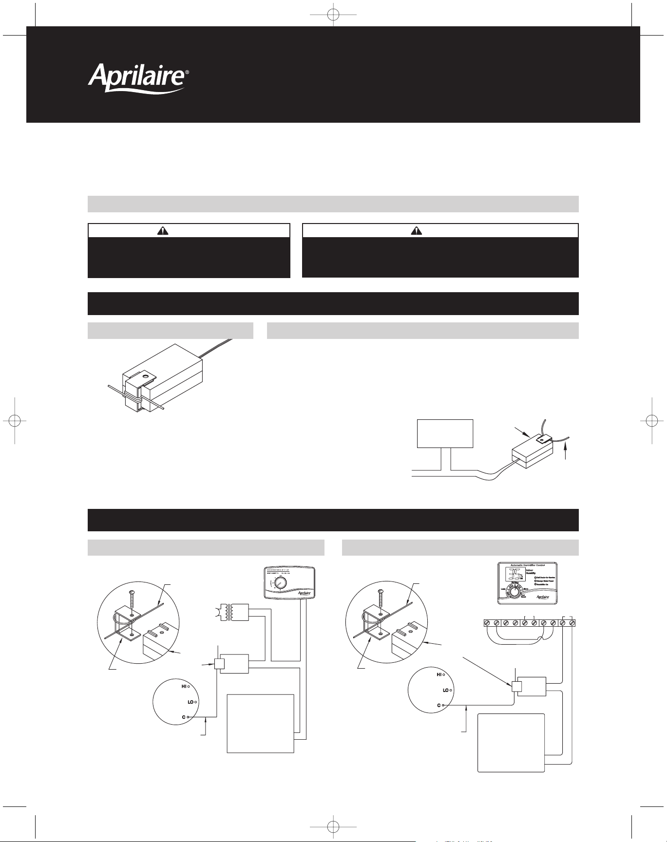
MODEL 50 HUMIDIFIER WIRING DIAGRAMS
READ COMPLETE INSTALLATION INSTRUCTIONS BEFORE STARTING.
GENERAL INSTALLATION PROCEDURES FOR MODELS 50 AND 51 RELAYSMODELS 50 AND 51 RELAY
INSTALLED WITH MANUAL HUMIDIFIER CONTROL INSTALLED WITH AUTOMATIC HUMIDIFIER CONTROL
WARNING
120 volts may cause serious injury from electric shock.
Disconnect power to the furnace before attaching the
Model 50 or 51 Current Sensing Relays.
CAUTION
1. Load must not exceed recommended ratings. (See specifications)
2. Load must be wired in series with relay.
3. Do not power humidifier from furnace blower motor circuit.
1. Disconnect power before installing.
2. The Models 50 or 51 must be located at least 4” from any transformer.
3. Remove the screw from the bracket and place the common wire that will activate the relay
between the bracket and the plastic case.
4. If the current through the common wire is less than 4 amps, wrap it one or more additional
turns around the metal bracket.
5. Replace the metal screw in the bracket.
6. Complete the wiring as shown in the
appropriate diagram.
7. Read the checkout procedure.
8. Relay bracket must not come in contact
with metal.
1. Not approved for directly controlling motors of
safety related applications.
2. Always disconnect power before working on the
Current Sensing Relay or its connected load.
3. Follow all local electrical and safety codes,
the National Electrical Code (NEC), and OSHA
requirements.
90-1251 90-1249
90-908
90-909
10005113_B AA Model 50-51 Install 1/11/08 12:30 PM Page 1
LOAD
24 or
120 VAC
RELAY
COMMON
LEAD
4 Amp. min.
COMMON LEAD
120 VAC
CURRENT
SENSING
FURNACE
BLOWER
MOTOR
RELAY
COMMON
METAL BRACKET
24
VAC
TRANSFORMER
MODEL
50
HUMIDIFIER
METAL BRACKET
NOTE: SET THE WATER PANEL
CHANGE INDICATOR TO THE “OFF”
POSITION WHEN USING THE MODEL
50 CURRENT SENSING RELAY WITH
AUTOMATIC CONTROL.
COMMON LEAD
FURNACE
BLOWER
MOTOR
COMMON
CURRENT
SENSING
RELAY
AUTOMATIC CONTROL TERMINAL STRIP
R C A B ODT CfW/G H
24V
JUMPER WIRES REQUIRED
FOR THE AUTOMATIC DIGITAL
HUMIDIFIER CONTROL ONLY
HUMIDIFIER
MODEL
50

RESEARCH PRODUCTS CORPORATION
P.O. BOX 1467 • MADISON, WI 53701-1467 • PHONE: 608/257-8801 • FAX: 608/257-4357 • www.aprilairecontractor.com
10005113 1.08
B2202490B
MODEL 51 TYPICAL ELECTRONIC AIR CLEANER INSTALLATION
1. Disconnect power before installing.
2. Install the Model 51 on the common wire of the blower motor as
shown in the diagram.
3. Open the main power junction box on the side of the furnace. Run the
leads of the Model 51 relay into the junction box.
4. Connect the leads of the Model 51 relay in series with one of the
electronic air cleaner leads. Connect remaining lead and ground wire of
the electronic air cleaner. The 120 VAC source must be independent of
the furnace blower motor.
5. Check all wire connections, close junction box and restore furnace to
working order. Test proper functioning of the Model 51 by observing
that the air cleaner’s indicator lamp turns on when the blower runs and
turns off when the blower stops.
CHECKOUT PROCEDURES FOR MODELS 50 AND 51 RELAYS
1. Replace all safety devices.
2. Reconnect power to furnace.
3. Activate furnace blower motor.
4. Check load for operation – it should now be operating properly. (Check
indicating lamp or other condition showing the load is receiving power.)
5. Switch off the blower unit. The power to the device should shut off.
6. If the device is activated properly and turns off when the power
through the common wire is removed, installation is complete.
7. If the device is not powered when the blower is turned on then:
• Ensure the device’s ON/OFF switch is ON.
• Recheck all wiring.
• Check line fuses.
• Confirm that four (4) or more amps is flowing through the
common wire. Wrap additional turns around the bracket if
necessary.
SPECIFICATIONS
Model 50 Model 51
Voltage Range 21-24 VAC, 50-60 Hz 100-125 VAC, 50-60 Hz
Sensing Current Minimum of 4.0 amps Minimum of 4.0 amps
Operating Ambient Temperature Range 40°F to 104°F 40°F to 104°F
Dimensions 1” x 1-7/16” x 2-3/4” 1” x 1-7/16” x 2-3/4”
Load Ratings Maximum (12 watts) 0.50 amps Maximum (50 watts) 0.42 amps
Minimum (3 watts) 0.12 amps Minimum (3 watts) 0.03 amps
Case Color Black Yellow
Underwriters Laboratories Recognized Component N/A Yes
90-1264 90-1265
10005113_B AA Model 50-51 Install 1/11/08 12:30 PM Page 2
MODEL
51
BRACKET
BLOWER
MOTOR
COMMON
120 VAC
EAC
120 VAC
120 VAC
to EAC
JUNCTION
MODEL 51
COMMON
WIRE
ELECTRONIC AIR CLEANER
BOX
BLOWER
FURNACE
 Loading...