

Page 1
Service Source
MacBook Air
(original, Late 2008, Mid 2009)
Updated: 9 December 2009
© 2009 Apple Inc. All rights reserved.
Page 2

Apple Inc.
© 2009 Apple Inc. All rights reserved.
Under the copyright laws, this document may not be copied, in whole or in part, without the
written consent of Apple.
Every eort has been made to ensure that the information in this document is accurate. Apple is
not responsible for printing or clerical errors.
Apple
1 Innite Loop
Cupertino, CA 95014-2084
USA
+ 1 408 996 1010
www.apple.com
Apple, the Apple logo, Mac, and Macintosh are trademarks of Apple Inc., registered in the U.S. and
other countries.
ii
Page 3

MacBook Air
Contents
Manual Updates 6
Updated 9 December 2009 6
Updated 31 August 2009 6
Updated 9 June 2009 6
Updated 28 October 2008 7
Introduced 30 January 2008 7
Basics
General Information 9
Overview 9
Model Comparison 10
Quick Tour 12
New Parts and Procedures 14
General Module Notes 18
Support Tools 18
Tools 19
Take Apart
Bottom Case 22
Removal Procedure 23
Serial Number Transfer Instructions 25
Reassembly Procedure 26
MacBook Air Bottom Case Kit 28
Battery 29
AirPort/Bluetooth Card 34
Speaker Assembly 38
Removal Procedure 39
Reassembly Procedure 42
Port Hatch Assembly 44
MagSafe Assembly 47
Hard Drive/SSD 50
iii
Page 4

Removal Procedure 52
Replacement Notes 59
Thermal Module and Logic Board Combined 60
Thermal Module and Fan 64
Removal Procedure 65
Replacing the Thermal Paste 70
Reassembly Procedure 73
Logic Board 76
Display Assembly 80
Audio Flex Cable 87
Input Devices (IPD) Board Flex Cable 91
AirPort/Bluetooth Card Flex Cable 94
Top Case with Keyboard 97
Additional Procedures
Replacing Keycaps 100
Trackpad Button Set Screw Adjustment 116
Trackpad Button Shim Installation 120
MacBook Air SuperDrive 124
Troubleshooting
General Information 134
Liquid Submersion Indicators 134
How to Use the Symptom Charts 135
Wire and Flex Cables 135
Hardware Diagnostics 136
Sharing Discs with Remote Disc 139
Reinstalling software using Remote Install Mac OS X 141
Reinstalling software using the MacBook Air SuperDrive 142
MacBook Air Firmware Updates 145
Software Troubleshooting Tips and Tools 145
MacBook Air 45W MagSafe Power Adapter Compatibility 147
Troubleshooting Steps 148
iv
Page 5

Symptom Charts 151
How to Use the Symptom Charts 151
Startup 151
Battery 157
AirPort/Bluetooth Card 159
Bluetooth 161
Display 161
Hard Drive 162
Apple Remote 163
Infrared Receiver 164
Built-in Camera 165
Keyboard 166
Microphone 167
Modem (External) 167
USB Port 168
MagSafe Power Adapter 169
Sound 170
Trackpad 171
Trackpad Button 172
Video 173
Miscellaneous Symptoms 174
Block Diagram 176
MacBook Air (Late 2008) and MacBook Air (Mid 2009) 176
MacBook Air (original) 177
Views
Exploded Views 180
MacBook Air (Mid 2009) 180
MacBook Air (Late 2008) 181
MacBook Air (original) 182
Screw Chart 183
Screw Maps 185
v
Page 6

Manual Updates
Updated 9 December 2009
Updated Troubleshooting chapters:
General Information: added section about Clamshell Service Diagnostic (CSD)•
Hardware Symptoms: “Power-On Self Test (POST) Error Codes”: added section about 9 beeps •
at start-up
Hardware Symptoms: “Power, but No Video”: modied step #3 to include Clamshell Service •
Diagnostic (CSD); “AirPort is not recognized”: added note to include CSD
Hardware Symptoms: “System shuts down intermittently”: modied step #5 by adding the •
sentence “Change the IPD ex cable before changing the IPD board.”
removed links to Service Diagnostic Matrix (diagnostics are available from Service Source)•
Updated 31 August 2009
Updated chapters:
Display Assembly: added information about magnetic attraction plates.•
Screw Chart: added new part number 922-9172•
Updated 9 June 2009
Added information for new model, MacBook Air (Mid 2009).
Added new chapters for:
Trackpad button set screw adjustment•
Trackpad button shim installation•
Updated chapters:
Basics: General Information: added Mid 2009 model to comparison chart, updated info about •
MacBook Air SuperDrive
Troubleshooting Hardware Symptoms: added section for Trackpad Button, added information •
about Notebook Battery and Adapter Diagnostic, added details about how to respond to
certain ASD error codes, updated all kBase hyperlinks
Hard Drive/SSD•
Thermal Module and Fan•
Exploded Views: added chart for Mid 2009, corrected 2 part numbers on Late 2008, •
corrected 1 part number on original
MacBook Air — Manual Updates 6
Page 7

Updated 28 October 2008
Added procedures and additional information for MacBook Air (Late 2008), including:
Fan removal without removing the thermal module•
Updated chapters:
Basics General Information•
Speaker Assembly•
Hard Drive/SSD•
Thermal Module and Fan•
Troubleshooting General Information•
Exploded Views•
Screw Maps•
Added information or references for:
Audio board incompatibility•
Hard drive and ex cable incompatibility•
Liquid submersion indicators•
Mini DisplayPort•
Introduced 30 January 2008
MacBook Air — Manual Updates 7
Page 8

Service Source
Basics
MacBook Air
© 2009 Apple Inc. All rights reserved.
Page 9
General Information
Overview
Components in the MacBook Air are smaller and more integrated than many other Macintosh
portables; thus, a watchmaker’s nesse is crucial when handling repairs. Likewise, the MacBook
Air’s new system architecture requires troubleshooting methodology specic to its design.
Because there are fewer parts, repair can seem deceivingly simple. Pay close attention to
warnings and cautions throughout the procedures in this manual to avoid repair issues.
MacBook Air Basics — General Information 9
Page 10

Model Comparison
Main differences between the MacBook Air models:
Mid 2009 Late 2008 original
Microprocessor
Frontside bus
System RAM
Mass Storage
I/O Ports
Liquid Submersion
1.86GHz
2.13GHz
1.066GHz 1.066GHz 800MHz
2GB DDR3 (xed) 2GB DDR3 (xed) 2GB DDR2 (xed)
120GB HDD 4200 SATA
128GB SSD SATA
Analog Audio Out
Mini DisplayPort Out
USB
Yes Yes No
Indicators
Some MacBook Air accessories:
45W MagSafe Power Adapter• — While it has the same MagSafe interface as all Intel-based
notebooks, the adapter’s DC plug is more streamlined to t under the curved bottom case.
1.6GHz
1.86GHz
120GB HDD 4200 SATA
128GB SSD SATA
Analog Audio Out
Mini DisplayPort Out
USB
1.6GHz
1.8GHz CTO
80GB HDD 4200 PATA
64GB SSD PATA CTO
Analog Audio Out
micro-DVI Out
USB
Mini DisplayPort to DVI adapter• (MacBook Air (Late 2008) and MacBook Air (Mid 2009)
Micro-DVI adapters• (MacBook Air (original) — Micro-DVI to VGA and Micro-DVI to DVI adapters
MacBook Air Basics — General Information 10
Page 11
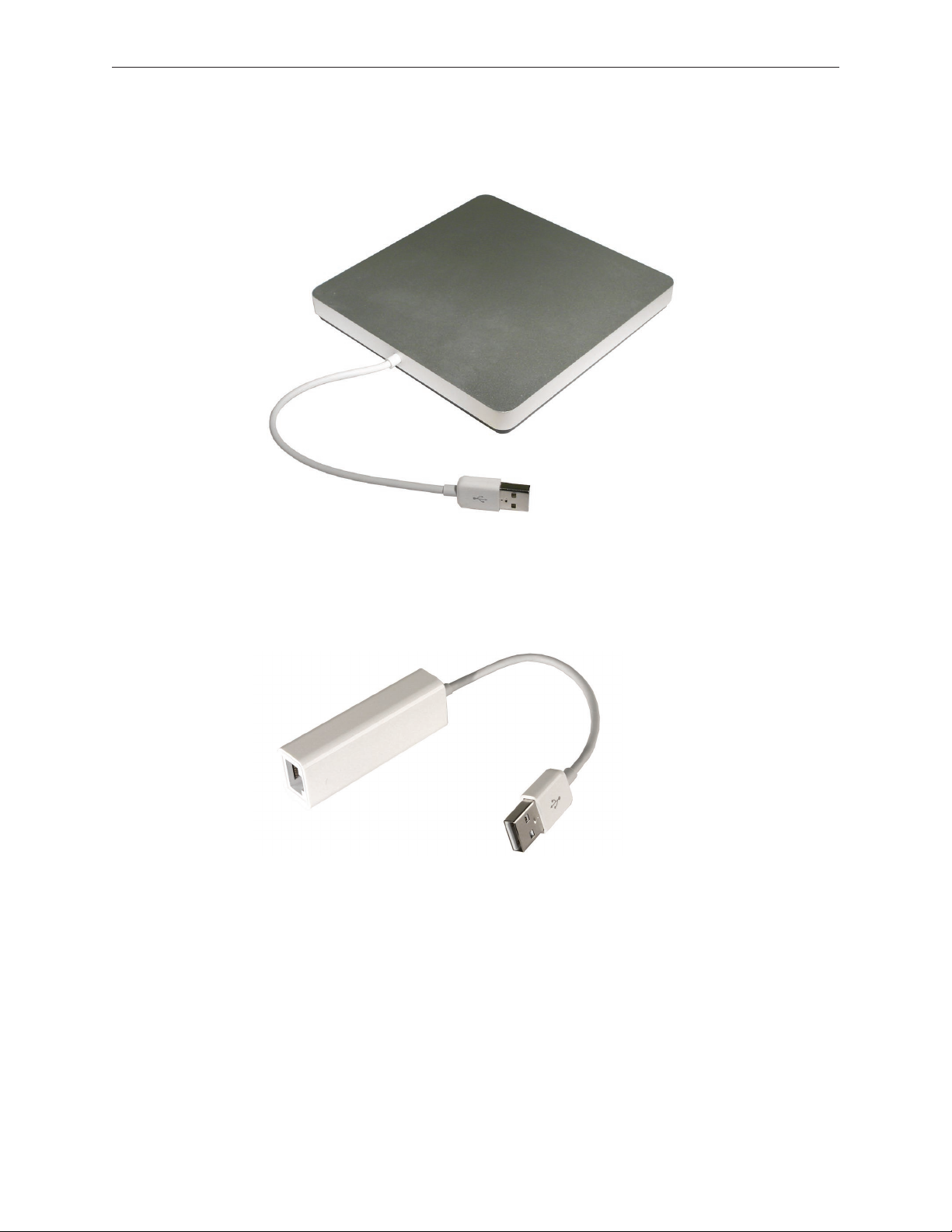
MacBook Air SuperDrive• – An external USB slot-loading SuperDrive, solely bus-powered, works
only with MacBook Air and must be connected directly to a powered USB port on the computer
itself or on an Apple LED Cinema Display. It will not function through any other hub.
USB Ethernet Adapter• – Allows connection to an Ethernet network. The USB Ethernet Adapter
was sold separately for the original and Late 2008 models, but was included with the Mid 2009
model. The adapter looks similar to the Apple USB modem. You can dierentiate between them
by inspecting the ports: the USB Ethernet Adapter uses an RJ-45 connector with eight contacts,
and the USB Modem uses an RJ-11 connector with two contacts.
MagSafe Airline Adapter• – Allows connection to an airline seat power port of any portable
computer with a MagSafe power port.
MacBook Air Basics — General Information 11
Page 12
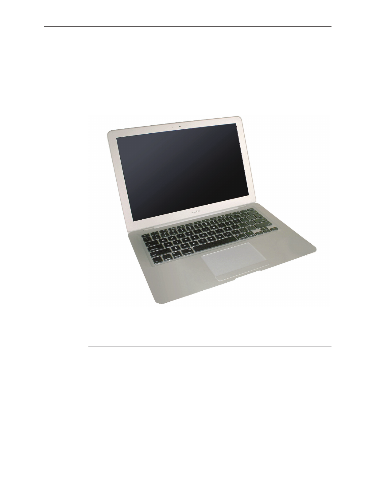
Quick Tour
Following is a quick tour of major features and important repair steps when servicing a MacBook
Air. Please see the specic repair sections to obtain full details on servicing that part.
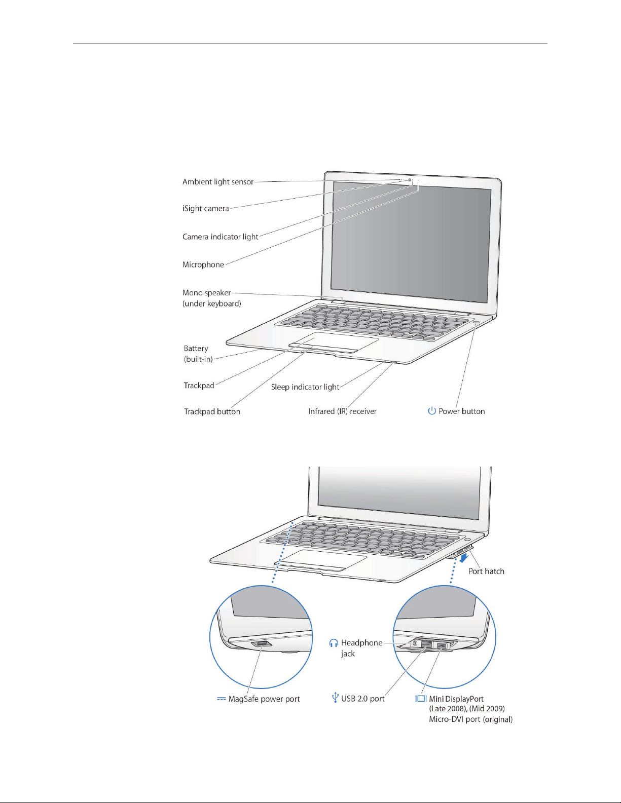
Basic features
Ports
MacBook Air Basics — General Information 12
Page 13
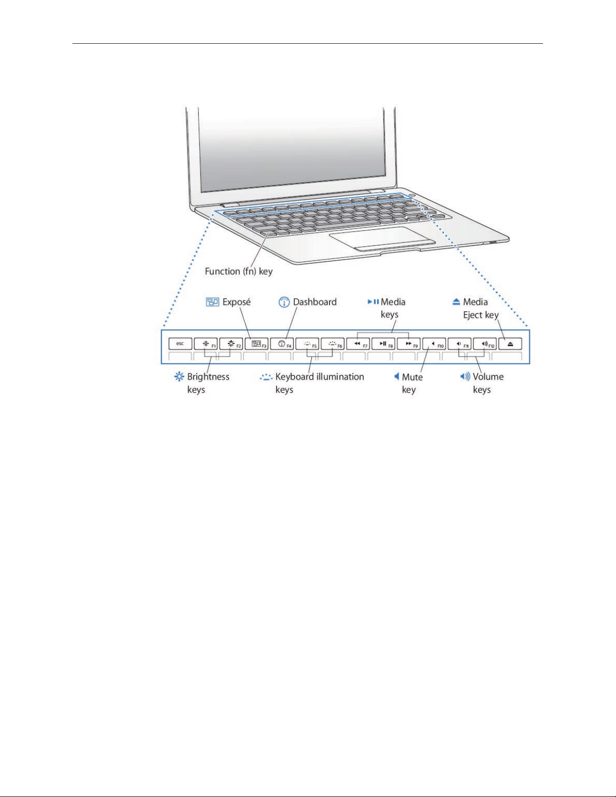
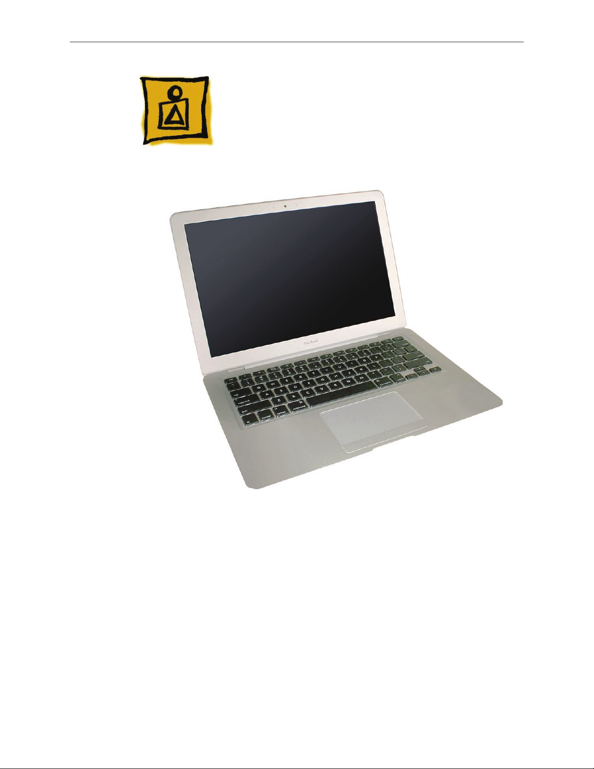
Keyboard features
MacBook Air Basics — General Information 13
Page 14
New Parts and Procedures
Accessing the components
Remove the bottom case to access the components.
Note: Before resting the unit on the workbench, make sure the work area is clear of all debris and
contaminants to avoid damaging the display housing.
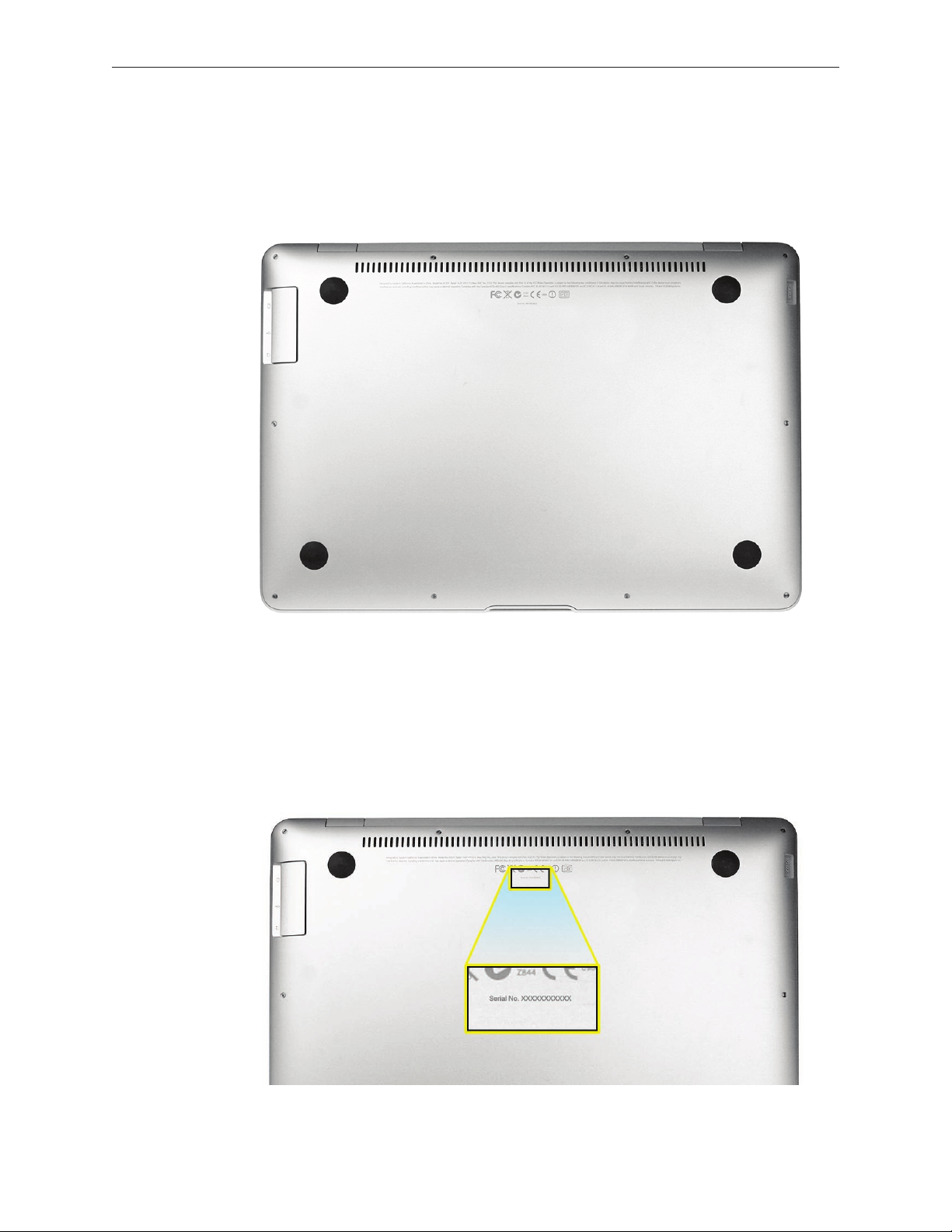
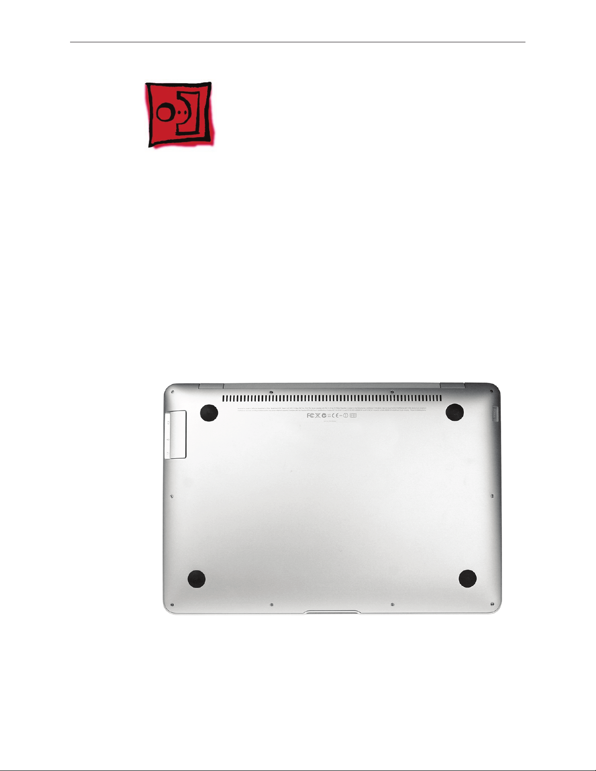
Serial number
The system serial number is etched into the bottom case (shown below). It is centered just below
the regulatory markings. See the bottom case section for information on serial number transfer.
MacBook Air Basics — General Information 14
Page 15

Bottom case angles and curves
Warning: The bottom case screws are inserted at an angle. When reinstalling these screws make
sure you have inserted them at that appropriate angle. Before turning the screw into the boss,
make sure the threads are properly aligned. Use the screwdriver to seat the screw at the correct
angle, and then turn the screw backward (counterclockwise) until you feel the threads “click” into
place. Otherwise, you can damage the screw boss which is part of the top case.
The front edge of the bottom case has ve fragile metal clips that t into ve overhanging tabs
on the top case. Be sure to remove and reinstall the bottom case at a 30º angle.
MacBook Air Basics — General Information 15
Page 16
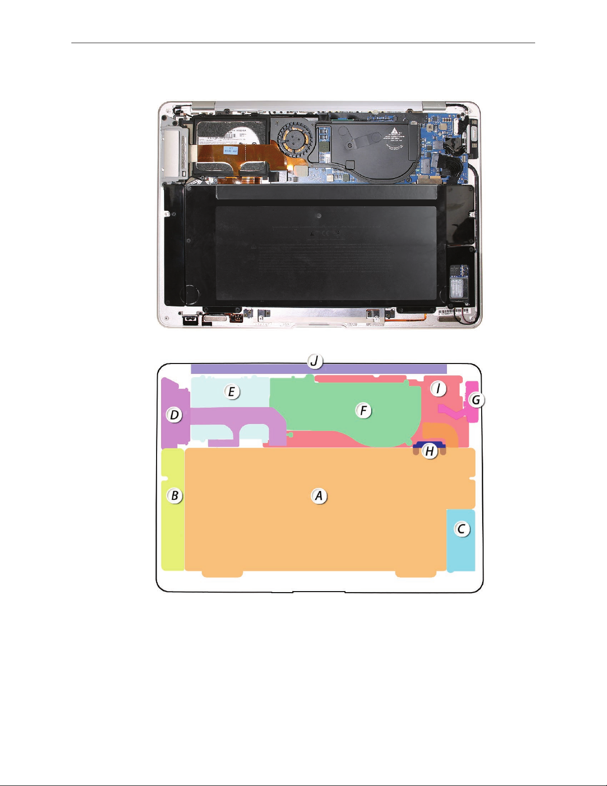
A map of the major modules in the MacBook Air (MacBook Air (original) shown)
A – Battery
B – Speaker D – Port hatch F – Thermal module H – Flex bracket J – Display (hinge)
C – AirPort/
Bluetooth card
E –Hard drive G – MagSafe port I – Logic board
MacBook Air Basics — General Information 16
Page 17
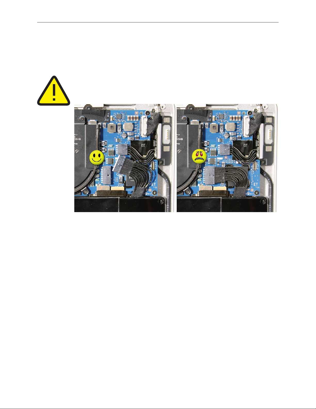
The MacBook Air contains an internal-only battery that is not accessible from the exterior and is
serviceable by authorized Apple service providers only.
Unlike previous systems, when you remove the bottom case, power is still available to the
logic board. Before any further work, disconnect the battery from the logic board connector.
WARNING: Because the battery is internal and connected to the logic board via cable, it MUST BE
DISCONNECTED before performing service procedures. If you fail to do so, live current from the
battery will short circuit the components and render the logic board and/or LVDS cable unusable.
Cables and Connectors
Many cables and cable connectors are very delicate and require specic removal procedures.
Also, new, environmentally friendly Halogen-free materials tend to be stier and less pliable, and
thus require careful handling to avoid damage.
Sleep Sensor
The sleep sensor is located to the left of the sleep indicator light. Like the MacBook Pro, the
magnet is in the display assembly, but since this system is so thin, it is possible to trigger the
sleep sensor with external magnets. For example, when you stack a MacBook Air one on another,
the sleep magnet in the bottom system’s display assembly will trigger the sleep sensor on top.
Battery Icon
A new battery icon, with a triangle and exclamation point inside it means the battery is not
performing to specications (low capacity). It informs the user to have the battery replaced.
Display Repair
Display replacement is with a whole clamshell service part only.
MacBook Air Basics — General Information 17
Page 18
General Module Notes
Module name Notes
Combo AirPort/Bluetooth card Both functions are on a single card.
Hard drive/SSD This part comes with shock mounts pre-applied, including foam pad and
rubber ring (snubber) and ex cable. Do not remove any of these parts.
Battery, lithium ion Not a user-installable part. Handle with care as the enclosure is not
designed to withstand being dropped.
Power adapter, 45W The connector is compatible with other Intel-based MacBook and
MacBook Pro units. However, with only a 45W rating, it has limited
capability to charge or even start up MacBook and MacBook Pro models.
Logic board Logic boards have soldered-on RAM.
Display clamshell The clamshell contains the display, built-in camera, ambient light sensor
and microphone. The LVDS cable carries data signals for the display
video, camera, and ambient light sensor.
MacBook Air SuperDrive,
external
Top case w/ keyboard The top case houses the keyboard, backlit panel, LED, and (IPD) Input
Thermal module Metal heatsink. The fan is attached on the MacBook Air (original).
Speaker assembly Speaker assembly contains a mono speaker. The audio board and audio
MagSafe port assembly This MagSafe connector is compatible with all the other MagSafe
Port hatch assembly The port hatch assembly includes the hatch, ports, and ex cable. The
Audio board
The external MacBook Air SuperDrive only works with the MacBook Air.
Other systems can see the drive itself but cannot load the media.
Devices board. The IPD board provides control logic for the trackpad on
the top, which is calibrated to the top case. The values are stored on the
IPD board. Thus, the two are a matched set. Do not disconnect any ex
cables from the IPD board other than the main IPD cable to the logic
board. All other ex cables connect to parts that are not replaceable.
cable are replaceable separately.
adapters. However, the overmolding on those adapters causes the
system to sit unevenly, resulting in stress to the DC connector cable.
ex cable connects to the audio board to provide analog audio out.
Important: The MacBook Air (Late 2008) and MacBook Air (Mid 2009)
use the same audio board, but it is NOT compatible with the audio
board in the MacBook Air (original). A mismatched board results in no
audio out. The board is located in the speaker assembly.
Support Tools
MacBook Air has an optional external USB SuperDrive that can be purchased separately. This
option allows you to use the Mac OS X Install Disc 1 tools such as Disk Utility and password reset.
You can also reinstall system software.
However, MacBook Air Mac OS X Install Disc 1 also comes with software drivers to share an
optical disk drive on another machine. This remote machine can be a Macintosh running Mac OS
X v10.4.10 or later, or a PC running Windows XP or Windows Vista.
With Remote Disc installed, you can share content of DVDs or CDs, or restore system software
and applications over AirPort or through an Ethernet connection (facilitated by a separate USB
Ethernet adapter). In both cases, the two computers must be on the same subnet.
MacBook Air Basics — General Information 18
Page 19
Migrate data (Mac only)
via AirPort Remote Mac OS X software
via USB Ethernet Remote Mac OS X software
via USB Hard Drive Time Machine software
Install application software, use disk-based tools (Disk Utility, Reset Password)
via MacBook Air SuperDrive Use Mac OS X Disc 1 or application Disc
via AirPort through remote Mac/Windows system Use Mac OS X Disc 1 or application Disc
with Mac OS X Remote Disk software
via Ethernet (with USB adapter) through
remote Mac/Windows system
Re-install system software
via MacBook Air SuperDrive Use Mac OS X Disk 1
via AirPort through remote Mac/Windows system Use Mac OS X Disc 1 with Mac OS X
via Ethernet (with USB adapter) through
remote Mac/Windows system
Use Mac OS X Disc 1 or application Disc
with Mac OS X Remote Disk software
Remote Install software
Use Mac OS X Disc 1 with Mac OS X
Remote Install software
Tools
Servicing the MacBook Air requires the following tools:
Clean, non-marring work surface•
ESD wrist strap and mat•
Multi-compartment screw tray (such as a plastic ice cube tray)•
#000 Phillips screwdriver (magnetized)•
#00 Phillips screwdriver (magnetized)•
Torx T6 screwdriver (magnetized)•
Black stick (nylon probe 922-5065) or other non-conductive nylon or plastic at-blade tool•
Display Repair Fixture (922-8538)•
Cosmetic cover kit (076-1284)•
Gasket kit (076-1285)•
Suction cup (922-8252)•
Thermal paste (922-7144)•
Alcohol pads•
Kapton tape (922-1731) •
Fine-point felt-tip permanent marker•
Standard #2 graphite pencil•
Ruler or straight edge•
Needle-point metal probe•
Needlenose pliers•
Tweezers•
Apple keyboard and mouse (for troubleshooting)•
MacBook Air Basics — General Information 19
Page 20

Electrostatic Discharge (ESD)
Use a properly grounded ESD wrist strap and mat when working on the inside of the computer.
Service Manual Component Photos
In this manual, graphics or photos are intended to help illustrate procedures or information only.
Some photos may show dierent levels of disassembly, board colors, congurations, or computer
congurations than the computer you are working on.
Kapton® Tape Note
New Halogen-free Kapton tape is used to secure cables and connectors where necessary.
During disassembly, note any Kapton tape use and locations—reapply in the same manner. Do
not over apply or build up tape on top of old tape; space tolerances are tight and build up or
extraneous use of tape may cause pressure on other components.
Cable Routing Note
With the MacBook Air’s thin enclosure height, the placement of parts and wiring is more critical
than ever before. During disassembly, note the cable routing. Reassemble in the same manner.
Verify that cables do not route over components when they should route into lower positions or
channels. Verify that the cables are not strained or applying pressure to other components.
Screw Measurement Note
All screw measurements given are the specied full length. Actual measured lengths may vary.
MacBook Air Basics — General Information 20
Page 21
Service Source
Take Apart
MacBook Air
© 2009 Apple Inc. All rights reserved.
Page 22
Bottom Case
Tools
This procedure requires the following tools:
ESD wrist strap and mat•
#00 and #000 Phillips screwdrivers (magnetized)•
Black stick (nylon probe 922-5065) or other non-conductive nylon or plastic at-blade tool•
Preliminary Steps
This procedure requires placing the unit upside down on its display housing. Always use a clean,
debris-free static mat to avoid scratches and other cosmetic damage to the unit.
Part Overview
MacBook Air Take Apart — Bottom Case 22
Page 23
Removal Procedure
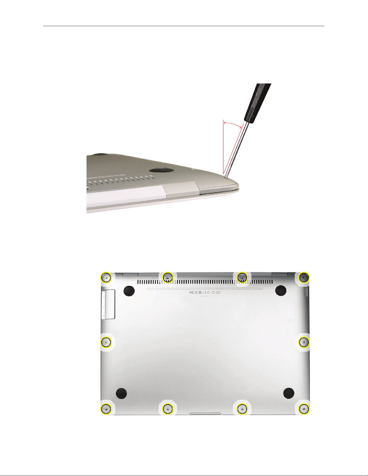
Caution: Each screw boss leading from the top case to the bottom case is angled at a dierent
pitch; thus, the angle at which you drive or loosen the screws must correspond accordingly.
Remove ten Phillips #000 screws, starting from the top center and moving outward in a 1.
circular fashion in both directions.
Note: See the screw map in the Views chapter for the exact placement and size of each screw.
MacBook Air Take Apart — Bottom Case 23
Page 24
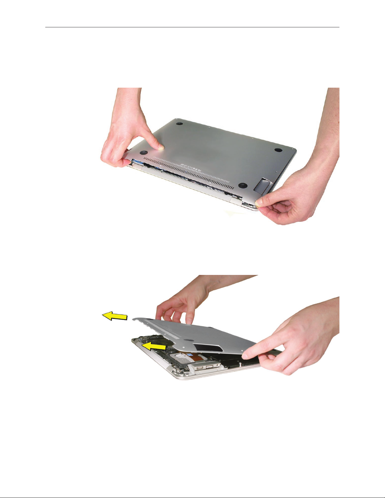
Use your ngernails to grip the edge of the bottom case in the rear corners near the display 2.
hinge, or use a black stick as a wedge to gently pry up the bottom case a few millimeters—
enough to grab the edges with your ngers. You may need to pull with slightly more force
on the right side to lift the corner near the MagSafe adapter port.
Pivot the rear edge upward a few inches to a 303.
º
angle. At that same angle, pull the bottom
case outward from the front edge of the top case to preserve the integrity of the front clips.
MacBook Air Take Apart — Bottom Case 24
Page 25
Serial Number Transfer Instructions
Important Notes:
When replacing the bottom case of a MacBook Air, retain the customer’s original bottom •
case until the repair is complete.
Before installing the replacement bottom case, transfer the serial number from the original •
bottom case to the replacement.
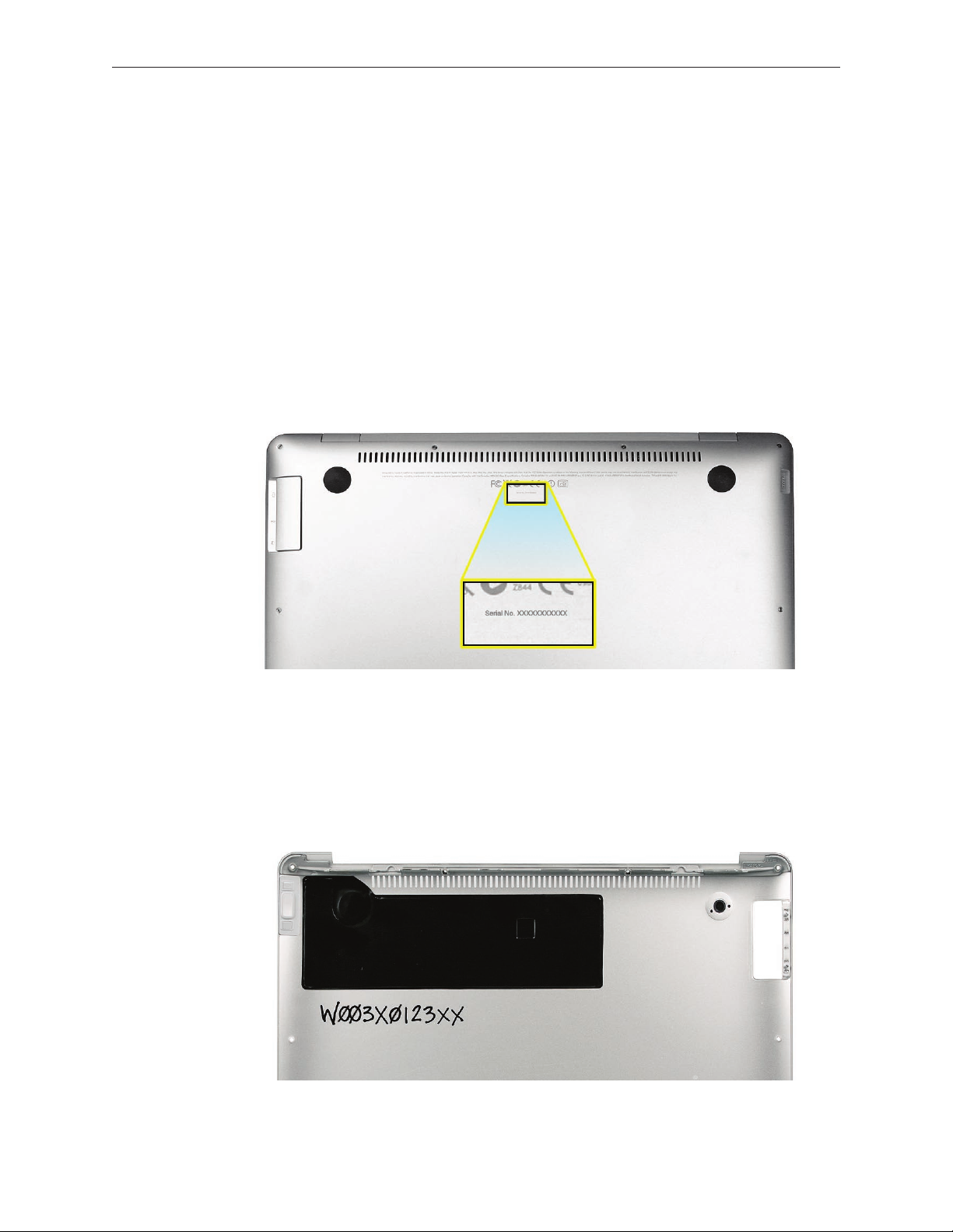
Locate the serial number on the top center of the bottom case (near the vent holes), etched 1.
below the regulatory markings as below. You may need a magnifying glass to read the
characters.
Note: In a bootable system, you can also nd the serial number in “About this Mac” or Apple
System Proler. If the bottom case of the customer’s unit has been previously replaced, see
the subsequent steps for the intended nal written location.
CAUTION: Take great care in deciphering the small typeface of the etched serial number on the
bottom case. It is imperative that you transfer the correct alphanumeric characters. Keep in mind
that Apple serial numbers always use the numbers 1 and 0 instead of the Roman letters “I” and “O.”
On the 2. inside surface of the replacement bottom case, use a ne tip permanent marker to
write the original serial number clearly and legibly in uppercase box letters in the location
below. Look in this location for the serial number on a previously replaced bottom case.
MacBook Air Take Apart — Bottom Case 25
Page 26
Reassembly Procedure
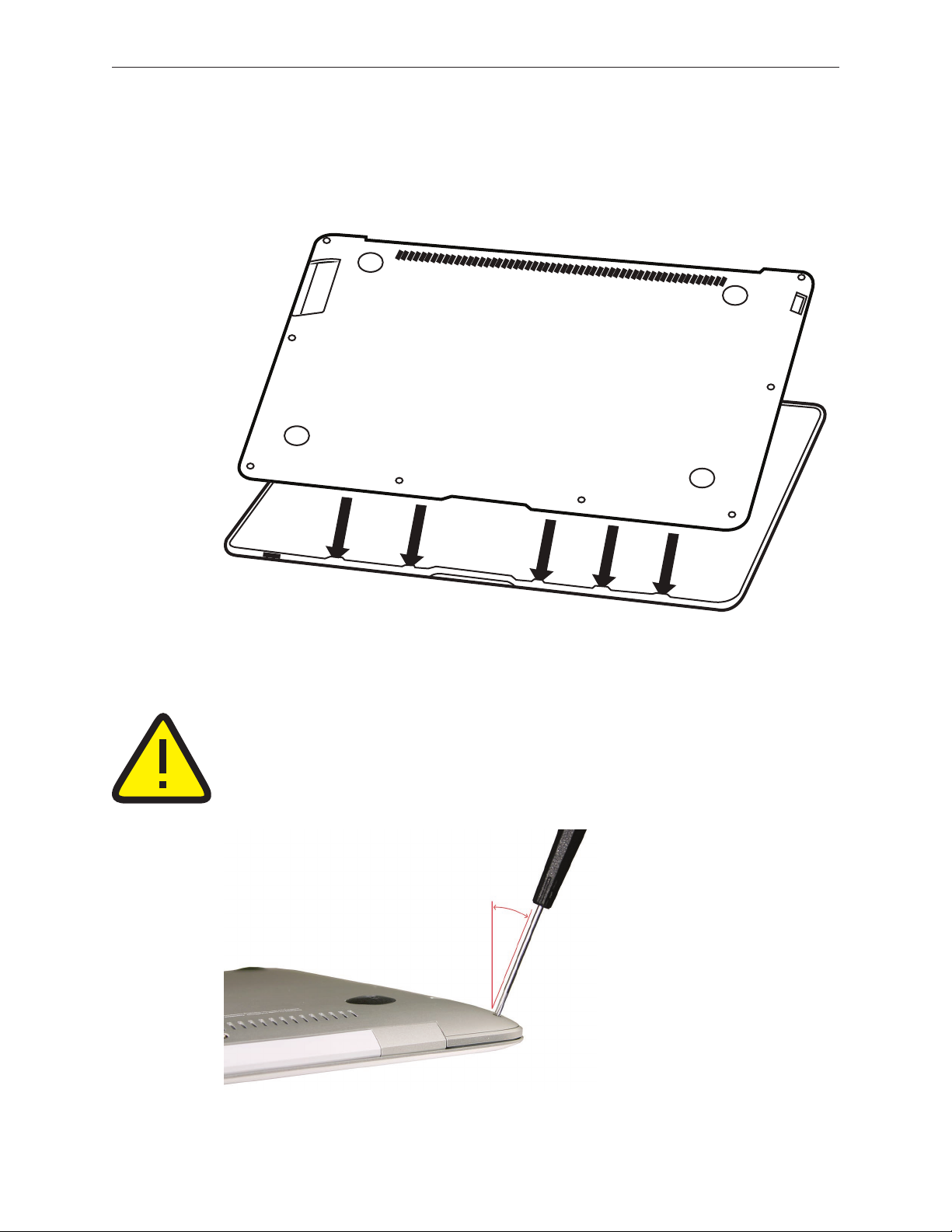
While holding the bottom case at a 301.
tabs on the top case before lowering into place. Make sure no cables are pinched (e.g., the
AirPort/Bluetooth antenna assembly on the right side and the microphone cable in the rear).
º
angle, insert the clips on its front edge into the
Caution: Each screw boss leading from the top case to the bottom case is angled at a dierent
pitch; thus, the angle at which you drive or loosen the screws must correspond accordingly.
Before actually turning the screw into the boss, make sure the threads are properly aligned.
Use the screwdriver to seat the screw at the correct angle, and then turn the screw backward
(counterclockwise) until you feel the threads ‘click’ into place. You may need to do this a few
times to get the exact thread placement. If you feel resistance, back the screw out and start
again. Failure to do so can strip the boss and render the entire top case unusable.
MacBook Air Take Apart — Bottom Case 26
Page 27

Insert ten #000 Phillips screws in the following order, paying close attention to the angle. If 2.
922-8337 (2)
7.9 mm
922-8330 (2)
5.4 mm
922-8328 (6)
3 mm
a particular screw does not seem to mate easily with its screw boss, set that screw aside and
try another of the same size. It should take little eort to screw it in.
Quick Test
Before restarting the system to verify the repair, check for structural and cosmetic integrity by
performing the following tests:
Hold the unit rmly in both hands and gently rock it back and forth; then carefully turn the •
unit over, listening for any loose components or connectors.
Place the unit on a clean, at surface and check for wobble.•
MacBook Air Take Apart — Bottom Case 27
Page 28
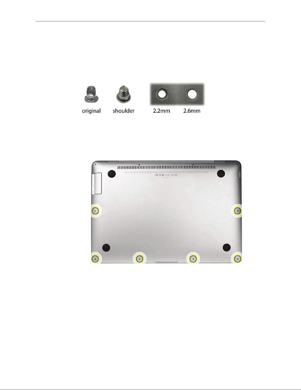
MacBook Air Bottom Case Kit
Note that the kit #076-1317 includes seven new screws (one of which is a spare) along with the
bottom case. Unlike the original bottom case screws, the replacement screws (922-8587) have
a shoulder under the head (see photo below). To accommodate the shoulder, the diameter of
correlating screw holes in the replacement bottom case has increased from 2.2mm to 2.6mm.
Procedure
During removal of an original bottom case, discard the six existing 3mm screws shown 1.
below. These will be replaced by the shoulder screws included in the kit.
When reinstalling the new shoulder screws, make sure the head of the screw sits ush with 2.
the bottom case after installation.
Quick Test
Check for consistently even spacing around the perimeter where the bottom case meets the •
top case.
Check that the unit sits evenly when it is placed on a at surface. You may need to loosen •
and tighten the shoulder screws to properly align the bottom case.
If despite the above adjustments the unit continues to sit unevenly, adjust the enclosure •
alignment by placing the unit on a at surface with the display open to 90º. Apply rm, even
pressure on the right and left sides of the palm rests to level the footing of the machine.
MacBook Air Take Apart — Bottom Case 28
Page 29
Battery
Tools
This procedure requires the following tools:
ESD wrist strap and mat•
#00 and #000 Phillips screwdrivers (magnetized)•
Black stick (nylon probe 922-5065) or other non-conductive nylon or plastic at-blade tool•
Preliminary Steps
This procedure requires placing the unit upside down on its display housing. Always use a clean,
debris-free static mat to avoid scratches and other cosmetic damage to the unit.
Before you begin, remove the bottom case.
CAUTION: The battery must be disconnected from the logic board before proceeding further.
Failure to do so is likely to result in irreparable damage to expensive components such as the
logic board and/or LVDS cable.
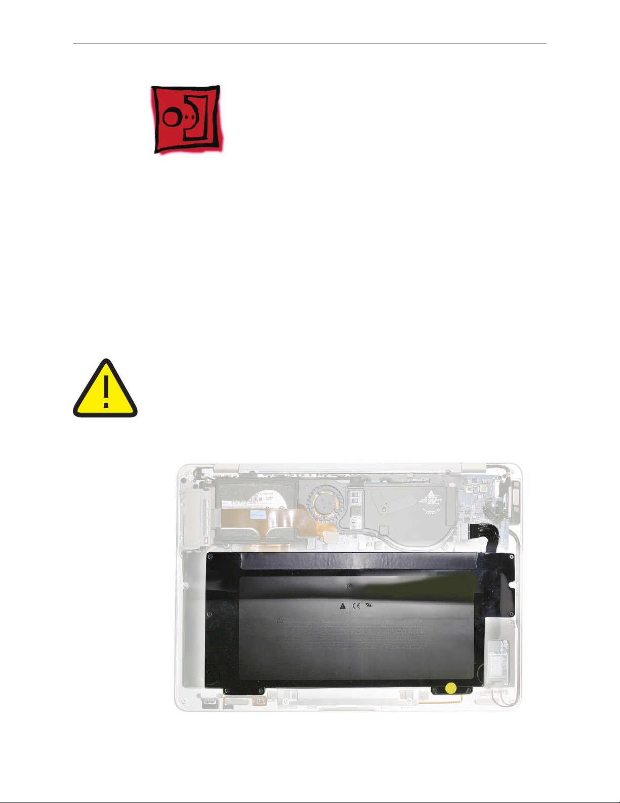
Part Location
MacBook Air Take Apart — Battery 29
Page 30
Removal Procedure
Disconnect the battery cable connector from the logic board, taking care to keep the cable 1.
connector at when pulling it out of its mate. Use your thumb on top and a black stick
beneath to prevent too much bend in the cable. An alternative is to use your index ngers
(and nails) to grab the sides of the connector and pull straight out, level with the board.
Note: Halogen-free cables and connectors are delicate. Handle with care to avoid damage.
MacBook Air Take Apart — Battery 30
Page 31

Remove nine #00/000 Phillips screws in the following order.2.
Note: You may nd screws tightly wedged in their sockets. If so, avoid stripping the head by
bearing down rmly (albeit carefully) to release the screw and its locktight adhesive.
Lift the battery out evenly with both hands on either side to avoid bending or straining the 3.
battery pack. Always handle by the edges to avoid pressure to its inner surfaces. To keep the
battery cable intact, do not lift or hold the battery using the cable or connector.
MacBook Air Take Apart — Battery 31
Page 32

Reassembly Procedure
3.1 mm
3.9 mm
6.9 mm
3.1 mm
3.9 mm
3.9 mm
3.9 mm
Align the screw hole in the upper left with its corresponding boss on the top case, and set 1.
the battery gently in place.
Install the nine #00/000 Phillips screws in the following order.2.
Note: This screw order is dierent from the removal order in the previous section.
CAUTION: Delicate screw pressure and precise torque must be applied to avoid cracking the
battery case. Turn the screws until just hand-tight, then back out 1/4 turn.
MacBook Air Take Apart — Battery 32
Page 33

Quick Test
Verify your repair by successfully starting up the system on battery power only.
MacBook Air Take Apart — Battery 33
Page 34

AirPort/Bluetooth Card
Tools
This procedure requires the following tools:
ESD wrist strap and mat•
#00 and #000 Phillips screwdrivers (magnetized)•
Black stick (nylon probe 922-5065) or other non-conductive nylon or plastic at-blade tool•
Preliminary Steps
This procedure requires placing the unit upside down on its display housing. Always use a clean,
debris-free static mat to avoid scratches and other cosmetic damage to the unit.
Before you begin, remove the following:
Bottom case•
Battery•
CAUTION: The battery must be disconnected from the logic board before proceeding further.
Failure to do so is likely to result in irreparable damage to expensive components such as the
logic board and/or LVDS cable.
Part Location
MacBook Air Take Apart — AirPort/Bluetooth Card 34
Page 35

Removal Procedure
Remove the two #000 Phillips screws at the upper right (3.9 mm) and lower left corner 1.
(4.7 mm) of the black plastic AirPort/Bluetooth card cover.
Lift o the card cover.2.
Disconnect the ex cable from the AirPort/Bluetooth card. 3.
Disconnect one Bluetooth antenna connector on the top right of the card, and two AirPort 4.
antenna connectors on the lower part of the card.
Remove the small black 3.2 mm screw in the upper right corner.5.
Remove the AirPort/Bluetooth card carefully, holding the board by the edges only.6.
Store the AirPort/Bluetooth card in an anti-static, shielded bag.7.
MacBook Air Take Apart — AirPort/Bluetooth Card 35
Page 36

Reassembly Procedure
When reinstalling the AirPort/Bluetooth card, use the pin (shown below) on the top case to 1.
align the bottom right corner of the board.
Install the small black Phillips 3.2mm screw in the upper right corner (see below). 2.
Connect the Bluetooth antenna connector at the top right (see below). 3.
Note: Be sure to route the antenna connector and cable beside the screw for a secure t.
Connect the two AirPort antenna connectors at the lower edge of the card. Cable lengths 4.
correspond to placement. Connect the orange ex cable.
MacBook Air Take Apart — AirPort/Bluetooth Card 36
Page 37

Replace the AirPort/Bluetooth card cover.5.
Install the two #000 Phillips screws at the upper right (3.9 mm) and lower left corner 6.
(4.7 mm) of the card cover.
Quick Test
In Apple System Proler, verify AirPort and Bluetooth presence as well as settings.1.
Check AirPort antenna functionality by browsing to a known-good web site.2.
Check Bluetooth antenna functionality by attempting to transfer a le to another Mac.3.
MacBook Air Take Apart — AirPort/Bluetooth Card 37
Page 38

Speaker Assembly
Tools
This procedure requires the following tools:
ESD wrist strap and mat•
#00 and #000 Phillips screwdrivers (magnetized)•
Black stick (nylon probe 922-5065) or other non-conductive nylon or plastic at-blade tool•
Preliminary Steps
This procedure requires placing the unit upside down on its display housing. Always use a clean,
debris-free static mat to avoid scratches and other cosmetic damage to the unit.
Before you begin, remove the following:
Bottom case•
Battery•
CAUTION: The battery must be disconnected from the logic board before proceeding further.
Failure to do so is likely to result in irreparable damage to expensive components such as the
logic board and/or LVDS cable.
Part Location
MacBook Air Take Apart — Speaker Assembly 38
Page 39

Removal Procedure
Remove the two Phillips #000 screws securing the speaker assembly cover to the top case. 1.
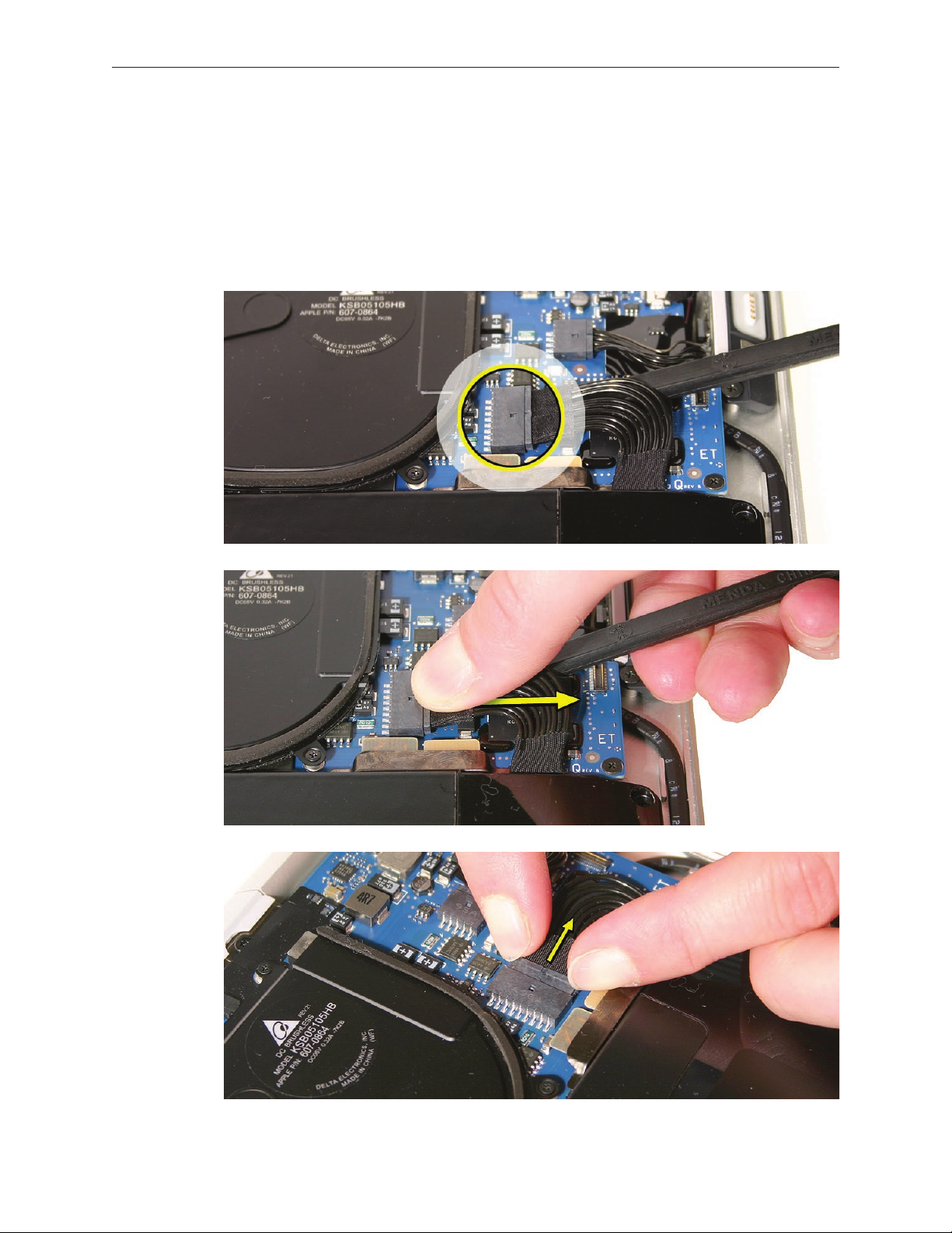
Carefully lift the speaker assembly and disconnect the audio cable connector (shown below).2.
MacBook Air Take Apart — Speaker Assembly 39
Page 40

Slide a black stick between the audio jack cable leading from the port hatch assembly and 3.
the speaker board ex cable connected to the top case, gently loosening the adhesive
between the two cables little by little.
Note: While separating the upper cable from the lower one, hold the lower one down as you
move the black stick to keep the speaker ex cable adhered to the top case.
Carefully pry up the small cable connector board from its tab on the hard drive frame. Note 4.
the small plastic peg at the corner of the tab which mates with a corresponding hole on the
connector board. Try to keep the adhesive bonded to the hard drive frame if possible.
MacBook Air Take Apart — Speaker Assembly 40
Page 41

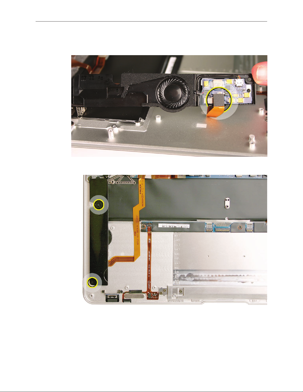
Carefully disconnect the audio-out cable connector (shown below).5.
Note: The audio board and the audio-out cable are separately replaceable. The board can be
lifted out and is secured to a pin and with adhesive. The speaker wire connector lifts straight
up when disconnecting, the audio-out cable slides out sideways. When installing the audio out
cable, connect it to the audio board, install the audio board, then route the cable in the channel
before connecting the speaker cable to the board, so that it runs underneath the speaker cable.
Verify that the EMI gasket (shown) is in place; transfer if needed.
MacBook Air Take Apart — Speaker Assembly 41
Page 42

Reassembly Procedure
Connect the audio-out cable connector.1.
Gently place the cable connector board on the hard drive frame tab, using the peg at the 2.
front of the tab as a guide for placement. Make sure the board is rmly adhered to the tab
and the black cable leading from the connector is routed close to the top case.
MacBook Air Take Apart — Speaker Assembly 42
Page 43
Connect the audio cable connector to the speaker board. Place the speaker assembly in the 1.
correct orientation on the top case.
Install the two Phillips #000 screws on the speaker assembly cover. 2.
Quick Test
Play a QuickTime video to check speaker output as well as the audio-out jack on the port hatch.
MacBook Air Take Apart — Speaker Assembly 43
Page 44

Port Hatch Assembly
Tools
This procedure requires the following tools:
ESD wrist strap and mat•
#00 and #000 Phillips screwdrivers (magnetized)•
Black stick (nylon probe 922-5065) or other non-conductive nylon or plastic at-blade tool•
Preliminary Steps
This procedure requires placing the unit upside down on its display housing. Always use a clean,
debris-free static mat to avoid scratches and other cosmetic damage to the unit.
Before you begin, remove the following:
Bottom case•
Battery•
Speaker assembly•
CAUTION: The battery must be disconnected from the logic board before proceeding further.
Failure to do so is likely to result in irreparable damage to expensive components such as the
logic board and/or LVDS cable.
Part Location
MacBook Air Take Apart — Port Hatch Assembly 44
Page 45

Removal Procedure
Remove four #00 Phillips shoulder screws on the port hatch. 1.
Note the location of the port hatch ex cable connector to the logic board.2.
MacBook Air Take Apart — Port Hatch Assembly 45
Page 46

Lift the port hatch ex connector using the small tab on the right side to lift this connector 3.
straight up (not rocked back-and-forth or side-to-side), keeping the connector parallel to its
mate to avoid damage to the connector pins.
Replacement Notes
Note: Make sure the port hatch ex connector is horizontally straight and ush on the same
plane as the logic board. Firmly press down the entire connector to reinstall.
Note: Do not overtighten the screws that secure the port hatch assembly. Keep in mind that
these shoulder screws are designed to provide room for the component to have a bit of play in
its position on the top case. A small amount of lateral movement after assembly is expected.
Quick Test
Check all the I/O ports (especially audio-out) to verify port hatch ex and audio jack connections.
MacBook Air Take Apart — Port Hatch Assembly 46
Page 47

MagSafe Assembly
Tools
This procedure requires the following tools:
ESD wrist strap and mat•
#00 and #000 Phillips screwdrivers (magnetized)•
Black stick (nylon probe 922-5065) or other non-conductive nylon or plastic at-blade tool•
Preliminary Steps
This procedure requires placing the unit upside down on its display housing. Always use a clean,
debris-free static mat to avoid scratches and other cosmetic damage to the unit.
Before you begin, remove the following:
Bottom case•
Battery•
CAUTION: The battery must be disconnected from the logic board before proceeding further.
Failure to do so is likely to result in irreparable damage to expensive components such as the
logic board and/or LVDS cable.
Part Location
MacBook Air Take Apart — MagSafe Assembly 47
Page 48

Removal Procedure
CAUTION: The battery must be disconnected from the logic board before proceeding further.
Failure to do so is likely to result in irreparable damage to expensive components such as the
logic board and/or LVDS cable.
Remove the Phillips #000 screw that secures the LVDS cable ground clip.1.
With your ngers or a black stick, disconnect the LVDS cable using the tabs on either side of 2.
the connector. Be sure to keep the connector level (horizontally parallel to the logic board).
MacBook Air Take Apart — MagSafe Assembly 48
Page 49

Remove the two Phillips shoulder screws that hold down the MagSafe assembly. 3.
Disconnect the MagSafe cable by sliding a black stick under the cabling right next to the 4.
connector and sandwiching the connector between the black stick and your thumb. Be sure
to keep the connector at (i.e., horizontally parallel to the logic board). Be careful that the
individual cables don’t get bent, damaged or misaligned.
Reassembly Tips
The magnets on the MagSafe assembly are strong and can quickly attract metal screws. •
When reinstalling the MagSafe assembly, use your ngers or perhaps tweezers to hold the
screws in place while turning the screwdriver.
Do not overtighten the screws that secure the MagSafe assembly. Keep in mind that these •
shoulder screws are designed to provide room for the component to have a bit of play in its
position on the top case. A small amount of lateral movement after assembly is expected.
Quick Test
Attach a MagSafe adapter DC plug to the MagSafe port to see if the LED turns amber or green,
depending on the level of battery charge in the unit.
MacBook Air Take Apart — MagSafe Assembly 49
Page 50

Hard Drive/SSD
Tools
This procedure requires the following tools:
ESD wrist strap and mat•
#00 and #000 Phillips screwdrivers (magnetized)•
Black stick (nylon probe 922-5065) or other non-conductive nylon or plastic at-blade tool•
Preliminary Steps
This procedure requires placing the unit upside down on its display housing. Always use a clean,
debris-free static mat to avoid scratches and other cosmetic damage to the unit.
Before you begin, remove the following:
Bottom case•
Battery•
CAUTION: The battery must be disconnected from the logic board before proceeding further.
Failure to do so is likely to result in irreparable damage to expensive components such as the
logic board and/or LVDS cable.
Part Location
MacBook Air Take Apart — Hard Drive/SSD 50
Page 51

Important Notes:
MacBook Air (Late 2008 & Mid 2009)
MacBook Air (original)
Use only the ex cable that comes in the box with the service replacement drive. •
Do NOT transfer or use an existing ex cable.
This ex cable must be installed and the included mylar cover applied over the connector. •
The connectors on the drives are extremely fragile and have a limited insertion life. Use •
extreme care when opening and closing the connectors.
The MacBook Air (Late 2008) and MacBook Air (Mid 2009) use the same type of connectors •
and ex cables, which is dierent from the ones used by the MacBook Air (original). The
drives and cables are not interchangeable between the original model and later models.
The MacBook Air (Late 2008) and MacBook Air (Mid 2009) drive connector opens backwards, •
and the MacBook Air (original) drive connector opens forward.
Install the included mylar over the cable and connector, once secured.•
Transfer the hard drive bracket to the replacement drive.•
If the hard drive ex cable should become dislodged or removed during repair, you •
must replace the ex cable.
MacBook Air Take Apart — Hard Drive/SSD 51
Page 52

Removal Procedure
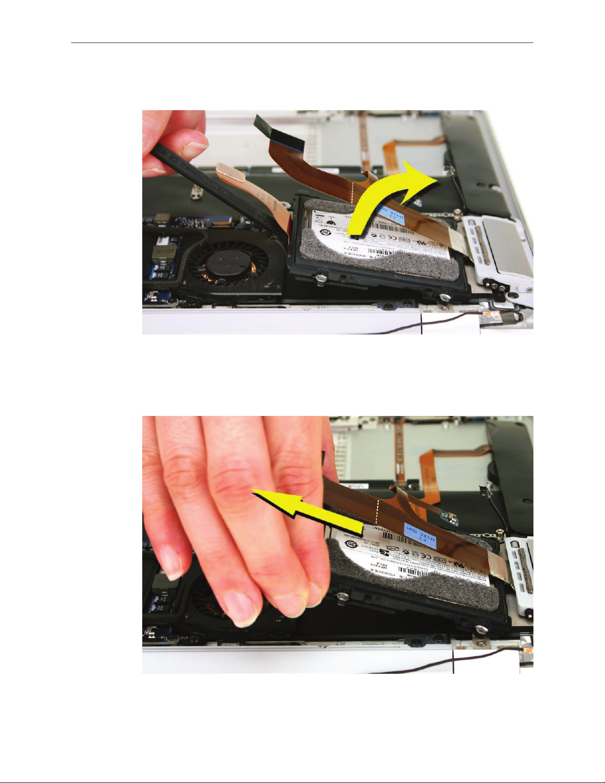
Identify the intersecting cables below: (1) the port hatch audio ex extension (branching o 1.
from the port hatch ex cable) which connects to (2) the audio-out cable coming from the
speaker assembly on the left.
The port hatch audio ex extension is adhered to another ex cable on the top case (the 2.
audio ex cable between the audio board and logic board). Use the at end of a black stick
to carefully separate the top ex cable from its adhesion to the ex cable underneath.
Pry up the small blue board at the end of the port hatch ex cable extension away from the 3.
hard drive frame, using care to preserve the adhesive for reuse.
MacBook Air Take Apart — Hard Drive/SSD 52
Page 53

Lift the cables away from the hard drive frame and disconnect the audio-out cable on the 4.
left from the port hatch ex extension on the right.
Locate the port hatch ex cable connector to the logic board.5.
Lift the port hatch ex connector using the small tab on the right side to lift this connector 6.
straight up (not rocked back-and-forth or side-to-side), keeping the connector as parallel to
its mate as possible to avoid damage to the connector pins.
MacBook Air Take Apart — Hard Drive/SSD 53
Page 54

On the reverse side of the hard drive assembly, examine the routing to the microphone cable 7.
through channels on the hard drive frame and under the thermal module fan.
Note: Notice two black plastic cosmetic pieces designed to prevent screws and cabling from
being visible through vent holes in the bottom case—one molded to t the edge of the fan and
a smaller piece molded to t the hard drive frame. You will remove them in this procedure.
Begin to remove the cosmetic fan cover using a black stick to wedge it out from the left side. 8.
MacBook Air Take Apart — Hard Drive/SSD 54
Page 55

Grab the cosmetic fan cover, pivoting outward. Pull the cover out from under the fan at the 9.
angle shown below. Note the placement of the cover for reinstallation.
With the cosmetic fan cover removed, lift the mylar tab shown below to expose the 10.
microphone cable’s connection to the logic board.
Disconnect the microphone cable connector from the logic board using the pointed end of 11 .
the black stick to push the side tabs on the connector.
MacBook Air Take Apart — Hard Drive/SSD 55
Page 56

Note the cable routing under a clip on the fan and two sets of clips on the hard drive frame.12.
Carefully extract the microphone cable from the routing clips on the hard drive frame. 13 .
Because it is delicate, take great care not to pinch or pull this cable.
Remove the grounding screw that secures the microphone cable to the top case.14.
MacBook Air Take Apart — Hard Drive/SSD 56
Page 57

Remove the cosmetic screw cover on the hard drive frame using a black stick to work it 15 .
outward from the frame. Keep the adhesive on the plastic piece rather than the screw, if
possible. Set aside this small cosmetic screw cover with your hard drive screws.
Remove the four Phillips screws from the hard drive bracket. Disconnect the hard drive ex 16.
cable to the logic board. (Note that unlike the photo below, the port hatch assembly does
not need to be removed in order to remove the hard drive.)
MacBook Air Take Apart — Hard Drive/SSD 57
Page 58
Lift up the hard drive frame an inch or so on the logic board side, pivoting toward the 17.
outside of the top case.
Remove the hard drive assembly at an angle, out from under the port hatch assembly ex 18.
cable, taking care not to bend or strain the cable.
MacBook Air Take Apart — Hard Drive/SSD 58
Page 59

Replacement Notes
Reassembly is an exact reversal of the above procedure. Take care to connect all ex cables fully,
and be sure to seat the audio-out cable connector board over the pin on the hard drive frame.
Quick Test
Start up the computer to verify that it recognizes and starts up from the hard drive.
MacBook Air Take Apart — Hard Drive/SSD 59
Page 60

Thermal Module and Logic Board Combined
Tools
This procedure requires the following tools:
ESD wrist strap and mat•
#00 and #000 Phillips screwdrivers (magnetized)•
Black stick (nylon probe 922-5065) or other non-conductive nylon or plastic at-blade tool•
Preliminary Steps
This procedure requires placing the unit upside down on its display housing. Always use a clean,
debris-free static mat to avoid scratches and other cosmetic damage to the unit.
Before you begin, remove the following:
Bottom case•
Battery•
Hard drive assembly•
CAUTION: The battery must be disconnected from the logic board before proceeding further.
Failure to do so is likely to result in irreparable damage to expensive components such as the
logic board and/or LVDS cable.
Part Location
MacBook Air Take Apart — Thermal Module and Logic Board Combined 60
Page 61

Removal Procedure
Remove two tiny Phillips screws that hold the ex bracket 1. (bottom) right to the top case. Set
aside the ex bracket with the screws.
Disconnect the audio ex cable from the lower left corner of the logic board.2.
Disconnect the IPD and AirPort/Bluetooth ex cables on the lower right side of the board.3.
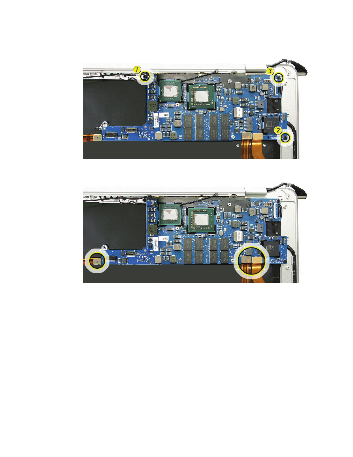
Remove three Phillips screws securing the logic board to the top case and one (upper-left-4.
most) Phillips screw securing the thermal module to the top case.
MacBook Air Take Apart — Thermal Module and Logic Board Combined 61
Page 62

Lift and remove the entire module assembly rmly holding the edges of the logic board. 5.
Note: Take care not to separate the thermal module from the logic board. Otherwise, you
must replace the existing thermal paste to ensure proper reinstallation. See thermal module
chapter for instructions on how to replace the thermal paste.
Reassembly Procedure
When reinstalling the logic board / thermal module assembly, guide the hole in the lower 1.
left corner of the board onto the post in the center of the top case as shown below.
MacBook Air Take Apart — Thermal Module and Logic Board Combined 62
Page 63

Align and seat the board, and reinstall the four screws and three ex connectors below. 2.
With its two tiny Phillips screws, reinstall the ex bracket that secures the IPD and AirPort-3.
Bluetooth ex cable connectors.
Quick Test
Check keyboard response, keyboard backlight, trackpad, IR (use Apple Remote) and sleep •
indicator light to verify correct Input Devices (IPD) ex cable connection.
Attach power adapter and charge battery to check that the MagSafe connector is properly •
connected.
In Apple System Proler, verify AirPort and Bluetooth presence as well as settings.•
Check all I/O ports on port hatch.•
MacBook Air Take Apart — Thermal Module and Logic Board Combined 63
Page 64

Thermal Module and Fan
On the MacBook Air (Late 2008) and MacBook Air (Mid 2009) the fan and thermal module are
separate parts and can be removed separately. On the MacBook Air (original) the fan and thermal
module are one combined part and cannot be separated.
Tools
This procedure requires the following tools:
ESD wrist strap and mat•
#00 and #000 Phillips screwdrivers (magnetized)•
Black stick (nylon probe 922-5065) or other non-conductive nylon or plastic at-blade tool•
Preliminary Steps
This procedure requires placing the unit upside down on its display housing. Always use a clean,
debris-free static mat to avoid scratches and other cosmetic damage to the unit.
Before you begin, remove the following:
Bottom case•
Battery•
Hard drive assembly•
CAUTION: The battery must be disconnected from the logic board before proceeding further.
Failure to do so is likely to result in irreparable damage to expensive components such as the
logic board and/or LVDS cable.
MacBook Air Take Apart — Thermal Module and Fan 64
Page 65

Part Location
Removal Procedure
Follow the procedures under the heading for the product model being worked on.
For MacBook Air (Late 2008) and MacBook Air (Mid 2009):
If replacing the fan... it can be removed without removing the thermal module, which avoids
cleaning and replacing thermal paste on the thermal module and logic board.
Remove the three screws shown.1.
MacBook Air Take Apart — Thermal Module and Fan 65
Page 66

Disconnect the fan cable from its connection to the logic board. Insert the black stick into 2.
the small square recess on the connector to push it out of its mate.
Note: This cable and connector are delicate. Handle with care.
Use a black stick to carefully lift the fan where shown here, being very careful of the 3.
surrounding components.
MacBook Air Take Apart — Thermal Module and Fan 66
Page 67

Lift just enough for the fan to clear the screw boss as you slide it out from under the thermal 4.
module arm.
Use the same method when replacing the fan. Verify that the fan screw hole is captured by
the screw boss, and the fan cable is routed correctly, see below.
If removing or replacing the thermal module... remove the screws shown, then follow the
MacBook Air (original) procedures to remove and replace the thermal module.
MacBook Air Take Apart — Thermal Module and Fan 67
Page 68

For MacBook Air (original)
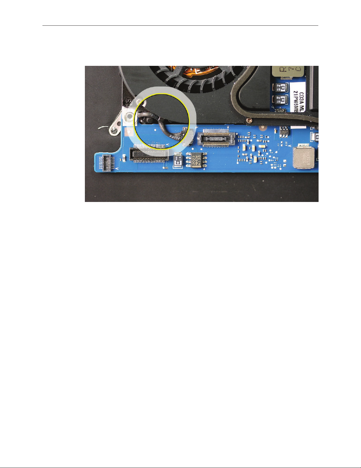
Remove one #00 (upper left) and three #000 (center and right) Phillips screws. The center 1.
screw also removes a boomerang-shaped clamp that secures the thermal module to the
both processors. Set the boomerang clamp aside with the screws.
Note: The fan cable connection to the logic board is circled in orange at the lower left.
Disconnect the fan cable from its connection to the logic board. Insert the black stick into 2.
the small square recess on the connector to push it out of its mate.
Note: This cable and connector are delicate. Handle with care.
MacBook Air Take Apart — Thermal Module and Fan 68
Page 69

Gently lift the thermal module up from the logic board. You should feel a slight resistance 3.
when pulling up as the thermal paste releases. Hold the module rmly by the edges only.
Hold the module by the edges only.4.
Warning: Whenever the thermal module is separated from the logic board (even if you are
reinstalling the same logic board and/or thermal module), the thermal paste must be replaced.
Failure to do so can cause the computer to overheat and incur damage.
MacBook Air Take Apart — Thermal Module and Fan 69
Page 70

Replacing the Thermal Paste
If the thermal module will be reinstalled and/or the existing logic board will remain in place,
the old thermal paste must be removed from both modules, and new thermal paste applied.
Use a black stick to remove as much thermal paste as possible from the logic board chips. 1.
Important: Use extreme care not to damage the chip or logic board components.
Use a black stick to remove thermal paste from the two mating pads on the under side of 2.
the thermal module.
MacBook Air Take Apart — Thermal Module and Fan 70
Page 71

Use an alcohol wipe to completely clean the residual thermal paste from the two chips on 3.
the logic board and the two pads on the heatsink.
Important: Use extreme care not to damage the logic board components.
Note: Apple part no. 922-7144 contains three thermal paste syringes.
MacBook Air Take Apart — Thermal Module and Fan 71
Page 72

Note the contents of the syringe of thermal paste. 4.
Important: One syringe contains enough paste for four chips (two repairs). Use one-quarter
of the syringe contents per chip. Using a felt-tip pen, mark the 1/4 points on the syringe
before applying the rst dab.
Important: Avoid unnecessary contact with new thermal paste, as dirt and body oils reduce
the paste’s conductivity.
Put a 1cc dab (roughly one quarter of a full syringe) of thermal paste in the center of each 5.
chip mating surface, as shown.
MacBook Air Take Apart — Thermal Module and Fan 72
Page 73

Reassembly Procedure
Caution: Before reinstalling the thermal module onto the logic board, you MUST have replaced
the thermal paste already. See above section for instructions.
While centering the thermal module pads over the two chips, lower the thermal module 1.
onto the logic board.
Verify that the thermal module screw clips are aligned with their bosses underneath, then 2.
press gently but rmly over the two chips to make sure the thermal paste adheres evenly.
MacBook Air Take Apart — Thermal Module and Fan 73
Page 74

Set the thermal module boomerang clamp in the center of the thermal module using the 3.
screw hole for initial alignment. Then pivot the boomerang so that the small hole near the
“V” of the clamp lines up with its corresponding hole in the thermal module beneath.
Install one #00 Phillips screw in the upper left corner near the fan, two #000 screws in the 4.
clips on the right upper and lower corners of the thermal module, and then fasten the center
#000 screw on the boomerang clamp last. Do not overtighten the center screw.
MacBook Air Take Apart — Thermal Module and Fan 74
Page 75
Connect the fan cable from the thermal module to the logic board. Pay close attention to 5.
cable routing. See picture below for more detail.
Quick Test
After reassembly, start up the computer and let the system run for a period of time until the fan
comes on; then check for fan noise.
MacBook Air Take Apart — Thermal Module and Fan 75
Page 76

Logic Board
Tools
This procedure requires the following tools:
ESD wrist strap and mat•
#00 and #000 Phillips screwdrivers (magnetized)•
Black stick (nylon probe 922-5065) or other non-conductive nylon or plastic at-blade tool•
Preliminary Steps
This procedure requires placing the unit upside down on its display housing. Always use a clean,
debris-free static mat to avoid scratches and other cosmetic damage to the unit.
Before you begin, remove the following:
Bottom case•
Battery•
Speaker assembly•
Port hatch assembly•
Hard drive assembly•
MagSafe assembly•
CAUTION: The battery must be disconnected from the logic board before proceeding further.
Failure to do so is likely to result in irreparable damage to expensive components such as the
logic board and/or LVDS cable.
Part Location
MacBook Air Take Apart — Logic Board 76
Page 77

Removal Procedure
Remove two tiny Phillips screws that hold the ex bracket 1. (bottom) right to the top case.
Remove three identical Phillips screws in the corners of the logic board and disconnect three 2.
connectors at the bottom edge—the audio cable connector, the Input Devices (IPD) board
ex connector and the AirPort/Bluetooth card ex connector.
MacBook Air Take Apart — Logic Board 77
Page 78

When removing the logic board, grasp the board in the middle lengthwise by the edges 3.
only. Do not hold the board by any narrow areas. Take all ESD precautions when handling it.
Warning: To avoid exing the logic board, hold the board vertically along the wide sides. Do
not hold the board by the ends or by the narrow neck at the fan cutout, or horizontally, as
the board’s weight can cause excessive ex.
Set logic board aside in a shielded, anti-static bag until reassembly.4.
Reassembly Procedure
Align the clip on the lower left wing of the logic board with the screw post on the top case 1.
shown below, square the logic board with the unit and gently lower it into place.
MacBook Air Take Apart — Logic Board 78
Page 79
Install three identical Phillips screws in the order called out below.2.
Carefully connect the three ex cable connectors below to their mates on the logic board.3.
Very Important: Before installing a new thermal module or reinstalling the original one, you
must clean the old thermal paste from the chips on the logic board, then reapply paste or utilize
new paste on the replacement thermal module. See How to Replace the Thermal Paste section
of the Thermal Module section preceding this one.
Quick Test
Check keyboard response, keyboard backlight, trackpad, IR (use Apple Remote) and sleep •
indicator light to verify correct Input Devices (IPD) ex cable connection.
Attach power adapter and charge battery to check that the MagSafe connector is properly •
connected.
In Apple System Proler, verify AirPort and Bluetooth presence as well as settings.•
Check all I/O ports on port hatch.•
MacBook Air Take Apart — Logic Board 79
Page 80

Display Assembly
Tools
This procedure requires the following tools:
ESD wrist strap and mat•
#000 Phillips screwdriver (magnetized)•
#T6 Torx screwdriver (magnetized)•
Needlenose pliers or similar tool•
Black stick (nylon probe 922-5065) or other non-conductive nylon or plastic at-blade tool•
MacBook Air display clamshell xture (part number 922-8538)•
Preliminary Steps
Before you begin, remove the following:
Bottom case•
Battery•
Speaker assembly•
Port hatch assembly•
Hard drive assembly•
Thermal module and logic board•
AirPort/Bluetooth card cover and antenna connectors•
Part Location
MacBook Air Take Apart — Display Assembly 80
Page 81

Removal Procedure
Open the MacBook Air to a 90º angle and insert into the display clamshell xture, making 1.
sure that it is well seated and secure.
Carefully lift the AirPort/Bluetooth antenna cable from the top case, pulling up slowly from 2.
the display side to the AirPort/Bluetooth card side to preserve the adhesive.
MacBook Air Take Apart — Display Assembly 81
Page 82

Remove 13 identical Phillips screws and then four identical Torx T6 clutch screws.3.
Slide the display clamshell up and out of the xture.4.
MacBook Air Take Apart — Display Assembly 82
Page 83

Reassembly Procedure
Slide the display clamshell into the xture, and place the hinge onto the top case, aligning 1.
the screw holes.
If necessary, slide the antenna assembly a millimeter or two to the left or right to fully align 2.
the holes.
MacBook Air Take Apart — Display Assembly 83
Page 84

Install four identical Torx T6 clutch screws rst, and then install the remaining 13 identical 3.
Phillips screws.
Remove the MacBook Air from its xture and check for proper alignment.4.
Replacement Note
If you are installing a new display clamshell, you will also need to replace the magnetic attraction
plates on the top case. The new display clamshell has dierent clutch tension, and requires the
new attraction plates in order for the system to properly stay closed.
The old styles of clutch and attraction plate are shown below on the left, and the new styles are
shown below on the right. The old style has a grey clutch and a uniformly at attraction plate.
The new style has a black clutch with a new shaft style that is enclosed in metal, and a dimple on
the top of the attraction plate. Note: The images below are not to scale.
MacBook Air Take Apart — Display Assembly 84
Page 85

Locate pair of new attraction plates in service packaging.1.
Locate old attraction plates on top case.2.
Remove both old attraction plates using needlenose pliers or similar tool. The plates are 3.
held to the top case with both magnetic force and adhesive, and may be dicult to remove.
Important: Be very careful not to damage other components nearby.
MacBook Air Take Apart — Display Assembly 85
Page 86

Remove any extra adhesive left on the top case.4.
Peel backing from adhesive on new attraction templates (with dimples on top) and insert 5.
into recessed areas on top case.
Quick Test
Check the display brightness, the microphone, the camera, and the ambient light sensor to 1.
verify proper display cabling.
Check AirPort antenna functionality by browsing to a known-good web site.2.
Check Bluetooth antenna functionality by attempting to transfer a le to another Mac.3.
MacBook Air Take Apart — Display Assembly 86
Page 87

Audio Flex Cable
Tools
This procedure requires the following tools:
Standard #2 graphite pencil•
Ruler or straight edge•
Preliminary Steps
Before you begin, remove the following:
Bottom case•
Battery•
Speaker assembly•
Hard drive assembly•
Part Location
Note: Although this image shows the logic board and some other components removed, only
the parts listed above require removal for this procedure.
MacBook Air Take Apart — Audio Flex Cable 87
Page 88

Procedure
Note the positioning of the audio ex cable on the top case. From the orientation shown 1.
below, the upper right connector attaches to the logic board, and the lower left connector
attaches to the audio board inside the speaker assembly.
Use a #2 graphite pencil to lightly, but visibly, trace the edge of the lower bend of the cable 2.
onto the top case, precisely from fold to fold.
MacBook Air Take Apart — Audio Flex Cable 88
Page 89

As in the above step, use the pencil to very lightly trace the upper bend in the cable onto 3.
the black mylar, precisely from fold to fold, being careful of the keyboard assembly beneath.
Note: If transferring the cable to a completely new top case, start with the connection to the
logic board rst, then extend from there to attach the cable to the top case.
When installing the cable, align it as shown below, using two corners of the triangular screw 4.
post bracket on the top case as a guide (given that the logic board is installed as above).
MacBook Air Take Apart — Audio Flex Cable 89
Page 90

Slowly peel the ex cable away from the top case from each end, keeping your ngers 5.
within two inches of the point of removal to avoid twisting or stretching the cable. When
reinstalling and/or transferring the ex cable, keep the adhesive on the cable intact for reuse.
Quick Test
Check for clear and audible sound output from the speaker.1.
Plug headphones or speakers into the analog audio jack and check for output.2.
MacBook Air Take Apart — Audio Flex Cable 90
Page 91

Input Devices (IPD) Board Flex Cable
Tools
This procedure requires the following tools:
Black stick (nylon probe 922-5065) or other non-conductive nylon or plastic at-blade tool•
Preliminary Steps
Before you begin, remove the following:
Bottom case•
Battery•
Logic board ex connector bracket•
AirPort/Bluetooth card bracket and antenna connectors•
Part Location
Note: Although this image shows the logic board and some other components removed, only
the parts listed above require removal for this procedure.
MacBook Air Take Apart — Input Devices (IPD) Board Flex Cable 91
Page 92

Procedure
Note the ex cable’s connection from the logic board to the Input Devices board (IPD) 1.
located in the center of the top case below the keyboard.
With the at end of a new sharp black stick or other small non-conductive probe tool, gently 2.
and carefully ip up the small, black connector lever 90º toward the cable.
Note: Use great care and nesse, this connector is very delicate.
,
MacBook Air Take Apart — Input Devices (IPD) Board Flex Cable 92
Page 93

Starting at the end toward the logic board, gently peel up the cable from the mylar on the 3.
top case, preserving the adhesive for transfer, if applicable.
Slide the cable horizontally from the ZIF connector, parallel to the top case. 4.
Replacement Notes
When installing or reinstalling the IPD board cable, insert the cable end horizontally into the 1.
ZIF connector on the IPD board. Before securing the ZIF lever, however, connect the other
end of the cable to the logic board and smooth the cable between the two connectors,
adhering it to the mylar on the top case.
Once the cable sits at and evenly between the logic board and IPD board, and the 2.
connector on the IPD board is fully seated, close the ZIF lever using a black stick to swing it
downward into its locked position.
Quick Test
Check trackpad, trackpad button, and keyboard for full functionality.1.
Check to see that the sleep indicator light indicator pulses when the top case is closed.2.
Test infrared reception.3.
MacBook Air Take Apart — Input Devices (IPD) Board Flex Cable 93
Page 94

AirPort/Bluetooth Card Flex Cable
Tools
This procedure requires the following tools:
Standard #2 graphite pencil•
Preliminary Steps
Before you begin, remove the following:
Bottom case•
Battery•
Flex cable bracket to the logic board•
AirPort/Bluetooth card bracket and antenna connectors•
Part Location
Note: Although this image shows the logic board and some other components removed, only
the parts listed above require removal for this procedure.
MacBook Air Take Apart — AirPort/Bluetooth Card Flex Cable 94
Page 95

Procedure
Note the position of the AirPort/Bluetooth Card ex cable on the top case in relation to the 1.
IPD board ex cable to its left.
Use a #2 graphite pencil to mark the outer and inner sides of the corner angle where the 2.
cable bends 30º away from the logic board connector. Mark lightly and gently on the top
case only (not on the cable), being mindful of the keyboard assembly underneath.
MacBook Air Take Apart — AirPort/Bluetooth Card Flex Cable 95
Page 96

Gently peel up the ex cable taking care to preserve the adhesive for reuse, if applicable.3.
Replacement Note
Note: When reinstalling or installing a new AirPort/Bluetooth Card ex cable to the same top
case, use the pencil markings as a guide. However, to ultimately conrm placement, seat the
connectors onto the logic board and AirPort/Bluetooth Card, and check that the cable lies
smooth and at between the connectors, with no bubbles, ripples, or stressed edges.
Note: When transferring the AirPort/Bluetooth Card cable to a new top case, conrm placement
by rst seating the logic board connector, extending the cable exactly parallel to the IPD ex
cable (and edge of the top case), then seat the AirPort/Bluetooth Card connector. Check that the
cable extends smoothly between the connectors, with no bubbles, ripples, or stressed edges.
Quick Test
In Apple System Proler, verify AirPort and Bluetooth presence as well as settings.1.
Check AirPort functionality by browsing to a known-good web site.2.
Check Bluetooth functionality by attempting to transfer a le to another Mac.3.
MacBook Air Take Apart — AirPort/Bluetooth Card Flex Cable 96
Page 97

Top Case with Keyboard
Tools
This procedure requires the following tools:
ESD wrist strap and mat•
Black stick (nylon probe 922-5065) or other non-conductive nylon or plastic at-blade tool•
Preliminary Steps
Before you begin, remove the following:
Bottom case•
Battery•
AirPort/Bluetooth card bracket and antenna connectors•
Speaker assembly•
Port hatch assembly•
MagSafe assembly•
Hard drive assembly•
Thermal module and logic board•
Display clamshell assembly•
Three ex cables: audio, IPD and combo card•
Part Location
MacBook Air Take Apart — Top Case with Keyboard 97
Page 98

Anatomy of the Top Case
After all the components listed on the previous page have been removed from the system, only
the top case with its integrated keyboard remains. However, note that the top case still contains
other subparts and assemblies. These parts and their function are outlined below.
power button
➊
port hatch EMI shields and gaskets
➋
keyboard (multi-layered, 42 screws)
➌
IPD (InPut Devices) board
➍
IR / sleep sensor ex cable to IPD board
➎
Note: The IPD board provides the trackpad control logic, which is calibrated to each top case.
Because those calibration values are stored on the IPD board, the top case and IPD board are a
matched set. Do not disconnect any ex cables from the IPD board other than the main IPD cable
to the logic board. All other ex cables connect to parts that are not replaceable.
IR receiver
➏
sleep light indicator
➐
multi-touch trackpad cables to IPD board
➑
trackpad button cable to IPD board
➒
top case magnet (right; see same on left)
➓
Quick Test
Check keyboard function, including backlight.1.
Check trackpad and button functions, including multi-touch capabilities.2.
Check sleep indicator light functionality.3.
MacBook Air Take Apart — Top Case with Keyboard 98
Page 99

Service Source
Additional Procedures
MacBook Air
© 2009 Apple Inc. All rights reserved.
Page 100

Replacing Keycaps
Tools
ESD wrist strap and mat•
Black stick (Apple part no. 922-5065) or other nonconductive nylon or plastic atblade tool•
Fine-point tweezers•
Needlenose pliers•
Preliminary Steps
Note: Though much of the photography in this section shows the keyboard of a MacBook rather
than MacBook Air, the procedures are exactly the same.
Part Location
The Darfon keyboard comes in three versions: ANSI, ISO, and JIS. Refer to the following keyboard
layouts to help identify them.
ANSI Keyboard Layout:
MacBook Air Additional Procedures— Keycaps — 100
 Loading...