

Page 1
Symmetra
TM
User Manual
380V/400V/415V - 3:1
Frame Model: SYMSTRF3I
Page 2
Limited Warranty
American Power Conversion (APC) warrants its products to be free from defects in materials and workmanship
for a period of one year from the date of purchase. Its obligation under this warranty is limited to repairing or
replacing, at its own sole option, any such defective products. To obtain service under warranty you must obtain
a Returned Material Authorization (RMA) number from APC or an APC service center. Products must be returned to APC or an APC service center with transportation charges prepaid and must be accompanied by a brief
description of the problem encountered and proof of date and place of purchase. This warranty does not apply to
equipment which has been damaged by accident, negligence, or mis-application or has been altered or modified
in any way. This warranty applies only to the original purchaser who must have properly registered the product
within 10 days of purchase.
EXCEPT AS PROVIDED HEREIN, AMERICAN POWER CONVERSION MAKES NO WARRANTIES, EXPRESS
OR IMPLIED, INCLUDING WARRANTIES OF MERCHANTABILITY AND FITNESS FOR A PARTICULAR
PURPOSE. Some states do not permit limitation or exclusion of implied warranties; therefore, the aforesaid
limitation(s) or exclusion(s) may not apply to the purchaser.
EXCEPT AS PROVIDED ABOVE, IN NO EVENT WILL APC BE LIABLE FOR DIRECT, INDIRECT, SPECIAL,
INCIDENTAL, OR CONSEQUENTIAL DAMAGES ARISING OUT OF THE USE OF THIS PRODUCT, EVEN
IF ADVISED OF THE POSSIBILITY OF SUCH DAMAGE. Specifically, APC is not liable for any costs, such as
lost profits or revenue, loss of equipment, loss of use of equipment, loss of software, loss of data, costs of substitutes, claims by third parties, or otherwise. This warranty gives you specific legal rights and you may also have
other rights which vary from state to state.
Life Support Policy
As a general policy, American Power Conversion (APC) does not recommend the use of any of its products in life
support applications where failure or malfunction of the APC product can be reasonably expected to cause failure
of the life support device or to significantly affect its safety or effectiveness. APC does not recommend the use of
any of its products in direct patient care. APC will not knowingly sell its products for use in such applications
unless it receives in writing assurances satisfactory to APC that (a) the risks of injury or damage have been minimized, (b) the customer assumes all such risks, and (c) the liability of American Power Conversion is adequately
protected under the circumstances.
Examples of devices considered to be life support devices are neonatal oxygen analyzers, nerve stimulators (whether
used for anesthesia, pain relief, or other purposes), autotransfusion devices, blood pumps, defibrillators, arrhythmia detectors and alarms, pacemakers, hemodialysis systems, peritoneal dialysis systems, neonatal ventilator incubators, ventilators for both adults and infants, anesthesia ventilators, infusion pumps, and any other device
designated as “critical” by the U.S.F.D.A.
Hospital grade wiring devices and leakage current may be ordered as options on many APC UPS systems. APC
does not claim that units with this modification are certified or listed as Hospital Grade by APC or any other
organization. Therefore these units do not meet the requirements for use in direct patient care.
Entire contents copyright © 1999 American Power Conversion. All rights reserved; reproduction in whole or in
part without permission is prohibited. Symmetra, Power Array, SmartSlot, SmartCell and SNMP Adapter are
trademarks of APC. PowerChute and PowerDoctor are registered trademarks of APC. All other trademarks are
the property of their respective owners.
SymmetraTM User Manual - Model SYMSTRF3I
English User Manual: # 990-7173A Rev. 2
Page 3

Safety Information
Safety Symbols
Safety Information
Radio Frequency Interference
Operation Symbols
Introduction
We l co m e
System Components
Model Specific Details
Basic Operation
Glossary of Symmetra
Site Requirements
Operating Space Requirements
Structural Requirements
Environmental Requirements
Heat Output
Short-Term Battery Module Storage
Electrical Requirements
Table of Contents
TM
Te r m s
Receiving and Unpacking
Receiving
Moving the SymmetraTM Frame and Modules
Unpacking The SymmetraTM Frame
Electrical Installation
Electrical Requirements
Wiring Overview
Wiring Procedures
Wiring Verification Procedure
Startup Procedure
Securing the Frame - Setting the Leveling Feet
Power Module Installation
Battery Module Installation
System Startup Procedure
Configuration and Advanced Operation
Advanced Monitoring Functions
Advanced Configuration Functions
Appendix A: PowerView Interface
Appendix B: Troubleshooting
Appendix C: Module Replacement
Appendix D: SymmetraTM Specifications
Page 4
Notes
Page 5
Safety Symbols
Safety Information
Warning!
Warning!
Caution!
Notice!
Indicates a hazard which, if not avoided, could result
in injury or death.
Indicates a hazard which, if not avoided, could result
in damage to the product or other property.
Read and pay attention to this important information.
Indicates the primary safety ground.
Safety Information
n The SymmetraTM contains an internal energy source. Hazardous voltage can be present even when discon-
nected from the utility power source.
n READ AND SAVE THIS USER’S MANUAL - This User's Manual provides safety, installation and operat-
ing instructions for optimal performance and service life from the Symmetra
list of technical support numbers are printed on the back cover. Record serial numbers on the back cover
before calling technical support.
n Before installing electrical connections -
this User Manual. All wiring connections must be made correctly by a qualified electrician.
n Where required, the electrician must attach the UPS warning tag to the input power distribution panel.
n Installation of the power and battery modules, and operation of the SymmetraTM to be performed by
personnel trained in electrical and mechanical hazards.
n Installation and replacement of the Main and Redundant Intelligence Modules (MIM & RIM) can be
performed by any untrained person.
n The protective earth conductor for the Symmetra
(computer equipment). Therefore, the size of the conductor must be at least as large as the wire required
by IEC 950. IEC 950 states the following nominal cross-sectional areas:
- 6 mm2 for rated current between 33 & 40 A
2
- 10 mm
- 16 mm
- 25 mm
n The 120V, 7.2 Ah battery module constitutes a risk of electrical shock and an energy hazard. Before
replacing battery modules, remove conductive jewelry such as chains, wrist watches and rings. High short
circuit current through conductive materials could cause severe burns.
for rated current between 41 & 63 A
2
for rated current between 64 & 80 A
2
for rated current between 81 & 100 A
Read, Study, and Understand the Electrical Installation Section of
TM
carries the leakage current from the load devices
TM
Power Array. A complete
990-7162-001
Safety Information - Page 1
Page 6
n Do not dispose of batteries or battery modules in a fire. The batteries may explode. Return all battery
modules to APC or to an appropriate recycling center.
n Do not open or mutilate battery modules or batteries. Released electrolyte is harmful to the skin and eyes.
It may be toxic.
n Battery modules are heavy (60 lb). Two people are required to handle battery modules.
n This product is intended for installation in a temperature controlled, clean, dry, indoor area that is free of
conductive contaminants. (0° to 40° C.)
n This product must be connected to an Emergency Power Off (EPO) switch.
Total Power Off Procedure
n
Remove all power from the SymmetraTM before opening any of the wiring panels:
1. Set system enable switch to the “stand by” position.
2. Set input circuit breaker to the “stand by” position.
3. Remove all battery modules from the Power Array.
TM
4. If an extended run battery cabinet is connected to the Symmetra
, disconnect the cabinet by
removing the power cable from the bottom rear connector of the SymmetraTM.
5. Disconnect the utility power source circuit breaker. Label it with a safety warning tag.
Radio Frequency Interference
This equipment has been tested and found to comply with the limits for a Class A digital device, pursuant to
Part 15 of the FCC Rules and the Class A limits for radio noise emissions from digital apparatus set out in the
Radio Interference Regulations of the Canadian Department of Communications. These limits are designed to
provide reasonable protection against harmful interference when the equipment is operated in a commercial
environment. This equipment generates, uses and can radiate radio frequency energy and, if not installed and
used in accordance with the instruction manual, may cause harmful interference to radio communications.
Operation of this equipment in a residential area is likely to cause harmful interference in which case the user
will be required to correct the interference at his own expense.
Shielded cables must be used with this unit to ensure compliance with the Class A FCC limits.
Operation Symbols
On Position
Off Position
Stand By Position
Page 2 - Safety Information
Indicates that a switch or current protection device is in the “on” position. The
system enable switch, maintenance bypass switch and the input circuit breaker
can be placed in the “on” position.
Indicates that a switch is in the “off” position. The maintenance bypass switch is
the only switch that can be placed in the “off” position.
Indicates that a switch or current protection device is in the “stand by” position.
The system enable switch, and the input and output circuit breakers can be
placed in the “stand by” position.
990-7162-001
Page 7
Introduction
Welcome!
Congratulations for your purchase of a SymmetraTM Power Array! The SymmetraTM is a UPS system with
redundant and modular power, battery and intelligence components. It is the finest protection available to
safeguard a datacenter and important data against the unpredictability of power fluctuation and failure.
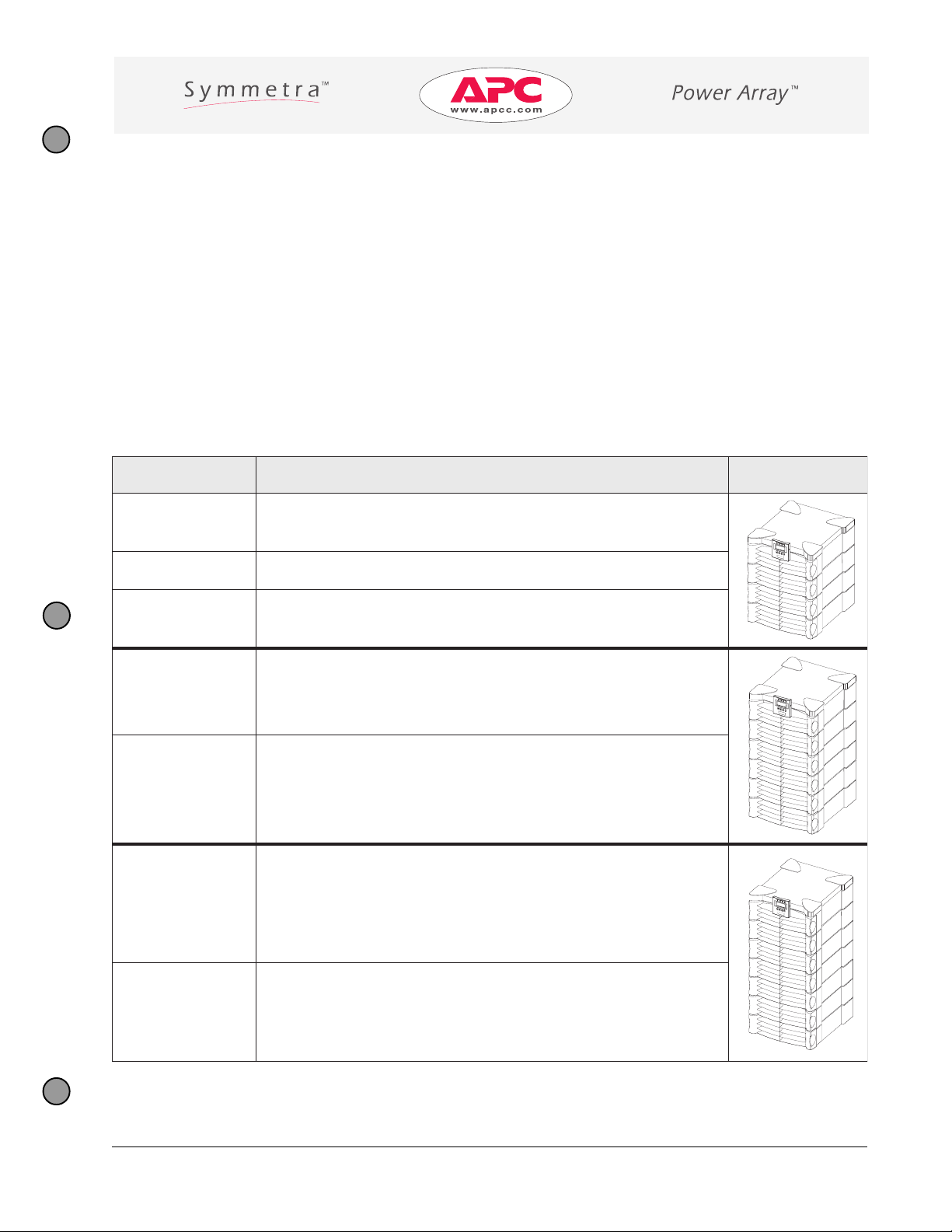
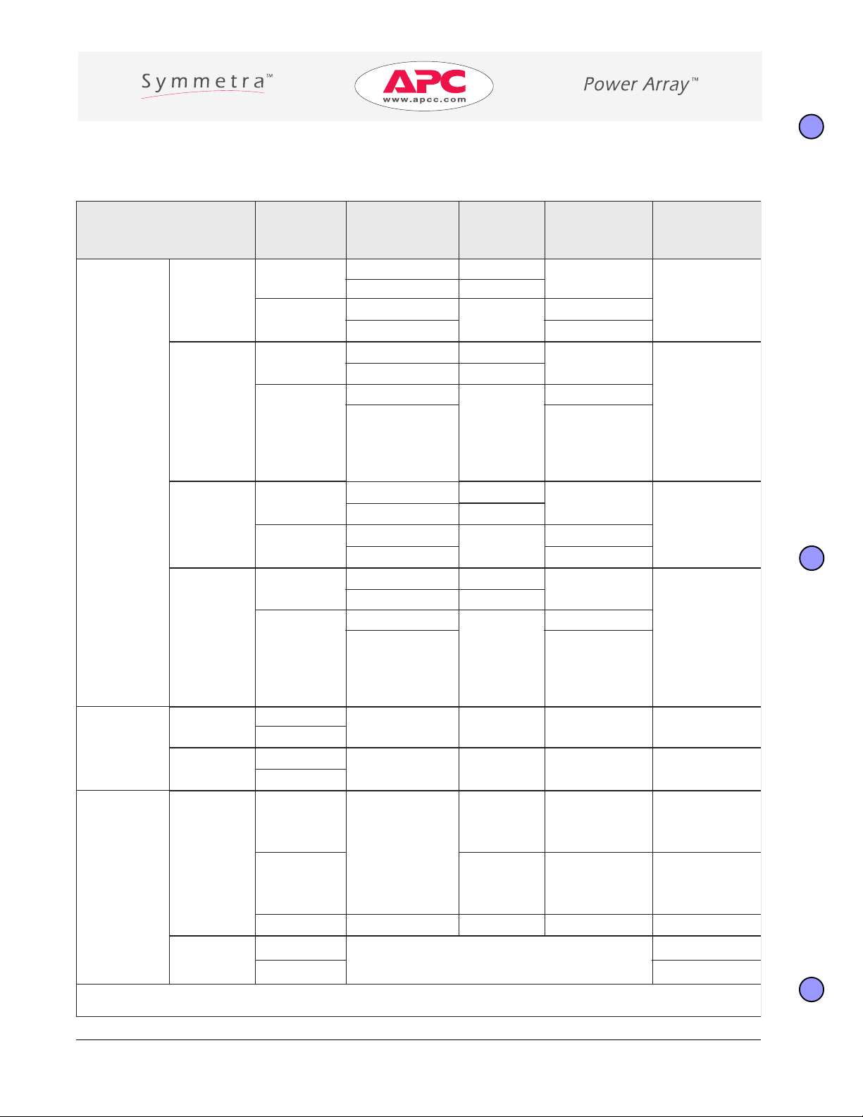
Models
SymmetraTM systems can be ordered in a variety of configurations. All of these are built around one of the
frames listed below. Refer to the packaging list or the frame name plate to determine the frame model.
ledoMemarF noitpircseD noitartsullI
FINIMYS
DP-FINIMYS .selcatpecernoitubirtsidrewopsedulcnitubevobasaemaS
IFINIMYS
IFRTSMYS
I3FRTSMYS
FRTSMYS
zH06/esahPelgniS/mumixaMAVk8
V042/V802/V021:tuptuOV042roV802:tupnI
zH06rozH05/esahPelgniS/mumixaMAVk8
tupnisaemaS:tuptuOV042ro032roV022:tupnI
zH06rozH05/esahPelgniS/mumixaMAVk61
tupnisaemaS:tuptuOV042roV032roV022:tupnI
zH06rozH05/mumixaMAVk61
83
esahPeerhT:tupnI
V514roV004roV0
V042roV032roV022esahPelgniS:tuptuO
zH06/esahPelgniS/mumixaMAVk61
V042/V802/V021:tuptuOV042roV802:tupnI
990-7163-001
DP-FRTSMYS .selcatpecernoitubirtsidrewopsedulcnitubevobasaemaS
Introduction - Page 1
Page 8
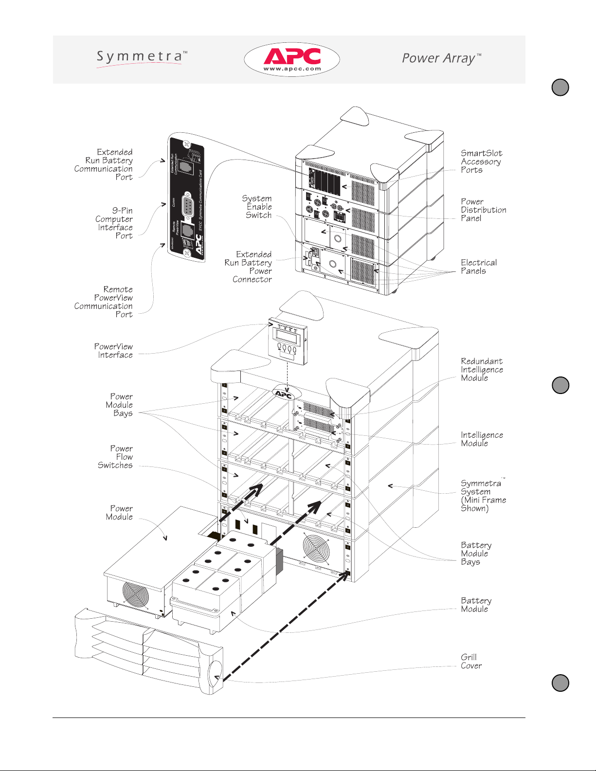
System Components
Page 2 - Introduction
990-7163-001
Page 9
MT
artemmyS
eludoMrewoP
tnenopmoC noitpircseD
.emarf
MT
artemmySehtotnisedilS.tinugnissecorprewoptnerrucgnitanretlaAVk4A
eludoMyrettaB
)MIM(eludoMecnegilletnIniaM
MT
artemmyS
MT
artemmySehtfoecnegilletniehT
.semarfyrettabnuRdednetxEemosdna,emarf
.snoitcnufnoitacinummoc
eludoMecnegilletnItnadnudeR
)MIR(
MT
MT
artemmyS
emarFmetsyS
artemmySehT
.metsys
sehctiwSwolFrewoP
)s(rekaerBtiucriCtupnI
hctiwSssapyBecnanetniaM
.sliated
revoCllirG
.wolfrewopSPUehtgnitpurretni
MT
artemmySehtotrewopetaluger)s(rekaerbtiucrictupniehT
artemmySehtsessapybhctiwSssapyBecnanetniaMeht,noitisop
MT
artemmySehtfotnorfehtotspanS
.emarf
aotnisedilS.erusolcnecitsalpaedisnidesuohgnirtsyrettabCDV021A
dnalortnoc,gnirotinomllasmrofreP.metsys
tuohtiwelbappaws-tohebotMIMehtswollA.MIMehtfonoisrevtnadnuderA
ehtfostnenopmocraludomehtrofesabehtsasevresemarf
MT
"no"ehtninehW.
stcennocdna
rofsmargaidledomcificepseeS.ecruosrewopytilituehtotyltceridtnempiuqedaol
n .ecafretniweiVrewoPetomeragnitcennocroftropA
stroPnoitacinummoC
n etuhcrewoPCPAroftropecafretniretupmocnip-9A sulP .erawtfos
n .sledomemarfyrettabnuRdednetxEemosroftropnoitacinummocA
stroPyrosseccAtolStramS
lenaPnoitubirtsiDrewoP
).elbacilppaerehW(
hctiwSelbanEmetsyS
MT
artemmyS
.emarf
daoleht nehW).weiVrewoPehtgnisuybdeussisidnammoc"nOdaoLnruT"ehT(.
lanoitporofdedivorperastropruoF tolStramS
MT
.seirossecca
ehtfokcabehtotnitnempiuqedaolgniggulproflenapnoitubirtsidrewoP
MT
artemmySeht,noitisop"no"ehtninehW
,yllanretnipusrewop rewoptonseodtub
.yllanretninwodsrewopmetsyseht,noitisop"ffo"ehtni
990-7163-001
rewoPyrettaBnuRdednetxE
rotcennoC
slenaPlacirtcelE
lenaPsseccAgniriWOPE
lenaPsseccAgniriWtupnI
.slenap
.sliatedrofsmargaidledomcificepseeS
.noitcennocrewopemarfyrettabnuRdednetxEnA
esehtdnihebsnoitcennoclanimrettuptuO/tupnIdnagniriwffOrewoPycnegremE
slenaPsseccAgniriWtuptuO
Introduction - Page 3
Page 10
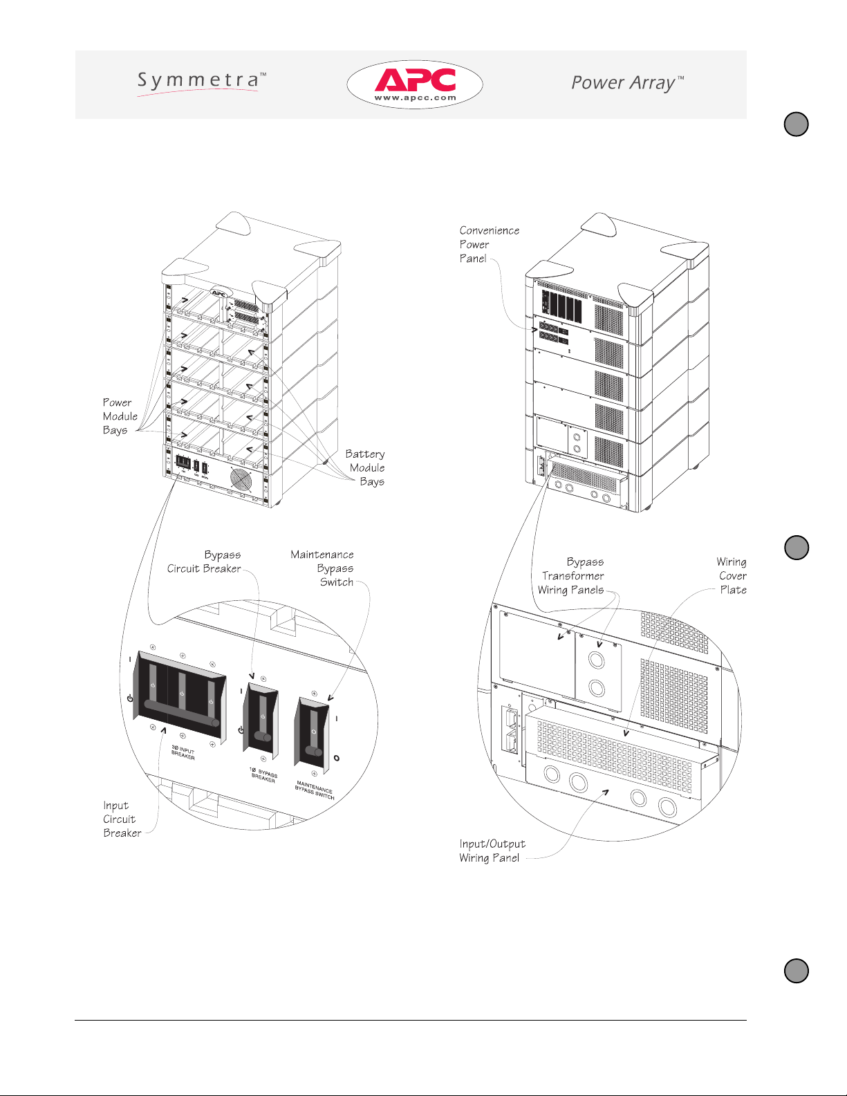
Model Specific Details (SYMSTRF3I)
Page 4 - Introduction
990-7163-001
Page 11
MT
artemmyS
stnenopmoC
:ledoMoTcificepS
noitpircseD
I3FRTSMYS
:etoN .ylnoI3FRTSMYSledomotseilppaelbatsihT
rekaerBtiucriCtupnI
.edomenilnoehtninehwsdaolrevoemertxe
slenaPgniriWtuptuO/tupnI
slenaPgniriWremrofsnarTssapyB
lenaPrewoPecneinevnoC
.slenapesehtdniheb
.stuptuomumixampmA01otdetcetorp,sgulpruof
rekaerBtiucriCssapyB
hctiwSsssapyBecnanetniaM
.tnempiuqedaoleht
tsniagametsysehtstcetorP.ecruosrewopytilituehtotartemmySstcennoC
ehthtiwxobseirosseccaehtnideppihseraetalprevocdnalenapgniriwehT
.artemmySehtgniriwnehwesehtsllatsninaicirtceleehT.launamresu
detacolkcolbnoitcennoclanimretaotderiwsiremrofsnartssapyblanoitponA
fostesowtnidegnarrA.)V042-V022(steltuorewopepyt31C023CEIthgiE
metsysehtstcetorP.dellatsnisinoitporemrofsnartssapybonnehwdesuylnO
siremrofsnartssapybafI.edomssapybninehwsdaolrevoemertxetsniaga
.hctiwssihtrevodellatsniebtsumetalprevoca,metsysehthtiwdedulcni
hctiwsssapybecnanetniamehtnehW.noitcnufssapybehtfolortnoclaunaM
otecruosrewopytilitumorfyltceriddereviledsirewop,noitisop"no"ehtnisi
990-7163-001
Introduction - Page 5
Page 12
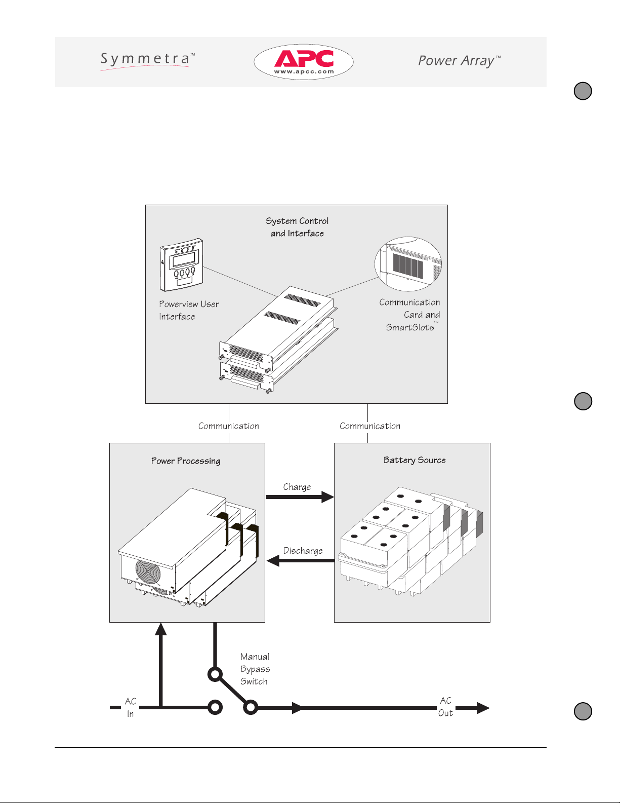
Basic Operation
The internal architecture of the SymmetraTM system is comprised of a control and interface system (intelligence
modules and several user interface options) that monitors and controls a power processing system (power
modules) and a battery source (battery modules). The relationship between these functional components is
illustrated below.
Page 6 - Introduction
990-7163-001
Page 13
Glossary of SymmetraTM Terms
Extended Run Battery Frame - An accessory that increases the battery capacity of a system. Multiple
Extended Run frames can be connected to a single SymmetraTM to significantly increase run time.
Hot-Swappable - Modules are “hot-swappable” when they can be replaced safely while the load equipment is
still powered and the Symmetra
TM
is fully functional.
N+1 - Refers to the level of power module redundancy. “N” represents the number of power modules required
to power the load, and “+1, +2, etc.” represents the number of extra power modules that are installed. For
example, a 7.3 kVA load requires two power modules for adequate protection. If the Symmetra
TM
is configured
with only two modules, it has an “N+0” level of redundancy, or no redundancy. If the system is configured with
three power modules, it has an “N+1” redundancy. Depending on the the load requirements, SymmetraTM can
be configured with 2, 3 or even 4 extra power modules, giving it an N+2, N+3, or N+4 level of redundancy.
Redundancy - Refers specifically to power modules. If at least one “extra” power module is installed, the
system can sustain a fault condition and still provide protection to the load equipment. To be fully redundant,
the system should be configured with at least one redundant power module, and a minimum of two battery
modules. (When two or more battery modules are present, one of them can fail and the system will still have a
battery power source. The total number of battery modules determines the length of on-battery run time.)
Scalability - The modular architecture allows the user to increase power capacity as load requirements increase. Scalability is limited by the size of the frame, and the number of available power module bays.
SmartSlot
cards. Before installing any SmartSlot
n Share-UPS
n PowerNet
n Measure-UPS
n Call-UPS
TM
Accessories - SmartSlotTM bays at the rear of the frame accommodate up to four accessory
TM
- Provides automatic shutdown of up to two additional servers.
TM
SNMP - Provides network UPS management.
TM
II - Provides environmental information such as ambient temperature and humidity.
TM
- Works with an external modem to provide out-of-band UPS management.
TM
accessory, ensure it is a compatible “Symmetra
TM
OK” model.
System Capacity - The maximum output power that a Symmetra
TM
system can deliver. System capacity is
limited by the lesser of the frame size, or the capacity of the installed power modules.
n A Mini Frame (8kVA) with one power module installed (4kVA) has a system capacity of 4kVA.
n A Master Frame (16kVA) with five power modules (20kVA) has a system capacity of 16kVA.
990-7163-001
Introduction - Page 7
Page 14
Page 8 - Introduction
990-7163-001
Page 15
Site Requirements
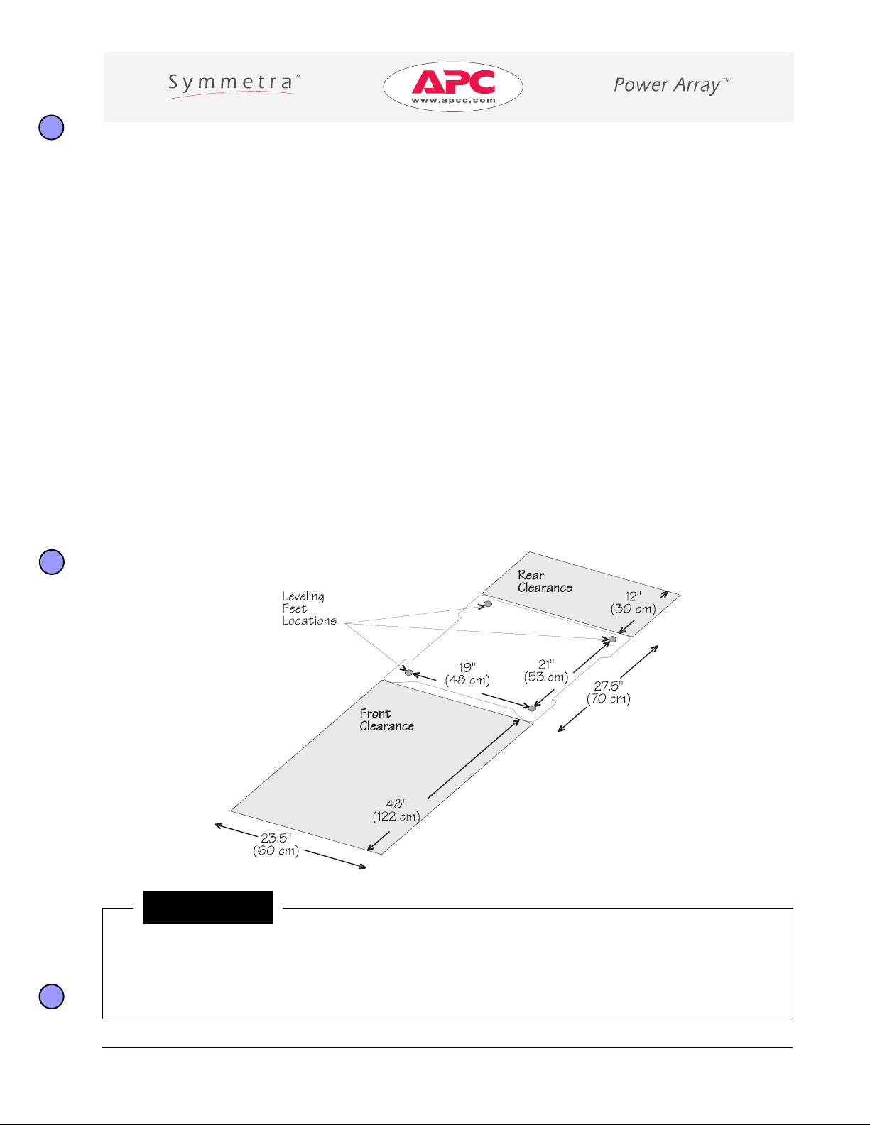
Operating Space Requirements
The SymmetraTM is 23.5” (60cm) wide, and 27.5” (70cm) deep. No space is required on the sides of the
SymmetraTM frame.
Rear Clearance
n A minimum of 12" (30 cm) of clearance is required behind the frame for adequate airflow.
n The system enable switch must remain accessible.
n The back of the Symmetra
Front Clearance
n A minimum of 48" (122 cm) of clearance is required in front of the frame.
n The PowerView interface must remain accessible.
n The front of the Symmetra
TM
must be accessible for the electrician to install wiring.
TM
must be accessible to install and replace power and battery modules.
Notice!
n The voltage transformer in the SYMINIF and SYMSTRF models emits an electro magnetic field (EMF)
that can interfere with the normal function of a computer monitor. Do not install these models in
close proximity to a computer monitor. The EMF is not of sufficient magnitude to cause interference
with other equipment.
990-7164-001
Site Requirements - Page 1
Page 16
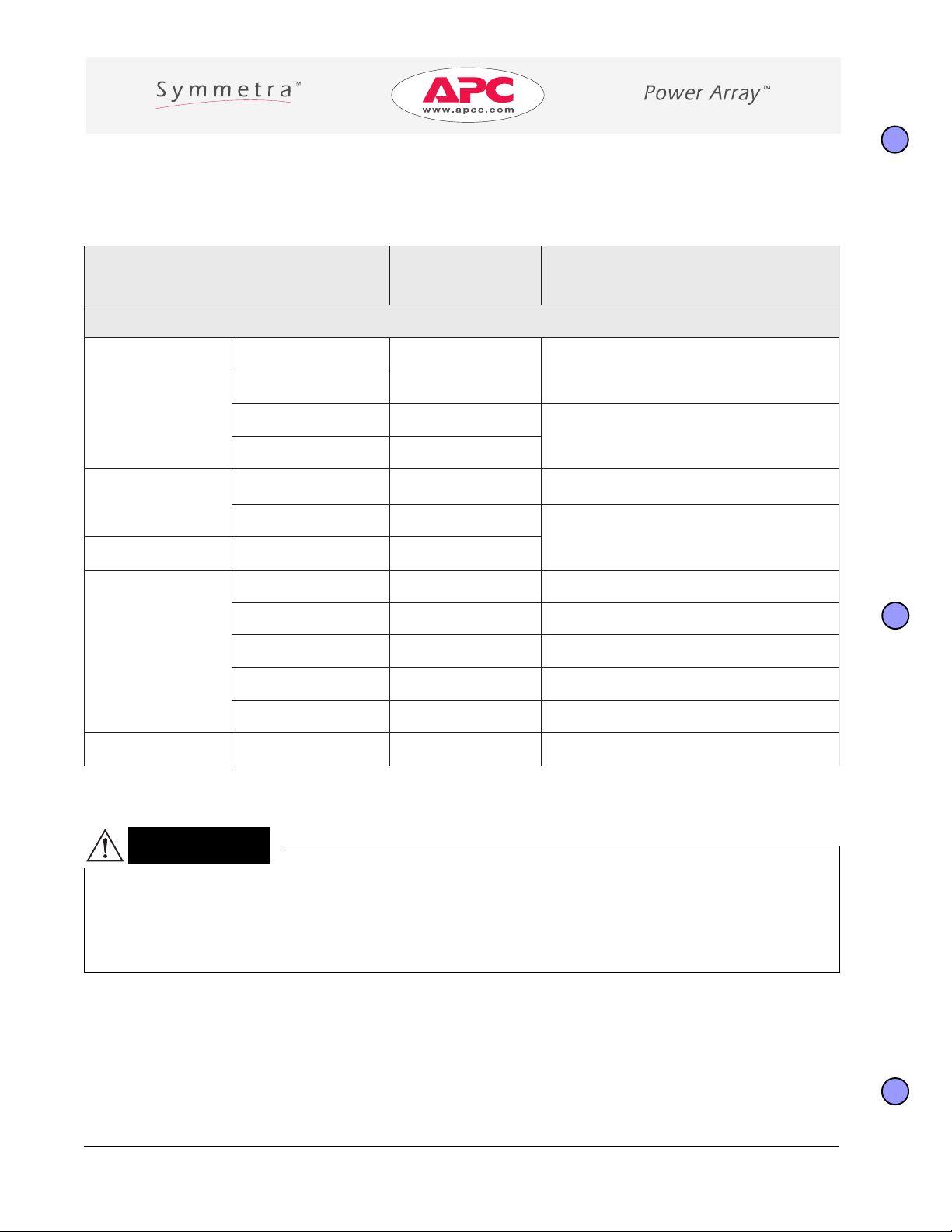
Structural Requirements
SymmetraTM components are heavy. Use this table to determine the total weight of the system.
MT
artemmyS
tnenopmoC
thgieW
)gk(bl
snoisnemiDtcudorP
)mc(sehcniHxDxW
:etoN .seludomhtiwdedaolyllufsemarfroferanwohssthgieW
FINIMYS)gk922(bl094
5.72x"5.32)68x07x06("43x"
naciremAhtroN
sledoM
DP-FINIMYSbl594gk522()
FRTSMYS)gk414(bl019
)041x07x06("55x"5.72x"5.32
DP-FRTSMYS)gk024(bl529
lanoitanretnI
sledoM1:1
IFINIMYSbl063gk461() 5.72x"5.32)68x07x06("43x"
IFRTSMYSbl056gk592()
5.72x"5.32)221x07x06("84x"
ledoM1:3
I3FRTSMYSbl556gk892()
4RXYSMB-1(bl023gk54) "5.72x"5.32)15x07x06("02x
dednetxE
yrettaBnuR
emarF
snoitpO
21RXYSMB-bl039gk324() 5.72x"5.32)221x07x06("84x"
1CBRXYSbl068gk193() )901x48x16("34x"33x"42
2CBRXYSbl0651gk907() )901x48x201("34x"33x"04
3CBRXYSbl003,2gk540,1() )251x48x201("06x"33x"04
snoitpOrehtO
RMFXPB-YSbl002gk19() )46x46x64("52x"52x"81
Caution!
n The weight of the SymmetraTM frames rest on four 1.5" (3.8 cm) diameter leveling feet. Ensure the floor
and subfloor is structurally sound to support the weight of the SymmetraTM frame(s) when concentrated on the leveling feet. Also, make sure the structure can support the total weight of all Symmetra
frames, extended run battery frames, and all other options.
Page 2 - Site Requirements
TM
990-7164-001
Page 17
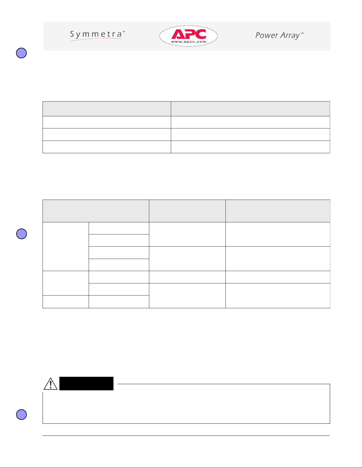
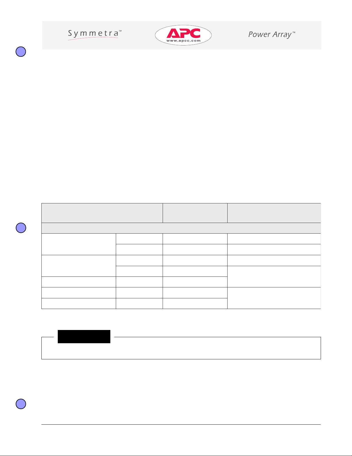
Environmental Requirements
Install SymmetraTM in a temperature controlled, clean, dry, and protected indoor area that is free of conductive
contaminants. The environment must have adequate airflow, and be free of corrosive fumes.
noitidnoClatnemnorivnE egnaRelbatpeccA
erutarepmeT)C°04-C°0(F°401-F°23
ytidimuHevitaleRgnisnednoc-non%59-0
noitavelE )m840,3ot0(levelaesnaemevobateef000,01ot0
Heat Output
Heat output of the SymmetraTM is significantly increased when batteries are charging. Battery recharge periods
are relatively infrequent.
MT
artemmyS
htroN
naciremA
sledoM
lanoitanretnI
sledoM1:1
ledoM1:3
tnenopmoC
FINIMYS
DP-FINIMYS
FRTSMYS
DP-FRTSMYS
IFINIMYS123,2875,7
IFRTSMYS
I3FRTSMYS
tuptuOUTB
)degrahCseirettaB(
314,3076,8
628,6046,51
246,4654,31
tuptuOUTB
)gnigrahCseirettaB(
Short-Term Battery Module Storage Requirements
Battery modules must be temporarily stored until the electrical wiring is connected and the SymmetraTM is
ready to be powered.
n Batteries should be stored at 0°F to 77°F (-18°C to 25°C) to preserve battery life.
n Storage environment can be within 0 to 100% relative humidity , non-condensing.
Note: Condensation will cause corrosion of electronic and chassis parts.
Caution!
n Installing battery modules in a SymmetraTM that is not powered will discharge the batteries and could
damage them permanently. Do not install battery modules into the SymmetraTM frame until after the
electrical wiring connections have been made, and the system is ready to be powered.
990-7164-001
Site Requirements - Page 3
Page 18
Electrical Requirements - Input/Output
MT
artemmyS
tnenopmoC
gniriW
tupnI
FINIMYS
tuptuO
tupnI
egatloV
)CAV(
V802A04
V042A53
V042/V021
V042/V802/V021eloP-3pmA05
V802A04
V042A53
tnerruC
daoLlluF
A04
V042/V021
DP-FINIMYS
tuptuO
V042/V802/V021
A04
htroN
naciremA
sledoM
FRTSMYS
DP-FRTSMYS
tupnI
tuptuO
tupnI
tuptuO
V802A08
V042A07
V042/V021
V042/V802/V021eloP-3pmA001
V802A08
V042A07
V042/V021
V042/V802/V021
A08
A08
tnerrucrevO
noitcetorP
)lanretxE(
muminiM
eziSeriW
eloP-1pmA05
2
mm01(GWA8#
eloP-2pmA05
)
eloP-1pmA05
eloP-2pmA05
2
)
tnerrucrevO
mm01(GWA8#
tliubsinoitcetorp
rewopehtotni
lenapnoitubirtsid
.tuptuollarof
eloP-1pmA001
2
mm52(GWA3#
eloP-2pmA001
)
eloP-1pmA001
eloP-2pmA001
2
)
tnerrucrevO
mm52(GWA3#
tliubsinoitcetorp
rewopehtotni
lenapnoitubirtsid
.tuptuollarof
lanoitanretnI
IFINIMYS
sledoM1:1
IFRTSMYS
tuptuO
tupnI
tuptuO
tupnI
ssapyBhtiw
remrofsnarT
tupnI
I3FRTSMYS
lanoitanretnI
ledoM1:3
tupnI
ssapyBtuohtiw
remrofsnarT
tuptuOV042roV032,V022A08eloP-1pmA001mm52(GWA3#
ssapyB
gnicnalaB
remrofsnarT
tupnI
tuptuO mm52(GWA3#
,V022
V042roV032
,V022
V042roV032
A04eloP-1pmA05mm01(GWA8#
A08eloP-1pmA001mm52(GWA3#
2
)
2
)
esahP/A62
,enilnonehw
dna1LnoA05
,V083
V514roV004
ssapybni2L
esahP/A62
,enilnonehw
1LnoA08
eloP-3pmA06mm01(GWA8#
eloP-3pmA001mm52(GWA3#
2
)
2
)
ssapybni
2
)
2
mm01(GWA8#
.emarfmetsysybdellortnoC
MT
artemmySehtmorf)m51('05nahtrehtrufonremrofsnartgnicnalabssapybehtllatsnI*
.
*)
2
*)
.eguageriwgnitcelesnehwpordegatlovnirotcaf,deriuqersiecnatsidretaergafI
Page 4 - Site Requirements
990-7164-001
Page 19
Electrical Requirements - EPO Switch
The SymmetraTM Power Array can be connected to either a dry contact or 24Vdc Emergency Power Off switch.
The terminal connections for the EPO switch are physically isolated from the primary circuitry of the Power
Array system.
EPO Specifications
The EPO circuit is considered a Class 2 and SELV circuit.
SELV is an acronym for “Safety Extra Low Voltage.” SELV is a common term in Europe and IEC standards. A
SELV circuit is isolated from primary circuitry through an isolating transformer and designed so that under
normal conditions, the voltage is limited to 42.4 Vpeak or 60 Vdc.
A Class 2 Circuit is a common term in North America and in UL and CSA standards. It is defined in the
Canadian Electrical Code (C22.1, Section 16) and in the National Electrical Code (NFPA 70, Article 725).
SELV and Class 2 circuits must be isolated from all primary circuitry. Do not connect any circuit to the EPO
terminal block unless it can be confirmed that the circuit is SELV or Class 2. If there is a question, use a contact
closure switch. Use one of the following cable types to connect the Symmetra
CL2 - Class 2 cable for general purpose use.
CL2P - Plenum cable for use in ducts, plenums, and other space used for environmental air.
CL2R - Riser cable for use in a vertical run in a shaft or from floor to floor.
CL2X - Limited Use cable for use in dwellings and for use in raceway.
For installation in Canada, the cable should be CSA Certified, type ELC (Extra-Low-Voltage Control Cable).
TM
to the REPO switch:
990-7164-001
Site Requirements - Page 5
Page 20

Electrical Wiring Overview
Page 6 - Site Requirements
990-7164-001
Page 21
Receiving and Unpacking
Receiving the Symmetra
The SymmetraTM Power Array frame and modular components are shipped on a number of pallets, dependant on
the configuration ordered. Verify that labeled boxes match the purchase order. Consider the system component
shipping weights and dimensions before moving them. If power modules are missing, check the frame. The
power modules may have been pre-installed at the factory.
TM
Inspect Packaging
Inspect packaging for signs of mishandling. If damage is detected:
1. Note the damage on the Bill of Lading.
2. File a damage claim with the shipping agent within 24 hours.
3. Notify APC of the damage claim, and condition of the equipment.
MT
artemmyS
:etoN S
naciremAhtroN
sledoM
lanoitanretnI
sledoM1:1
ledoM1:3
tnenopmoC
FINIMYS)gk251(bl533)701x67x48("24x"03x"33
FRTSMYS)gk462(bl085)061x67x48("36x"03x"33
IFINIMYS)gk39(bl502)701x67x48("24x"03x"33
IFRTSMYS)gk341(bl513
I3FRTSMYS)gk541(bl023
)gk(bl
thgieWgnippihS
.seludomonhtiwsemarfroferanwohssthgiewgnippih
snoisnemiDgnippihS
)mc(sehcniHxDxW
)241x67x48("65x"03x"33
eludoMyrettaB
eludoMrewoP
TTABYSbl07gk23()
MPYS)gk81(bl04
Notice!
n If power modules were pre-installed, add their weight to the SymmetraTM frame weight.
990-7165-001
Receiving and Unpacking - Page 1
1x"13x"3134x97x33("7)
Page 22

Moving The SymmetraTM Frame and Modules
The frame (bolted to the pallet), should be positioned with a pallet jack or a fork lift. Leave enough space to
unpack the frame, install the ramp, and for two people to roll it onto the floor. The SymmetraTM frame can be
moved over a flat, smooth floor surface by rolling it on the frame casters. The individually boxed power and
battery modules should be stacked close to the installation site.
Caution!
n Do not install battery modules into the SymmetraTM frame until after electrical wiring connections have
been made, and the system is ready to be powered.
n If battery modules are to be stored for an extended time, store them in a dry, cool environment.
n Battery modules are heavy (70 lb). Two people are required to carry, move and install them.
Page 2 - Receiving and Unpacking
990-7165-001
Page 23

Unpacking the SymmetraTM Frame
1. Remove packaging materials and the grill covers. Use care to prevent scratching the surface of the frame.
2. Locate the pallet ramp that is shipped beneath the top corrogated shipping cover.
3. Follow the steps below to remove the frame from the pallet. After unpacking, carefully roll the Symmetra
the installation site. It is now ready to be wired.
TM
to
Caution!
n Two people are required to remove the frame from the pallet.
TM
n All four leveling feet at the base of the Symmetra
from the pallet.
n If rolling the frame on the casters over objects such as door thresholds or floor irregularities, be careful to
prevent the frame from tipping.
990-7165-001
frame must be fully retracted before rolling the frame
Receiving and Unpacking - Page 3
Page 24

Page 4 - Receiving and Unpacking
990-7165-001
Page 25

Electrical Installation
Model: SYMSTRF3I
The following procedures must be performed by a qualified electrician!
Wiring the three phase SYMSTRF3I SymmetraTM includes:
1. Connecting 380V, 400V, or 415V three phase input wiring from a dedicated circuit
2. Connecting 220V, 230V, or 240V single phase output wiring to load equipment via a distribution panel
3. Connecting an Emergency Power Off (EPO) switch
4. Connecting an optional Bypass Balancing Transformer
Notice!
n All power and control wiring must be installed by a qualified electrician.
n Input, Output, Emergency Power Off , and Bypass Transformer wiring must comply with all applicable
local and country codes.
n It is recommended that input electricity for the Symmetra
source. (There are no other circuits on the line.)
n It is recommended that flexible metal conduit be used for all wiring connections. Place the Symmetra
in the final operating position when determining the length of flexible conduit.
n Read this section
completely before installing any wiring to the SymmetraTM frame.
TM
be provided from a dedicated utility power
TM
Warning!
n Verify that all incoming line voltage (utility power) and low voltage (control) circuits are de-energized,
and locked out, before installing cables or making connections, whether in the junction box or to the
SymmetraTM Power Array.
n Verify that all battery modules are removed from the frame, and all Extended Run battery frames are
disconnected from the Power Array before making any wiring connections to the Symmetra
n Always follow the Total Power Off Procedure before making wiring connections to or from a function-
ing Symmetra
990-7166-001
TM
Power Array. (See the Safety Information section.)
Electrical Installation - Page 1
TM
.
Page 26

Electrical Requirements
MT
artemmyS
tnenopmoC
I3FRTSMYS
lanoitanretnI
gniriW
tupnI
ssapyBhtiw
remrofsnarT
tupnI
ssapyBtuohtiw
remrofsnarT
ledoM1:3
tuptuO
ssapyB
gnicnalaB
remrofsnarT
tupnI
tuptuO mm52(GWA3#
egatloV
)CAV(
,V004,V083
V514ro
,V032,V022
V042ro
tnerruC
daoLlluF
nehwesahP/A62
noA05,enilno
ni2Ldna1L
ssapyb
nehwesahP/A62
noA08,enilno
ssapybni1L
A08eloP-1pmA001mm52(GWA3#
.emarfmetsysybdellortnoC
noitcetorP
eloP-3pmA06mm01(GWA8#
artemmySehtmorf)m51('05nahtrehtrufonremrofsnartgnicnalabssapybehtllatsnI*
.eguageriwgnitcelesnehwpordegatlovnirotcaf,deriuqersiecnatsidretaergafI
tnerrucrevO
)lanretxE(
eloP-3pmA001mm52(GWA3#
MT
.
muminiM
eziSeriW
2
)
2
)
2
)
2
mm01(GWA8#
2
EPO Switch Wiring (Required)
The SymmetraTM Power Array is to be connected to either a dry contact or 24Vdc Emergency Power Off (EPO)
switch. The terminal connections for the EPO switch are physically isolated from the primary circuitry of the
Power Array system.
*)
*)
EPO Specifications
The EPO circuit is considered a Class 2 and SELV circuit.
SELV is an acronym for “Safety Extra Low Voltage.” SELV is a common term in Europe and IEC standards. A
SELV circuit is isolated from primary circuitry through an isolating transformer and designed so that under
normal conditions, the voltage is limited to 42.4 Vpeak or 60 Vdc.
A Class 2 Circuit is a common term in North America and in UL and CSA standards. It is defined in the Canadian
Electrical Code (C22.1, Section 16) and in the National Electrical Code (NFPA 70, Article 725).
SELV and Class 2 circuits must be isolated from all primary circuitry. Do not connect any circuit to the EPO
terminal block unless it can be confirmed that the circuit is SELV or Class 2. If there is a question, use a contact
closure switch. Use one of the following cable types to connect the Symmetra
CL2 - Class 2 cable for general purpose use.
CL2P - Plenum cable for use in ducts, plenums, and other space used for environmental air.
CL2R - Riser cable for use in a vertical run in a shaft or from floor to floor.
CL2X - Limited Use cable for use in dwellings and for use in raceway.
For installation in Canada, the cable should be CSA Certified, type ELC (Extra-Low-Voltage Control Cable).
Page 2 - Electrical Installation
TM
to the EPO switch:
990-7166-001
Page 27

Electrical Wiring Overview
990-7166-001
Electrical Installation - Page 3
Page 28

Input/Output Wiring
I/O Wiring Schematic
Page 4 - Electrical Installation
990-7166-001
Page 29

Input/Output Wiring Procedure
1. Mount the Input/Output Wiring Panel to the lower rear frame panel.
Note: The I/O wiring panel and the cover plate are shipped in the frame accessory package located in the upper
TM
right module bay of the frame. Remove the four mounting screws from the rear of the Symmetra
frame, and use
them to install the panel. Place the cover plate aside.
2. Attach flexible metal conduit to the wiring panel.
Note: If the pre-installed knock-outs do not fit your strain relief hardware, use existing knock-out as a pilot to
create a new hole.
3. Pull the wire through the conduit. Leave enough wire extending from the conduit strain relief to reach
terminal blocks.
4. Strip approximately 1/2” (13 mm) of insulation from the end of each wire.
5. Connect the ground wires to the green/yellow grounding terminal block connections.
Note: Both input and output grounds attach to the same terminal block. Make sure to wire them correctly.
6. Connect the neutral wires to terminal block connections marked “N” in blue.
Caution!
n Tighten screws to ensure good electrical connection.
7. Connect remaining power wires to terminal block connections.
8. Inspect wiring for proper connections.
Note: Do not mount the wiring cover plate until the wiring verification procedure is complete.
1
2
3
A
B
C
D
E
990-7166-001
gniriW lobmyS noitpircseD
dnuorGtuptuO
!dnoceSllatsnI
lartueNtuptuO
!htruoFllatsnI
esahPtuptuO
dnuorGtupnI
N
1L
!tsriFllatsnI
lartueNtupnI
!drihTllatsnI
esahPtupnI
tupnIesahP
tupnIesahP
N
3L
2L
1L
muminiM
eziSeriW
)wolleY/neerG(dnuorGytefaS
2
mm52(GWA3#
)eulB(nruteRtuptuO
rewoPtuptuO
)wolleY/neerG(dnuorGytefaSyramirP
)eulB(nruteRtupnI
rewoPtupnI
rewoPtupnI
rewoPtupnI
Electrical Installation - Page 5
.dellatsni
)
2
afi)
mm01(GWA8#
siremrofsnartssapyb
2
mm52(GWA3#
afi)
siremrofsnartssapyb
.dellatsniton
Page 30

Emergency Power Off Switch Wiring (Required)
EPO Wiring Schematic
12
Page 6 - Electrical Installation
990-7166-001
Page 31

Emergency Power Off Switch Wiring Procedure
1. Remove EPO wiring access panel.
2. Determine the type of EPO switch to be used: A contact closure or 24V dc. If a 24V dc EPO switch will be
used, remove the factory installed jumper.
4. Attach flexible conduit, or appropriate wire/strain relief to panel.
5. Pull the wire through the conduit. Leave enough wire extending from the conduit strain relief to reach
terminal blocks.
6. Strip approximately 1/2” (13 mm) of insulation from both wires. Secure a wire terminal to each wire.
Note: It is recommended that ring terminals (crimped) be used to ensure good electrical connection.
7. Connect wires as shown according to switch type.
8. Inspect wiring to ensure proper connections. Carefully fold wiring into the entry compartment and remount
the access panel.
990-7166-001
Electrical Installation - Page 7
Page 32

Bypass Balancing Transformer Wiring (Optional)
Balancing Transformer Wiring Schematic
Page 8 - Electrical Installation
990-7166-001
Page 33

Bypass Balance Transformer Wiring Procedure (Optional)
1. Remove the transformer wiring panels on the SymmetraTM frame, and on the back of the transformer.
2. Move the jumper bar on the frame terminal block up one position. See illustration.
3. Pull the wire through the conduit. Leave enough wire extending from the conduit strain relief to reach
terminal blocks.
Note: The input wires must
4. Attach flexible metal conduit to the Symmetra
wiring panel onto the Symmetra
not be in the same conduit as the output wires. See wiring schematic.
TM
TM
frame.
wiring panel and to the transformer frame . Remount the
5. Strip approximately 1/2” (13 mm) of insulation from the end of each wire.
6. Connect the ground wire to the green/yellow grounding terminal block connection.
7. Connect the neutral wires to terminal block connections marked “N” in blue.
8. Connect remaining power wires to terminal block connections.
9. Inspect wiring to ensure proper connections.
Caution!
n Fasten connection screws to ensure good electrical connection.
10. Remount the wiring panels onto the
TM
Symmetra
11. Switch the bypass circuit breaker to the on
(I) position and install the cover plate over it.
See illustration.
Note: Installing the bypass transformer option
removes the bypass circuit breaker from the
power path.
frame and the transformer.
1
2
3
A
B
990-7166-001
gniriW lobmyS noitpircseD
esahPtuptuOrewoPtuptuO
lartueNtuptuO
dnuorGytefaS)wolleY/neerG(dnuorGytefaS
tupnIesahP
tupnIesahP
3
N
2L
1L
muminiM
eguaGeriW
2
mm52(GWA3#
)eulB(nruteRtuptuO
rewoPtupnI
rewoPtupnI
Electrical Installation - Page 9
)
2
mm01(GWA8#
)
Page 34

Wiring Verification Procedure
The following procedure will ensure that the SymmetraTM has been wired properly. The electrician who performed this electrical installation should complete this checklist and deliver it to the system operator.
Caution!
n Ensure all switches (system enable, maintenance bypass , input circuit breaker, and bypass circuit breaker)
are in the “off ” or “stand by” position. Ensure all load equipment is turned off or is unplugged from the
Power Array.
Note: If a bypass transformer was installed, disregard the bypass circuit breaker.
q 1. Apply power to the system input, and measure voltage at the input terminal block. Record measured
voltages below:
L1-Neutral: ______________________
L2-Neutral: ______________________
L3-Neutral: ______________________
Caution!
n Measured voltage must be between 184V and 265V. If it is not, STOP! Verify correct wiring from the
power source to the input wiring connections. Repeat step 1.
q 2. Connect the PowerView display as shown below:
q 3. Switch the input circuit breaker and bypass breaker on, then switch the system enable switch on.
Note: The system will make some clicking sounds as it powers up, and may display fault messages on the PowerView
display. Disregard these messages at this time.
Page 10 - Electrical Installation
990-7166-001
Page 35

q 4. Press the “Escape” key on the display until the top level menu screen appears. Select “Status.” Pressing the
enter key opens the voltage status screen as illustrated below.
Note: The fault light on the display may remain on. Disregard this visual indicator at this time.
q 5. Record input voltages below, and compare with measured voltages from step 1. If the two measurements
are significantly different, contact APC Symmetra
Vin1: ______________________
Vin2: ______________________
Vin3: ______________________
TM
technical support.
q 6. Switch the maintenance bypass switch on.
Note: Disregard any LED indicator or fault messages on the PowerView.
Record output voltage below, and compare with Vin1 from step 5. If the two measurements are significantly
TM
different, contact APC Symmetra
technical support.
Reported Output Voltage: Out:____________V_________Hz
q 7. Test the EPO switch. The system enable switch should physically move to the “stand by” position, and the
system should shut down completely. If this does not occur, check the connections and the EPO switch to
ensure they are installed and functioning properly.
q 8. Successful completion of steps 1 through 7 indicate that the system wiring is properly installed. Turn off
breakers and switches and shut down input power to the system. Reinstall all wiring access panels on the
frame.
Electrical Installation Completed by:__________________________________________
__________________________________________
__________________________________________
990-7166-001
Electrical Installation - Page 11
Page 36

APC Worldwide Technical Support Telephone Numbers:
APC Headquarters, US
Tel:800-800-4272
APC Argentina
Tel:0800-9-2722
APC Australia
Tel:+612-9955-9366
Fax: +612-9955-2844
Freephone:1 800 652 725
APC Austria
Tel: 0800 296480
APC Belgium
Tel:0800 15063
APC Brazil
Tel: 0800-127221
APC China
Tel:+86-10-8529-9888
Fax: +86-10-8529-9158
APC Czech Republic
Tel:0800 102063
APC Denmark
Tel:800 18 153
APC Finland
Tel:9800 13 374
APC France
Tel:0800 906 483
APC Germany
Tel:0800 1801227
APC Greece
Tel:00800 353 12206
APC Hungary
Tel: 06800 12221
APC India, Nepal,
Sri Lanka, Bangladesh,
and Maldives
Tel: +91-44-433-1124
Fax: +91-44-434-1464
APC Indonesia
Tel: +62-21-650-0813
Fax: +62-21-60-7427
APC Ireland
Tel: 1-800-702000 x2045
APC Israel
Tel: 177 353 2206
APC Italy
Tel: 800 874731
APC Japan
Tel: +813-5434-2021
Fax: +813-5434-2022
APC Korea
Tel: +82-2-501-6492
Fax: +82-2-501-6369
APC Luxembourg
Tel: 0800 2091
APC Malaysia
Tel: +603-756-8786
Fax: +603-756-8780
APC Norway
Tel: 800 11 632
APC Philippines
Tel: +63-2-813-2662
Fax: +63-2-892-2448
APC Poland
Tel:00800 353 1202
APC Portugal
Tel:0800 853 182
APC Russia
Tel:+7 095 916 7166
APC Singapore, Thailand,
Vietnam
Tel:+65-398-1000
Fax:+65-398-1010
APC South Africa
Tel: 0800 994206
APC Spain
Tel:900 95 35 33
APC Sweden
Tel: 020 795 419
APC Switzerland
Tel: 0800 556177
APC Taiwan
Tel: +886-2-2755-1945
Fax: +866-2-2755-1946
APC Turkey
Tel: 0800 353 90275
APC United Kingdom
Tel: 0800 132990
Latin America, toll free to
APC Corporate, USA:
Antigua
Tel: 800-326-0640
Bahamas
Tel: 800-788-9688
Barbados
Tel: 800-534-0631
Bermuda
Tel: 800-623-0717
Brazil
Tel: 0800-127221
Chile
Tel: 123-0-020-0254
Tel: 00-020-3255
Colombia
Tel: 980153947
Mexico
Tel: 95-800-804-4283
Tel: 001-800-788-2208
Peru
Tel: 001-800-804-4383
Uruguay
Tel: 000-413-598-2139
Tel: 1 800-788-9688
Venezuela
Tel: 8001-2856
Tel: 800-1-3506
APC Holland
Tel:0800 0224655
Page 12 - Electrical Installation
990-7166-001
Page 37

Startup Procedure
After the electrical wiring connections are verified, power and battery modules can be installed and the Symmetra
can begin to deliver conditioned power to the output power panel(s).
Securing The Frame - Setting The Leveling Feet
1. Locate the frame in its final operating position.
Note: Leave a minimum of 12” (30 cm) of clearance at the rear of the frame for adequate airflow. Make sure the
system enable switch remains accessible.
2. Hand turn all four leveling feet until the pads make contact with the floor.
3. Use a wrench to extend each leveling foot by turning the hex nut two complete turns.
4. Adjust the leveling feet until the frame is level front to back and side to side.
TM
Lower all four leveling feet
Notice!
n After the leveling feet are lowered, attempting to move the frame may bend them.
990-7167-001
Start-Up Procedure - Page 1
Page 38

Power Module Installation
1. Align the runners of a power module with the alignment grooves in the bottom module bay. Firmly slide the
power module into the frame until the “drop-lock” engages.
2. Swing the flip latch up and fasten the screw to the power module. Do not overtighten.
3. Follow this procedure to install all power modules.
Notice!
n Power modules are installed on the left, battery modules are installed on the right.
n Always install power modules into the lowest available bay.
n If the power modules were installed at the factory, remove each of the shipping retainers that secured the
modules during shipping. Secure the flip latches.
Page 2 - Start-Up Procedure
990-7167-001
Page 39

Battery Module Installation
1. With one person on each side of a battery module, align the runners of a battery module with the alignment
grooves in the bottom module bay. Carefully slide the battery module into the frame until the retaining
flange passes through the frame notch.
2. One person can now firmly push the battery module into the frame until the “drop-lock” engages.
3. Follow this procedure to install all battery modules.
Warning!
n The 120V, 7.2 Ah battery module constitutes a risk of electrical shock and an energy hazard. High short
circuit current through conductive materials could cause severe burns. Before handling battery modules, remove conductive jewelry such as chains, wrist watches and rings.
n Battery modules weigh approx. 60 lb (27 kg). Two people are required to handle battery modules.
n Always install battery modules in the lowest available bay. When removing modules, start from the
highest level and work down.
990-7167-001
Start-Up Procedure - Page 3
Page 40

System Startup Procedure
Notice!
n Refer to Appendix A for information about the PowerView Interface.
n At least one power module, one battery module, and the main intelligence module must be installed
before the system will start.
n Load equipment can be left connected during this start-up procedure, but it should be switched off
until startup is complete.
n The PowerView can be configured to display French, Italian, German or Spanish. (Appendix A, page 3.)
1. Apply input power to the system from the utility power source.
2. Switch the input circuit breaker(s) and the system enable switch on.
3. Wait approximately 15 seconds to allow the system intelligence module to boot up and complete a startup
sequence.
4. Open the top-level menu screen on the PowerView display. (See Appendix A, page 4.)
Note: The PowerView may display some “configuration change” messages because the system was configured at
the factory with a different number of power or battery modules than are now installed. Disregard these messages,
and press the escape key to close them.
5. Verify that all power, battery and intelligence modules are detected by the system and are functioning properly by reviewing all status screens on the PowerView. (From the Status menu, open status screens for battery,
power, main intelligence, and redundant intelligence modules. See Appendix A, page 5.)
Note: If a problem is reported, ensure the system component in question is properly installed. If the problem
persists, refer to the troubleshooting information in Appendix B.
6. Turn load on. (From the Control menu, click Turn Load On. See Appendix A, page 5.)
7. Replace all front grill covers. Make sure all wiring panels are firmly secured to the frame.
TM
8. The Symmetra
power needs.
system is now ready to support the load equipment and be configured to meet specific
Page 4 - Start-Up Procedure
990-7167-001
Page 41

Configuration and
Advanced Operation
Notice!
n The following information should be considered when configuring the Symmetra Power Array to pro-
vide optimal power protection for your specific requirements. For detailed settings and programming
sequences, refer to The PowerView Interface - Appendix A.
Configuration
Display Settings
n The PowerView display date/time should be set to ensure an accurate set of records in the event log. The
beeper volume and screen contrast can be adjusted to meet your particular site needs.
n A password can be used to prevent unauthorized access to configuration settings. Once a password is in-
voked, changes can be made only after entering the password.
n The Startup Screen can be customized to display information that is most important to you.
System Settings (Setup)
n Shutdown and return parameters can be set to best fit your specific power environment. Consider the time
required to gracefully shut down your equipment in the event that a power outage drains the SymmetraTM to
battery exhaustion. Also consider how and when power to the load equipment should be restored after the
utility power returns.
n Output frequency can be controlled. Full Range Tracking (default) offers the widest available range. If your
equipment requires tighter limits, consider the output frequency tolerance setting and bypass control.
n Alarm thresholds can be set to protect your selected system limits. The Symmetra will constantly self moni-
tor load output and alert you with an audible alarm and an error message displayed on the PowerView screen
if a violation occurs.
n Other settings include system self test scheduling, UPS Identification setting, output voltage, and output
voltage reporting.
Logging Control
n A log of the last 64 system events is recorded and stored in the PowerView. The log function can be configured
to record only those events important to you. The event log is especially valuable for diagnosing configuration problems.
990-7168-001
Configuration and Advanced Operation - Page 1
Page 42

Advanced Operation
Control Functions
Symmetra requires you to use the “power load on/off” function to deliver power to the load equipment. Other
control functions allow you to conduct a system self test, test/control external communications by simulating a
power failure, and command the system to go into and out of bypass mode. These functions are primarily used
during configuration changes or system maintainance.
Diagnostic Information
Symmetra constantly monitors itself for internal problems. If an error is detected, the display fault indicator will
light, and an error message will appear on the PowerView screen. Use this diagnostic information to determine
the source of the fault.
Status Review
The status of each modular component in the system - battery, power, and intelligence modules - can be individually reviewed using the PowerView. System settings can also be reviewed.
Load/Capacity changes
Over time, it is possible there will be an increased power demand placed on the Symmetra. As the power demand
increases, system capacity is decreased. Symmetra monitors this relationship and will initiate an audible alarm if
the user-defined parameters are violated. This can be rectified by the following methods:
a.) Increase system capacity by adding Power and Battery Modules.
b.) Change alarm settings to eliminate the violation.
c.) Reduce the load by disconnecting equipment.
Note: System capacity is limited by the lesser of the frame size, or the total capacity of the installed power modules.
Runtime Calibration
To ensure the Symmetra is accurately reporting the battery runtime. A Runtime Calibration test should be conducted at least once a year. The runtime calibration exercises the battery system to 50% discharge, and helps
maintain optimal battery function.
Accessories
The PowerView will communicate with SmartSlot accessories only when an auxilary power cable connects the
PowerView to the computer interface port at the rear of the Symmetra. Contact APC Technical Support for
information about this function.
Page 2 - Configuration and Advanced Operation
990-7168-001
Page 43

Appendix A
The PowerView Interface
It is easy to use the PowerView to command, monitor and configure the SymmetraTM Power Array system. The
interface is so intuitive that even first-time users get up to speed quickly.
Notice!
n The PowerView default language is English. It can be configured to display French, Italian, German or
Spanish. See page 3.
n The PowerView can be connected or disconnected without interrupting the UPS function of the
Symmetra
990-7169-001
TM
.
Appendix A - The PowerView Interface - Page 1
Page 44

PowerView Components
342
1
5
12
11
10
6
9
8
7
tnenopmoCweiVrewoP noitpircseD
1
)neerg(DELNODAOL
.rewopgniviecersitnempiuqedaolehT
2
3
4
5
6
7
8
9
01
11
21
)wolley(DELYRETTABNO
)wolley(DELSSAPYB
)der(DELTLUAF
yalpsiDDCL
dnatSpotelbaT
yeKepacsE
yeKpUllorcS
yeKnwoDllorcS
yeKretnE
mralAoiduA
pihCMORPEegaugnaL
.seludom
MT
artemmySehT
MT
artemmySehT
.mrala"peeb"astimeweiVrewoPehT
.tiucricehtmorfdessapybylevitceffesi
).BxidneppAeeS(.yalpsidciremunahplaehtnosraeppa
.yalpsidlatsyrcdiuqilciremunahplaretcarahc02x4A
.ecafrustalfanoweiVrewoPehttesotliaberiwehttuolluP
.neercssuoiverpehtotsnruteR.neercstnerrucehtstixE
.tsilahguorhtpusllorcsro,puworranoitcelesehtsevoM
.tsilahguorhtnwodsllorcsro,nwodworranoitcelesehtsevoM
.tsilnoitcelesasneporo,dnammocunemdetcelesehtsnepO
).hsilgnEsitluafeD(.hsinapSronamreG,nailatI,hcnerF,hsilgnE
yrettabehtmorfdeilppusgniebsirewoP.derruccosaheruliafrewoptupninA
.ecruosrewopytilituehtmorfyltceriddeilppusgniebsidaolehtotrewoP
egassemmralanA.noitidnoctluaflanretninadetcetedsah
Page 2 - The PowerView Interface - Appendix A
990-7169-001
Page 45

Language Configuration
To change the PowerView display language, an internal EPROM chip must be replaced.
Caution!
n The internal circuitry of the PowerView and the language EPROM chip are sensitive to static electricity.
Use all necessary precautions to eliminate static electricity from yourself and all tools before replacing
the chip. Do not remove the chip from the protective case until ready to install it in the PowerView.
n The PowerView cable must be disconnected from the PowerView before proceeding.
Language Chip Replacement Procedure
1. Remove four screws to separate the rear cover from the PowerView.
2. Locate the language EPROM chip. It is adjacent to a larger 40-pin chip. There is a semicircular notch at one end
of the language chip. The replacement chip must be oriented so that the semicircular notch is in the same position.
3. Insert a small flathead screwdriver between the language chip and the socket. Gently twist the blade to lift the
chip. Proceed with caution and patience to avoid bent pins.
4. Position the replacement language chip on the socket with the semicircular notch in the same orientation as
the original. Carefully ensure that all pins are properly aligned with the socket. Apply even pressure with fingers
to the top of the EPROM until it is fully seated in the socket. Replace the rear cover.
990-7169-001
Language
EPROM Chip
Appendix A - The PowerView Interface - Page 3
Page 46

The Startup Screen
The factory default startup screen is opened by pressing the escape key. It displays the following information:
n Fuel Percentage - the percentage of battery capacity (fuel) that is presently available.
n Load Percentage - the percentage of system capacity that is being used to supply conditioned power to
the load equipment.
n Voltage and Frequency - the input/output voltage, and the ouput frequency.
n Run Time - the run time that can be expected, based on the amount of power required by the load
equipment, and the power capacity of all battery modules connected to the Symmetra
Note: The PowerView interface will “time out” after ten minutes of inactivity, and the LCD display will go blank. The
screen display will reappear when any key is touched.
Note: The startup screen for the international single phase models is depicted. Your startup screen may vary.
TM
Power Array.
Top-Level Menu Screen
Press the escape key to open the “Top-Level Menu” screen. This screen is the “launching pad” to monitor, command and configure the system. Refer to the following tables for all PowerView commands and controls.
Note: The selection arrow in the illustration below is used to select a command. Pressing the up or down key moves the
selection arrow to the desired command, and then pressing the enter key opens it.
Page 4 - The PowerView Interface - Appendix A
990-7169-001
Page 47

lortnoC
noitcnuF
ffO/nOdaoLnruT
tseTfleSoD
eruliaFrewoPetalumiS
.tneve
.deyalpsideblliwegassemrorrena,detceted
toobeRlufecarG
.syaledemitesehttesotnwodtuhS>puteS
nO/ffOnruTlufecarG
.syaledemiteseht
noitarbilaCemitnuRtratS
ssapyBfOtuO/otnISPU
sutatS
noitcnuF
.tnempiuqedaolotecruosytilitu
neercSsutatStnerruC/egatloV
.tnempiuqedetcennocotrewoptuptuofoyreviledroflortnocmetsysehT
simelborpafI.scitsongaid-flesllahguorhtsnuR.tsetflesmetsysasetaitinI
sihtsezingocerrevresehtfitsetotdesU.nruter/eruliafrewopasetalumiS
asetaitinI.erawtfosetuhCrewoPotdetcennocebotartemmySehtseriuqeR
yrettaB-woL"denifed-resuehtretfA.nwodtuhsotrevresehtroflangis
-resuehtfonoitarudehtrofffodehctiwssirewoptuptuoeht",noitaruD
eeS.niaganodehctiwssirewoptuptuoehtnehT".yaleDnruteR"denifed
asetaitinI.erawtfosetuhCrewoPotdetcennocebotartemmySehtseriuqeR
yrettaB-woL"denifed-resuehtretfA.nwodtuhsotrevresehtroflangis
tesotnwodtuhS>puteSeeS.ffodehctiwssirewoptuptuoeht",noitaruD
tuptuodaolsrevileD.tnemerusaememitnuryrettabetaruccanasetaluclaC
.yticapacriehtfo%05otyrettabsegrahcsiD.ecruosyrettabmorfrewop
morfyltceriddereviledsirewoP.noitcnufssapybehtfolortnocmetsysehT
.noitamrofnitnerructuptuodna,egatlovtuptuo,egatlovtupnisyalpsiD
ycnadnudeRoN-daoLegatnecreP
htiW-daoLegatnecreP
ycnadnudeR
seicneuqerFtuptuOdnatupnI
neercSsutatSyrettaB
neercSsutatSeludoMrewoP
neercSsutatSsdlohserhTmralA
neercSsutatSsuoenallecsiM
tsTfleS.tsetflesfotluseryrammussyalpsiD
rfxtsL .refsnartmetsystsalehtrofnosaerehtfoyrammusasyalpsiD
sutatS .).cte,ssapyb,ttabno,enilno,.e.i(edomgnitarepotnerrucehtsyalpsiD
MIR/MI .seludomecnegilletnItnadnudeRdnaecnegilletnIfosutatsehtsyalpsiD
.seludomrewopllafoyticapaclatotehtotdaoltnerrucehtserapmoC
tpecxeseludomrewopllafoyticapaclatotehtotdaoltnerrucehtserapmoC
.dlohserhtmrala"ecnareloTtluaF"ehtybedisateseratahtseludomrewopeht
ecnarelottluafehtdna,dellatsniseludomrewopruoferaerehtfi,elpmaxeroF
rewop3ylnosesudaolfoegatnecrepsiht",1"ottessidlohserhtmrala
ehttesotsdlohserhTmralA>puteSeeS.noitaluclacehtrofseludom
.levelycnadnuder
seicneuqerftuptuodnatupniderusaemehtsyalpsiD
sutatsdna,emitnur,yticapac,egatlovecruoseludomyrettabsyalpsiD
.noitamrofni
.noitamrofnisutatsdna,ecnarelottluaf,yticapacecruoseludomrewopsyalpsiD
mralaesehttesotsmralA>puteSeeS.sgnittesmraladenifed-resuehtsyalpsiD
.sdlohserht
990-7169-001
Appendix A - The PowerView Interface - Page 5
Page 48

PowerView Commands
(continued)
puteS
nwodtuhS
ruDttaBwoL
ylDnwodtuhS
ylDnruteR
paCtaBnruteR
tluafeD
s
qerFtuptuO
smralA
ycnadnudeR
daoL .timilsihtsdeecxedaolehtnehwdnuoslliwmralaelbiduanA
noitcnuF snoitpO
.noitsuahxeyrettaboteudnwodstuhsartemmyS
dnammocnwodtuhsehtseussitahtretupmocehtfidesU
.nwodflestituhsyllufecargotemitnurlanoitiddaseriuqer
ehterofebezilibatsotrewopytilituwollaotlavretniyaled
.enilnokcabseogmetsys
a,eruliafrewopytilitudednetxenamorfgninruternehW
.daolehtgnirewopererofebyticapacyrettabmuminim
stluafedyrotcafotsgnittesllateS
.egnar
.sdlohserhtmralaehtsteS
.level
.eruliafrewopytilituafotneveehtnisretemarapnwodtuhsehtsteS
ehterofebsetunimforebmunsihtdnuoslliwmralaelbiduanA
sdnoces
a,eruliafrewopytilituaretfaderotsersirewopytilitunehW
sdnoces
sihtnihtiwtupniehtotkcolesahplliwtuptuoartemmySehT
sihtwolebsllafycnadnuderehtfidnuoslliwmralaelbiduanA
2ro1,0
)emarFiniM(
setunim01ro,7,5,2
006ro003,081,02
003ro081,06,0
%09ro,05,51,0
,zH1.-/+zH06ro05
,zH3-/+zH06ro05
gnikcarTegnaRlluF
reveN,AVk8otAVk1
reveN,AVk6otAVk1
)emarFretsaM(
emitnuR
ssapyB
ypoC
rehtO
tseTfleS
DISPU.metsysaotgnirtstxetretcarahc-nevesasngissA
tuptuO
gnitropeRtuoV
Page 6 - The PowerView Interface - Appendix A
).ylnosmetsys
).ylnosnoisrev
.muminimsihthtaeneb
MT
artemmySehthtobtahttneveylekilnuehtnI
:snoitpoesehtfoenoesoohc
.artemmyShtiwdesutoN
.sgnittesdenifed-resugniniameR
.lavretnicidoirepdeificeps
sllafemitnurelbaliavaehtfidnuoslliwmralaelbiduanA
reven
ehtdna,sliaf
,egnarlamronfoedistuosiycneuqerfenilroegatlovtupni
-resusihttaflestitsetyllacitamotuanacartemmySehT
lanoitanretnI(.egatlovtupnifosseldrageregatlovtuptuosteS
naciremAhtroN(.egatlovtuptuotnacifingistsomehtstropeR
daoLporD
54ro,03,51,01,5
,5,4,3,2,1,setunim
ro,sruoh8ro,7,6
rossapyBotoG
,syad7,nOrewoPtA
delbasiDro,syad41
V042roV032,V022
otuAro,V042,V802
990-7169-001
Page 49

PowerView Commands
seirosseccA
SPUerusaeMehtsrotinoM tolStramS .yrosseccA
(continued)
MT
artemmySehtfokcabehttatropecafretniretupmocehtotdetcennocsiweiVrewoPehtnehwdesuylnO
.emarf
gniggoL
goLweiV
scitsitatSweiV
noitcnuF
yekretneehtsserpdnayrtnenaottnioP.stneve46tnecertsomehtskcarT
.tnevetahtnonoitamrofnieromrof
nodna,stluaf,yrettabwol,yrettabotsrefsnartforebmunlatotehtsdroceR
.stneveemitnuryrettab
gniggoLerugifnoC
ffO/nO:stnevErewoP
ffO/nO:slortnoCSPU
ffO/nO:stluaFSPU
ffO/nO:ytivitcAresU
.golehtnidedrocereratahtstnevefoepytehtsteS
spuorGtnevEtsiL
stnevErewoP
stnevElortnoCSPU
seitivitcAresU
stnevEtluaFSPU
stnevESPUerusaeM
.gnitsiltnevecificepsrofswollA
990-7169-001
goLraelC
seoD.golweivehtsraelCton.stsiltneveevitcaehtraelc
Appendix A - The PowerView Interface - Page 7
Page 50

PowerView Commands
(continued)
yalpsiD
emiT/etaD
drowssaP
drowssaP.drowssapasteS dne='_',9-0,Z-A
tuoemiT.remitytivitcaninA ,setunim03ro,01,5,2,1
etadilavnI otsegnahcdezirohtuanustneverP.tceffeotnidrowssapstuP
noitcnuF snoitpO
.etaddnaemittcerrocehtteS dna)raey:htnom:yad(yy:mm:dd
.segnahcnoitarugifnocdezirohtuanutsniagastcetorP
.noitarugifnocartemmySeht
noitamrofnI
repeeB
SPUtA.artemmySehthtiwdesutoN
yalpsiDtA.weiVrewoPehtnimralaelbiduaehtrofsretemarapsteS 03+eruliaFrewoP,eruliaFrewoP
emuloVemulovmralaelbiduasteS iH,muideM,woL,ffO
kcilC.snottubyalpsidgnisserpnehwdnuoskcilcteSffO,nO
tsartnoC
tsartnocneercsDCLteS 7,6,5,4,3,2,1,0
.airetirc)repeeb(mralaelbiduasteS
)etunim:ruoh(mm:hh
.reveroFro,sruoH4ro,2,1
.noitamrofninoisiverdnaerutcafunamfoetad,rebmunlaires,rebmunledomweiVrewoPsyalpsiD
.reveN,yrettaBwoL,sdnoces
erugifnoC
Page 8 - The PowerView Interface - Appendix A
noitamrofnideyalpsidneercsputratsehtserugifnocmotsuC yrotcafesuotdednemmocersitI
tluafed
990-7169-001
Page 51

PowerView Commands
(continued)
)scitson(gaiD
scitsongaiDdnatluaF
eludoMecnegilletnI
eludoMletnItnadnudeR
P
rw
ttaB
s
seludoM
noitcnuF
.tluaftahtfonoitamrofnicitsongaiddnatluafmetsystnerrucyalpsiD
.noitamrofnidnasutatseludomecnegilletnideliatedsyalpsiD
.noitamrofnidnasutatseludomecnegilletnitnadnuderdeliatedsyalpsiD
.noitamrofnidnasutatseludomrewopdeliatedsyalpsiD
.noitamrofnidnasutatseludomyrettabdeliatedsyalpsiD
pleH
otylsuoenatlumissyek"nwoDllorcS"dna"pUllorcS"ehtsserP.yalpsidweiVrewoPehtotnitliuberasneercsplehenilnO
.plehevitisnestxetnocssecca
990-7169-001
Appendix A - The PowerView Interface - Page 9
Page 52

n The PowerV ew cable must be d sconnected from the PowerV ew before proceed ng.
Wall Mounting the PowerView
Use the template below to install the PowerView on a wall:
1. Note the four mounting slots molded into the back of the PowerView.
2. Secure four large screws on a clean dry wall surface.
3. Leave each screw extending 5/16" (8mm) out from the surface of the wall.
4. Connect the 20’ PowerView remote cable (provided) to the PowerView and to the PowerView communication
port at the rear of the Symmetra
5. Position the PowerView onto the screws.
TM
frame.
9cm (3 1/2")
Cut Here
Up
8cm (3 1/8")
Page 10 - The PowerView Interface - Appendix A
10.3cm (4")
990-7169-001
Page 53

Appendix B
Troubleshooting
The PowerView reports various messages on the display, including alarm status and changes in system configuration. This section lists all PowerView display messages, what each means, and an appropriate corrective action.
Note: More than one of these messages may occur at one time. If this happens, be sure to review all of the messages for
a better understanding of the system condition.
weiVrewoP
egasseM
pU-tratS
.NOtsalecnis
.NOtsal
ssapybrofton
degnahcseludomrwP#
MT
artemmyS
ecnisdegnahcseirettaB#
MT
artemmyS
tnadnudeRoN
.eludoMecnegilletnI
nahtsselyticapacttaB
paCttaBnruteR
edistuoqerFtupnI
egnarderugifnoc
tubSPUrofetauqedaCA
MT
artemmyS
MT
artemmyS
.elbaliava
MT
artemmySehT
gninaeM noitcAevitcerroC
neebsaheludomrewopenotsaeltA
ehtmorfdevomerro,dedda
ehtemittsalehtecnis
.deussisawdnammocNOrwP
neebsaheludomyrettabenotsaeltA
ehtmorfdevomerro,dedda
ehtemittsalehtecnis
.deussisawdnammocNOrwP
.dellatsniMIRonsierehTehttrobaro,putratsehthtiwdeecorP
:etoN ereht,MIRgninoitcnufatuohtiW
ehtfoyticapacyrettabehT
resuehtnahtsselsi
yticapacyrettabmuminimdeificeps
.daolehtnonrutotderiuqer
ehtotycneuqerftupniehT
derugifnocehtedistuosi
lliwycneuqerftuptuoehT.egnar
tupniehthtiwezinorhcnyston
tonsissapyblamroN.ycneuqerf
enilnonoitcnuflliw
ehtnitub,egatlovtupniehthtiw
eht,deriuqersissapybtahttneve
otetauqedatonsiegatlovtupni
.tnempiuqedaolehtrewop
noitpO2# lamroN.putratshtiwdeecorP:
deecorP.yrassecennoitcaevitcerrocoN
.putratsehthtiw
deecorP.yrassecennoitcaevitcerrocoN
.putratsehthtiw
.MIRallatsnidna,putrats
MIMafotneveehtniycnadnuderonsi
.eruliaf
1#noitpO wolladna,putratsehttrobA:
.egrahcerotseirettab
2#noitpO sselhtiw,putratseunitnoC:
.yticapacyrettabmuminimnaht
1#noitpO ehtfoycneuqerfehtevorpmI:
.egatlovgnimocni
2#noitpO ehtfoegnarehtnediW:
ehthtiwycneuqerfgnimocnielbatpecca
-qerFtuptuO-puteS-putratS(.weiVrewoP
).tceleS
3#noitpO lamroN.putratshtiwdeecorP:
.elbaliavatonsissapyb
1#noitpO gnimocniehtevorpmI:
.egatlov
.elbaliavatonsissapyb
990-7170-001
,tupniCAoN/woL
yrettabnoputrats
MT
artemmySeht
MT
artemmyS
.yrettab
tratsotetauqedatonsiegatlovtupnI
,sdeecorpputratsfI.
morfnoitcnuflliw
1#noitpO elbatpeccalitnuputratstrobA:
.tneserpsiegatlovtupni
2#noitpO yrettaB.putratshtiwdeecorP:
.degrahcsideblliw
Appendix B - Troubleshooting - Page 1
Page 54

weiVrewoP
egasseM
gninaeM noitcAevitcerroC
lareneG
sutatS
.desaercniseirettabfo#
.desaercedseirettabfo#
.desaercniseludoMrwPfo#
.desaercedseludoMrwPfo#
.detresnieludoMecnegilletnI
devomereludoMecnegilletnI
ecnegilletnItnadnudeR
.detresnieludoM
ecnegilletnItnadnudeR
.devomereludoM
MT
artemmyS
MT
artemmyS
MT
artemmyS
MT
artemmyS
.metsysehtotdedda
.metsysehtmorfdevomer
.metsysehtotdedda
.metsysehtmorfdevomer
.
.
.
.
stenibaCyrettaBlanretxEfo#
.desaercni
neebsaheludomyrettabenotsaeltA
neebsaheludomyrettabenotsaeltA
neebsaheludomrewopenotsaeltA
neebsaheludomrewopenotsaeltA
ehtotnidellatsnineebsahMIMA
ehtmorfdevomerneebsahMIMA
ehtotnidellatsnineebsahMIRA
ehtmorfdevomerneebsahMIRA
sahtenibacyrettablanretxeenotsaeltA
.emarfehtotdetcennocneeb
.yrassecennoitcaevitcerrocoN
.yrassecennoitcaevitcerrocoN
.yrassecennoitcaevitcerrocoN
.yrassecennoitcaevitcerrocoN
.yrassecennoitcaevitcerrocoN
.yrassecennoitcaevitcerrocoN
.yrassecennoitcaevitcerrocoN
.yrassecennoitcaevitcerrocoN
.yrassecennoitcaevitcerrocoN
.desaerced
derotseRycnadnudeR
dlohserhT
.derotseremitnuRniM
Page 2 - Troubleshooting - Appendix B
stenibaCyrettaBlanretxEfo#
sahtenibacyrettablanretxeenotsaeltA
MT
.
artemmySehtmorfdetcennocsidneeb
.yrassecennoitcaevitcerrocoN
ycnadnudereludomrewopfossolA
rehtiE.derotserneebsahdna,derrucco
,dellatsnineebevahseludomlanoitidda
.yrassecennoitcaevitcerrocoN
.decuderneebsahdaolehtro
mraladaolehtdedeecxedahdaolehT
mralAevobaregnoLoNsidaoL
neebsahnoitautisehT.dlohserht
daolehtesuacebrehtiedetcerroc
.yrassecennoitcaevitcerrocoN
sawdlohserhtehtro,desaerced
.desaercni
wolebdepporddahemitnurmetsysehT
neebsahdna,muminimderugifnoceht
yrettablanoitiddarehtiE.derotser
gnitsixeeht,dellatsnierewseludom
.yrassecennoitcaevitcerrocoN
sawdaoleht,degrahcerseludomyrettab
.desiarsawdlohserhtehtro,decuder
990-7170-001
Page 55

weiVrewoP
egasseM
gninaeM noitcAevitcerroC
eludoM
eruliaF
deliaf
dlohserhT
mralA
dlohserht
.dlohserht
eludoMyrettaBdaB
eludoMrewoPdaB
sieludoMecnegilletnI
deliafdnadellatsni
ecnegilletnItnadnudeR
dnadellatsnisieludoM
mralaAVkevobasidaoL
MT
artemmyS
.tsolneebsahycnadnudeR
mralawolebsiycnadnudeR
.tnemecalperseriuqer
.tnemecalperseriuqer
.desaercnisahdaol
dna,deliafsaheludomyrettabA
.erudecorptnemecalper
dna,deliafsaheludomrewopA
.erudecorptnemecalper
saheludomecnegilletniniamehT
.tnemecalperseriuqerdna,deliaf
eludomecnegilletnitnadnuderehT
.tnemecalperseriuqerdna,deliafsah
resuehtdedeecxesahdaolehT
.dlohserhtmraladaoldeificeps
stcetedregnolon
.seludomrewoptnadnuder
,deliafevah)s(eludomrewoprehtiE
.desaercnisahdaolehtro
ycnadnudereludomrewoplautcA
deificepsresuehtwolebnellafsah
rehtiE.dlohserhtmralaycnadnuder
ehtro,deliafevah)s(eludomrewop
1#noitpO .daolehtecudeR:
2#noitpO otweiVrewoPehtesU:
1#noitpO llatsni,elbissopfI:
2#noitpO .daolehtesaerceD:
3#noitpO ycnadnuderehtelbasiD:
oreztceles).
1#noitpO llatsni,elbissopfI:
2#noitpO .daolehtesaerceD:
3#noitpO otweiVrewoPehtesU:
(.dlohserht-smralA-puteS-putratS
.erudecorptnemecalper
.erudecorptnemecalper
tceles-ycnadnudeR).
eludomrofCxidneppAotrefeR
eludomrofCxidneppAotrefeR
eludomrofCxidneppAotrefeR
eludomrofCxidneppAotrefeR
.dlohserhtmralaehtesiar
.seludomrewoplanoitidda
.orezotycnadnudergnittesybmrala
-ycnadnudeR-smralA-puteS-putratS(
.seludomrewoplanoitidda
mralaycnadnuderehtesaerced
990-7170-001
1#noitpO yrettabehtwollA:
.egrahcerotseludom
nahtrewolsiemitnurdetciderpehT
mralawolebsiemitnuR
.dlohserht
.desaercnisah
ssapyB
egnarnitonsissapyB
)egatlovroqerfrehtie(
fielbaliavaebtonyamedom
.deriuqer
nikcutsrotcatnocssapyB
.noitisopssapyb
MT
artemmyS
emitnurmuminimdeificepsresueht
yrettabehtrehtiE.dlohserhtmrala
daolehtro,desaercedsahyticapac
tuosiegatlovro/dnaycneuqerfehT
sihT.ssapybrofegnarelbatpeccafo
MT
artemmySnehwsruccoegassem
si
ssapybehttahtsetacidnidna,enilno
ssapybehtnikcutssi
.enilnoogtonnacdna,noitisop
2#noitpO ehtesaercni,elbissopfI:
.seludomyrettabforebmun
3#noitpO .daolehtesaerceD:
4#noitpO otweiVrewoPehtesU:
emitnurmuminimehtesaerced
-puteS-putratS(.dlohserhtmrala
).tceles-emitnuR-smralA
1#noitpO otytivitisnesehtesaerceD:
(.ycneuqerftupni-puteS-putratS
.tceles-qerFtuptuO)
2#noitpO otegatlovtupnitcerrroC:
ro/dnaegatlovelbatpeccaedivorp
.ycneuqerf
ro,redivorpecivrestcartnocruoyllaC
edisnieeS(.troppuSlacinhceTCPA
).revoctnorf
Appendix B - Troubleshooting - Page 3
Page 56

weiVrewoP
egasseM
gninaeM noitcAevitcerroC
ssapyB
kcutsrotcatnocssapyB
.noitisopenil-noni
MT
artemmyS
enil-noehtnikcutssi
.ssapybotogtonnacdna,noitisop
ro,redivorpecivrestcartnocruoyllaC
edisnieeS(.troppuSlacinhceTCPA
).revoctnorf
oteudssapybniSPU
MT
artemmyS
.tluaflanretni
uccosahtluafaesuacebedomr.der
ssapybotderrefsnartsah
ro,redivorpecivrestcartnocruoyllaC
edisnieeS(.troppuSlacinhceTCPA
).revoctnorf
oteudssapybniSPU
daolrevo
MT
artemmySehT.yticapac
rewopmetsysehtdedeecxesahdaolehT
dehctiwssah
.edomssapybot
nisimetsyS
MT
artemmySehT
ssapyBecnanetniaM
ehtesuacebssapybnisi
"no"ehtnisihctiwsssapybecnanetniam
1#noitpO .daolehtesaerceD:
2#noitpO rewopdda,elbissopfI:
.metsysehtotseludom
.yrassecennoitcaevitcerrocoN
.noitisop
lareneG
yrettaBnOehTartemmyS
tluaF
MT
.degrahcsidgniebera
yrettabnoehtnisi
seludomyrettabehT.noitarepofoedom
:etoN .noitarudnidetimilsiemitnuR
.yrassecennoitcaevitcerrocoN
MT
artemmySehtnwodtuhsoteraperP
erotserro,tnempiuqedaolehtdna
.egatlovgnimocni
tluaFSPU.eludomrewopaniderruccosahtluafA
oteudttaBotrefsnart
daolrevo
tnemecalpeRtaBdeeNdeennieraseludomyrettaberomroenO
otelbanuronwodtuhS
.tnemecalperfo
rewopdabahtiwruccosyawlalliwsihT
.egassemeruliafeludom
MT
artemmyS
naesuacebnwodtuhssah
tonsissapybdnaderruccosahdaolrevo
.elbaliava
).revoctnorf
1#noitpO otdaolehtecudeR:
.daolrevoetanimile
2#noitpO rewopdda,elbissopfI:
eludomrofCxidneppAotrefeR
.serudecorptnemecalper
ro,redivorpecivrestcartnocruoyllaC
edisnieeS(.troppuSlacinhceTCPA
.daolrevoetanimileotseludom
3#noitpO rewopdeliafecalpeR:
.daolrevoetanimileotseludom
:etoN esuacebelbaliavatonsissapybfI
ebotrewoproftiaw,eruliafrewopafo
,melborpytilituasierehtfI.derotser
evah.detcerrocti
morfnwodtuhSdaoL
MT
artemmyS
tupnI.ssapyB
edistuostloV/qerF
nwoddaolehttuhssah
.melborpegatlovtupniehttcerroC
tupniehtesuaceb,ssapybnosawtielihw
.egnarelbatpeccafotuotnewrewop
.stimil
regrahCyrettaB,tluaF
eruliaF
yaleRssapyB,tluaF
noitcnuflaM
Page 4 - Troubleshooting - Appendix B
rewoperomroenoniregrahcyrettabehT
.deliaf)s(eludom
eludomrofCxidneppAotrefeR
.serudecorptnemecalper
.denoitcnuflamsahyalerssapybehT ro,redivorpecivrestcartnocruoyllaC
edisnieeS(.troppuSlacinhceTCPA
).revoctnorf
990-7170-001
Page 57

weiVrewoP
egasseM
gninaeM noitcAevitcerroC
lareneG
tluaF
nepo
stimillamron
deliafnaflevelmetsySartemmySehtninafgniloocA
lortnocnisieludoM
eludom-retniCII
dedeecxepmeTlanretnI,tluaF
deppirtrekaerbtiucrictupnI
ecnegilletnItnadnudeRehT
.deliafsnoitacinummoc
MT
artemmyS
MT
.
artemmyS
.deliafsahemarf
.deliafsah
eromroenofoerutarepmetehT
.tohootsiseludomyrettab
.serudecorp
ehtnorekaerbtiucrictupniehT
.deppirtsah
ehtotdetcennocsidsiegatlovtupnI
MT
saheludomecnegilletniniamehT
sagninoitcnufsiMIRehtdna,deliaf
.eludomecnegilletniyramirpeht
ehtneewtebsnoitacinummocehT
eludomrehtoenotsaeltadnaMIM
1#noitpO noitcnujnocnisruccosihtfI:
.rekaerbehtteserdnadaol
1#noitpO noitidnocdaolrevoonfI:
).revoc
).revoc
.serudecorp
).revoc
refeR.seludomdetaehrevoehtecalpeR
tnemecalpereludomrofCxidneppAot
ehtesaerced,noitidnocdaolrevonahtiw
llac,niagaspirttifI.rekaerbteser,stsixe
CPAro,redivorpecivrestcartnocruoy
tnorfedisnieeS(.troppuSlacinhceT
ro,redivorpecivrestcartnocruoyllaC
tnorfedisnieeS(.troppuSlacinhceTCPA
otrefeR.eludomecnegilletniehtecalpeR
tnemecalpereludomrofCxidneppA
ro,redivorpecivrestcartnocruoyllaC
tnorfedisnieeS(.troppuSlacinhceTCPA
990-7170-001
Appendix B - Troubleshooting - Page 5
Page 58

Page 6 - Troubleshooting - Appendix B
990-7170-001
Page 59

Appendix C
Module Replacement
The battery and power modules and the main intelligence and redundant intelligence modules are user replaceable. If a power or main intelligence module fails and a “redundant” module is present, the failed module can be
replaced without interrupting power to the load equipment.
Note: A redundant intelligence module can be replaced without interrupting power to the load, provided a functioning MIM is installed. A battery module can be replaced without interrupting power to the load, provided the Power
Array is not in the on-battery operating mode.
Module Failure Alarm Indicators
In the event of a module failure, the PowerView will display one of the following module failure messages, and the
red Fault LED status indicator will glow. The PowerView audible alarm, a pager notification, and/or software
notification may also be initiated.
The power and battery module failure messages identify the bay where the module is installed. Bay locations (L1,
L2, etc. or R2, R3, etc.) are printed on the center spine of the frame, between the module bays.
990-7171-001
Appendix C - Module Replacement - Page 1
Page 60

Technical Support & Obtaining Replacement Module
To obtain a replacement module or for technical assistance, contact APC technical support. A technician can help
diagnose a problem over the telephone and can facilitate obtaining replacement modules.* When contacting
APC, be prepared with the following information:
n In the event of a module failure, the PowerView may display additional “fault list” screens. Press any key to scroll
through these fault lists, record the information, and relay it to the the technical support technician.
n If possible, call APC technical support from a telephone that is within reach of the Symmetra
TM
PowerView. This
will aid in using the PowerView to gather and report additional information to the technician.
n Be prepared to provide a detailed description of the problem. A technician will help you solve the problem over the
telephone if possible or will give you a Return Material Authorizaton Number (RMA#). If a module is returned
to APC, this RMA# must be clearly printed on the outside of the package.
n If the Symmetra
TM
is within the warranty period, repairs will be performed free of charge. If it is not within the
warranty period, there will be a charge for repair.
n If the Symmetra
TM
is covered by an APC PowerPlan Service Product, have that information available to give to
the technical support technician.
Returning Modules to APC
To return a failed module to APC, pack the module in the original shipping container, and return it by insured,
prepaid carrier. The APC technician will provide the address. If you no longer have the original shipping materials, ask the technician about obtaining a new set. It is very important that you pack the module properly to
avoid damage in transit. Never use stryrofoam beads or other loose packaging materials when shipping a module. The module may settle in transit and become damaged. Enclose a letter in the package with your name,
RMA#, address, a copy of the sales receipt, description of the trouble, a phone number, and a check (if necessary.)
Note: Damages sustained in transit are not covered under warranty.
*If a service contract was purchased from another service provider, contact the service provider for replacement
modules and technical assistance.
Page 2 - Module Replacement - Appendix C
990-7171-001
Page 61

Battery Module Replacement
1. Remove the appropriate grill cover. The battery module bays are labeled on the center spine behind the grill
covers.
2. Battery modules are designed with a “drop lock” that holds them securely in the frame. Slightly lift the front
handle of the battery module, and pull it forward to the safety stop.
3. With one person on either side of the battery module, lift and remove the battery module from the frame.
Note: The safety stop retaining flange passes through the notch in the frame as the battery module is removed.
4. To dispose of the battery module, return it to the appropriate service provider or directly to APC for recycling.
Note: The battery module contains sealed, non-spillable lead acid batteries. These must be recycled or disposed of
properly.
5. Install the replacement battery module.
Replacement Battery Module Verification
From the startup screen, press any key to open the top level menu screen. Follow the sequence below to ensure
that the new battery module is recognized by the Power Array system and is functioning properly. (Status: OK).
Warning!
n The 120V, 7.2 Ah battery module constitutes a risk of electrical shock and an energy hazard. High short
circuit current through conductive materials could cause severe burns. Before handling battery modules, remove conductive jewelry such as chains, wrist watches and rings.
n Battery modules weigh approx. 60 lb (27 kg). Two people are required to handle battery modules.
990-7171-001
Appendix C - Module Replacement - Page 3
Page 62

Power Module Replacement
1. Remove the appropriate grill cover. The power module bays are labeled on the center spine of the frame,
behind the grill covers.
Note: If replacing a non-redundant power module, or if the failed power module is the only power module, the
Symmetra
SymmetraTM in manual bypass, switch the maintenance bypass switch to the “on” position. When the SymmetraTM is
in bypass mode, the load equipment is unprotected from power failure.
2. Use a flathead screwdriver to release the flip latch from the power module.
3. Note the two drop lock seating tabs at the front of the power module. These drop locks hold the module firmly
in the Power Array frame. When removing a failed power module, lift the front of the module slightly to release
the drop lock seating tabs, and then pull the module from the bay.
4. Remove the power module from the frame.
5. Return the power module to the appropriate service provider, or return it directly to APC for recycling.
6. Install the replacement module and tighten the flip latch. If Symmetra
1 above, return to normal operation by switching the maintenance bypass switch back to the “off ” position.
TM
must be placed in manual bypass mode, or the load equipment must be switched “off.” To place the
TM
was placed in manual bypass in step
Replacement Module Verification
From the startup screen, press any key to open the top level menu screen. Follow the sequence below to ensure
that the new module is functioning properly. Information about each power module is accessed by pressing the
Up or Down navigation key. Make sure all power modules display a status of “On & OK.”
Page 4 - Module Replacement - Appendix C
990-7171-001
Page 63

Main Intelligence Module Replacement
1. Remove the grill cover from the top level of the Power Array.
The intelligence module resides under the redundant intelligence module in the upper right corner of the frame.
Note: If a functioning RIM is installed, it will provide limited control of the Symmetra
TM
until the replacement MIM
is installed. If a functioning RIM is not installed, either the SymmetraTM must be placed in manual bypass mode or the
load equipment must be switched off. To place the SymmetraTM in manual bypass, switch the maintenance bypass
switch to the “on” position.
Important: When the SymmetraTM is in bypass mode, the load equipment is unprotected from power failure.
2. Use a flathead screwdriver to release the flip latch.
3. Unscrew and release the retaining screws.
4. Slide the MIM out of the frame.
5. Slide the replacement MIM into the frame. If Symmetra
TM
was placed in manual bypass in step 1 above, return
to normal operation by switching the maintenance bypass switch back to the “off” position.
Replacement MIM Verification
From the startup screen, press any key to open the top level menu screen. Follow the sequence in below to ensure
that the replacement MIM is functioning properly. (Status: On & OK).
Redundant Intelligence Module Replacement
1. Remove the grill cover from the top level of the Power Array.
The redundant intelligence module resides above the intelligence module in the upper right corner of the frame.
Note. A RIM can only be replaced if a functioning MIM is installed or the load equipment is switched off.
2. Use a flathead screwdriver to release the flip latch.
3. Unscrew and release the retaining screws.
4. Slide the RIM out of the frame.
5. Slide the replacement RIM into the frame.
Replacement RIM Verification
From the startup screen, press any key to open the top level menu screen. Follow the sequence in below to ensure
that the replacement RIM is functioning properly. (Status: On & OK).
990-7171-001
Appendix C - Module Replacement - Page 5
Page 64

Page 6 - Module Replacement - Appendix C
990-7171-001
Page 65

Appendix D
Specifications
noitarepO
metsyS
ygolopoT
yticapaCrewoP
epyTyrettaB
regrahCyrettaB
retrevnI
emiTegrahceRyrettaB
noitpOyrettaBdednetxE
erutarepmeT
ytidimuHevitaleR
noitavelE
seY
.tnarelot-tluaFdnagnisongaid
.noitcerroCrotcaFrewoPhtiwnoisrevnoCelpirT,eniL-nO
)Wk2.11-8.2(AVk61-4
.regrahcMWPycneuqerFhgiHezilauqE,taolFcitamotuA
.dellortnocrossecorporciM,MWPycneuqerFhgiH,TBGI
.emarfehtniskcapdeilppusdradnatshtiwsruoH3<
)F°401-F°23(C°04-C°1
gnisnednoc-non%59-0
)m840,3ot0(levelaesnaemevobateef000,01ot0
-fleS,elbalacS,tnadnudeRerahcihwseludoMelbappawS-toHgnivahyarrArewoP
efilsraey5-3,)ALRV(,dicAdaeLdetalugeRevlaV,eerFecnanetniaMdelaeS
snoitacificepStupnI
egatloVtupnIlanimoN
eriw5,esahp3,zH06/05,CAV514/004/083
990-7172-001
egnaRegatloVtupnI
egnaRycneuqerFtupnI
rotcaFrewoPtupnI
tnerruChsurnItupnI
gniziSrotareneGtupnI
.zH56-54
daoLlluF@59.0
egatloVlanimoNtatnerrucdaoLlluF<
ycneiciffEmetsySdnagnigrahC
Appendix D - Specifications - Page 1
)gnigrahcseirettaBhtiw%82-,%02+V004.e.i(CAV084ot092
yrettaBrofwolla,gnizisrevOtnacifingiSoN,yldneirfredeeF-yticapaCemarFx5.1
Page 66

snoitacificepStuptuO
egatloVtuptuOlanimoN
)Wk(AVkrewoPtuptuO
rotcaFrewoPdaoL
1-0
ycneuqerFtuptuO
)Wk2.11ot8.2(AVk61-4
gninnuReerF%1.0-/+zH06/05
noitalugeRegatloVtuptuO
etatSydaetS
noitalugeRegatloVtuptuO
eriw3,esahp1,zH06/05,CAV042/032/022
elbatteSresU;ssapyBotcnySzH3-/+zH06/05
,CDxaMotCDniM,CAxaMottupniCAniM,daol-lluFotdaol-oNrof%3-/+<
noitanibmocynarodaolraenil-noNroraeniL
daolraenil-noNroraeniLlavomerronoitacilppadaol%001rof%5-/+<
cimanyD/tneisnarT
emiTyrevoceR
noitrotsiDcinomraHlatoT
detroppuSrotcaFtserCdaoL
1:5
sdaoLraeniLrof%2<
sdaolraenil-non%001rof%5<
yticapaCdaolrevO
ycneiciffE
etatsydaetSotelcyCflaH.e.iceSillim01<
snim01rof%521,sceS03rof%051
sdaolraenil-noNroraeniL-daoLlluF@%09>
snoitacificepSlacisyhP
dedaoLylluF-esioNelbiduA
snoisnemiD
dedaoLylluF-thgieW
htiwxaM-noitapissiDtaeH
gnigrahCseirettaB
ABd26
mc221:thgieHmc07:htpeDmc06:htdiW
sgK892
s'UTB654,31
snoitacificepSecnailpmoC
snoitacifireVSG-EDV
5080EDV,059CEI,19005NE,05906NE
Page 2 - Specifications - Appendix D
990-7172-001
Page 67

Notes
Page 68

Serial Numbers: (Please record upon receipt of the Symmetra
TM
System.)
Frame Serial
Number:
PowerView
Serial Number:
Power Module
Serial Numbers:
APC Worldwide Technical Support Telephone Numbers:
APC Headquarters, US
Tel:800-800-4272
APC Argentina
Tel:0800-9-2722
APC Australia
Tel:+612-9955-9366
Fax: +612-9955-2844
Freephone:1 800 652 725
APC Austria
Tel: 0800 296480
APC Belgium
Tel:0800 15063
APC Brazil
Tel: 0800-127221
APC China
Tel:+86-10-8529-9888
Fax: +86-10-8529-9158
APC Czech Republic
Tel:0800 102063
APC Denmark
Tel:800 18 153
APC Finland
Tel:9800 13 374
APC France
Tel:0800 906 483
APC Germany
Tel:0800 180 1227
APC Greece
Tel:00800 353 12206
(L1)
(L2)
(L3)
(L4)
(L5)
APC Holland
Tel:0800 0224655
APC Hungary
Tel: 06800 12221
APC India, Nepal,
Sri Lanka, Bangladesh,
and Maldives
Tel: +91-44-433-1124
Fax: +91-44-434-1464
APC Indonesia
Tel: +62-21-650-0813
Fax: +62-21-60-7427
APC Ireland
Tel: 1-800-702000 x2045
APC Israel
Tel: 177 353 2206
APC Italy
Tel: 800 874731
APC Japan
Tel: +813-5434-2021
Fax: +813-5434-2022
APC Korea
Tel: +82-2-501-6492
Fax: +82-2-501-6369
APC Luxembourg
Tel: 0800 2091
APC Malaysia
Tel: +603-756-8786
Fax: +603-756-8780
Main Intelligence
Module Serial Number:
Redundant Intelligence
Module Serial Number:
Battery Module
Serial Numbers:
APC Norway
Tel: 800 11 632
APC Philippines
Tel: +63-2-813-2662
Fax: +63-2-892-2448
APC Poland
Tel:00800 353 1202
APC Portugal
Tel:0800 853 182
APC Russia
Tel:+7 095 916 7166
APC Singapore, Thailand,
Vietnam
Tel:+65-398-1000
Fax:+65-398-1010
APC South Africa
Tel: 0800 994206
APC Spain
Tel:900 95 35 33
APC Sweden
Tel: 020 795 419
APC Switzerland
Tel: 0800 556177
APC Taiwan
Tel: +886-2-2755-1945
Fax: +866-2-2755-1946
APC Turkey
Tel: 0800 353 90275
APC United Kingdom
Tel: 0800 132990
(R2)
(R3)
(R4)
(R5)
Latin America, toll free to
APC Corporate, USA:
Antigua
Tel: 800-326-0640
Bahamas
Tel: 800-788-9688
Barbados
Tel: 800-534-0631
Bermuda
Tel: 800-623-0717
Brazil
Tel: 0800-127221
Chile
Tel: 123-0-020-0254
Tel: 00-020-3255
Colombia
Tel: 980153947
Mexico
Tel: 95-800-804-4283
Tel: 001-800-788-2208
Peru
Tel: 001-800-804-4383
Uruguay
Tel: 000-413-598-2139
Tel: 1800-788-9688
Venezuela
Tel: 8001-2856
Tel: 800-1-3506
English User Manual: # 990-7173A Rev. 2
SymmetraTM User Manual - Model SYMSTRF3I
 Loading...