

Page 1

User's Manual
SYMINIF
SYMINIF-PD
SYMSTRF
SYMSTRF-PD
Page 2

Important Safety Instructions!Important Safety Instructions!
Important Safety Instructions!
Important Safety Instructions!Important Safety Instructions!
Please read this manual!
Veuillez lire ce manuel!
Bitte lesen Sie dieses Anleitungshandbuch!
¡Se ruega leer este manual de instrucciones!
This User's Manual provides safety, installation and operating instructions that will help you derive the fullest performance and
service life that the SymmetraTM Power Array has to offer.
PLEASE SAVE THIS USER'S MANUAL! It includes important instructions for the safe use of the SymmetraTM Power Array, and
for obtaining factory service should the proper operation of the system or the components come into question. Service or storage
issues may arise at a later date, and may require reference to this User's Manual, or to the technical support information that is
included in it.
CONSERVER CES INSTRUCTIONS! Cette notice contient des instructions importantes concernant la sécurité.
Radio Frequency Interference
NOTE: This equipment has been tested and found to comply with the limits for a Class A digital device, pursuant to Part 15 of the
FCC Rules and the Class A limits for radio noise emissions from digital apparatus set out in the Radio Interference Regulations of
the Canadian Department of Communications. These limits are designed to provide reasonable protection against harmful
interference when the equipment is operated in a commercial environment. This equipment generates, uses and can radiate radio
frequency energy and, if not installed and used in accordance with the instruction manual, may cause harmful interference to
radio communications. Operation of this equipment in a residential area is likely to cause harmful interference in which case the
user will be required to correct the interference at his own expense.
Shielded cables must be used with this unit to ensure compliance with the Class A FCC limits.
WARNING: Changes or modifications to this unit not expressly approved by the party responsible for compliance could void the
user’s authority to operate the equipment.
Part #: 990-7770A
Revised 10/97
Page 3

Limited Warranty
American Power Conversion (APC) warrants its products to be free from defects in materials and workmanship for a period of
two years from the date of purchase. Its obligation under this warranty is limited to repairing or replacing, at its own sole option,
any such defective products. To obtain service under warranty you must obtain a Returned Material Authorization (RMA)
number from APC or an APC service center. Products must be returned to APC or an APC service center with transportation
charges prepaid and must be accompanied by a brief description of the problem encountered and proof of date and place of
purchase. This warranty does not apply to equipment which has been damaged by accident, negligence, or mis-application or has
been altered or modified in any way. This warranty applies only to the original purchaser who must have properly registered the
product within 10 days of purchase.
EXCEPT AS PROVIDED HEREIN, AMERICAN POWER CONVERSION MAKES NO WARRANTIES, EXPRESS OR IMPLIED,
INCLUDING WARRANTIES OF MERCHANTABILITY AND FITNESS FOR A PARTICULAR PURPOSE. Some states do not
permit limitation or exclusion of implied warranties; therefore, the aforesaid limitation(s) or exclusion(s) may not apply to the
purchaser.
EXCEPT AS PROVIDED ABOVE, IN NO EVENT WILL APC BE LIABLE FOR DIRECT, INDIRECT, SPECIAL, INCIDENTAL,
OR CONSEQUENTIAL DAMAGES ARISING OUT OF THE USE OF THIS PRODUCT, EVEN IF ADVISED OF THE POSSIBILITY OF SUCH DAMAGE. Specifically, APC is not liable for any costs, such as lost profits or revenue, loss of equipment, loss
of use of equipment, loss of software, loss of data, costs of substitutes, claims by third parties, or otherwise. This warranty gives
you specific legal rights and you may also have other rights which vary from state to state.
Life Support Policy
As a general policy, American Power Conversion (APC) does not recommend the use of any of its products in life support applications where failure or malfunction of the APC product can be reasonably expected to cause failure of the life support device or
to significantly affect its safety or effectiveness. APC does not recommend the use of any of its products in direct patient care.
APC will not knowingly sell its products for use in such applications unless it receives in writing assurances satisfactory to APC
that (a) the risks of injury or damage have been minimized, (b) the customer assumes all such risks, and (c) the liability of
American Power Conversion is adequately protected under the circumstances.
Examples of devices considered to be life support devices are neonatal oxygen analyzers, nerve stimulators (whether used for
anesthesia, pain relief, or other purposes), autotransfusion devices, blood pumps, defibrillators, arrhythmia detectors and alarms,
pacemakers, hemodialysis systems, peritoneal dialysis systems, neonatal ventilator incubators, ventilators for both adults and
infants, anesthesia ventilators, infusion pumps, and any other device designated as “critical” by the U.S.F.D.A.
Hospital grade wiring devices and leakage current may be ordered as options on many APC UPS systems. APC does not claim that
units with this modification are certified or listed as Hospital Grade by APC or any other organization. Therefore these units do
not meet the requirements for use in direct patient care.
Entire contents copyright © 1997 American Power Conversion. All rights reserved; reproduction in whole or in part without
permission is prohibited. Symmetra, Power Array, SmartSlot, SmartCell and SNMP Adapter are trademarks of APC. Power-
Chute and PowerDoctor are registered trademarks of APC. All other trademarks are the property of their respective owners.
Page 4

Table of Contents
INTRODUCTION
Theory of Operation ................................................................................................................. i
Modes of Operation .................................................................................................................. iii
SAFETY INFORMATION
Symbols Used In This Manual ......................................................................................... safety-1
Important Safety Instructions .......................................................................................... safety-1
1. PHYSICAL REPRESENTATION
The Power Array Frame ............................................................................................................ 1-1
PowerView User Interface ......................................................................................................... 1-2
Louvered Cover Grills ............................................................................................................... 1-2
Power Modules .......................................................................................................................... 1-2
Battery Module .......................................................................................................................... 1-2
Main Intelligence Module (MIM) ........................................................................................... 1-3
Redundant Intelligence Module (RIM) ................................................................................... 1-3
Input Circuit Breaker ................................................................................................................ 1-3
Maintenance Bypass Switch ..................................................................................................... 1-3
Rear View of Power Array ......................................................................................................... 1-4
System Enable Switch ................................................................................................................ 1-4
Communication Interface Ports .............................................................................................. 1-4
SmartSlot Accessory Ports ........................................................................................................ 1-4
REPO/Input/Output Wiring Panels ........................................................................................ 1-4
Power Distribution Unit Panel................................................................................................. 1-4
Battery Extension Frame Connector ....................................................................................... 1-4
2. SITE PREPARATION
Space and Weight Considerations ........................................................................................... 2-1
Transporting Power Array to Installation Site ........................................................................ 2-1
Operating Conditions ............................................................................................................... 2-1
BTU Output ............................................................................................................................... 2-1
3. UNPACKING AND INSTALLING FRAME
Initial Inspection ....................................................................................................................... 3-1
Check For Damage .................................................................................................................... 3-1
Handling Considerations ......................................................................................................... 3-1
Tools Required For Setup ......................................................................................................... 3-1
Storage of Battery and Power Modules ................................................................................... 3-1
Moving the Frame ..................................................................................................................... 3-1
Removing Packing Materials .................................................................................................... 3-2
Remove the Frame from the Pallet .......................................................................................... 3-2
Moving Battery & Power Modules .......................................................................................... 3-2
Clean-Up .................................................................................................................................... 3-2
4. WIRING REQUIRMENTS & PROCEDURES
Wiring Overview ....................................................................................................................... 4-1
Input Wiring .............................................................................................................................. 4-2
Output Wiring ........................................................................................................................... 4-4
Remote Emergency Power Off Wiring .................................................................................... 4-7
Electrical Wiring Test/Checklist ............................................................................................... 4-8
Page 5

5. SETTING UP THE POWER ARRAY
Overview of Setup ..................................................................................................................... 5-1
Frame Leveling Procedure ........................................................................................................ 5-1
Installing Battery Modules ....................................................................................................... 5-2
Installing Power Modules ......................................................................................................... 5-3
Installing the Main Intelligence Module (MIM) .................................................................... 5-4
Installing the Redundant Intelligence Module (RIM) ........................................................... 5-4
Installing the PowerView Interface .......................................................................................... 5-5
SmartSlot Interface Accessories ............................................................................................... 5-6
Installation Test/Checklist ........................................................................................................ 5-7
6. THE POWERVIEW DISPLAY
Overview .................................................................................................................................... 6-1
PowerView Functions ............................................................................................................... 6-1
PowerView LED's ...................................................................................................................... 6-2
Navigation Keys ......................................................................................................................... 6-2
Startup Screen ............................................................................................................................ 6-3
Top level Menu Screen .............................................................................................................. 6-3
7. CONFIGURING & OPERATING THE SYMMETRA
Introduction .............................................................................................................................. 7-1
Powering the System ................................................................................................................. 7-1
Powering the Loads ................................................................................................................... 7-2
Review Status Conditions ......................................................................................................... 7-2
Perform a Self-Test .................................................................................................................... 7-4
Shutdown Parameters ............................................................................................................... 7-5
Configure Alarms ...................................................................................................................... 7-5
Review Diagnostics Menu ........................................................................................................ 7-6
Review Logging Menu............................................................................................................... 7-6
8. MODULE REPLACEMENT
Module Failure Alarm Indicators .......................................................................................... 8-1
Technical Support and Obtaining a Replacement Module.................................................. 8-1
Battery Module Replacement Procedure ............................................................................... 8-2
Power Module Replacement Procedure ................................................................................ 8-3
Main Intelligence Module Replacement Procedure ............................................................. 8-4
Redundant Intelligence Module Replacement Procedure ................................................... 8-4
9. POWERVIEW DISPLAY MESSAGES
Start-Up Messages ................................................................................................................... 9-1
General Status Messages ......................................................................................................... 9-2
Module Failure Messages ........................................................................................................ 9-3
Threshold Alarm Messages ..................................................................................................... 9-3
Bypass Messages ...................................................................................................................... 9-3
General Fault Messages ........................................................................................................... 9-4
INDEX
Page 6
Introduction
The APC SymmetraTM Power Array is a
scalable, redundant power protection sys-
tem for multiple servers and business
critical applications. This is an introduction
to the SymmetraTM Power Array.
Page 7
Thank You!
Theory of Operation
Thank you for investing in the SymmetraTM Power Array. Please
read this User's Manual thoroughly prior to installing the sys-
tem. It provides important information about installing and
using the SymmetraTM safely and effectively.
SymmetraTM Overview
The SymmetraTM is a high-performance, uninterruptible
power “array” system, designed for large-scale loads. It provides conditioned, reliable AC power to load equipment, and
provides protection from power blackouts, brownouts, swells,
sags, surges and interference. The SymmetraTM Power Array
system is comprised of either a MiniFrame, or a MasterFrame,
and a variable set of modules. A MiniFrame system can be
configured to deliver a maximum output of 8kVA, and a
MasterFrame system, a maximum of 16kVA.
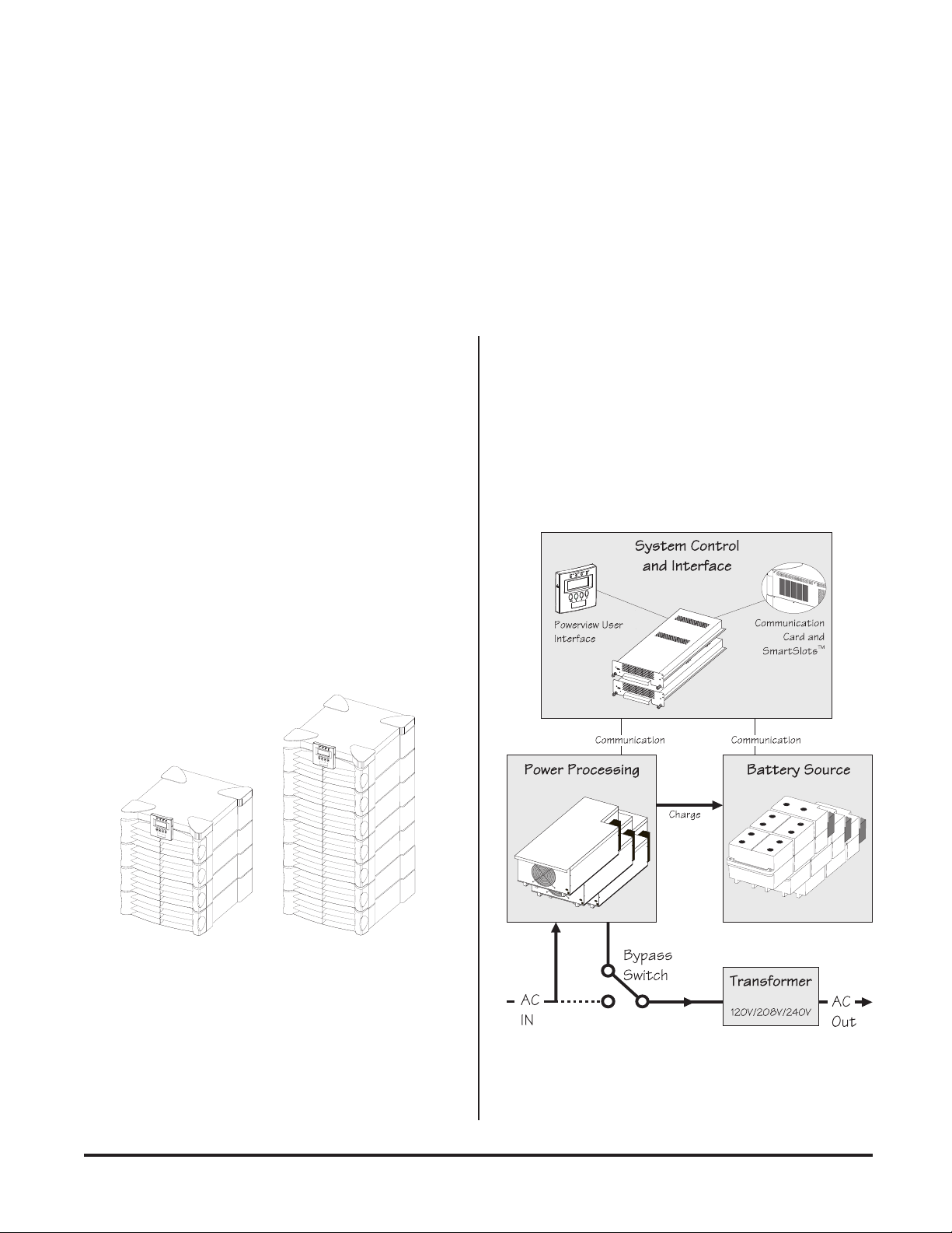
The SymmetraTM Power Array is comprised of three functional components: A power processing system, a battery
source, and a control/user interface system. Output power is
routed through a transformer prior to delivery to the load
equipment. See figure I-2. Each of the functional components
and the transformer are described in the following text.
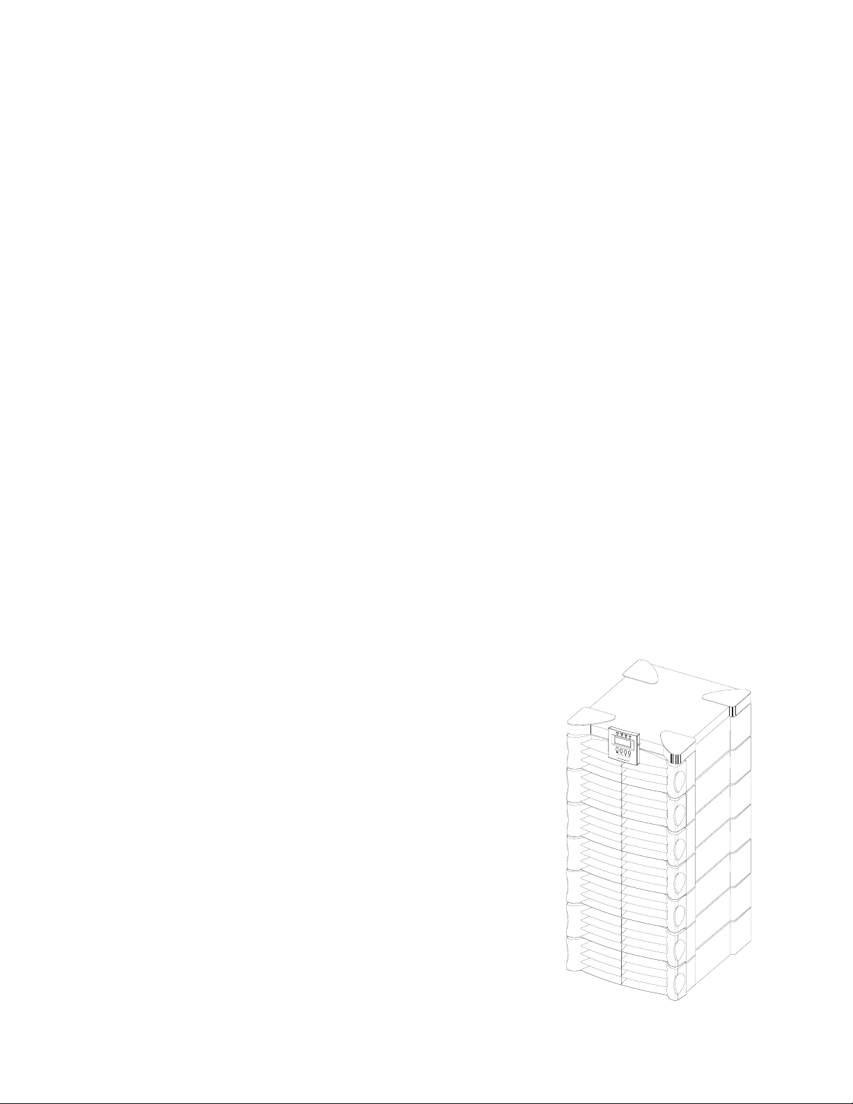
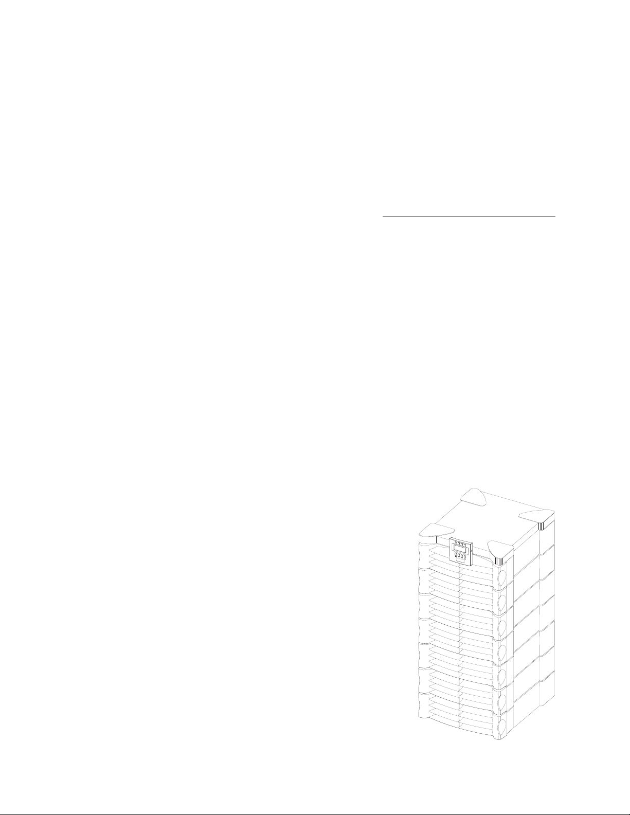
Fig I-1 MiniFrame and MasterFrame
Fig I-2 Functional Diagram of a Symmetra
TM
i
Page 8

Power Processing System
Control/User Interface
The power processing system delivers conditioned AC output
power with a low distortion sinewave. Under normal operating conditions, power is received from the AC utility power
source, conditioned by the power processing system, and delivered to the load equipment. In the event of an AC utility
source failure, the power processing system receives power
from the battery source (battery modules), converts it to conditioned AC, and delivers it to the load equipment. When AC
utility power is present, the power processing system also
maintains the battery source at full charge.
The power processing system in SymmetraTM is comprised of
individual power module(s). Each power module contains
the electronics for a complete 4kVA UPS, including the rectifier,
charger and inverter. When two or more power modules are
present, they operate in parallel, sharing the load equally.
By configuring the system with at least one more power module than is required to power the load (a redundant power
module), SymmetraTM can sustain a power module failure,
and still deliver full power to the load equipment. The failed
module is identified by the control/user interface system, an
alarm is initiated to notify the user of the module failure, and
the hot-swappable module can be replaced by the user, without the need to power down the load equipment.
A SymmetraTM MiniFrame provides bays for up to three power
modules, and a MasterFrame provides bays for up to five.
This provides the full system capacity (8kVA and 16kVA respectively), plus one redundant power module.
Battery Source
The control/user interface system coordinates the operation
of the SymmetraTM and reports status conditions via several
user interface options. Functions performed by the control/
user interface component include module coordination and
state control, analysis and reporting of system status, and
reporting of alarm conditions.
Module Coordination & State Control - The Symmetra
incorporates a main intelligence module (MIM) that continuously monitors the system, and delivers data to both the
PowerView user interface, and to the communication ports.
The MIM coordinates the initial power up of the system, transfers it into and out of bypass mode, transfers the power source
between the utility AC power, and the battery source, and coordinates shutdown operations.
System Status Monitoring - The MIM gathers data about the
system components, and delivers it to both the PowerView
interface, and to the computer interface ports. System status
monitoring and reporting data include the current predicted
run time, the status of individual battery modules and power
modules, input & output voltage, input & output voltage frequency, and the size and status of the current output load.
Alarm Condition Detection - The control/user interface system monitors the SymmetraTM for alarm conditions. If an
alarm condition is detected, the PowerView user interface initiates an audible and visual alarm. Alarm conditions include
on-battery, low battery, module faults, overloads, loss of redundancy and a variety of other default and user defined events.
All possible alarm messages and the appropriate user responses
are provided in chapter 10.
TM
The battery source is comprised of parallel, hot-swappable,
120V battery modules. These are housed in the Symmetra
frame, and in an optional extension battery frame.
A SymmetraTM MiniFrame provides bays for up to two battery modules, and a MasterFrame provides bays for up to
four. Both of these frames can be connected to an extension
battery frame. Additional battery modules increase on-battery run time.
ii
TM
Transformer
The power processing system receives either 208V or 240V
input AC utility power, and delivers 240V power to an internal
transformer. The transformer delivers multiple output voltages (120V/208V/240V) to an output wiring terminal block
inside the SymmetraTM frame. Output wiring procedures are
provided in chapter 4.
Page 9
Modes of Operation
The Power Array functions in one of four modes of operation,
depending on user commands, the status of the AC utility
voltage, and the condition of the SymmetraTM itself. The four
modes are Load-Disconnect, On-Line, On-Battery, and Bypass. The PowerView interface reports the operating mode.
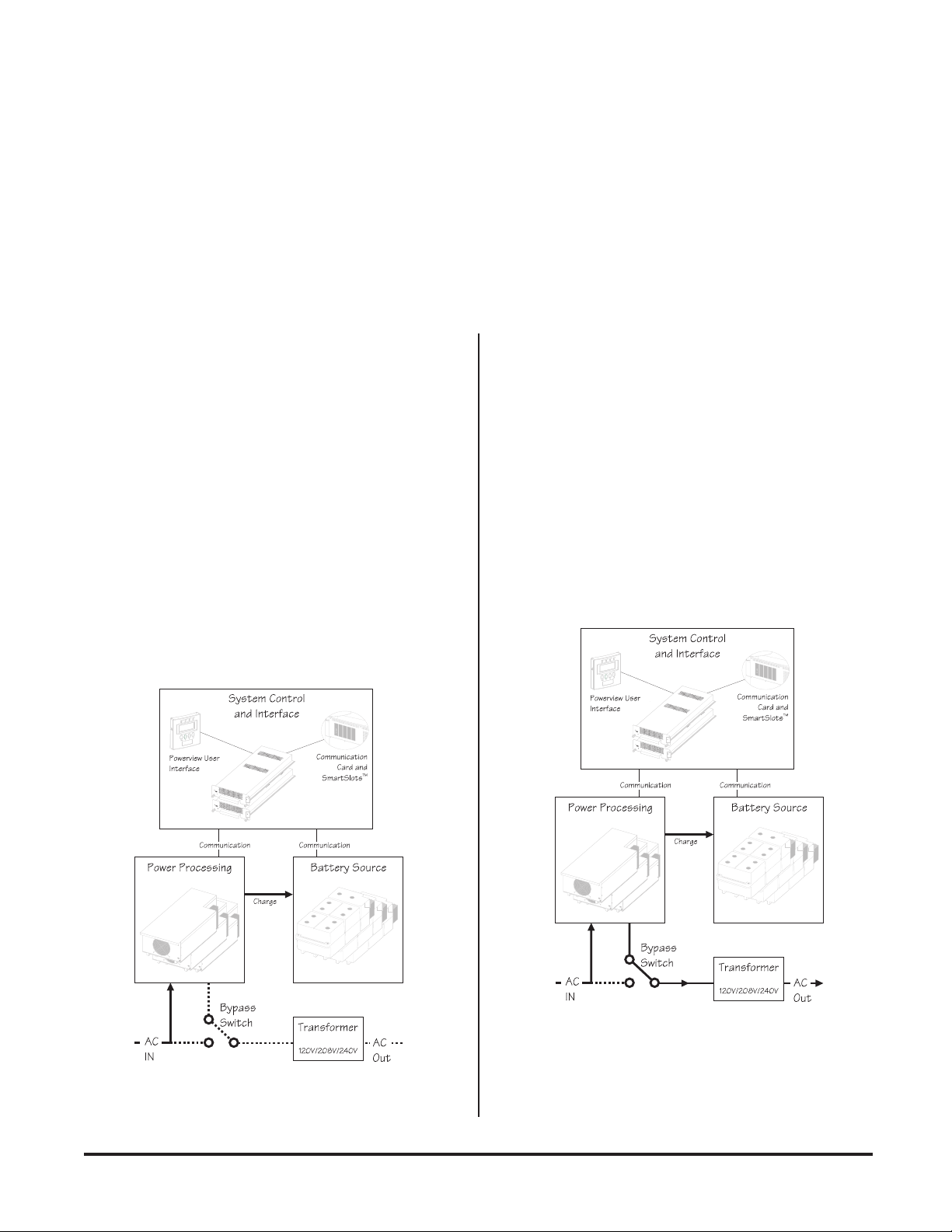
Load-Disconnect Mode
In the load-disconnect mode, incoming AC utility power is
present and the system is internally powered, but no output
power is delivered to the load equipment. The Symmetra
enters the load-disconnect mode at the initial power up, when
the system enable switch is switched to the “on” position. When
the system is operating on-line, and the “load off ” command
is entered in the PowerView interface, it returns to the loaddisconnect mode. Figure I-3 illustrates the power flow when
the system is operating in the load-disconnect mode.
TM
On-Line Operating Mode
The on-line operating mode is the “normal” operating mode.
When the system is in the on-line operating mode, the Power
Array receives power from the AC utility, and delivers conditioned power to the load equipment. The Power Array maintains proper battery charge, regulates the output voltage and
frequency, and protects the load from surges and electrical
noise. SymmetraTM will operate in this mode if it has been
commanded to turn the load on, the incoming utility voltage
is present and functioning properly, and there are no preventing abnormal conditions, such as an overload. See figure I-4
for a diagram of the power flow when the system is in the online operating mode.
Fig I-3 Load-Disconnect Operating Mode
Fig I-4 On-Line Operating Mode
iii
Page 10
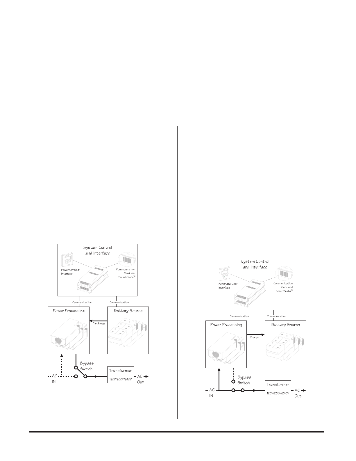
On-Battery Operating Mode
Bypass Operating Mode
When in the on-battery mode, the Power Array draws DC
power from the battery source, converts it to conditioned AC
power that is then delivered to the load equipment.
SymmetraTM typically enters this mode in the event of a utility
power failure. It will also operate in the on-battery mode
during a user initiated battery self test.
On-battery operation is limited in duration and is dependent
upon the number of battery modules, their state of charge,
and the size of the load. SymmetraTM will remain in the onbattery state until either the incoming utility power is restored,
or the batteries are depleted. See figure I-5 for a diagram of the
power flow when the system is in the on-battery mode.
When the SymmetraTM is in the bypass operating mode, the
system is bypassed, and utility power is delivered directly to
the load. SymmetraTM is equipped with an automatic bypass
function to allow the system to automatically go into bypass
mode, and a manual maintenance bypass switch to allow a
user to manually bypass the system. Either can be used to
place the Power Array into bypass operating mode.
The SymmetraTM will automatically transfer to the bypass
operating mode when AC utility power is present, but the load
cannot be powered by the inverter. Events which may cause
this include overloads, or failed non-redundant power modules. The SymmetraTM will automatically return to the on-line
mode when the triggering event clears. Figure I-6 illustrates
the power flow when the system is in the bypass mode.
Fig I-5 On-Battery Operating Mode
Fig I-6 Bypass Operating Mode
iv
Page 11

Definitions
Important Information
The following definitions are used in this manual and will be
helpful in understanding SymmetraTM.
Redundancy - Indicates the presence of one or more extra
modules, allowing the system to sustain a fault and continue
to provide full protection to the load. To be fully redundant,
the system should be configured with a redundant intelligence
module, and at least one redundant power module.
Note: The number of battery modules determines the length of
the run time. While it is prudent to use the maximum number
of battery modules possible, they are not considered redundant.
N+1 Redundancy - Refers to the level of redundancy, specifically related to power modules. “N” represents the number of
modules required to power the load, and “+1, +2, etc.” represents the number of extra power modules that are present.
For example, a 7.3 kVA load requires two power modules for
adequate protection. If the SymmetraTM is configured with
only two modules, it has an “N+0,” level of redundancy. (No
redundancy). If the system is configured with three power
modules, it has an “N+1” redundancy. Depending on the size
of the load, SymmetraTM can be configured with 2, 3 or even 4
extra power modules. Respectively, it would have an N+2,
N+3, or N+4 level of redundancy.
Please read this User's Manual thoroughly, before proceeding
with the installation of the SymmetraTM Power Array system.
It provides important information about installing and using
the SymmetraTM safely and effectively. Pay close attention to
text that is accompanied by a danger, or caution symbol. For
technical support, contact APC at:
1-888-809-TECH
Capacity - The maximum amount of output power that a
SymmetraTM system can deliver. The capacity is limited by the
lesser of the frame size, or the capacity of the installed power
modules.
For example, a MiniFrame (8kVA) with one power module
installed (4kVA) has a system capacity of 4kVA. A MasterFrame
(16kVA) with five power modules (20kVA) has a system capacity of 16kVA.
Hot-swappable - The modules are “hot-swappable” means
they can be replaced safely by a user or service provider while
the load is still powered and fully protected.
v
Page 12
Safety Information
Important Safety Information
Read this safety information in its entirety,
before proceeding with the installation &
operation of the SymmetraTM Power Array.
Page 13

Safety
Symbols Used In This Manual
The following symbols appear in this User's Manual:
CAUTION/DANGER - Caution indicates risk of
bodily harm. Danger indicates that a risk of electrical shock is present and the associated procedures should be followed carefully.
“STAND BY MODE” - The system enable switch,
and the input circuit breaker use the “stand by”
mode. When either of these are switched to “stand
by,” the Power Array is disconnected from utility
input voltage. In this mode, the system appears to
be off, although the utility power is still connected
to the system. For this reason, the standby mode
is unsafe for servicing the system. Always follow the
five step Total Power Off procedure before servicing the Power Array. (See procedure at right.)
“OFF POSITION” - The maintenance bypass
switch is the only switch that can be placed in the
“off” position. When switched to the “off” position, the Power Array functions normally, receiving power from the utility source, and delivering
conditioned power to the load equipment.
“ON POSITION” - All three switches (The system enable switch, the maintenance bypass switch
and the input circuit breaker) can be placed in the
“on” position. See the description for each of these
switches in chapter 1.
SAFETY EARTH GROUND - Indicates the primary safety ground.
IMPORTANT SAFETY INSTRUCTIONS
n SAVE THESE INSTRUCTIONS - This manual contains
important instructions that should be followed during
installation and maintenance of the Power Array, and for
installation or replacement of the battery and power modules.
CONSERVER CES INSTRUCTIONS. CETTE NOTICE
CONTIENT DES INSTUCTIONS IMPORTANTES
CONCERNANT LA SÉCURITÉ.
n Connection to the branch circuit (mains) must be per-
formed by a licensed electician.
n Installation of the power and battery modules can be per-
formed by any individual with no previous technical experience.
n Operation of the equipment can be performed by any
individual with no previous technical experience.
n The protective earth conductor for the SymmetraTM car-
ries the leakage current from the load devices (computer
equipment). Therefore, the size of the conductor must be
at least as large as the wire required by IEC 950. IEC 950
states the following nominal cross-sectional areas:
- 2.5 mm2 for rated current between 17 & 25 A
- 6 mm2 for rated current between 33 & 40 A
- 10 mm2 for rated current between 41 & 63 A
- 16 mm2 for rated current between 64 & 80 A
n FIVE STEP TOTAL POWER OFF PROCEDURE
To remove all power from the Power Array (Total Power
Off), the following series of events must occur in the order listed:
1. Set system enable switch to the “stand by” position.
2. Set input circuit breaker to the “stand by” position.
3. Remove all battery modules from the Power Array.
4. Disconnect external battery cabinet (if present).
5. Disconnect the mains/branch circuit breaker.
Safety-1
Page 14

Safety
n CAUTION: Risk of Electrical Shock and Energy Hazard,
120V, 7.2 Ah battery module. Before replacing battery
modules, remove conductive jewelry such as chains, wrist
watches and rings. High short circuit current through
conductive materials could cause severe burns.
n CAUTION: Do not dispose of batteries or battery mod-
ules in a fire. The batteries may explode.
n CAUTION: Do not open or mutilate battery modules or
batteries. Released electrolyte is harmful to the skin and
eyes. It may be toxic.
n While battery modules are user replaceable, servicing of
the battery modules themselves should be performed or
supervised by personnel knowledgeable of batteries and
the required precautions. Keep unauthorized personnel
away from batteries.
n When replacing or adding battery modules to the Power
Array system, use only the “SYBATT SymmetraTM Battery Module.” Contact APC for technical support, for
additional, or for replacement battery modules at:
1-888-809-TECH
Safety-2
Page 15

Chapter One
Physical Representation
This chapter provides an illustrated descrip-
tion of the SymmetraTM Power Array sys-
tem, and each of the modular components.
Before proceeding, examine the illustration
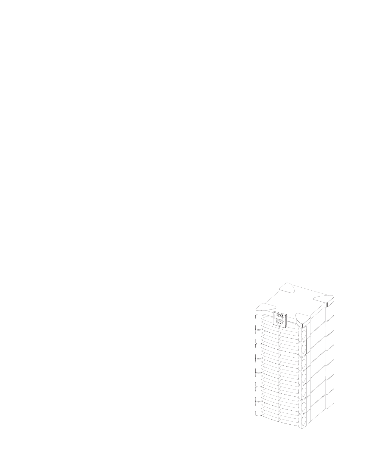
below. It depicts a MasterFrame (16kVA)
Power Array as it appears during normal
operating conditions. The grill covers are
correctly installed, and the Powerview
Interface is mounted on the frame.
Page 16
Chapter 1 - Physical Representation
The Power Array Frame
The SymmetraTM Power Array frame serves as the base for the
modular components of the system. The MiniFrame provides bays for three power modules, and two battery modules. The MasterFrame provides bays for five power modules, and four battery modules. Both frames provide one bay
at the top right that houses the main intelligence module (MIM)
and redundant intelligence module (RIM).
The bottom of both frames contain wiring input/output access panels and terminal blocks. A system enable switch, input
circuit breaker and maintenance bypass switch are also located at the bottom of the frame. The output voltage transformer is located inside the bottom of the frame. A fully loaded
MiniFrame is depicted in figure 1-1. A MasterFrame with
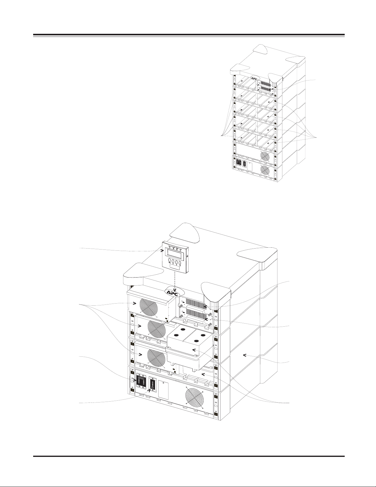
factory installed MIM and RIM, and empty power and battery module bays is depicted in figure 1-2.
Five
Power
Module
Bays
Fig 1-2 An Empty MasterFrame (grill covers removed)
Main
Intelligence
and
Redundant
Intelligence
Modules
Four
Battery
Module
Bays
Powerview
Interface
Power
Modules
Input
Circuit
Breaker
Maintenance
Bypass
Switch
Redundant
Intelligence
Module
Main
Intelligence
Module
MiniFrame
Battery
Modules
Fig 1-1 A Fully Loaded MiniFrame (grill covers removed)
1-1
Page 17
Chapter 1 - Physical Representation
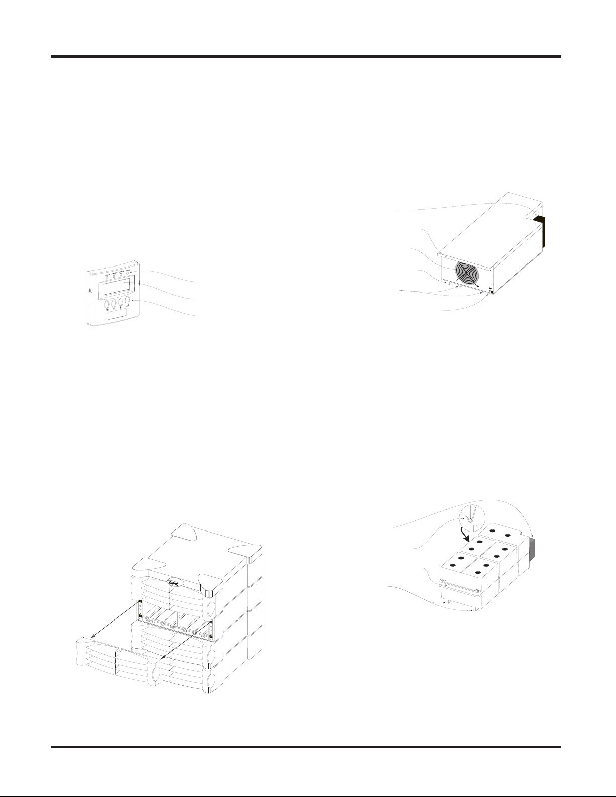
Powerview User Interface
The Powerview incorporates a 4 x 20 alphanumeric LCD screen
with four navigation keys, four LED status indicators, and an
audible alarm beeper. The display communicates with the
Power Array via a local RJ45 connector cable that is hardwired
into the top power module bay. It can be mounted on the
front of the frame, stand on top of the frame, or it can be
installed at a remote location. (A 20’ RJ45 cable is provided,
and plugs into a communication port at the rear of the frame.)
The alphanumeric LCD screen displays system status, fault
reporting and module diagnostics information. The navigation keys are used to scroll through an elaborate menu. Chapter 6 provides detailed information about the Powerview.
LED Status Indicators
LCD Screen
Navigation Keys
Fig 1-3 Powerview User Interface
Alarm thresholds and parameters are set with the Powerview.
In the event of an alarm condition, the Powerview emits both
audible and visual alarm indicators.
Power Module
The power module is a self-contained, 4kVA UPS (without
batteries) housed inside a metal enclosure. A blind mating
connector at the rear of the module engages with a connector
inside the frame, and powers the unit. Power modules are
installed in the vertical column of bays at the left of the frame.
These bays are labelled L1, L2, L3, etc.
Blind Mating
Connector
Positioning Handle
Cooling Fan Grill
Alignment Runner
Seating Tabs
Flip Latch Micro Switch
Fig 1-4 Power Module
In the event of a power module failure, the Powerview initiates
an audible alarm, and displays an error message. The power
module is hot-swappable. Instructions for module replacement are provided in chapter 8.
Louvered Grill Covers
Each level of the frame is equipped with a louvered grill cover.
These covers are interchangable, and snap securely onto the
frame. When removing, temporarily storing, and replacing
grill covers, use care to prevent them from being marred or
scratched.
Fig 1-3 Front Grill Cover Removal and Replacement
Battery Module
The battery module is comprised of a series of ten 12V batteries housed inside a plastic enclosure. A blind mating connector at the rear of the module engages with a connector inside
the frame.
Blind Mating
Connector
Retaining Flange
Positioning Handle
Runners
Fig 1-5 Battery Module
Battery modules are installed in the vertical column of bays at
the right of the frame. These are labelled R2, R3, R4, etc. (The
top right bay houses the intelligence modules.) The condition
and charge of each battery module is reported on the
PowerView. If a battery module fails, an alarm is initiated.
Battery modules are hot-swappable, and user replaceable.
1-2
Page 18
Chapter 1 - Physical Representation
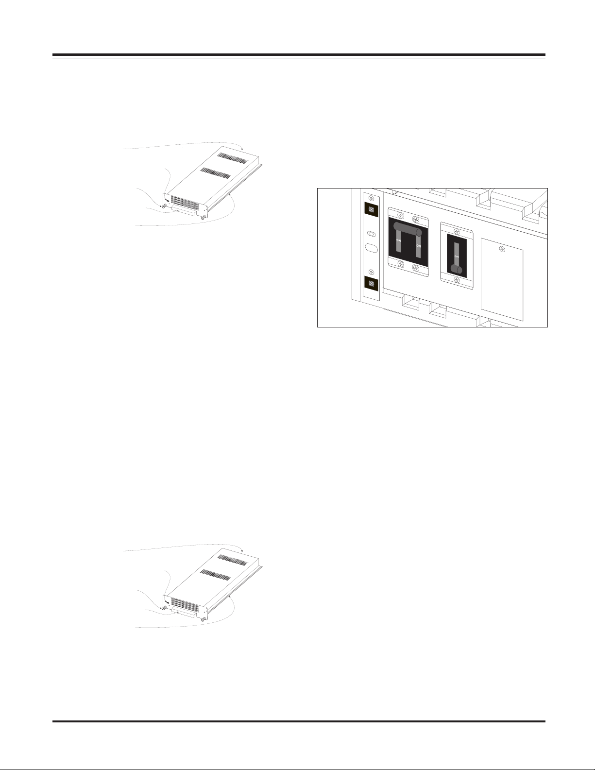
Main Intelligence Module (MIM)
The MIM is the onboard computer for the Power Array system. It gathers and processes data, including monitoring the
condition of each of the modules.
Blind Mating
Connector
Flip Latch Micro Switch
Retaining Screw
Positioning Handle
Installation Rail
Fig 1-6 Main Intelligence Module
The PowerView functions as the user interface for the MIM,
and is used to access data, and to configure the system. When
a redundant intelligence module is installed and functioning,
the main intelligence module can be replaced without placing
the load at risk. The main intelligence module also communicates to an external battery frame (if present). The main intelligence module and the redundant intelligence module are factory installed into custom racks that are built into the bay at
the upper right of the frame.
Important: The MIM is always installed in the bottom rack, and
the RIM is always installed in the top rack.
Redundant Intelligence Module
(RIM)
The redundant intelligence module is a back-up version of the
main intelligence module. It provides redundancy in the event
of a MIM failure, or while a MIM is being replaced. If a functioning MIM is present, the RIM can be removed and replaced
without placing the load at risk. The condition of the RIM can
be determined with the PowerView.
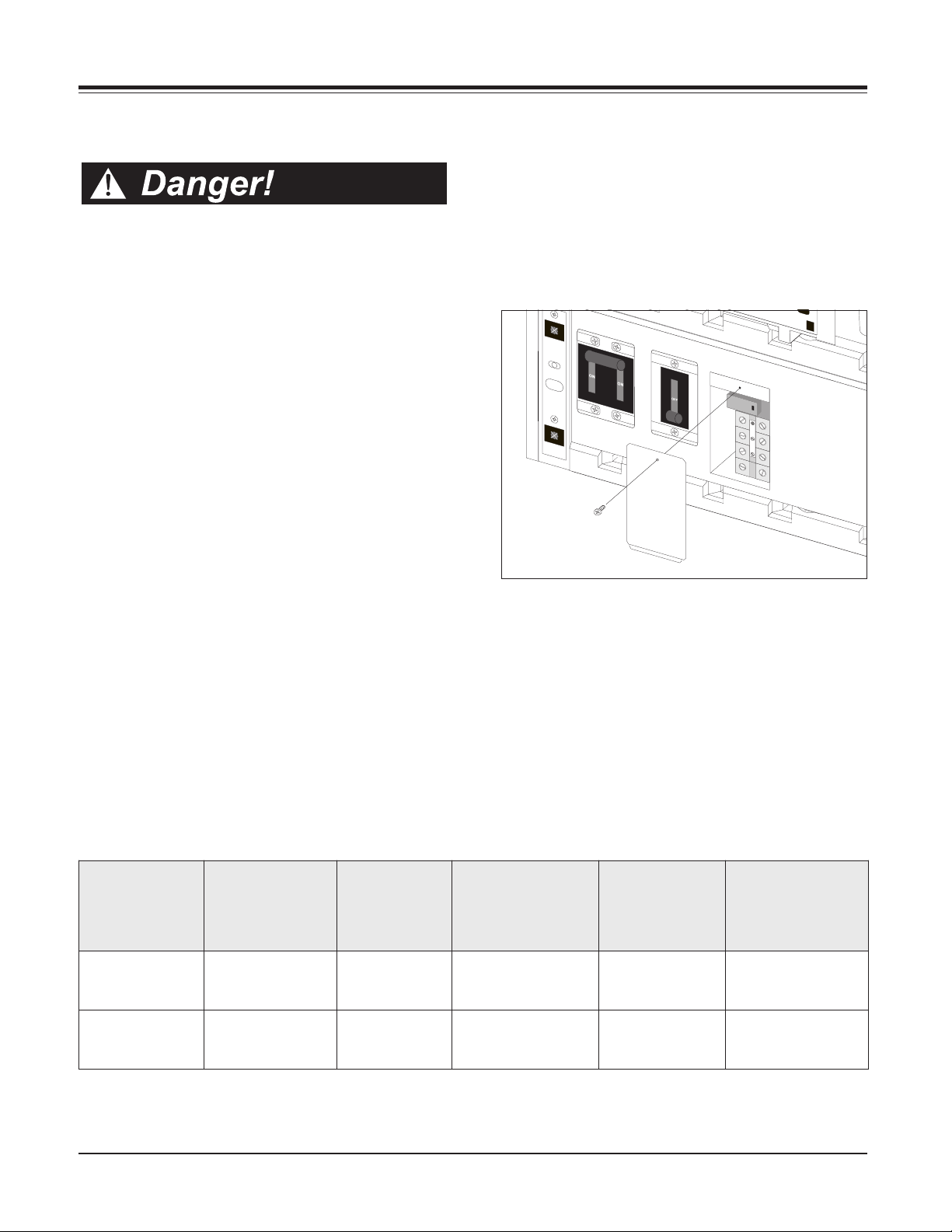
Input Circuit Breaker
The input circuit breaker protects the Power Array from extreme overloads. When switched to “stand by” the Power
Array is disconnected from incoming utility voltage. When
switched to the “on” position, power flows from the utility
source into the Power Array. Under normal operating conditions, the input circuit breaker always remains in the “on” position.
Fig 1-8 Input Circuit Breaker & Maintenance Bypass Switch
Maintenance Bypass Switch
When switched to the “on” position, the maintenance bypass
switch bypasses the Power Array, and causes the load equipment to be powered directly from utility power. When it is
switched to the “off ” position, utility power flows into the
Power Array, and conditioned power is delivered to the load
equipment. The load equipment is unprotected when the main-
tenance bypass switch is in the “on” position. Under normal
operating conditions, the maintenace bypass switch always
remains in the “off” position.
Blind Mating
Connector
Flip Latch Micro Switch
Retaining Screw
Positioning Handle
Installation Rail
Fig 1-7 Redundant Intelligence Module
1-3
Page 19

Chapter 1 - Physical Representation
Rear View of a Power Array
The rear of a MiniFrame system is displayed below. The rear
of a MasterFrame is similar. Each of the components are
described in a section that follows:
System Enable Switch
The system enable switch regulates internal power to the Power
Array. It does not power the load. When switched to the “on”
position, the Power Array enters the load-disconnect operating mode. When switched to “stand by” the Power Array is
disconnected from incoming utility voltage. The load is not
powered until the “power the load” command is entered into
the PowerView interface.
Communication Interface Ports
The following three communication ports are provided: A
remote PowerView cable port; an APC PowerChute Plus software interface port, and two battery extension frame communication ports. A 20’ RJ45 cable is provided with the Power
Array for remote installation of the PowerView.
TM
Smart Slots
APC manufactures a set of auxillary user interface accessories,
called SmartSlot
are provided. SmartSlotTM interface options include:
Accessory Ports
TM
devices. Four SmartSlotTM installation ports
n Protection and safe shutdown of multiple servers
n SNMP adaptor for accessing data via a network
n CallUPSTM - Initiates telephone notification of power event
n MeasureUPSTM - monitoring environmental conditions
n Control and monitor via modem
Note: Use only SmartSlot
TM
devices labelled “Symmetra
TM
compatible.”
REPO/Input/Output Wiring Access Panels
Wiring terminal blocks for input and output wiring, and for
remote emergency power off (REPO) switch intallations are
accessed through these panels. For use by a licensed electrian.
Power Distribution Unit Panel (Optional)
An optional power distribution unit provides output power
receptacles and corresponding circuit breakers. The MiniFrame
PDU provides one L6-30R receptacle (208V), two 5-15R receptacles (120V), and two L14-30R receptacles (120V/240V). The
MasterFrame PDU provides three L6-30R receptacles, four 515R receptacles, and three L14-30R receptacles. The PDU panel
for both frame sizes are equipped with a panel circuit breaker.
Battery Extension Frame Connector
An optional Battery Extension Frame can be connected to the
Power Array using this coupler. See the User’s Manual inluded
with the Battery Extension Frame.
Communication
Interface
Ports
Power Distribution
Unit (Optional)
System
Enable
Switch
Battery
Extension
Frame
Connector
REPO Wiring
Access Panels
SmartSlot
Accessory
Ports
MiniFrame
Output
Wiring
Access
Panels
Input
Wiring
Access
Panels
TM
1-4
Fig 1-8 Rear View of a Mini Frame SymmetraTM Power Array System
Page 20

Chapter Two
Site Preparation
This chapter provides the site requirements
for a SymmetraTM Power Array system.
Included are structural and environmental
requirements, weights, dimensions and the
heat output of a functioning system.
Page 21
Chapter 2 - Site Preparation
Space and Weight Considerations
All Power Array frames are 24” wide and 27” deep. Refer to
table 4-1 for dimensions and weights of fully loaded systems.
Table 2-1 Power Array Dimensions and Weights (Fully
Loaded with Modules)
Make sure there is adequate space and structural integrity to
support the fully loaded frame. Refer to figure 2-1 below. The
weight of the Power Array rests on four 1.5” diameter leveling
feet. Positions of the leveling feet are shown. When installing
the frame, allow 12” of clearance behind the frame for adequate airflow. (The fans on the system pull air in through the
front of the frame, and blows it out the back.) Allow 48” of
clearance in the front of the SymmetraTM to access the
PowerView interface, and for installation and replacement of
modules.
Rear
Clearance
Operating Conditions
The Power Array is intended for installation in a temperaturecontrolled, indoor area, free of conductive contaminants. The
operating evironment must be clean, dry and protected. The
atmosphere must be free of dust and corrosive fumes. Adequate airflow must be provided for the operation of the system. Make sure environmental conditions where the
SymmetraTM is to be installed are within the following parameters:
n Operating Relative Humidity: The Power Array will op-
erate within a relative humidity range of 0 to 95%, noncondensing.
n Operating Temperature: The Power Array will operate
within a temperature range of 32°F to 104°F (0°C to 40°C).
n Operating Elevation: The Power Array will operate at
elevations within a range of 0ft to 10,000ft (0m to 3,048m).
n Electro-Static Discharge (ESD) Susceptibility: The Power
Array and all modules are capable of withstanding
“through air” electro-static discharges up to an amplitude of +/-15kV and “direct discharge” electro-static discharges up to an amplitude of +/-8kV without failure,
abnormal operation or degradation in performance. ESD
test methods conform to IEC 801-2.
BTU Output
Footprint and
Feet Positions
Front Clearance
Fig 2-1 System Footprint and Required Clearance
Transporting Power Array to Installation Site
When it is shipped, the Power Array frame is bolted to a custom-designed pallet. The modules are stacked on either one
or two additional pallets. It is recommended that these pallets
be moved from the receiving dock to the installation area with
a pallet jack. Make sure there is enough space and structural
integrity to move these pallets.
Refer to table 2-2 for BTU output of a fully loaded, and functioning Power Array system. The BTU output is significantly
higher while the batteries are charging. Under normal operating conditions, battery recharge periods are relatively infrequent.
Table 2-2 BTU Output
Temporary Storage of Modules
The battery and power modules must be temporarily stored
until the frame is permanently installed. To preserve battery
life, always store batteries in a cool, dry place.
2-1
Page 22

Chapter 2 - Site Preparation
2-2
Page 23
Chapter Three
Unpacking and Installing Frame
Because the installation process begins on
the loading dock, this chapter provides the
procedures for inspecting the Symmetra
Power Array frame and modular components
when they arrive. It includes procedures for
moving the frame to the installation site,
removing it from the pallet, and preparing the
frame and the modules for installation.
TM
Page 24

Chapter 3 - Unpacking and Installing Frame
Initial Inspection
The SymmetraTM Power Array system is shipped on pallets.
The system frame is bolted to one pallet, and the modules are
boxed, and stacked on one or two additional pallets.
Check For Damage
1. Inspect the Packaging - for damage or signs of mishandling before moving the pallets. If damage is detected, note it
on the Bill of Lading.
2. If Any Damage Is Detected - file a damage claim with the
shipping agency within 24 hours. Contact APC Customer
Service at 1-800-800-APCC to inform them of the damage
claim, and the condition of the equipment.
3. System Administrator- make sure the system administrator participates in the initial inspection.
Tools Required for Setup
The following tools are required to move the pallets into place,
remove packaging materials, install the ramp on the frame
pallet, and to remove the frame from the pallet.
1. Large Philips screwdriver
2. Adjustable, open-end wrench
3. Heavy duty shears
4. Sharp utility knife
5. Pallet jack
Storage of Battery and Power
Modules
The modules must be temporarily set aside, while the frame is
installed and wired. To preserve battery life, always store battery modules in a cool, dry place.
Moving the Frame
1. Plan the Route - Make sure all passages are large enough to
accomodate the frame, and the pallet jack. Check to see that
the floor has sufficient strength. See Table 3-1 for weights and
dimensions. Check doorways, elevators, ramps, etc, to insure
there are no non-negotiable corners, step-ups, or offsets. Select a route that provides the smoothest possible floor surface.
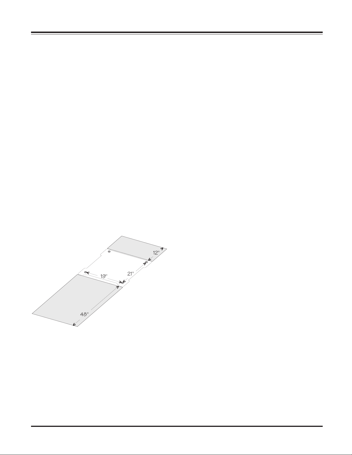
2. Staging Area - A smooth, level floor surface is required to
position the frame pallet, remove the packaging materials, install the ramp, and for two people to carefully roll the frame
down the ramp, and onto the floor. See Figure 3-1 below for
staging area dimensions.
Table 3-1 Dimensions and Weights
Handling Considerations
1. The Frame Pallet - See Table 3-1 for frame pallet weight and
dimensions. Before removing shipping materials, the frame
and pallet should be positioned as close as possible to the
installation site. The frame is bolted to a specially designed
pallet, and is removed from the pallet using a ramp that is
included. Use a pallet jack to position the frame pallet.
Note: Do not attempt to move the frame with a hand dolley.
2. The Modules Pallet - If possible, it is recommended that the
module pallet(s) be positioned as close as possible to the final
installation site with the pallet jack. If this is not possible,
remove the outer packaging materials from the module cartons, and carry each individual, boxed module to the installation site. See Table 3-1 for module weights.
Fig 3-1 Staging Area
3. Using a Pallet Jack - Carefully move the frame to the staging area.
3-1
Page 25

Chapter 3 - Unpacking and Installing Frame
Remove Packing Materials
Note: It is recommended that all packaging materials be removed, and temporarily stored, in case any of the system components must be returned to the factory.
1. Remove the Shipping Bands - Using appropriate precautions, carefully cut the plastic shipping bands.
2. Removing the Plastic Wrap - Using care to not damage the
surface of the Power Array, cut off the plastic wrap by running
the tip of a sharp utility knife along the surface of one of the
cardboard corner supports. Remove the plastic wrap from
the frame.
3. The Pallet Ramp - The pallet ramp is shipped under the
cardboard cap, on top of the frame. It will sometimes become
wedged inside the cardboard cap. Use caution removing this
cap from the frame. Remove the ramp from the top of the
frame.
4. Corner Supports - When the cardboard cap is removed,
the four corner supports will fall away. Remove them, and
place to one side.
5. Remove the Cover Grills - Remove the grill covers from the
frame. Grasp each grill cover by the side finger hold that is
molded into them. Pull straight forward. Set the covers to one
side. Be careful not to scratch them.
6. Leveling Feet - Fully retract each of the four leveling feet
located near the casters on the bottom of the frame.
3. Install the Ramp - Position the ramp so that the installation
bolts line up with the ramp bolt holes on the pallet. Install the
ramp onto the pallet as shown in Figure 3-3.
Fig 3-3 Frame Pallet Ramp
4. Roll the Frame from the Pallet - The following operation
requires two people. Holding the frame near the center, care-
fully roll it down the ramp, and onto the floor. (The frame is
equipped with casters.)
5. Roll the Frame to the Installation Site - Carefully roll the
frame from the staging area to the final installation site.
6. Shipping Material Storage - Gather all shipping materials
together, and store it temporarily, in case any system component must be returned to the factory.
Fig 3-2 Frame Restraint and Ramp Holes
Remove the Frame from the Pallet
1. Loosen Rear Bracket Screws - Loosen the two phillipshead screws securing the brackets at the rear of the frame.
2. Remove Two Pallet Restraint Screws - See Figure 3-2. Remove the two phillips-head, pallet restraint screws. Use the
cloth handle to remove the frame restraint from the pallet.
Place the frame restraint and two screws to one side.
Moving Battery & Power Modules
1. Moving All Modules On Pallet - Using the pallet jack, move
the modules pallet(s) to the installation site. If necessary, the
modules can be moved one at a time. Remove all outer packaging materials from pallet, and carry each boxed module to
the final installation site.
3. Stack Modules - Carefully stack the battery and power
modules near the installation site. Leave enough room for the
electrican to install the wiring to the frame.
Clean-UP
1. Packaging Materials - Remove all packaging materials from
the installation site. Store it temporarily, so that it will be
available if any components must be returned to the factory.
2. Final Inspection - Check the module bays of the frame to
make sure they are clear of debris.
3-2
Page 26

Chapter Four
Wiring Requirements & Procedures
This chapter is addressed to the licensed
electrican who will install the input, output
and remote emergency power off hardwiring
connections. Circuit requirements and
minimum wire gauges are included.
Page 27

Chapter 4 - Electrical Requirements and Procedures
SymmetraTM Wiring
n All power and control wiring must be installed by a
licensed electrician only. All input, output and emergency power off wiring must comply with the National
Electric Code (NEC) and applicable local codes.
n It is highly recommended that flexible metal conduit
be used when hardwiring the Power Array. This will
provide for ease of service and maintenance of the system.
There are four categories of hardwiring installation procedures for the SymmetraTM Power Array. These are; input
wiring, output wiring, remote emergency power off switch
wiring, and installing an optional local grounding electrode.
Input Wiring
The Power Array requires a single phase 208V or 240V incoming AC utility power source. Incoming power is wired
directly to a terminal block inside the Power Array. Specifications and installation procedures are provided.
REPO Switch Wiring
The SymmetraTM Power Array can be connected to either a
dry contact, or a 24Vdc remote emergency power off (REPO)
switch. The wiring terminal connections for the REPO are
physically isolated from the primary circuitry of the Power
Array. Specifications and installation procedures for REPO
wiring are provided.
Local Grounding Electrode
A 1/2” knockout is provided on the output wiring access panel
for those sites where NEC code 250-26 requires a local
grounding electrode. This grounding electrode is installed in
addition to the equipment safety ground that is run with the
input hardwiring connection. The local grounding electrode
is connected from the output terminal block to the nearest
effective ground, such as building steel, a metal water pipe,
or other appropriate grounding structure. The procedure
for installing a local grounding electrode is included in the
output wiring procedures.
Note: The local grounding electrode must meet National Electric Code standards, as per NEC Table 310-16.
Output Wiring
Power is distributed to the load equipment via hardwired
connections to an output terminal block inside the frame,
and by plugging the load equipment into an optional power
distribution panel. The Power Array delivers 120V/208V/
240V power to the output terminal block. Configurations
for hardwiring 120/240V and 120/208/240V output voltages
are provied in this chapter. Specifications and installation
procedures are provided.
4-1
Page 28
Chapter 4 - Electrical Requirements and Procedures
Input Wiring
n Verify that all incoming line voltage (utility power)
and low voltage (control) circuits are de-energized, and
locked out before installing cables or making connections, whether in the junction box or to the
SymmetraTM Power Array.
n Always verify that all battery modules are removed
and all battery extension frames are disconnected from
the Power Array before installing any wiring to the
Power Array.
n Read this chapter completely before installing any wir-
ing to the Power Array.
Input Wiring Specifications
The Power Array requires either a single phase 208V, 50/60Hz,
or a 240V, 50/60Hz incoming utility power source. A 3-conductor cable (2 live, 1 ground) is to be brought to the input
wiring terminal block inside an adequate length of flexible
metal conduit. To minimize disturbances caused by other
loads in the building, input wiring should be supplied directly from the service entrance (a dedicated power feeder).
All electrical service, both input and output, must be sized in
accordance with the NEC and any local building codes. The
circuit for input power must be adequate to carry the full
load of the system and the load equipment. The 3-conductor input cable should be sized for no more than 3% voltage
drop. A 3/4” knockout in the input wiring access panel provides access to the terminal block.
See table 4-1 for input wiring specifications.
Input Wiring Procedures
An input voltage jumper must be manually set before input
wiring can be installed. Follow the procedure below:
Voltage Jumper Procedure
1. Refer to figure 4-1. Remove the screw that secures the
voltage select access panel to the frame. Place the screw and
access panel aside temporarily.
Fig 4-1 Voltage Select Access Panel
2. Use a small, flat head screwdriver to position the input
voltage jumper to the correct voltage setting. See figure 4-2.
Do not overtighten screws.
Note: When the input voltage jumper is in the 240V position,
the jumper bar activates a micro switch at the top of the terminal block. In the 208V position, the micro switch is not activated.
4-2
tupnI
egatloV
sulperiw-2(
)dnuorg
caV802
caV042
emarF
eziS
AVk.xaM(
)gnitaR
)AVk8(iniM
)AVk61(retsaM
)AVk8(iniM
)AVk61(retsaM
Table 4-1 Input Wiring Specifications
lluFtupnI
daoL
egarepmA
pmA04
pmA08
pmA53
pmA07
tupnI
tnerrucrevO
noitcetorP
)lanretxE(
pmA05
pmA001
pmA05
pmA001
muminiM
eriWtupnI
eguaG
eguaG8#
eguaG3#
eguaG8#
eguaG3#
muminiM
eriWdnuorG
eguaG
eguaG8#
eguaG3#
eguaG8#
eguaG3#
Page 29

3. After the electrical wiring test/checklist is completed (end
of this chapter), replace the voltage select access panel.
240V
208V
Chapter 4 - Electrical Requirements and Procedures
Fig 4-4 Input Wiring Pathway
Fig 4-2 Input Voltage Jumper
Input Wiring Procedure
1. Refer to figure 4-3. Locate the input wiring entry and
input wiring inspection panels.
2. Remove the four screws securing the panels to the frame.
Remove only the screws indicated in the illustration. Place
the screws and panels to one side.
Fig 4-3 Removal of Input Hardwiring Panels
2. Pull the three input wires through conduit, leaving about
20” of wiring extending from the end. Install a flexible metal
conduit connector to the end of the conduit. Using appropriate tools, remove the knockout in the entry panel. Feed
the wires through the entry panel, and attach the flexible metal
conduit connector to the panel. Strip 1/2” of insulation from
the end of each of the incoming wires.
3. Feed wire into the entry compartment through the wiring
pathway hole between the input wiring entry compartment
and the input wiring compartment. See figure 4-4 for the
input wiring pathway.
4. Connect input wires to the input terminal block connections labelled L1, L2/N and Ground as shown in figure 4-5.
Make sure there are no loose strands and that the terminal
connection screws are sufficiently tightened. Connections
are the same for 208V or 240V incoming voltages.
Note: In North America, L2/N is a phase (hot) connection. In
Europe, L2/N indicates a neutral connector.
Fig 4-5 Input Hardwiring Configuration
5. Carefully fold the excess wiring into the entry compartment. After the electrical wiring test/checklist is completed
(end of this chapter), replace the input wiring panels.
4-3
Page 30

Chapter 4 - Electrical Requirements and Procedures
Output Wiring
Output voltage is delivered to the load equipment via
hardwired connections and/or via receptacles on an optional
power distribution unit (PDU). To facilitate maintenance
and service of the Power Array, it is recomended that flexible
metal conduit be used for all hardwiring connections.
See table 4-2 for output wiring specifications.
Output Wiring Configurations
The Power Array is typically wired to deliver either120V/240V,
or 120V/208V/240V output voltages. The internal wiring to
the output terminal block is depicted in figure 4-6. Note the
neutral ground bond in figure 4-7. Wiring configurations
for installations with a power panel are provided in figures
4-8 and 4-9. If wiring is to be connected directly to the load
equipment, refer to table 4-3 for the correct terminal connections.
Note: Use only the connections shown in table 4-3. All others
will yield voltages other than normal utility voltages.
egatloV *snoitcennoC
V021 8-6ro8-2
V042 6-2
V802 6-4
rehtollA.snoitcennocesehtylnoesU*
nahtrehtosegatlovdleiylliwsnoitanibmoc
.segatlovytilitulamron
Table 4-3 Terminal Block Voltage Combinations
Fig 4-6 Voltages Delivered to the Output Terminal Block
Neutral
Ground
Bond
.
Fig 4-7 Output Wiring Neutral Ground Bond
Output Overcurrent Protection
SymmetraTM requires output voltage overcurrent protection
in accordance with the ratings in table 4-2. If an optional
PDU is installed on the Power Array, the panel circuit breaker
acts as the overcurrent protection for the PDU receptacles
and the hardwired connections. See figure 4-11 and 4-12. If a
PDU panel is not installed, circuit breakers must be installed
in the power panels as shown in figures 4-8 and 4-9.
4-4
tuptuO
egatloV
caV042/021
)dnuorg+seriw-2(
caV042/802/021
)dnuorg+seriw-3(
emarF
eziS
AVk.xaM(
)gnitaR
)AVk8(iniM
)AVk61(retsaM
)AVk8(iniM
)AVk61(retsaM
Table 4-2 Output Wiring Specifications
mumixaM
rePtuptuO
rotcudnoC
pmA04
pmA08
pmA04
pmA08
tuptuO
tnerrucrevO
noitcetorP
)lanretxE(
)elop-2(pmA05
)elop-2(pmA09
)elop-3(pmA05
)elop-3(pmA09
muminiM
tuptuO
eriW
eguaG
eguaG8#
eguaG3#
eguaG8#
eguaG3#
muminiM
dnuorG
eriW
eguaG
eguaG8#
eguaG3#
eguaG8#
eguaG3#
Page 31

Chapter 4 - Electrical Requirements and Procedures
Fig 4-8 Output Wiring Configuration for 120V/240V Output Voltages
Fig 4-9 Output Wiring Configuration for 120V/208V/240V Output Voltages
4-5
Page 32

Chapter 4 - Electrical Requirements and Procedures
Output Wiring Installation
n Verify that all incoming line voltage (utility power)
and low voltage (control) circuits are de-energized, and
locked out before installing cables or making connections, whether in the junction box or to the
SymmetraTM Power Array.
n Always verify that all battery modules are removed
and all battery extension frames are disconnected from
the Power Array before installing any wiring to the
Power Array.
n Read this chapter completely before installing any wir-
ing to the Power Array.
Output Wiring Procedure
1. Refer to Fig 4-10. Remove the four screws holding the
output wiring entry panels to the rear of the Power Array.
Remove only the screws indicated in the illustration. Set the
screws and both panels aside temporarily.
output wiring to the output terminal connections. Make sure
there are no loose strands and that the terminal connection
screws are sufficiently tightened.
Grounding Electrode (Optional)
If installing an optional grounding electrode, use the 1/2”
knockout in the output wiring panel, and attach the grounding electrode to the output terminal block ground connection. (Use a strain relief clamp, or a flexible metal conduit
connector.) Connect the local grounding electrode to the
nearest effective ground, such as building steel, a metal water
pipe, or other appropriate grounding structure.
See NEC code 250-26 and Table 310-16.
4. Carefully fold excess output wiring into the terminal compartment. After the electrical wiring test/checklist is completed (end of this chapter), replace the output wiring access
panels.
Power Distribution Units (Optional)
An optional power distribution unit provides output power
receptacles and corresponding circuit breakers. The
MiniFrame PDU provides one L6-30R receptacle (208V), two
5-15R receptacles (120V), and two L14-30R receptacles
(120V/240V). The MasterFrame PDU provides three L6-30R
receptacles, four 5-15R receptacles, and three L14-30R receptacles. The PDU panel for both frame sizes are equipped
with a panel circuit breaker.
Fig. 4-10 Removal of Output Hardwiring Panels
2. Pull wire through conduit, leaving about 20” of wiring
extending from the end. Install a flexible metal conduit connector to the end of the conduit. Using appropriate tools,
remove the knockout in the entry panel. Feed the wires
through the entry panel, and attach the flexible metal conduit connector to the panel. Strip 1/2” of insulation from
the end of each of the incoming wires.
3. Use the output wiring configuration that corresponds to
the output load voltage. See figures 4-8 and 4-9. Connect
L14-30R
Receptacles
L6-30R
Receptacles
L14-30R
Receptacles
L6-30R
Receptacles
5-15R
Receptacles
Panel Circuit
Breaker
Fig. 4-11 MiniFrame PDU Panel
5-15R
Receptacles
Panel
Circuit
Breaker
Fig. 4-12 MasterFrame PDU Panel
4-6
Page 33

Chapter 4 - Electrical Requirements and Procedures
Remote Emergency Power
Off Switch
The Power Array can be de-energized with a remote emergency power off (REPO) switch. REPO switches are common in computer rooms where, for safety reasons, power to
the loads must be quickly disconnected. The REPO switch
physically flips the system enable switch to “stand by” mode.
This cuts all power to the Power Array, and to the load equipment. The system enable switch must be physically reset.
The REPO can be connected to either a switched, 24Vdc circuit, or a simple, contact closure.
REPO Specifications
The REPO circuit is considered a Class 2 and SELV circuit.
SELV is an acronym for “Safety Extra Low Voltage.” SELV is
a common term in Europe and IEC standards. A SELV circuit is isolated from primary circuitry through an isolating
transformer and designed so that under normal conditions,
the voltage is limited to 42.4 Vpeak or 60 Vdc.
A Class 2 Circuit is a common term in North America and in
UL and CSA standards. It is defined in the Canadian Electrical Code (C22.1, Section 16), and the National Electrical Code
(NFPA 70, Article 725).
SELV and Class 2 circuits must be isolated from all primary
circuitry. Do not connect any circuit to the EPO terminal
block unless it can be confirmed that the circuit is SELV or
Class 2. If there is a question, use a contact closure switch.
REPO Switch Installation
n Verify that all incoming line voltage (utility power)
and low voltage (control) circuits are de-energized, and
locked out before installing cables or making connections, whether in the junction box or to the
SymmetraTM Power Array.
n Always verify that all battery modules are removed
and all battery extension frames are disconnected from
the Power Array before installing any wiring to the
Power Array.
n Read this chapter completely before installing any
hardwiring connections to the Power Array.
REPO Wiring Procedures
Remove the REPO wiring access panel to access the terminal
connections.
1. Refer to figure 4-13. Remove the screw holding the two
piece access panel at the rear of the Power Array. Remove the
panel. Set the screw and the panel aside temporarily.
Cable Specifications
The cable that connects SymmetraTM to the Emergency Power
Off switch should be UL Listed, type:
CL2 - Class 2 cable for general purpose use; or
CL2P - Plenum cable for use in ducts, plenums and other
space used for environmental air; or
CL2R - Riser cable for use in a vertical run in a shaft or from
floor to floor; or
CL2X - Limited Use cable for use in dwellings and for use in
raceway.
For installation in Canada, the cable should be CSA Certi-
fied, type ELC (Extra-Low-Voltage Control Cable).
Fig 4-13 Removal of REPO Wiring Panels
2. Refer to figures 4-14 and 4-15. Select the configuration
that matches the type of REPO switch that is to be installed.
Note: An existing jumper must be removed from the terminal
block if a 24Vdc REPO switch (Figure 4-15) is to be installed.
3. Extend the wiring from the switch to the Power Array. Strip
1/2” of insulation from the end of each of the incoming wires.
4. Feed the wires through the knockout in the access panel,
and install a strain relief (Romex) connector.
4-7
Page 34

Chapter 4 - Electrical Requirements and Procedures
5. Make sure there are no loose strands and that the terminal
connection screws are sufficiently tightened.
6. After the electrical wiring test/checklist is completed (end
of this chapter), replace the REPO access panel.
Contact Closure REPO Switch Connection
Connect the contact closure REPO wiring to the terminal
block as illustrated in figure 4-14 below.
Note: The factory installed jumper remains as shown.
Jumper Installed
Fig 4-14 Dry Contact Switch
24 Vdc REPO Switch Connection
Connect the 24Vdc REPO wiring to the terminal block as
illustrated in figure 4-15 below.
Note: The factory installed jumper must be removed.
Electrical Wiring Test
The following test procedure will ensure the Power Array has
been correctly hardwired. It is intended that the licenced
electrician who installed Power Array will perform this test.
A true RMS voltmeter is required for this procedure.
Before this test can be conducted, the main intelligence module (MIM) must be installed, and the PowerView display must
be connected to the Power Array. Refer to chapter 5 for procedures to install the MIM and the PowerView. The power
and battery modules need not be installed to perform this
test.
Note: This test is intended to verify the electrical connection to
the Power Array, not to verify it’s operation or explain it’s usage. In this procedure, you will be instructed to ignore
PowerView messages, etc. Refer to chapters 6 & 7 for detailed
information about the operation of the Power Array.
Electrical Wiring Test/Checklist
q 1. Make sure all three switches - system enable, mainte-
nance bypass, and input circuit breaker are in the “off ”
or “stand by” position. Make sure all load equipment is
either turned off, or is unplugged from the Power Array.
q 2. Use a true RMS voltmeter to measure the input AC
voltage at the terminal connections at the rear of the
frame (bottom level).
Note: If input voltage is less than 156Vrms or greater than
276Vrms, check input wiring for errors. DO NOT PROCEED UNTIL THE INPUT VOLTAGE IS WITHIN THIS
RANGE.
4-8
Fig 4-15 24Vdc EPO Switch
24Vdc
Power
Source
Record the input voltage here: ____________________
q 3. Check for proper ground installation. If available, a
ground ohmmeter should be used. Otherwise, check
for continuity to building ground.
q 4. Switch the input circuit breaker to the “on” position.
q 5. Switch the system enable switch to the “on” position.
Note: The Power Array may make a series of clicking sounds
as it runs through an initial self test.
Page 35

Chapter 4 - Electrical Requirements and Procedures
q 6. Using the PowerView display, read and record the re-
ported input voltage from the startup screen. (“122Vin”
in figure 4-16 indicates that the input voltage is 122V.)
Note: The PowerView may display one or more messages
such as “Number of Battery Modules Changed.” Press the
ESC key until the startup screen appears.
Record the PowerView reported
input voltage here: ______________________________
Fig 4-16 Startup Screen
q 7. Compare the RMS input voltage measurement (Step
#2) with the input voltage as reported by the PowerView.
If the reported input voltage is not within +/-5% of the
recorded input voltage, check the wiring, and measure
the input voltage again. If the two measurements are
still outside of the acceptable range, contact APC
SymmetraTM technical support at 1-888-809-TECH.
these messages by pressing the ESC navigation key on
the PowerView display, until the startup screen reappears.
See figure 4-16. Read and record the output voltage that
is indicated on the PowerView. (“000Vout” in figure 416 indicates that the output voltage is 000V.)
Note: The reported output voltage should be approximately 208V or 240V, depending on how the system is configured.
Record the PowerView reported
output voltage here: _____________________________
q 9. Measure the output AC voltage at the output wiring
terminal block connections as specified in table 4-4 below. Record the measured values in the table. The measured values should correspond to the nominal values
listed in the table. If the input voltage varies from 208V
or 240V, the output voltages vary accordingly. In this
case, use the multipliers in table 4-4 to calculate the expected output voltages. If these voltages still vary, contact SymmetraTM technical support at 1-888-809-TECH.
q 10. Successful completion of steps 1 through 9 indicate
that Power Array is correctly wired to the utility power
source, and that the correct output voltage is available at
the output terminal block. Load equipment voltage requirements and external wiring voltages can be checked
and verified at this time.
q 8. Switch the maintenance bypass switch to the “on”
position. The Power Array will go into the manual bypass mode, and voltage should now be present at the
output terminal connections. The bypass LED on the
PowerView display will glow, and an audible alarm may
sound, and one or more messages may appear. Ignore
slanimreT
6&2caV04251.110.1
6&4caV8020.1668.
8&2caV021675.5.
8&6caV021675.5.
01&8caV0stloV0stloV0
lanimoN
egatloV
Table 4-4 Input/Output Measured Voltage Multipliers
q 11. Shut down the Power Array by switching the input
circuit breaker and the system enable switch to the “off ”
position. Replace all wiring access panels on the Power
Array frame. The electrical connections have now been
properly installed and checked. The Power Array is now
ready for the setup procedure in chapter 5.
nodesaB(sreilpitluM
derusaeM
)noitisoPrepmuJegatloV
eulaV
noitisoPV802 noitisoPV042
reilpitlum*)derusaem(niV=)derusaem(tuOV
4-9
Page 36

Chapter 4 - Electrical Requirements and Procedures
4-10
Page 37

Chapter Five
Setting Up The Power Array
Set up procedures include leveling the frame,
installing the battery and power modules
and connecting the Powerview user interface.
Page 38

Chapter 5 - System Setup
Setup of Power Array
After the wiring connections have been installed and checked
by the electrican, the Power Array is ready for the installation
of the battery and power modules. After they are installed, the
louvered cover grills are replaced onto the frame, and the
PowerView user interface is mounted on the frame.
Frame Leveling Procedure
Position the Power Array so there will be adequate airflow
clearance in the front and the rear of the frame. See figure 2-1
in chapter 2. The weight of the Power Array is supported by
four 1.5” leveling feet pads. Four metal plates can be placed
under each of the leveling feet pads to help displace the weight
of the Power Array.
The procedure for leveling the frame is as follows:
1. Hand turn all four leveling feet until the pads make contact
with the floor.
2. Use an open-end wrench to extend each of the leveling feet,
by turning the hex nut three complete revolutions.
3. Using a torpedo level, adjust the leveling feet until the frame
is level.
Removing Cover Grills
The louvered cover grills must be removed before the power
and battery modules can be installed. The procedure for removing the cover grills is as follows:
Note: Handle covers with care to prevent scratching them.
1. Grasp one of the cover grills by the the side holds that are
molded into it. See figure 5-1.
2. Pull the cover straight forward.
3. Cover will unsnap from frame.
4. Remove all cover grills in this manner, and place them to
one side.
Fig 5-1 Removing Cover Grills from Frame
5-1
Page 39
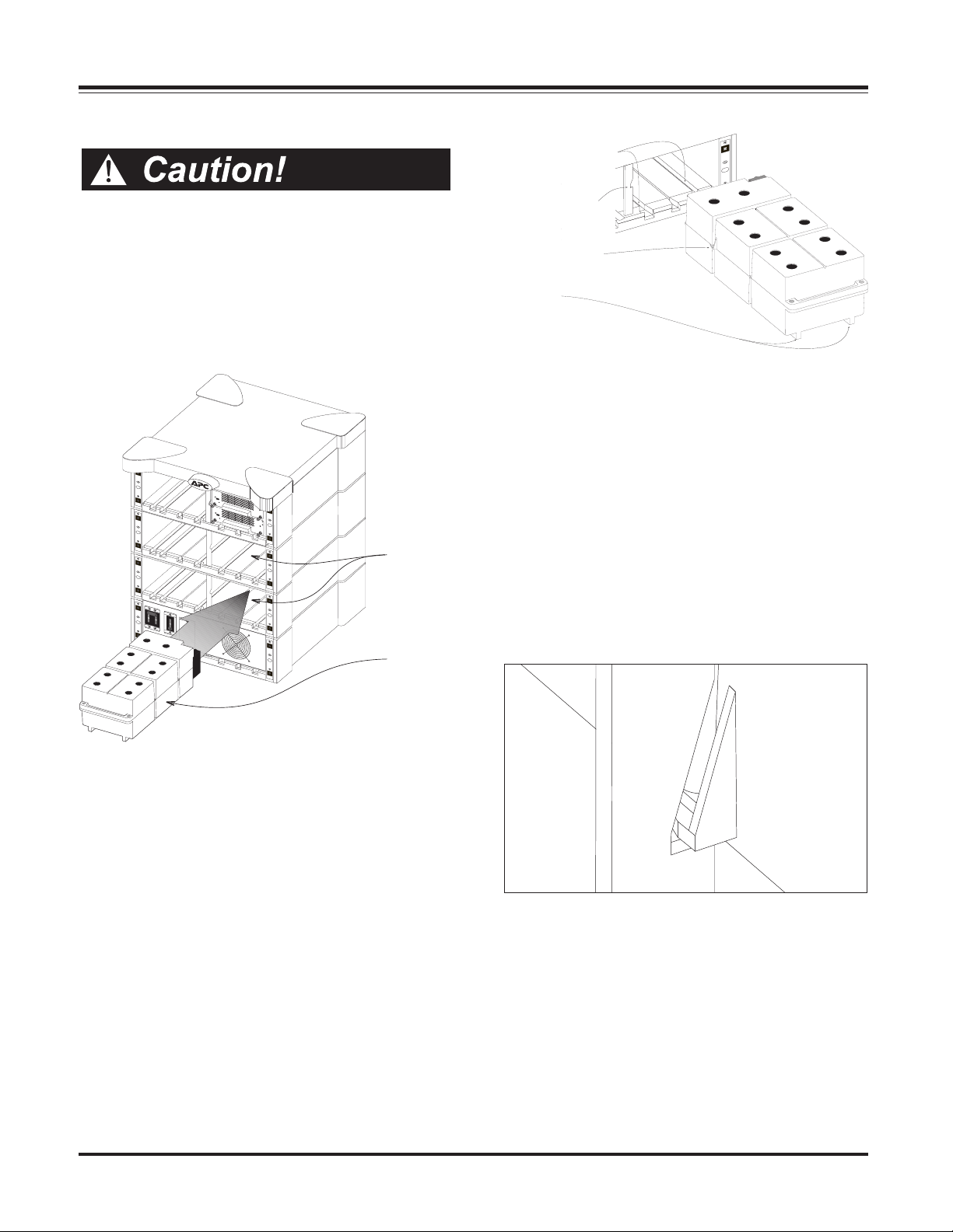
Chapter 5 - System Setup
Installing the Battery Modules
Alignment Grooves
n Each battery module weighs 60 lb. Battery module
installation and handling requires two people to lift
the module.
Procedure for Battery Module Installation
1. Clear all battery module bays of any debris. Make sure the
alignment tracks are clear, and free of obstruction.
Battery
Module
Bays
Battery
Module
Retaining Notch
Battery Module
Retaining Flange
Runners
Fig 5-3 Battery Alignment Grooves and Runners
3. With one person on either side of the battery module, lift
the module, align the runners with the alignment grooves, and
slide module into the bay.
Note: When installing power or battery modules, always install
them in the lowest available bays. Installing modules in this
manner minimizes lifting, and lowers the center of gravity of the
Power Array system.
4. As the battery module slides into the bay, the retaining
flange will fall behind the notch in the frame. See figure 5-4.
When a battery module is being removed, this flange prevents
the battery from falling out of the bay until both people have
assumed the full weight of the module.
Fig 5-2 Location of Battery Module Bays
2. There are two alignment grooves molded into the bottom
of the battery module bay. These correspond with runners
that are molded into the bottom of the battery module.
See figure 5-3.
5-2
Fig 5-4 Battery Module Retaining Flange
5. To engage the internal electrical connector, the battery module must be swiftly and firmly pushed into place. The design
of the battery module incorporates a “drop lock” that will
engage when the battery module is properly seated in the bay.
If the internal connector does not engage, a slight tug will move
the module. If it is locked, the battery module will not move,
and must be slightly lifted before it can be pulled from the bay.
Page 40

Chapter 5 - System Setup
Installing the Power Modules
The vertical column of bays at the left of the frame house the
power modules. See Figure 5-5.
Procedure for Power Module Installation
1. Clear all power module bays of debris. Make sure the
alignment grooves are clear, and free of obstruction.
Note : The PowerView cable must be held up and out of the way,
while a power module is installed in bay “L1.”
Power
Module
Bays
4. Make sure the alignment grooves and the runners are lined
up. Slide the power module into bay. See figure 5-6.
5. To engage the internal connector, slide the power module
firmly into the bay. The “drop lock” tabs will fall into place.
See figure 5-7.
Drop Lock
Seating Tabs
Power
Module
Fig 5-5 Location of the Power Module Bays
2. There are two alignment grooves molded into the bottom
of the power module bay. These correspond with runners
that are molded into the bottom of the power module.
See figure 5-6.
Alignment
Grooves
Runners
Fig 5-7 Seating Tabs When Module is Properly Installed.
6. Swing the flip latch up and fasten the captive screw into the
module. Gently tighten screw until it is firmly in place. DO
NOT overtighten screw.
Note: The flip latch will not engage if the power module is not
fully seated into the bay. The flip latch activates a micro switch
inside the power module. If the latch is not properly installed,
the power module will not function. If after installing the power
module, the flip latch will not engage, pull the power module out
of the bay, and firmly slide it into place.
Fig 5-6 Power Module Alignment Grooves and Runners
Fig 5-8 The Power Module Flip Latch
5-3
Page 41

Chapter 5 - System Setup
Installing the Main Intelligence
Module (MIM)
The main intelligence module is factory installed. The following procedures is provided in the event that the module is
removed, or needs to be replaced.
Procedure for Main Intelligence Module
(MIM) Installation
1. The main intelligence module fits into a bay at the upper
right corner of the Power Array frame.
Note: The main intelligence module is always installed in the
bottom of this bay, and the redundant intelligence module is
always installed in the top.
2. Carefully align the installation rail on the MIM, with the
track that runs along the inside of the bay.
4. Slide the MIM into the bay.
5. Tighten the two retaining screws. Do not overtighten.
6. Swing the flip latch into place, and tighten the screw. Do not
overtighten.
Installing the Redundant
Intelligence Module (RIM)
The redundant intelligence module is factory installed. The
following procedures is provided in the event that the module
is removed, or needs to be replaced.
Procedure for Redundant Intelligence
Module (RIM) Installation
1. The redundant intelligence module fits into a bay at the
upper right corner of the Power Array frame.
Note: The redundant intelligence module is always installed in
the top of this bay, and the main intelligence module is always
installed in the bottom.
2. Carefully align the installation rail on the RIM, with the
track that runs along the inside of the bay.
4. Slide the RIM into the bay.
5. Tighten the two retaining screws. Do not overtighten.
6. Swing the flip latch into place, and tighten the screw. Do not
overtighten.
Fig 5-9 Location of the MIM and RIM
Redundant
Intelligence
Module
(RIM)
Main
Intelligence
Module
(MIM)
5-4
Page 42
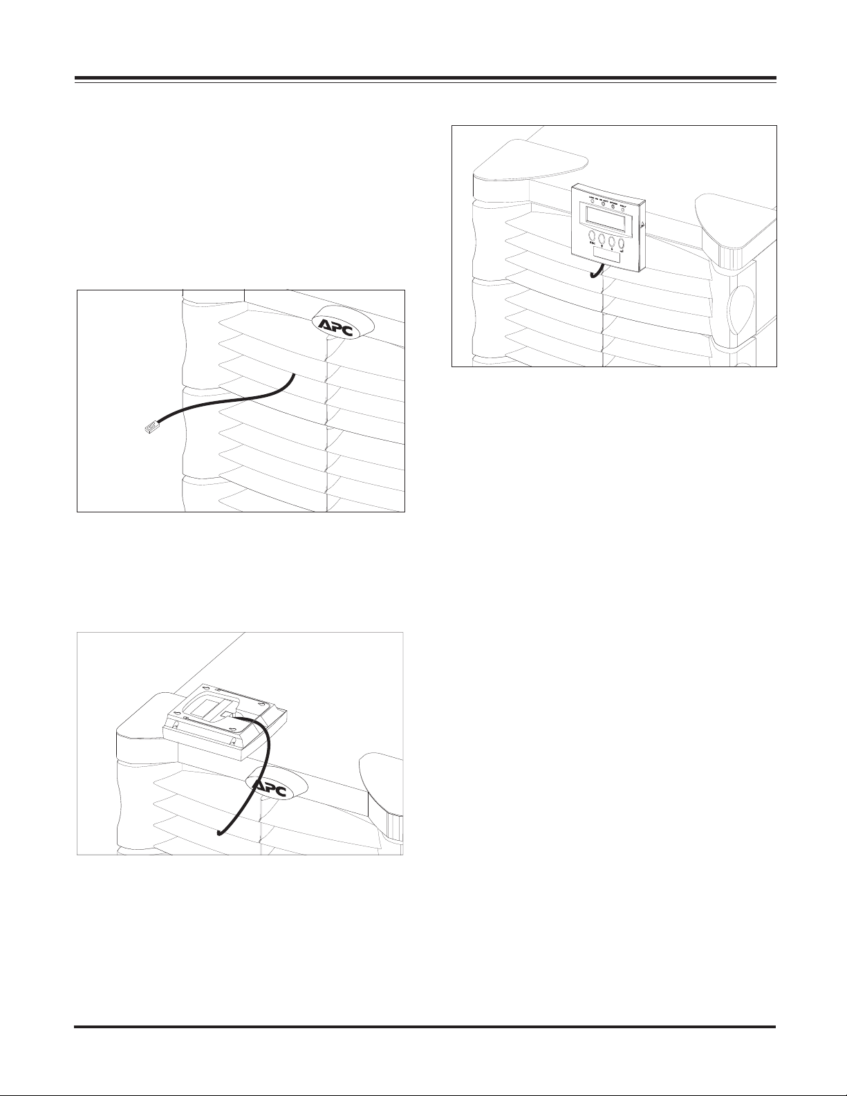
Installing the PowerView Interface
An 18” RJ45 cable (supplied) is provided in bay “L1.” It is used
to connect the PowerView to the Power Array. Use the following procedure to install the PowerView interface to the front of
the frame.
1. Remove the cover grill from the top level of the frame.
2. Feed the end of the RJ45 cable through the center slot of the
top cover grill, and replace the cover grill onto the frame. See
figure 5-10.
Chapter 5 - System Setup
Fig 5-12 Install PowerView Onto Frame
Remote Placement of the PowerView
Fig 5-10 PowerView Cable Through Cover Grill
3. Connect the RJ45 plug into the receptacle on the back of the
PowerView as shown in figure 5-11.
Fig 5-11 Attaching the Cable to the PowerView
The PowerView can be mounted at a remote location, up to 20’
from the frame. Follow the steps below to install PowerView
in a remote location.
1. A 20’ RJ45 cable is included with the SymmetraTM Power
Array.
2. Connect one end of the RJ45 cable to the rear of the Power
Array frame. See figure 1-8 in chapter 1.
3. Connect the other end of the cable to the receptacle at the
rear of the PowerView interface.
4. The short RJ45 cable at the top of power module bay “L1”
can be safely tucked onto the top of the power module. Replace the grill cover.
The PowerView will sit upright on a flat surface, by folding out
the wire bail on the back. It can also be mounted to a wall.
Wall Mounting the PowerView
1. Note the four mounting slots molded into the back of the
PowerView body.
2. Use the template in figure 5-13 to position four large screws
on a clean dry wall surface.
3. Leave the head of each screw 5/16" out from the surface of
the wall. Screws must be able to support 15lb.
4. Mount the PowerView display onto the wall by positioning
it over the screws, and sliding it down until it is securely in
place.
5. Position the PowerView over the mounting post on the
front of the frame, and push straight down. The PowerView
snaps into place. See figure 5-12.
6. Tuck the excess cable into the grill cover.
5-5
Page 43

Chapter 5 - System Setup
SmartSlotTM Interface Accessories
SmartSlotTM bays at the rear of the frame accomodate up to
four accessory cards. SmartSlot
the dealer, or by calling APC at 1-888-809-TECH.
Note: APC has enhanced the SmartSlot
tion with SymmetraTM. Before installing any SmartSlot
cessory, make sure it is a new, “Symmetra
n Share-UPS
TM
SmartSlotTM Accessory Card - Provides au-
tomatic shutdown of up to fifteen servers connected to
the Power Array.
n Control-UPS
TM
/400 SmartSlotTM Accessory Card - Pro-
vides power monitoring and shutdown for an AS/400
system.
TM
cards are available through
TM
Accessories to func-
TM
Compatible” model.
TM
ac-
n Measure-UPS
TM
II SmartSlotTM Accessory Card
Works in conjuction with PowerNet SNMP and
PowerChute Plus software. Provides environmental information such as ambient temperature, and humidity.
Note: If installing more than one accessory card, always
install the Measure-UPS card in the slot that is all the way
to the right.
n Call-UPS
TM
SmartSlotTM Accessory Card
Works with an external modem to provide out-fo-band
UPS management for the Power Array.
See the User's Manual that is included with the SmartSlot
Accessory card for specific installation and operating instructions.
3 1/2
TM
5-6
4
3 1/8
Fig 5-13 PowerView Wall Mounting Template
Page 44

Chapter 5 - System Setup
Installation Test
The following test procedure is intended to ensure that the
MIM, RIM and the power and battery modules have been
correctly installed. It will verify that the SymmetraTM is responding correctly and is ready to deliver power to the load
equipment. It is intended that the installer of the Symmetra
system will perform this test.
Before this test can be conducted, the main intelligence module
(MIM), the PowerView display, at least one power module
and at least one battery module all must be properly installed.
Installation procedures are provided earlier in this chapter.
Note: This test is intended to verify the correct setup and installation of the SymmetraTM system. It is not intended to explain
it’s usage. In this procedure, you will be instructed to ignore
PowerView messages, etc. Refer to chapters 6 & 7 for detailed
information about the operation of SymmetraTM.
Installation Test/Checklist
q 1. Make sure all three switches - system enable, mainte-
nance bypass, and input circuit breaker are in the off or standby
position. Make sure all load equipment is either turned off, or
is unplugged from Symmetra
Note: Load equipment can be left connected during this test
procedure, however power will be switched on and off to the load
equipment. Therefore, it is recommended that load equipment
be switched to the “off” position, until the completion of this
test.
TM
.
TM
q 3. From the startup screen, press the ESC navigation key
to display the top level menu screen. See figure 5-15.
Fig 5-15 Top Level Menu & The Enter Navigation Key
Press the down arrow navigation key to select “Status,” and
then press the enter navigation key. The voltage status screen
appears. See figure 5-16.
Fig 5-16 Voltage Status Screen
Read the voltge status screen to verify that input voltage (Vin)
is nominally either 208V or 240V. Verify that output voltage
(Vout) is approximately 0V.
q 4. Press the down arrow key to scroll to the frequency
status screen. See figure 5-17. Verfiy that the input frequency
is approximately 60 Hz.
Fig 5-17 Frequency Status Screen
q 2. Switch both the input circuit breaker and the system
enable switch to the “on” position. Symmetra
internally, but will not deliver output voltage. The PowerView
will display text. Depending on the configuration of the
Symmetra
tery Modules has changed” may appear. Press the ESC navigation key until the startup screen appears. See figure 5-14.
Verify that the input voltage is 208V or 240V nominal, that the
output voltage reads “000Vout,” and that all four of the
PowerView LED lights are off.
TM
, one or more messages such as “Number of Bat-
Fig 5-14 Startup Screen
TM
will power up
q 5. Press the down arrow key to scroll to the battery status
screen. See figure 5-18. Verfiy that the number of battery
modules reported (01 in the example below) is the same as the
actual number of battery modules that are installed. Verify
that the number of “bad” modules reported is zero. Verify
that there is a minimum of 90V of battery voltage reported.
Note: The reported battery voltage will vary from approximately
90V to 148V, depending on the state of the charge. If the reported
voltage is less than 90V, allow the battery modules to recharge.
(Leave the system enable switch and the input circuit breaker in
the “on” position, and allow the Power Array to remain idle for
approximately one half hour.)
Fig 5-18 Battery Status Screen
5-7
Page 45
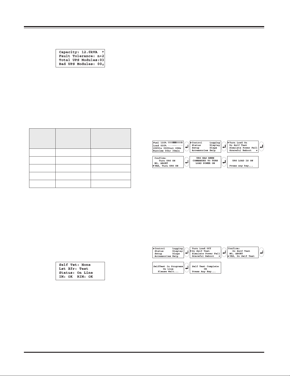
Chapter 5 - System Setup
q 6. Press the down arrow key to scroll to the power mod-
ule status screen. See figure 5-19.
Fig 5-19 Power Status Screen
Verfiy that the number of power modules reported (3 in figure
5-19) is the same as the actual number of power modules that
are installed. Verify that the number of “bad” modules reported is zero. The first line of the power status screen displays the reported capacity of the SymmetraTM. The reported
capacity is dependent upon the number of power modules
installed, and the size of the frame. Use table 5-1 to confirm
that the PowerView is reporting the correct information.
rebmuN
rewoPfo
seludoM
1AVk4AVk4
2AVk8AVk8
3AVk8AVk21
4a/nAVk61
5a/nAVk61
detropeR
niyticapaC
emarFiniM
detropeR
niyticapaC
emarFretsaM
Table 5-1 SymmetraTM Power Module/Frame Capacities
q 7. Press the down arrow key to scroll to the miscellaneous
status screen. See figure 5-20. The bottom line indicates the
status of the MIM and RIM. The sample screen in figure 5-20
indicates that both are installed and functioning properly (OK).
If a module is not installed, the status screen will display the
word “NONE.” Confirm that the status of the MIM and RIM
as indicated by this screen conforms to the actual installation
of those modules. Use the ESC key to return to the startup
screen.
q 8. Use the following steps to deliver output voltage to the
load equipment. See figure 5-21 for the screen sequence.
n Press the ESC navigation key on the PowerView display
until the startup screen appears.
n Press the ESC key to display the top level menu.
n Press the down arrow navigation key, until the cursor is
pointing to “Control.”
n Press the “enter” navigation key.
n Press the down arrow navigation key, until the cursor is
pointing to “Turn Load ON.”
n Press the “enter” navigation key.
n Confirm that you want to turn the load on, by selecting
“YES, Turn UPS ON”
n Several other over-ride messages may appear, depending
on the system configuration. Select “start now” for any
of these startup over-ride messages.
Fig 5-21 Power The Load Sequence
After several seconds, the PowerView display should report
that the “UPS LOAD IS ON.” Press the ESC key to return to the
startup screen. Confirm that output voltage is present, and
that the Load On LED is glowing.
Note : The Bypass LED may flash on briefly, and the On Battery
LED may light for 20-30 seconds if the system is configured for
“self test at power on.”
q 9. Perform a self test by following the screen sequence in
figure 5-22.
5-8
Fig 5-22 Initiate a Self Test Sequence
Fig 5-20 Miscellaneous Status Screen
The On Battery LED should glow for approximately 30 seconds. A message will appear on the display indicating that a
self test is in progress. When the “Self Test Complete” message
appears, press any key to return to the startup screen.
Page 46
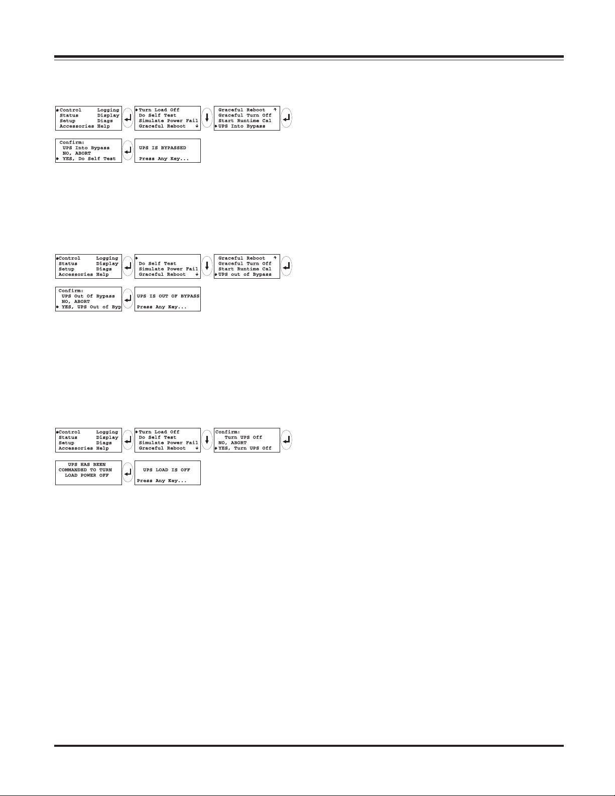
Chapter 5 - System Setup
q 10. Place the Symmetra
TM
into Bypass by following the
screen sequence in figure 5-23.
Fig 5-23 Initiate a Self-Test Sequence
The Bypass LED should light, and the PowerView display will
indicate that the SymmetraTM is bypassed.
q 11. Return the Symmetra
TM
to the on-line mode of opera-
tion by following the screen sequence in figure 5-24.
Fig 5-24 Return to On-Line Sequence
The Bypass LED should go out, and the message “UPS IS OUT
OF BYPASS” will appear on the PowerView display. Press any
key to return to the startup screen.
q 12. Power down the load equipment by following the
screen sequence in figure 5-25.
Fig 5-25 Power Down the Load Sequence
From the Control menu, power down the load equipment by
executing the UPS LOAD OFF command. After several seconds, the “UPS LOAD IS OFF” message is displayed. All LEDs
on the PowerView should be off.
q 13. Power down the Symmetra
enable switch and the input circuit breaker to the “off ” position. The installation procedure has now been completed.
TM
by switching the system
5-9
Page 47

Chapter 5 - System Setup
5-10
Page 48

Chapter Six
PowerView Display
The PowerView Display is used to control the
Power Array, configure functionality, monitor
system components, set alarm thresholds,
and to compile and review a log of power
events. The Powerview contains the audible
and visual alarms that are initiated when an
alarm event occurs.
Page 49

Chapter 6 - The PowerView Display
The PowerView Display
The PowerView Display is the primary user interface for the
SymmetraTM Power Array system. It is used to control the
Power Array, to configure the functionality, monitor the system, set alarm thresholds, and it performs as the audible and
visual alarm.
Physical Features of the Powerview
The PowerView Display incorporates a 4 x 20 LCD with four
navigation keys, four LED lights, and an audible alarm beeper.
It is designed to either mount on the front of the frame, to
stand on top of the frame, or to be installed at a remote location. A local RJ45 connector cable is hardwired to the top
power module bay (L1), and is used to connect the display
when it is mounted onto the frame. A 20’ RJ45 cable is provided with the system for positioning the PowerView at a remote location.
PowerView Functions
An overview of each of the PowerView interface functions is
provided below:
n User Interface - The PowerView is the primary user in-
terface for the system. It is used to command the system
to power up, and power down the load, as well as to check
the status of system components, and to configure the
functionality of the system.
n Alarms and Alarm Thresholds - The PowerView con-
tains an audible and visual alarm system. In the event of
a power disturbance, or loss of a system component, (and
other user-configured alarm conditions), the PowerView
interface emits both an audible alarm and displays a visual message.
As an example, if a Power Array has been configured with
an N+1 redundancy, the PowerView can be configured so
that an audible alarm will sound if the system looses the
redundant power module. (Typically, this would be the
result of an additional load being added, or a power module failure.) Other user configurable alarms include load
size threshold and minimum runtime threshold. Procedures for setting user configurable parameters are provided in Chapter 7. All PowerView display messages, and
the corrective actions are listed in Chapter 9.
Fig 6-1 The PowerView Interface
n Set System Function Parameters - The PowerView can
be used to set parameters for the functioning of the Power
Array. These include acceptable input and output frequency ranges, frequency of self tests, and minimum/
maximum settings for power transfers.
n Powerview Interface Parameters - The PowerView can
be used to set the contrast of the LCD screen, select the
information that is displayed in the startup screen, set the
time, date, password and the audible alarm volume.
n Event Logging - The last 64 power and user events are
recorded and accessible via the PowerView interface. The
category of events that are logged is configurable. Statistics are compiled and can be reviewed using the PowerView.
n Check Status and Diagnostics - Input voltage, output
voltage, available runtime, load size, current operating
mode and the status of each power and battery module
are reported by the PowerView interface.
n Testing - The PowerView interface can be used to per-
form a system self test and to simulate a power failure.
n Help Function - Pressing the up and down navigation
keys simultaneously launches context sensitive help.
6-1
Page 50

Chapter 6 - The PowerView Display
PowerView LED's
Four LED indicators report the operational status of the Power
Array. Table 6-1 describes the function of each of the LED
indicators.
DEL roloC noitpircseD
DAOL
NO
NO
TTAB
neerG -no,lamronsetacidnI
gnitarepoenil
rewoPehT.noitidnoc
si,nosiyarrA
morfrewopgniviecer
sidna,ytilitueht
,naelcgniylppus
otrewopdenoitidnoc
.daoleht
wolleY ytilituatahtsetacidnI
saheruliafrewop
tahtdna,derucco
dehcattaehtotrewop
deilppusgniebsidaol
yrettabehtyb
.seludom
Navigation Keys
The four navigation keys located on the front of the Powerview
interface are used to move through the screen menus, select
menu items, and to either access information, or change system parameters. A small arrow at the left side of the display
screen indicates which menu item or parameter is selected. The
navigation keys are described in Table 6-2.
SSAPYBwolleY rewoptahtsetacidnI
TLUAFdeR ehttahtsetacidnI
).noitca
Table 6-1 Power Array Display LEDs
gniebsidaolehtot
morfyltceriddeilppus
ehT.ytiliturewopeht
neebsahyarrArewoP
devomerylevitceffe
.tiucricehtmorf
sahyarrArewoP
lanretninadetceted
nA.noitidnoctluaf
lliwegassemmrala
ehtnoraeppa
.yalpsidweiVrewoP
rof9retpahCeeS(
Table 6-2 Navigation Keys Descriptions
evitcerrocetairporppa
6-2
Page 51

Chapter 6 - The PowerView Display
The Startup Screen
When the system enable switch is switched to the “on” position, the “Startup Screen” appears. See figure 6-2. This screen
is the factory default, and can be user configured to display
other information. Note that all PowerView screens will “time
out” after ten minutes of inactivity. It reappears when any
navigation key is touched. The startup screen displays the
following information:
n Fuel Percentage - The first line indicates the percentage of
battery capacity (fuel) that is currently available.
n Load Percentage - The second line indicates the percent-
age of system capacity that is employed supporting the
current load.
n Voltage and Input Frequency - The third line indicates
the input voltage, output voltage, and the input frequency.
n Run time - The fourth line indicates the run time that can
be expected, based upon the current load, and battery
capacity.
The Top-Level Menu Screen
When the startup screen is displayed, pressing any of the navigation keys opens the “Top-Level Menu” screen. This screen
contains seven menu items, and a context sensitive help function. See Figure 6-3.
Fig 6-3 Top-Level Menu Screen
The top-level menu screen is analogous to a menu bar at the
top of a computer software interface. Selecting any of the
seven menu items, and pressing the “enter” key opens a submenu. Menu items and functions are outlined below. In Chapter 7, the PowerView interface is used to power up the load
equipment. Many of the following PowerView functions are
explained in those procedures.
Fig 6-2 Startup Screen
Control
n Power up and power down the load equipment
n Simulate a power fail
n Graceful reboot
n Graceful turn off
n Start run time calibration
n Put system into or out of bypass mode
Status
n Determine input/output voltage and frequency
n Determine the % load - no redundancy
n Determine the % load - with redundancy
n Review input/output frequencies
n Review status of battery modules
n Review status of power modules
n Review alarm thresholds
n Determine current operation mode,
n Review status of the main intelligence module
n Review status of the redundant intelligence module
6-3
Page 52

Chapter 6 - The PowerView Display
Setup
n Set the system shutdown parameters
n Set the alarm thresholds
n Set input/output frequency sync range
n Set system to either go, or not go to bypass if frequency
sync is out of range when a power module failure occurs
n Set “self test at power up” on or off
n Set system ID
n Set output voltage
n Copy system settings
Accessories
n Monitors SmartSlot
TM
Accessory cards (if present)
Logging
n View the last 64 power or user events
n Select which events are to be recorded in the event log
n Clear event log
n View statistical representation of log data
n View events by the individual groups that are
being logged
Display
n Configure the date and time
n Set a password
n Display the “about system” information
n Set audible alarm parameters and volumes
Note: This function is used to switch off the beeper alarm.
n Set screen contrast
n Configure the startup screen
Diagnostics
n Display the reason a failure, change or alarm has occurred
n Check the Intelligence Module
n Check the Redundant Intelligence Module
n Check the UPS modules
n Check the Battery modules
Help
n Provides context sensitive help
6-4
Page 53

Chapter Seven
Configuring & Operating
TM
the Symmetra
This chapter includes the procedures to use
the PowerView to configure the system, and
to initiate delivery of conditioned power to
the load equipment. You will use the
PowerView interface to set the configuration
variables and alarm thresholds, and to
review the status of the components of the
system. Also included is the procedure for
reviewing the power and user events log.
Page 54

Chapter 7 - Configuring & Operating the Symmetra
TM
Introduction
The following pages comprise the inital configuration of the
SymmetraTM system. Read and follow these steps carefully.
When they are completed, the Power Array system will be
configured to provide optimal power protection for the data
center, or other load equipment.
The following procedures assume that the Power Array system is not yet powered. If the Power Array is already powered, check to make sure the loads are in a safe state to be
switched off, and then switch the load equipment off. Switch
the system enable switch and the input circuit breaker to the
“stand by” position. Switch the maintenance bypass to the
“off” position.
Note: Refer to chapter 1 for the location of the switches.
Step 1: Powering the Power Array
In this step the Power Array is powered, while the loads remain unpowered.
1. Make sure all input, output and EPO wiring has been installed by a licenced electrican. Check to insure that the
electrican has completed the electrical wiring test/checklist
at the end of chapter 4. Make sure all modules and the
PowerView are installed correctly, and that all front grill covers have been replaced onto the frame.
2. Switch the input circuit breaker to the “on” position. The
Power Array is now connected to utility voltage.
3. Switch the system enable switch to the “on” position. The
startup screen will appear on the display.
Note: When the system enable switch is switched to the “on”
position, the Power Array runs through a series of internal tests.
Allow the Power Array to start up for a minimum of 10 seconds,
before entering commands into the PowerView interface.
Fig 7-1 Startup Screen
4. The first line of the startup screen displays the battery
capacity.* The second line displays the load capacity. This
displays 000% because the load is not powered yet. The third
line displays the input and output voltage, and the input frequency. Again, the output voltage should read “000Vout”
because the load has not been powered. The fourth line displays the predicted run time for the current load. Until the
load is powered, this run time will not be meaningful.
* Under ideal conditions, the batteries would be at 100% capacity. Typically, there will be some battery discharge during
handling and shipping of the Power Array. If batteries are showing less than 50% capacity, allow the batteries to charge before
proceeding. (Leave the system enable switch and the input circuit breaker in the “on” position.)
7-1
Page 55
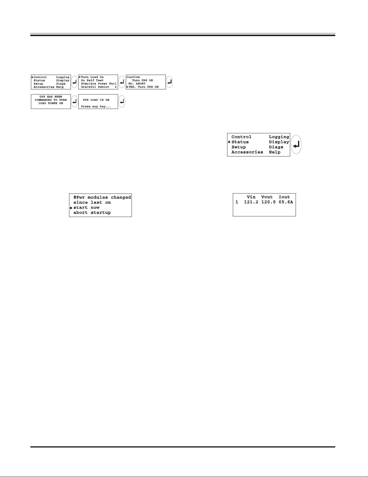
Chapter 7 - Configuring & Operating the Symmetra
TM
Step 2: Powering the Loads
1. Use the sequence in figure 7-2 on the PowerView interface
to enter the “Turn Load On” command.
Fig 7-2 “Turn Load On” Command Sequence
2. The Power Array has now been instructed to power up the
load equipment. It conducts a self diagnosis, and determines
if the conditions are appropriate to power the load. Depending on the diagnostics, the Power Array will either power the
load, or one of several startup over-ride messages will appear. A startup over-ride message indicates an exceptional
condition exists, and gives the option to proceed or abort.
An example startup over-ride message is displayed below:
Fig 7-3 Sample Startup Over-Ride Message
For this initial sequence, select “start now” for any startup
over-ride message that may appear.
Note: If an alarm sounds, and a “fault message” appears, see
chapter 9 for the cause, and the corrective action.
3. When the load has been successfully powered, the green
“LOAD ON” LED will glow, and the message “UPS LOAD IS
ON” will appear on the screen.
Note: The yellow "ON BATT" LED will glow momentarily,
while the system is conducting the self test.
4. Press the Escape key and return to the startup screen.
Note: The output voltage now registers on the display, and the
load percentage and run time are now based on the actual load.
Step 3: Review Status Conditions
In this step, the status conditions of the Power Array are accessed with the PowerView. Status information is used as
“reference” information about the condition of the Power
Array, and the modular components. Review the following
status screens for content. Status information is accessed via
the “Status” menu item on the top level menu.
Position the arrow cursor next to the “Status” menu item on
the top level menu screen. Press enter. The voltage status
screen appears.
Fig 7-4 Opening the Status Menu Item
Voltage Status Screen
Fig 7-5 Voltage Status Screen
The voltage status screen displays the following information:
Input Voltage - the actual input voltage from the utility
source.
Output Voltage - the actual output voltage.
Load Current - the amperage drawn by the load.
After the voltage status screen has been reviewed, press the
enter key. The load with redundancy status screen appears.
7-2
Page 56

Chapter 7 - Configuring & Operating the Symmetra
TM
% Load With No Redundancy Status Screen
Fig 7-6 Percent Load With No Redundancy Status Screen
% Load Assuming No Redundancy - displays the percent of
the total Power Array capacity that is required by the load.
The total Power Array capacity is defined by the number of
power modules installed, multiplied by 4kVA and is limited
by the kVA rating of the frame. See table 7-2. After this screen
has been reviewed, press the enter key. The percent load with
redundancy status screen appears.
% Load With Redundancy Status Screen
Fig 7-7 Percent Load With Redundancy Status Screen
% Load Allowing For Redundancy - displays the percent of
the non-redundant Power Array capacity that is required by
the load. The non-redundant Power Array capacity is defined
by the number of user defined non-redundant power mod-
ules installed, multiplied by 4kVA and is limited by the kVA
rating of the frame. See table 7-1. After the load with redundancy status screen has been reviewed, press enter. The frequency status screen appears.
Note: The redundancy level for this measurement is user defined,
and will be assigned in Step 6 of this procedure. Either zero, one
or two power modules will be designated as “redundant.” The
remaining power modules are then defined as “non-redundant.”
Frequency Status Screen
Fig 7-8 Frequency Status Screen
Frequencies - displays the input frequency that is being received from the utility power source, and the output frequency
being delivered to the load equipment. After the frequency
status screen has been reviewed, press enter. The battery status screen appears.
Battery Status Screen
Fig 7-9 Battery Status Screen
Battery Status Screen - displays battery voltage, the percentage of available battery capacity, number of battery modules
that are installed, number of battery modules that are “bad”
and the predicted run time. Use this screen to check the status of the battery modules. After the battery status screen
has been reviewed, press enter. The power status screen appears.
Note: If a battery module is diagnosed as “bad,” see chapter 8.
Power Status Screen
Fig 7-10 Sample Power Status Screen
Table 7-1 Non-Redundant Power Array Capacities
Power Status Screen - the reported Power Array capacity is
dependent upon the number of power modules installed, and
the size of the frame. Use table 7-2 to confirm that the
PowerView is reporting the correct information.
Table 7-2 SymmetraTM Power Module/Frame Capacities
7-3
Page 57

Chapter 7 - Configuring & Operating the Symmetra
TM
The power status screen also displays the actual level of fault
tolerance, the number of power modules in the frame, and
the number of “bad” power modules. The actual fault tolerance indicates the number of functioning power modules in
the Power Array, minus the number required to power the
load. (i.e., If a load is 6kVA, two modules are required. If
there are five modules installed, the fault tolerance would read
N+3.) Use this screen to check the status of the power modules. After this screen has been reviewed, press enter. The
alarm threshold status screen appears.
Note: If a power module is diagnosed as “bad,” see chapter 8.
Alarm Threshold Status Screen
Fig 7-11 Sample Alarm Threshold Status Screen
Alarm Thresholds - The alarm threshold status screen displays the user-defined fault tolerance threshold. An audible
alarm will sound if the level of redundancy drops below this
level. This screen also displays a user specified load threshold. An audible alarm will sound if the attached load exceeds this threshold. Finally, the run time alarm threshold is
displayed. An audible alarm will sound if the predicted run
time becomes less than this threshold (either because of loss
of battery capacity, or increased load). After the alarm threshold status screen has been reviewed, press enter. The miscellaneous status screen appears.
Note: Alarm thresholds will be set in Step 4.
Step 4: Perform a Self Test
A Power Array self test measures system performance by sequentially placing each power module on battery, and then
briefly placing all of the power modules on battery.
1. The following sequence on the PowerView will initiate a
system self test:
Fig 7-13 Initiate a Self Test Sequence
2. The PowerView displays the message "Self Test In Progress"
while the Power Array system performs the test.
Note: The Power Array will make a series of clicking sounds
during a self test.
3. The PowerView will either report that the self test was
completed with no errors, or will report any failures detected.
4. Press the escape key and return to the startup screen.
Miscellaneous Status Screen
Fig 7-12 Sample Miscellaneous Status Screen
The Miscellaneous Status Screen - displays the following information:
Self Test - the results of the last self test perfomed by the
Power Array.
Last transfer - displays the reason for the last transfer to battery.
Status - identifies the current mode of operation.
Note: See the “Introduction” for details about operating modes.
IM - displays the status of the main intelligence module.
RIM - displays status of the redundant intelligence module.
The miscellaneous status screen is the final status screen. Press
the Escape key to return to the startup screen.
7-4
Page 58

Chapter 7 - Configuring & Operating the Symmetra
TM
Step 5: Configure Shutdown Parameters
Specific shutdown parameters can be configured into the
PowerView. Follow this procedure to configure the shutdown
parameters that best fit best fit the data center requirements.
The following sequence on the PowerView opens the shutdown parameter selection screen:
Fig 7-14 Shutdown Parameter Selection Sequence
Shutdown Parameter Selection Screen
Fig 7-15 Shutdown Parameter Selection Screen
Each line of the shutdown parameter selection screen contains a configuration parameter. To set a parameter, select a
line and press the enter key. Note the flashing up/down arrow
appears. Select the desired parameter by scrolling up or down
through the choices using the arrow navigation keys. When
the desired parameter is displayed, press the enter key. The
parameter is then recorded into the PowerView memory.
Line #1: Low Battery Duration - When in the on battery mode,
the Power Array will signal an alarm 2, 5, 7 or 10 minutes
before system shutdown occurs due to battery exhaustion.
Make selection based on the time required to gracefully shutdown the load equipment in the data center.
Line #2: Shutdown Delay - many computer networks that
issue shutdown commands will require some additional run
time after that command is issued to gracefully shut themselves down. If your computer network is one of these, the
Power Array provides a choice of a 20, 180, 300 or 600 second
delay from the receipt of the shutdown command, to when
the Power Array stops powering the load equipment.
Line #3: Return Delay - when utility power is restored after a
failure, a delay interval may be desirable, to allow utility power
to stabilize before the system goes back on line. The return
delay interval can be set to 0, 60, 180 or 300 seconds.
Line #4: Return Battery Capacity - When returning from an
extended power failure, a minimum battery capacity is often
desired before repowering the load. The settable values for
this paramer are 0, 10, 25 and 90%. This minimal requirement insures there will be sufficient battery run time to safely
shutdown the load in the event of a subsequent power failure.
Press the enter key to record your selection, and then press
escape to return to the startup screen.
Step 6: Configure Alarms
Specific alarm parameters can be configured into the
PowerView. Follow this procedure to set the alarm thresholds that best fit the data center requirements.
Use the following sequence on the PowerView to open the
alarm thresholds selection screen:
Fig 7-16 Opening the Alarm Thresholds Selection Screen
Alarm Thresholds Selection Screen
Fig 7-17 Alarm Threshold Selection Screen
Each line of the alarm threshold selection screen contains a
configuration parameter. To set a parameter, select a line
and press the enter key. Note the flashing up/down arrow
appears. Select a desired alarm parameter by scrolling up or
down through the choices using the arrow navigation keys.
When the desired parameter is displayed, press the enter key.
The parameter is then recorded into the PowerView memory.
Line #1: Redundancy Alarm Threshold - The Power Array
will signal an alarm if redundancy falls below this threshold.
Base this selection on the number of power modules present
(4kVA each), the size of the load, and the power module redundancy requirements. If redundant power modules are
installed, it is highly recommended that this threshold be set
so that the alarm will be initiated if the redundancy is lost.
(Possibly as a result of an unauthorized increase of the load.)
Line #2: Maximum Load Threshold - The maximum load
threshold can be set, in increments of 2kVA. If the load exceeds this threshold, the alarm will sound.
Line #3: Minimum Run Time Threshold - The minimum
available run time threshold can be set. In the event that the
predicted run time falls below this threshold, the alarm will
sound.
Switching Audible Alarm Beeper Off
Use the following sequence to access the beeper alarm on/off
command: “Top level menu-Display-Beeper-Vol-select off.”
Note: This silences the audible alarm. It does not resolve the
alarm situation.
7-5
Page 59

Chapter 7 - Configuring & Operating the Symmetra
TM
Step 7: Review Diagnostic Information
The PowerView allows the user to access an extensive set of
self-diagnostics information. Follow this procedure to review the diagnostic screens.
The following sequence on the PowerView opens the diagnostics menu screen:
Fig 7-18 Opening the Diagnostics Menu Screen
Diagnostics Menu Screen
Fig 7-19 Diagnostics Menu Screen
Each line of the diagnostics menu screen contains a menu
selection item. Each of these open subsequent screens as
shown below.
Line #1: Fault & Diagnostics Menu Item - This screen provides an overview of any faults detected within the system. If
a fault is detected, the PowerView will specify which type of
system component has failed.
Line #2: Intelligence Module Diagnostic Menu Item - This
menu item opens the main intelligence module information
screen.
ing up/down arrow appears. Use the arrow navigation keys
to scroll up or down. The status of each module will appear
one at a time. In the event of a power module failure, use
this screen to identify which power module has failed. Use
this screen to confirm that a new module is recognized by
the Power Array, and is functioning properly. (Procedure in
chapter 8.)
Line #4 (right): Battery Diagnostic Menu Item - This menu
item opens the battery module information screen.
Fig 7-22 Battery Module Information Screen
With the flashing arrow cursor pointing at the second line
(as illustrated in figure 7-22), press the enter key. Note the
flashing up/down arrow appears. The status screen for the
battery module in the top battery module bay appears:
Fig 7-23 Top Battery Module Status Screen
This screen indicates that the battery module in bay “R2” is
functioning properly. Use the arrow navigation keys to scroll
through all of the battery module status screens. In the event
of a battery module failure, use this screen to identify the
battery module that has failed. After a battery module is replaced, confirm the new module is recognized by the Power
Array, and is functioning properly. (Procedure in chapter 8.)
Fig 7-20 Intelligence Module Information Screen
The status line at the top of this screen indicates if the main
intelligence module is functioning properly or not. This
screen also provides detailed information about the MIM.
Line #3: Redundant Intelligence Module Diagnostic Menu
Item - This screen opens the redundant intelligence module
information screen. It appears the same as figure 7-20.
Line #4 (left): Power Module Diagnostic Menu Item - This
menu item opens the power module information screen.
Fig 7-21 Power Module Information Screen
With the flashing arrow cursor pointing at the first line (as
illustrated in figure 7-21), press the enter key. Note the flash-
7-6
Step 8: Review Logging Menu
The PowerView records the most recent 64 user or power
events in an electronic log.
The following screen sequence opens the event log screen:
Fig 7-24 Open the Event Log Sequence
Event Log Screen
Fig 7-25 Event Log Screen
Scroll up or down through the log items using the arrow navigation keys. The time, date and the number of the selcted
log item is displayed on the top line. For more information
about a log item, select it, and press the enter key.
Page 60

Chapter Eight
Module Replacement
The modular components of the Power Array
are user replaceable. This chapter provides
the procedures for identifying and replacing
a failed module, and for verifying that the
new module is installed and functioning
properly. A toll-free telephone number is
provided that can be used to contact APC
for replacement modules.
Page 61
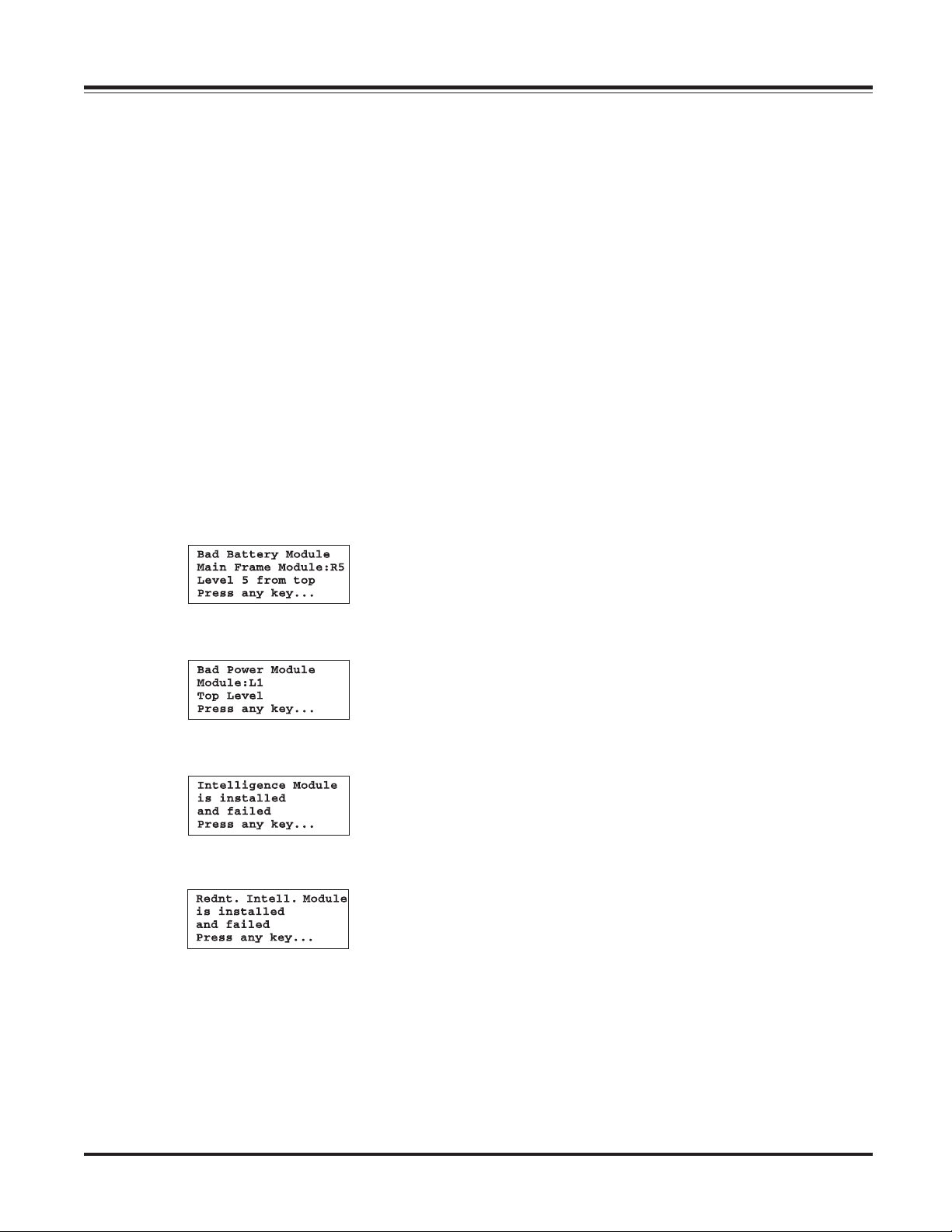
Chapter 8 - Module Replacement
Module Replacement
The battery modules, power modules, intelligence module and
the redudant intelligence module are user replaceable. If any
module fails, and is protected with at least one functioning
“redundant” module, it can be “hot-swapped,” meaning the
failed module can be replaced without interrupting power to
the load equipment.
This chapter explains the alarms that indicate a module failure, it provides a toll-free telephone number for technical support and for ordering replacement modules, and it provides
the procedure for replacing a failed module.
Module Failure Alarm Indicators
In the event of a module failure, the PowerView will display
one of the following four module failure messages. See figures
8-1 through 8-4. In addition to the message, the red Fault LED
status indicator will glow. Depending on the system configuration, other alarms, including the PowerView audible alarm,
a pager notification, and software notification will be issued.
Technical Support and Obtaining a
Replacement Module
To obtain a replacement module, or for technical assistance,
contact APC technical support at 1-888-809-TECH. A technician can help diagnose the situation over the telephone, and
can facilitate obtaining a replacement module.* When contacting APC, be prepared with the following information:
n If possible, contact technical support from a telephone that
is within reach of the Symmetra
aid in using the display to gather and report additional
information to the technician.
n Be prepared to provide a detailed description of the prob-
lem. A technician will help you solve the problem over the
phone if possible, or will give you a Return Material
Authorizaton Number (RMA#). This RMA# must be clearly
printed on the outside of the package if the module is returned to APC.
n If the Symmetra
will be performed free of charge. If it is not within the
warranty period, there will be a charge for repair.
n If the Symmetra
vice Product, have that information available to give to the
technical support technician.
TM
is within the warranty period, repairs
TM
is covered by an APC PowerPlan Ser-
TM
PowerView. This will
Fig 8-1 Battery Module Failure Message
Fig 8-2 Power Module Failure Message
Fig 8-3 Intelligence Module Failure Message
Fig 8-4 Redundant Intelligence Module Failure Message
Each screen clearly identifies which module has failed, and
where to find the module in the SymmetraTM. These locations
match the labels on the center spine behind the grill covers.
The PowerView may display additional screens in the form of
a “fault list.” Press any key to scroll through this fault list.
Record the information on each screen. This information will
aid in the technical diagnosis of the problem.
Returning Modules to APC
To return a failed module to APC, pack the module in the
original shipping container, and return it by insured, prepaid
carrier to the address on the rear cover of this User’s Manual.
If you no longer have the original shiping materials, ask the
technician about obtaining a new set. It is very important that
you pack the module properly to avoid damage in transit.
Never use stryrofoam beads for packaging a module because
the module will settle in transit and become damaged. Damages sustained in transit are not covered under warranty. Enclose a letter in the package with your name, RMA#, address, a
copy of the sales receipt, description of the trouble, a phone
number, and a check (if necessary.)
*If a service contract was purchased from another service provider, contact the service provider for replacement modules,
and technical assistance.
8-1
Page 62

Chapter 8 - Module Replacement
Battery Module Replacement
The following section provides the procedure for replacing a
battery module.
Removing a Battery Module
n The battery module weighs approx. 60 lbs. Two people
are required to lift and handle a battery module.
1. Remove the grill cover from in front of the module to be
replaced. Note that the module bays are labeled to correspond with the PowerView.
2. Battery modules are designed with a “drop lock” that holds
them securely in the Power Array frame. Slightly lift the front
handle of the battery module, and pull it forward to the safety
stop.
3. With one person on either side of the battery module, assume the full weight of the module.
4. The safety stop retaining flange passes through the notch in
the frame as the battery module is removed. See figure 8-5.
Installing the Replacement Module
Refer to chapter 5 for the battery module installation procedure.
Replacement Battery Module Verification
From the startup screen, press any key to open the top level
menu screen. Follow the sequence in figure 8-6 to insure that
the new battery module is recognized by the Power Array system, and is functioning properly. (Status: OK).
Fig 8-6 Replacement Battery Module Verification
Fig 8-5 Battery Module Retaining Flange
5. If the module has failed and needs to be disposed of, return
it to the appropriate service provider, or directly to APC for
recycyling.
Note: The Battery Module contains sealed, non-spillable lead
acid batteries. These must be recycled or disposed of properly.
8-2
Page 63

Power Module Replacement
The following section provides the procedure for replacing a
power module.
Removing the Power Module
1. Remove the grill cover from in front of the module to be
replaced. Note that the module bays are labelled to correspond with the PowerView display.
2. If replacing a non-redundant power module, or if the power
module to be replaced is the only power module present, the
SymmetraTM must be placed in manual bypass mode, or the
load equipment must be switched off. To place the Symmetra
in manual bypass, switch the maintenance bypass switch to
the “on” position.
Note: When the SymmetraTM is in bypass mode, the load equipment is unprotected from power failure.
3. Use a flathead screwdriver to release the fliplatch from the
power module. See figure 8-7.
TM
Chapter 8 - Module Replacement
Drop Lock
Seating Tabs
Fig 8-7 Release the Flip Latch
4. Note the two drop lock seating tabs at the front of the
power module. See Figure 8-8. These are designed to hold the
module firmly in the Power Array frame. When removing a
failed power module, lift the front of the module slightly to
release the drop lock seating tabs, and then pull the module
from the bay.
5. Remove the power module from the frame. If the module
has failed and needs to be disposed of, return it to the appropriate service provider, or directly to APC.
Fig 8-8 Drop Lock Seating Tabs
Installing the Replacement Module
Refer to chapter 5 for the power module installation procedure.
Note: If SymmetraTM was placed in manual bypass in step 2
above, return to normal operation by switching the maintenance bypass switch back to the “off” position.
Replacement Module Verification
From the startup screen, press any key to open the top level
menu screen. Follow the sequence in figure 8-9 to insure that
the new module is functioning properly. Note that the up/
down cursor appears, and the information for each power
module is reviewed by pressing the up or down navigation key.
Make sure all power modules display a status of “On & OK.”
Fig 8-9 Power Module Verification
8-3
Page 64

Chapter 8 - Module Replacement
Main Intelligence Module
Replacement
The following section provides the procedure for replacing the
main intelligence module.
Removing the Main Intelligence Module
1. Remove the grill cover from the top level of the Power Array.
Note: The intelligence module resides under the redundant intelligence module, in the upper right corner of the frame.
2. If a functioning RIM is not installed, the SymmetraTM must be
placed in manual bypass mode, or the load equipment must be
switched off. To place the SymmetraTM in manual bypass, switch
the maintenance bypass switch to the “on” position.
Note: When the SymmetraTM is in bypass mode, the load equipment is unprotected from power failure.
3. If a functioning RIM is installed, it will provide limited control
of the SymmetraTM until the replacement MIM is installed.
4. Use a flathead screwdriver to release the fliplatch.
5. Unscrew and release the retaining screws.
6. Slide the MIM out of the frame.
Installing the Replacement Main Intelligence
Module
Refer to chapter 5 for the MIM installation procedure.
Note: If SymmetraTM was placed in manual bypass in step 2 above,
return to normal operation by switching the maintenance bypass
switch back to the “off” position.
Redundant Intelligence Module
Replacement
The following section provides the procedure for replacing the
redundant intelligence module.
Removing the Redundant Intelligence
Module
1. Remove the grill cover from the top level of the Power Array.
Note: The redundant intelligence module resides above the intelligence module, in the upper right corner of the frame.
2. A RIM can only be replaced if a functioning MIM is installed,
or the load equipment is switched off.
3. Use a flathead screwdriver to release the fliplatch.
4. Unscrew and release the retaining screws.
5. Slide the RIM out of the frame.
Installing the Replacement Redundant
Intelligence Module
Refer to chapter 5 for the RIM installation procedure.
Note: A RIM alone is not adequate to restart the SymmetraTM.
Replacement Redundant Intelligene Module
Verification
From the startup screen, press any key to open the top level menu
screen. Follow the sequence in figure 8-11 to insure that the
replacement RIM is functioning properly. (Status: On & OK).
Replacement MIM Verification
From the startup screen, press any key to open the top level menu
screen. Follow the sequence in figure 8-10 to insure that the
replacement MIM is functioning properly. (Status: On & OK).
Fig 8-10 Intelligence Module Verification
Fig 8-11 Redundant Intelligence Module Verification
8-4
Page 65

Chapter Nine
PowerView Display Messages
As the SymmetraTM monitors the system, it
reports various messages on the display,
including alarm status, changes in system
configuration, etc. This chapter provides a
list of these messages and what each of
them means. It provides the appropriate
corrective action for each of the messages.
Note that more than one of these messages
may occur at one time. If this occurs, review
all of the messages for a better under-
standing of the system condition.
Page 66

Chapter 9 - PowerView Display Messages
weiVrewoP
gninaeM noitcAevitcerroC
egasseM
pU-tratS
degnahcseludomrwP#
.NOtsalecnis
MT
artemmySeht
saheludomrewopenotsaeltA
morfdevomerro,deddaneeb
tsalehtecnis
sawdnammocNOrwPehtemit
.deussi
ecnisdegnahcseirettaB#
.NOtsal
MT
artemmySeht
saheludomyrettabenotsaeltA
morfdevomerro,deddaneeb
tsalehtecnis
sawdnammocNOrwPehtemit
.deussi
ecnegilletnItnadnudeRoN
.dellatsniMIRonsierehTtrobaro,putratsehthtiwdeecorP
.eludoM
:etoN ,MIRgninoitcnufatuohtiW
.eruliafMIMafo
nahtsselyticapacttaB
paCttaBnruteR
MT
artemmyS
ehtfoyticapacyrettabehT
resuehtnahtsselsi
yrettabmuminimdeificeps
1#noitpO dna,putratsehttrobA:
2#noitpO htiw,putratseunitnoC:
ehtnonrutotderiuqeryticapac
.daol
.yrassecennoitcaevitcerrocoN
.putratsehthtiwdeecorP
.yrassecennoitcaevitcerrocoN
.putratsehthtiwdeecorP
.MIRallatsnidna,putratseht
tneveehtniycnadnuderonsiereht
.egrahcerotseirettabwolla
.yticapacyrettabmuminimnahtssel
edistuoqerFtupnI
egnarderugifnoc
MT
artemmyS
ehtotycneuqerftupniehT
ehtedistuosi
tuptuoehT.egnarderugifnoc
ezinorhcnystonlliwycneuqerf
.ycneuqerftupniehthtiw
.elbaliavatonsissapyblamroN
1#noitpO ycneuqerfehtevorpmI:
.egatlovgnimocniehtfo
2#noitpO ehtfoegnarehtnediW:
htiwycneuqerfgnimocnielbatpecca
-puteS-putratS(.weiVrewoPeht
).tceleS-qerFtuptuO
3#noitpO .putratshtiwdeecorP:
.elbaliavatonsissapyblamroN
tubSPUrofetauqedaCA
MT
artemmySehT
ssapybrofton
noitcnuflliw
tub,egatlovtupniehthtiwenilno
sissapybtahttneveehtni
tonsiegatlovtupnieht,deriuqer
1#noitpO gnimocniehtevorpmI:
.egatlov
noitpO2# .putratshtiwdeecorP:
.elbaliavatonsissapyblamroN
daolehtrewopotetauqeda
.tnempiuqe
putrats,tupniCAoN/woL
yrettabno
MT
artemmySehttrats
MT
artemmyS,sdeecorp
otetauqedatonsiegatlovtupnI
putratsfI.
lliw
.yrettabmorfnoitcnuf
1#noitpO litnuputratstrobA:
.tneserpsiegatlovtupnielbatpecca
2#noitpO .putratshtiwdeecorP:
.degrahcsideblliwyrettaB
9-1
Page 67

Chapter 9 - PowerView Display Messages
weiVrewoP
gninaeM noitcAevitcerroC
egasseM
lareneG
sutatS
.desaercniseirettabfo#
.desaercedseirettabfo#
seludoMrwPfo#
.desaercni
seludoMrwPfo#
.desaerced
eludoMecnegilletnI
MT
.detresni
.
artemmyS
eludoMecnegilletnI
devomer
MT
artemmyS
.
ecnegilletnItnadnudeR
MT
.detresnieludoM
.
artemmyS
saheludomyrettabenotsaeltA
.metsysehtotdeddaneeb
saheludomyrettabenotsaeltA
.metsysehtmorfdevomerneeb
saheludomrewopenotsaeltA
.metsysehtotdeddaneeb
saheludomrewopenotsaeltA
.metsysehtmorfdevomerneeb
ehtotnidellatsnineebsahMIMA
ehtmorfdevomerneebsahMIMA
ehtotnidellatsnineebsahMIRA
.yrassecennoitcaevitcerrocoN
.yrassecennoitcaevitcerrocoN
.yrassecennoitcaevitcerrocoN
.yrassecennoitcaevitcerrocoN
.yrassecennoitcaevitcerrocoN
.yrassecennoitcaevitcerrocoN
.yrassecennoitcaevitcerrocoN
ecmegilletnItnadnudeR
.devomereludoM
MT
artemmyS
.
yrettaBlanretxEfo#
.desaercnistenibaC
yrettaBlanretxEfo#
.desaercedstenibaC
artemmySehtmorf
yrettablanretxeenotsaeltA
MT
.
ehtmorfdevomerneebsahMIRA
tenibacyrettablanretxeenotsaeltA
.emarfehtotdetcennocneebsah
detcennocsidneebsahstenibac
.yrassecennoitcaevitcerrocoN
.yrassecennoitcaevitcerrocoN
.yrassecennoitcaevitcerrocoN
ycnadnudereludomrewopfossolA
.derotserneebsahdna,derrucco
derotseRycnadnudeR
neebevahseludomlanoitiddarehtiE
.yrassecennoitcaevitcerrocoN
neebsahdaolehtro,dellatsni
.decuder
daolehtdedeecxedahdaolehT
evobaregnoLoNsidaoL
dlohserhTmralA
sahnoitautisehT.dlohserhtmrala
ehtesuacebrehtiedetcerrocneeb
.yrassecennoitcaevitcerrocoN
dlohserhtehtro,desaerceddaol
.desaercnisaw
depporddahemitnurmetsysehT
dna,muminimderugifnocehtwoleb
lanoitiddarehtiE.derotserneebsah
.derotseremitnuRniM
eht,dellatsnierewseludomyrettab
.yrassecennoitcaevitcerrocoN
,degrahcerseludomyrettabgnitsixe
ehtro,decudersawdaoleht
.desiarsawdlohserht
9-2
Page 68

Chapter 9 - PowerView Display Messages
weiVrewoP
egasseM
eludoM
eruliaF
deliaf
-lohserhT
mralAd
dlohserht
eludoMyrettaBdaB
eludoMrewoPdaB
sieludoMecnegilletnI
deliafdnadellatsni
ecnegilletnItnadnudeR
dnadellatsnisieludoM
.tnemecalper
mralaAVkevobasidaoL
gninaeM noitcAevitcerroC
dna,deliafsaheludomyrettabA
.tnemecalperseriuqer
dna,deliafsaheludomrewopA
.tnemecalperseriuqer
saheludomecnegilletniniamehT
.tnemecalperseriuqerdna,deliaf
ecnegilletnitnadnuderehT
seriuqerdna,deliafsaheludom
resuehtdedeecxesahdaolehT
.dlohserhtmraladaoldeificeps
eludomrof8retpahcotrefeR
.erudecorptnemecalper
eludomrof8retpahcotrefeR
.erudecorptnemecalper
eludomrof8retpahcotrefeR
.erudecorptnemecalper
eludomrof8retpahcotrefeR
.erudecorptnemecalper
1#noitpO .daolehtecudeR:
2#noitpO otweiVrewoPehtesU:
.dlohserhtmralaehtesiar
1#noitpO llatsni,elbissopfI:
MT
artemmyS
.tsolneebsahycnadnudeR
stcetedregnolon
.seludomrewoptnadnuder
evah)s(eludomrewoprehtiE
2#noitpO .daolehtesaerceD:
3#noitpO ycnadnuderehtelbasiD:
.desaercnisahdaolehtro,deliaf
.seludomrewoplanoitidda
.orezotycnadnudergnittesybmrala
-ycnadnudeR-smralA-puteS-putratS(
).oreztceles
eludomrewoplautcA
ehtwolebnellafsahycnadnuder
wolebsiycnadnudeR
.dlohserhtmrala
mralaycnadnuderdeificepsresu
rewoprehtiE.dlohserht
ehtro,deliafevah)s(eludom
.desaercnisahdaol
1#noitpO llatsni,elbissopfI:
.seludomrewoplanoitidda
2#noitpO .daolehtesaerceD:
3#noitpO otweiVrewoPehtesU:
mralaycnadnuderehtesaerced
-smralA-puteS-putratS(.dlohserht
).tceles-ycnadnudeR
1#noitpO yrettabehtwollA:
rewolsiemitnurdetciderpehT
muminimdeificepsresuehtnaht
mralawolebsiemitnuR
.dlohserht
sahyticapacyrettabeht
rehtiE.dlohserhtmralaemitnur
sahdaolehtro,desaerced
2#noitpO ehtesaercni,elbissopfI:
3#noitpO .daolehtesaerceD:
4#noitpO otweiVrewoPehtesU:
.desaercni
.egrahcerotseludom
.seludomyrettabforebmun
mralaemitnurmuminimehtesaerced
-smralA-puteS-putratS(.dlohserht
).tceles-emitnuR
ssapyB
siegatlovro/dnaycneuqerfehT
rofegnarelbatpeccafotuo
egnarnitonsissapyB
)egatlovroqerfrehtie(
MT
artemmySnehw
sruccoegassemsihT.ssapyb
dna,enilnosi
edomssapybehttahtsetacidni
.deriuqerfielbaliavaebtonyam
MT
nikcutsrotcatnocssapyB
.noitisopssapyb
artemmyS
.enilno
ehtnikcutssi
ogtonnacdna,noitisopssapyb
1#noitpO ytivitisnesehtesaerceD:
-puteS-putratS(.ycneuqerftupniot
).tceles-qerFtuptuO
2#noitpO egatlovtupnitcerrroC:
ro/dnaegatlovelbatpeccaedivorpot
.ycneuqerf
,redivorpecivrestcartnocruoyllaC
:tatroppuSlacinhceTCPAro
HCET-908-888-1
9-3
Page 69

Chapter 9 - PowerView Display Messages
weiVrewoP
egasseM
ssapyB
nikcutsrotcatnocssapyB
.noitisopenil-no
oteudssapybniSPU
.tluaflanretni
oteudssapybniSPU
daolrevo
MT
artemmyS
.ssapyb
MT
artemmyS
.derucco
MT
artemmyS
gninaeM noitcAevitcerroC
-noehtnikcutssi
otogtonnacdna,noitisopenil
otderrefsnartsah
sahtluafaesuacebedomssapyb
ehtdedeecxesahdaolehT
ehT.yticapacrewopmetsys
otdehctiwssah
,redivorpecivrestcartnocruoyllaC
:tatroppuslacinhcetCPAro
HCET-908-888-1
,redivorpecivrestcartnocruoyllaC
:tatroppuslacinhcetCPAro
HCET-908-888-1
1#noitpO .daolehtesaerceD:
2#noitpO rewopdda,elbissopfI:
.metsysehtotseludom
.edomssapyb
ecnanetniaMnisimetsyS
ssapyB
MT
artemmySehT
ssapybnisi
.yrassecennoitcaevitcerrocoN
ssapybecnanetniamehtesuaceb
.noitisop"no"ehtnisihctiws
lareneG
yrettaBnOehTartemmyS
tluaF
MT
.degrahcsid
noehtnisi
ehT.noitarepofoedomyrettab
gnieberaseludomyrettab
:etoN .noitarudnidetimilsiemitnuR
MT
ehtnwodtuhsoteraperP
artemmyS
.yrassecennoitcaevitcerrocoN
,tnempiuqedaolehtdna
.egatlovgnimocnierotserro
tluaFSPUrewopaniderruccosahtluafA
oteudttaBotrefsnart
daolrevo
morfnwodtuhSdaoL
.stimiledistuo
eruliaF
tnemecalpeRtaBdeeNseludomyrettaberomroenO
otelbanuronwodtuhS
stloV/qerFtupnI.ssapyB
regrahCyrettaB,tluaF
eludomrof8retpahcotrefeR
.tnemecalperfodeenniera
.serudecorptnemecalper
,redivorpecivrestcartnocruoyllaC
ruccosyawlalliwsihT.eludom
eruliafeludomrewopdabahtiw
:tatroppuslacinhcetCPAro
HCET-908-888-1
.egassem
MT
artemmyS
.elbaliava
nwodtuhssah
sahdaolrevonaesuaceb
tonsissapybdnaderrucco
1#noitpO otdaolehtecudeR:
.daolrevoetanimile
2#noitpO rewopdda,elbissopfI:
.daolrevoetanimileotseludom
3#noitpO rewopdeliafecalpeR:
.daolrevoetanimileotseludom
:etoN elbaliavatonsissapybfI
roftiaw,eruliafrewopafoesuaceb
asierehtfI.derotserebotrewop
.detcerroctiteg,melborpytilitu
MT
artemmyS
daolehttuhssah
.melborpegatlovtupniehttcerroC
,ssapybnosawtielihwnwod
tnewrewoptupniehtesuaceb
.egnarelbatpeccafotuo
roenoniregrahcyrettabehT
.deliaf)s(eludomrewoperom
retpahcotrefeR
8
eludomrof
.serudecorptnemecalper
9-4
yaleRssapyB,tluaF
noitcnuflaM
sahyalerssapybehT
.denoitcnuflam
,redivorpecivrestcartnocruoyllaC
:tatroppuslacinhcetCPAro
HCET-908-888-1
Page 70

Chapter 9 - PowerView Display Messages
weiVrewoP
gninaeM noitcAevitcerroC
egasseM
lareneG
tluaF
pmeTlanretnI,tluaF
stimillamrondedeecxe
eromroenofoerutarepmetehT
.tohootsiseludomyrettab
.serudecorptnemecalper
1#noitpO nisruccosihtfI:
rekaerbtiucrictupnI
MT
artemmyS
nepodeppirt
MT
artemmySeht
.
deliafnaflevelmetsyS
.deliafsahemarf
.deppirtsah
otdetcennocsidsiegatlovtupnI
MT
artemmySehtninafgniloocA
1#noitpO noitidnocdaolrevoonfI:
ehtnorekaerbtiucrictupniehT
.rekaerbehtteser
saheludomecnegilletniniamehT
ecnegilletnItnadnudeRehT
lortnocnisieludoM
ecnegilletniyramirpehtsa
.eludom
gninoitcnufsiMIRehtdna,deliaf
.serudecorptnemecalper
.seludomdetaehrevoehtecalpeR
eludomrof8retpahcotrefeR
daolrevonahtiwnoitcnujnoc
dnadaolehtesaerced,noitidnoc
,niagaspirttifI.rekaerbteser,stsixe
,redivorpecivrestcartnocruoyllac
:tatroppuslacinhcetCPAro
HCET-908-888-1
,redivorpecivrestcartnocruoyllaC
:tatroppuslacinhcetCPAro
HCET-908-888-1
.eludomecnegilletniehtecalpeR
eludomrof8retpahcotrefeR
eludom-retniCII
.deliafsnoitacinummoc
.deliafsaheludom
neewtebsnoitacinummocehT
rehtoenotsaeltadnaMIMeht
HCET-908-888-1
,redivorpecivrestcartnocruoyllaC
:tatroppuslacinhcetCPAro
9-5
Page 71

Chapter 9 - PowerView Display Messages
9-6
Page 72

Index
A comprehensive index
of all terms and concepts
Page 73

Index
A
Alarms
Configuring, 7-5
Powe rView, 6-1
Threshold status, 7-4
Audible alarm, silencing, 7-5
B
Battery extension connector
Description, 1-4
Battery modules
Description, 1-2
Installation, 5-2
Ordering replacement, 8-1
Replacement procedure, 8-2
Verification, 8-2
BTU output, 2-1
C
E
Electro-static discharge, 2-1
Emergency power off, 4-7
F
Footprint, 2-1
Frame
Capacity, (v), 5-8
Description, 1-1, 1-4
Footprint, 2-1
Leveling, 5-1
Pallet, 3-1
Size, 2-1
Weight, 2-1
G
Grill covers, 1-2, 5-1
Grounding electrode, 4-6
L
Log, 7-6
Low battery duration, 7-5
M
Main intelligence module,
Description, 1-3
Installation, 5-4
Ordering information, 8-1
Replacement procedure, 8-4
Verification, 8-4
Maintenance bypass switch
Description, 1-3
Maximum load threshold, 7-5
Minimum run time threshold, 7-5
Modes of operation, (iii)
Module failure alarms, 8-1
N
Capacity definition (v)
D
Diagnostics screens
Battery module, 7-6
Fault & diagnostics, 7-6
Intelligence module, 7-6
Power module, 7-6
Redundant intelligence, 7-6
Dimensions
Frame, 2-1, 3-1
Modules, 3-1
H
Hot-swappable definiton (v)
Humidity range, 2-1
I
Input wiring, 4-2
Installation checklist, 5-7
Input circuit breaker
Description, 1-3
N+1 definition, (v)
O
Operation modes, i
Operating conditions, 2-1
Output wiring, 4-4
Page 74

Index
P
Packaging, 3-1
Power distribution unit, 1-4, 4-6
Power off procedure, safety-1
Power module
Description, 1-2
Installation, 5-3
Ordering information, 8-1
Replacement procedure, 8-3
Verification, 8-3
Powering the loads, 7-2
Powering the SymmetraTM, 7-1
PowerView display
Description, 1-2, chapter 6
Installation, 5-5
LED indicators, 6-2
Navigation keys, 6-2
Ordering information, 8-1
Remote installation, 5-5
Startup screen, 6-3
Top level menu, 6-3
Wall mounting, 5-5
R
Receptacles, 4-6
Redundancy alarm threshold, 7-5
Redundancy definition (v)
Redundant intelligence module
Description, 1-3
Installation, 5-4
Ordering information, 8-1
Replacement procedure, 8-4
Verification, 8-4
Replacement modules, 8-1
REPO, 4-7
Return battery capacity, 7-5
Return delay, 7-5
Returning modules to APC, 8-1
S
Self test, 7-4
Shutdown delay, 7-5
Shutdown parameters
Configuring, 7-5
SmartSlot accessories
Description, 1-4, 5-6
Installation, 5-6
Ordering information, 5-6
Status screens,
Alarm threshold status screen, 7-4
Battery status screen, 7-3
Frequency status screen, 7-3
Miscellaneous status screen, 7-4
Percent load status screens, 7-3
Power status screen, 7-3
Voltage status screen, 7-2
System Enable Switch
Description, 1-4
T
Technical support, 8-1
Temperature range, 2-1
Theory of operation, (i)
V
Voltage jumper, 4-2
W
Weights
Frame, 2-1, 3-1
Modules, 3-1
Wiring
Checklist, 4-8
Grounding electrode, 4-6
Input, 4-2
Output, 4-4
Overview, 4-1
PDU, 4-6
REPO, 4-7
Voltage jumper, 4-2
Wiring Gauge
Input, 4-2
Output, 4-4
Page 75

Toll free technical support:
1-888-809-TECH (8324)
Address:
AMERICAN POWER CONVERSION CORPORATION
132 Fairgrounds Road, P.O. Box 278
West Kingston, Rhode Island 02892
United States of America
Telephone number:
1-401-789-5735
Please note: Chapter 9 provides solutions for most problems that may occur while
operating the SymmetraTM with a PowerView interface.
Please note: Before calling technical support, please record the following serial
numbers below:
Frame Serial #:
PowerView Serial #:
Main Intelligence Module Serial #:
Redundant Intelligence Module Serial #:
Power Module Serial #’s:
Battery Module Serial #’s:
(L1)
(L2)
(L3)
(L4)
(L5)
(R2)
(R3)
(R4)
(R5)
Entire contents copyright © 1997 American Power Conversion. All rights reserved; reproduction in whole or in part without permission is prohibited.
Symmetra, Power Array, SmartSlot, and PowerView are registered trademarks of APC. All other trademarks are the property of their respective owners.
 Loading...