

Page 1
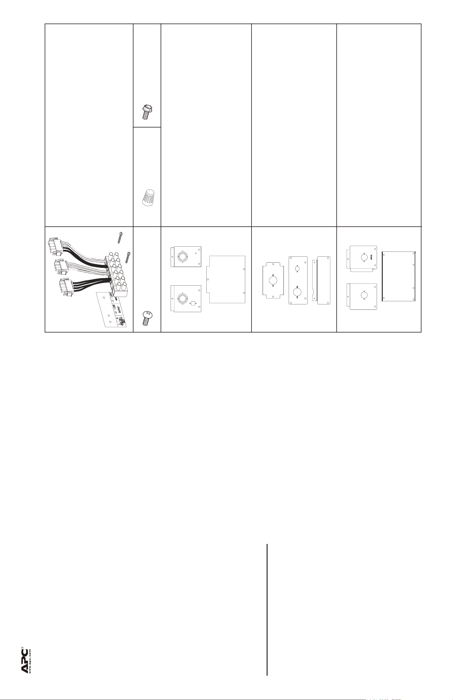
4 grounding screws
2 wire nuts
Package Contents
Model 5000RM5U 208/230 V
Terminal block
Terminal block label
Screws for securing terminal block to UPS
Model 2200/3000 Tower 100/120/230 V
Input and output panels
Blank panel to cover terminal block
Model 2200/3000XL 120/208/230 V
Input panel
Output panel
Blank panel to cover terminal block
Input and output panels
Blank panel to cover terminal block
8 screws for securing
panels to UPS
Installation Guide Smart-UPS I/O Hardwire Kit
be disconnected.
models may have external batteries connected to the UPS. The external batteries must be
disconnected from the UPS.
NOTE: Model 5000RM5U has four internal batteries. The two front batteries must be
disconnected.
1. Disconnect equipment connected to the UPS.
Safety Information - read these instructions before hardwiring the UPS
Wiring must be performed by qualified electrical personnel.
Adhere to all national and local electrical codes when wiring this unit.
2. Press the OFF button located on the front of the UPS.
a. Model 5000RM5U has four internal battery modules. The two front internal batteries must
b. Models 2200/3000XL require the disconnect of one internal battery module. The XL
3. Disconnect batteries from the UPS.
c. All other units require the disconnect of one internal battery module.
4. Disconnect the UPS from utility power.
When removing the panels from the UPS, note which cable is connected to the AC
input. There are two 4-pin connectors on the UPS and they are not interchangeable.
Connect to localized APC Web sites for specific countries, each of which provides
customer support information.
Global support searching APC Knowledge Base and using e-support.
customer support requests.
– www.apc.com (Corporate Headquarters)
• Refer to the APC Web site to access documents in the APC Knowledge Base and to submit
APC Worldwide Customer Support
Customer support for this or any other APC product is available at no charge in any of the following
ways:
– www.apc.com/support/
Local, country-specific centers: go to www.apc.com/support/contact for information.
• Contact an APC Customer Support center by telephone or e-mail.
990-3239A 7/2008
Contact the APC representative or other distributor from whom you purchased your APC product
for information on how to obtain local customer support.
Entire contents copyright 2008 American Power Conversion Corporation. All rights reserved.
Reproduction in whole or in part without permission is prohibited.
APC, the APC logo, and Smart-UPS are trademarks of American Power Conversion Corporation.
All other trademarks, product names, and corporate names are the property of their respective owners and are used for informational purposes only.
Page 2
A
A
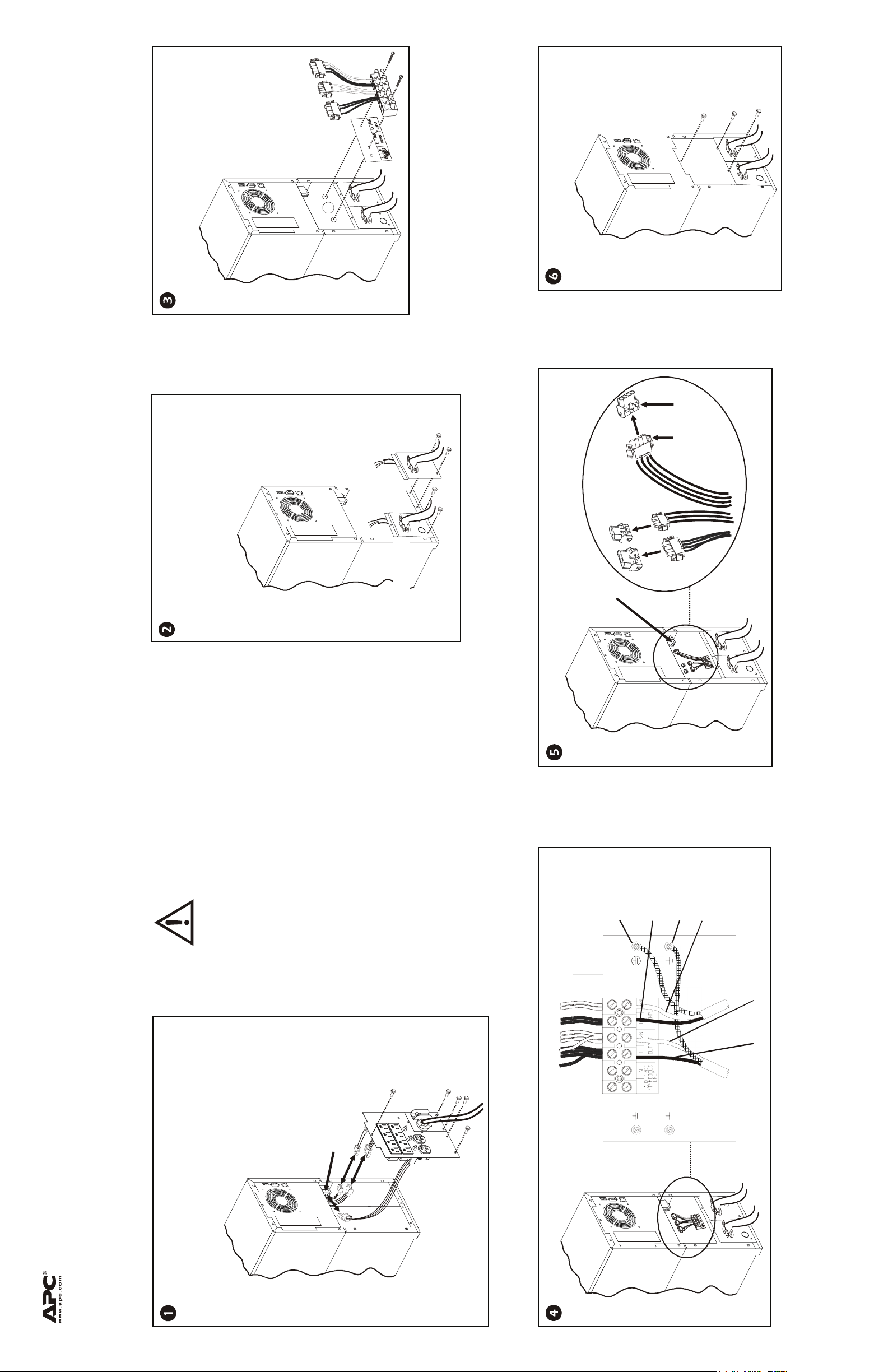
Secure the terminal block and label to the
UPS as shown in the diagram, using
two screws (supplied).
Input panel
Secure the blank panel to the UPS using
three screws (supplied).
C Input
Connectors
Secure the hardwire input and output panels
(supplied), to the UPS using four of the screws
removed from the PDU/IO panels.
Install appropriate strain relief clamps
(not supplied), to the I/O panels as shown in
the diagram.
NOTE: The input and output cables may be
connected to the terminal block prior to
installing the panels and the terminal block
in the UPS.
Output panel
AC Input
Connector
Connect the terminal block and UPS connectors as shown in diagram.
Primary
Ground
(Green Wire)
Input Line1
Ground
Input Line2
(Hot)
(or Neutral)
C Input Connector
Installation Guide Smart-UPS I/O Hardwire Kit
Remove the five screws that secure the PDU/IO panels
to the UPS.
Save these screws for securing the I/O hardwire panels.
Disconnect the PDU/IO cables as shown in the diagram.
Output Line2
(or Neutral)
Output Line1
990-3239A 07/2008
Connect input and output wires as shown in diagram.
2200/3000 Tower 100/120/230 V models
The AC input/output panels on the 2200/3000 VA tower units vary in appearance. The hardwire panels and hardwiring configurations for the 2200/3000 VA tower units are identical.
Page 3

Secure the terminal block and label to the UPS as shown in the
diagram, using two screws (supplied).
Secure the hardwire input panel (supplied), to
the UPS using two of the screws removed from
the PDU panel.
Install appropriate strain relief clamps
Secure the output panel to the UPS using two screws,
(screws and panel supplied).
The top edge of the blank panel fits behind the output panel.
Secure the blank panel to the UPS using four screws supplied.
(not supplied), to the input panel (not supplied),
as shown in the diagram.
AC Input
Connector
NOTE: The input and
output cables may be
connected to the
terminal block prior
to installing the panels
and the terminal block
in the UPS.
Remove the screws that secure the I/O panel to the
UPS.
Save these screws for securing the I/O hardwire
panels.
Disconnect the input cable
AC Input
Connector
Connect the terminal block and UPS connectors as shown in diagram.
Primary
Ground
(Green Wire)
Input Line1
AC Input
Connector
Ground
Input Line2
(Hot)
(or Neutral)
Output Line2
(or Neutral)
Installation Guide Smart-UPS I/O Hardwire Kit
Remove the screws that secure the PDU panel to the UPS.
Save these screws for securing the I/O hardwire panels.
2200/3000XL 120/208/230 V models
The PDU and AC input/output panels on the 2200/3000 VA rack-mount units vary in appearance. The hardwire panels and hardwiring configurations for the 2200/3000 VA rack-mount units are identical.
Disconnect the PDUcables as shown in the diagram.
Output Line1
990-3239A 7/2008
Connect input and output wires as shown in diagram.
Page 4

A
A
Secure the terminal block and label to the UPS as shown in the
diagram, using two screws (supplied).
Secure the blank panel to the UPS using
six screws (supplied).
C Input
Connectors
Input
AC Input
Connectors
Secure the hardwire input and output panels (supplied), to the UPS using the four screws removed
from the PDU/IO panel.
Install appropriate strain relief clamps (not supplied), to the I/O panels (supplied), as shown in the
diagram.
230 V model:
Remove the eight screws that secure the PDU/I
panel to the UPS. Remove the two screws that
secure the terminal block in the chassis.
NOTE: The input and
output cables may be
Ground
Save these screws for securing the IO hardwire
panels.
Disconnect the PDU/IO cables as shown in the
diagram.
connected to the
Wire
terminal block prior
to installing the panels
and the terminal block
in the UPS.
Connect the terminal block and UPS connectors as shown in diagram.
Primary
Ground
(Green Wire)
Input Line1
t
u
p
n
I
AC Input
Connector
Ground
Input Line2
(Hot)
(or Neutral)
Output Line2
(or Neutral)
Output Line1
Ground
Wire
990-3239A 07/2008
C Input
Installation Guide Smart-UPS I/O Hardwire Kit
208 V model:
Remove the six screws that secure the PDU/IO
panel to the UPS.
Save these screws for securing the IO hardwire
panels.
Disconnect the PDU/IO cables as shown in the
5000RM5U 208/230 V models
diagram.
Connector
Connect input and output wires as shown in diagram.
 Loading...