

Page 1
Operation Manual
Smart-UPS™ C
Uninterruptible Power Supply
1000/1500 VA
Tower / Rack-Mount 2U
120 Vac/230 Vac
s
u
1
0
1
2
a
Page 2

Page 3
Important Safety Messages
SAVE THESE INSTRUCTIONS - This manual contains important instructions that should be followed during
installation and maintenance of the UPS and batteries.
Read these instructions carefully and look at the equipment to become familiar with the device before trying to
install, operate, service or maintain it. The following special messages may appear throughout this document or on
the equipment to warn of potential hazards or to call attention to information that clarifies or simplifies a procedure.
The addition of this symbol to either a “Danger” or “Warning” safety label indicates that an electrical
hazard exists which will result in personal injury if the instructions are not followed.
This is the safety alert symbol. It is used to alert you to potential personal injury hazards. Obey all
safety messages that follow this symbol to avoid possible injury or death.
DANGER
DANGER indicates a hazardous situation which, if not avoided, will result in death or serious
injury.
WARNING
WARNING indicates a hazardous situation which, if not avoided, could result in death or serious
injury.
CAUTION
CAUTION indicates a hazardous situation which, if not avoided, could result in minor or moderate
injury.
NOTICE
NOTICE is used to address practices not related to physical injury.
Product Handling Guidelines
<18 kg
<40 lb
18-32 kg
40-70 lb
32-55 kg
70-120 lb
>55 kg
>120 lb
Smart-UPS C 1000/1500 VA 120/230 Vac Tower / Rack-Mount 2U 1
Page 4

Safety and General Information
Inspect the package contents upon receipt.
Notify the carrier and dealer if there is any damage.
• Adhere to all national and local electrical codes.
• All wiring must be performed by a qualified electrician.
• Changes and modifications to this unit not expressly approved by APC by Schneider Electric could
void the warranty.
• This UPS is intended for indoor use only.
• Do not operate this unit in direct sunlight, in contact with fluids, or where there is excessive dust or
humidity.
• Be sure the air vents on the UPS are not blocked. Allow adequate space for proper ventilation.
• For a UPS with a factory installed power cord, connect the UPS power cable directly to a wall outlet. Do not
use surge protectors or extension cords.
• The equipment is heavy. Always practice safe lifting techniques adequate for the weight of the equipment.
Deenergizing safety
The UPS contains internal batteries and may present a shock hazard even when disconnected from the branch
circuit (mains). Before installing or servicing the equipment check that the:
• Input circuit breaker is in the OFF position.
• Internal UPS batteries are removed.
Electrical safety
• Use tools with insulated handles.
• Do not handle any metallic connector before power has been disconnected.
• For models with a hardwired input, the connection to the branch circuit (mains) must be performed by a
qualified electrician.
• 230 V models only: In order to maintain compliance with the EMC directive for products sold in Europe,
output cords attached to the UPS must not exceed 10 meters in length.
• The protective earth conductor for the UPS carries the leakage current from the load devices (computer
equipment). An insulated ground conductor is to be installed as part of the branch circuit that supplies the
UPS. The conductor must have the same size and insulation material as the grounded and ungrounded
branch circuit supply conductors. The conductor will typically be green, with or without a yellow stripe.
• Leakage current for a pluggable, Type A UPS may exceed 3.5 mA when a separate ground terminal is used.
• The UPS input ground conductor must be properly bonded to protective earth at the service panel.
• If the UPS input power is supplied by a separately derived system, the ground conductor must be properly
bonded at the supply transformer or motor generator set.
Smart-UPS C 1000/1500 VA 120/230 Vac Tower / Rack-Mount 2U2
Page 5

Hardwire safety
• Check that all branch circuit (mains) and low voltage (control) circuits are deenergized, and locked out
before installing cables or making connections, whether in the junction box or to the UPS.
• Wiring by a qualified electrician is required.
• Check national and local codes before wiring.
• Strain relief is required for all hardwiring (supplied with select products). Snap in type strain reliefs are
recommended.
• All openings that allow access to UPS hardwire terminals must be covered. Failure to do so may result in
personal injury or equipment damage.
• Select wire size and connectors according to national and local codes.
Battery safety
• Servicing of user replaceable batteries should to be performed or supervised by personnel knowledgeable
about batteries and required precautions.
• The batteries typically last for two to five years. Environmental factors impact battery life. Elevated
ambient temperatures, poor quality utility power, and frequent short duration discharges will shorten battery
life.
• APC by Schneider Electric uses sealed lead acid batteries. Under normal use and handling, there is no
contact with the internal components of the battery. Over charging, over heating or other misuse of batteries
can result in a discharge of battery electrolyte. Released electrolyte is toxic and may be harmful to the skin
and eyes.
• CAUTION: Before installing or replacing the batteries, remove jewelry such as wristwatches and rings.
High short circuit current through conductive materials could cause severe burns.
• CAUTION: Do not dispose of batteries in a fire. The batteries may explode.
• CAUTION: Do not open or mutilate batteries. Released material is harmful to the skin and eyes and may be
toxic.
General information
• The model and serial numbers are located on a small, rear panel label. For some models, an additional label
is located on the chassis under the front bezel.
• Always recycle used batteries.
• Recycle the package materials or save them for reuse.
Radio Frequency warning
WARNING: This is a category C2 UPS product. In a residential environment, this product may cause radio
interference, in which case the user may be required to take additional measures.
Note: This equipment has been tested and found to comply with the limits for a Class A digital device, pursuant to
part 15 of the FCC Rules. These limits are intended to provide reasonable protection against harmful interference
when the equipment is operated in a commercial environment. This equipment generates, uses, and can radiate
radio frequency energy and, if not installed and used in accordance with the instruction manual, may cause harmful
interference to radio communications. Operation of this equipment in a residential area is likely to cause harmful
interference in which case the user will be required to correct the interference at his own expense.
Smart-UPS C 1000/1500 VA 120/230 Vac Tower / Rack-Mount 2U 3
Page 6
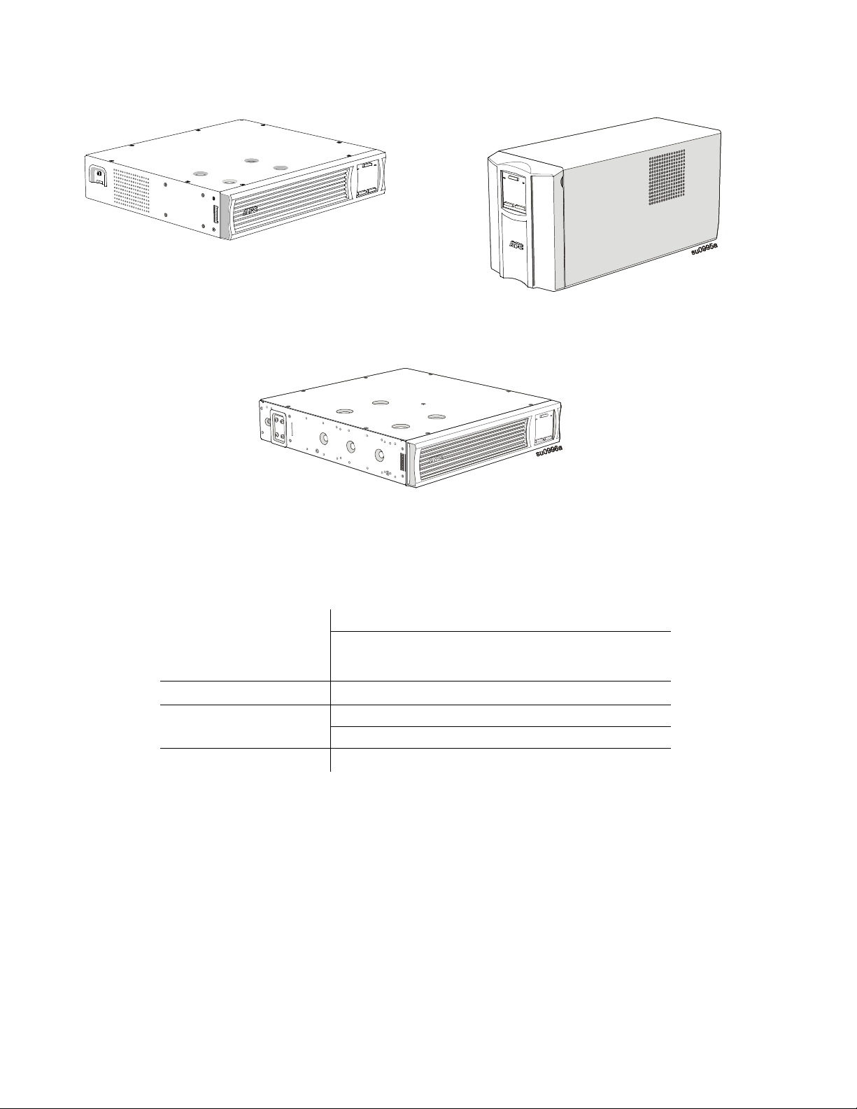
SMC1000-2UC and SMC1000I-2UC Rack-Mount SMC1000C, SMC1000IC, SMC1500C and
SMC1500IC Tower
a
7
9
9
0
u
s
SMC1500-2UC and SMC1500I-2UC Rack-Mount
Specifications
For additional specifications, refer to the APC Web site at www.apc.com.
Environmental specifications
Operating 0° to 40° C (32° to 104° F)
Temperature
IP rating
Maximum Elevation
Humidity
Storage
IP20
Operating 3,000 m (10,000 ft)
Storage
0% to 95% relative humidity, non-condensing
-15° to 45° C (5° to 113° F)
charge UPS battery every six
months
15,000 m (50,000 ft)
Smart-UPS C 1000/1500 VA 120/230 Vac Tower / Rack-Mount 2U4
Page 7
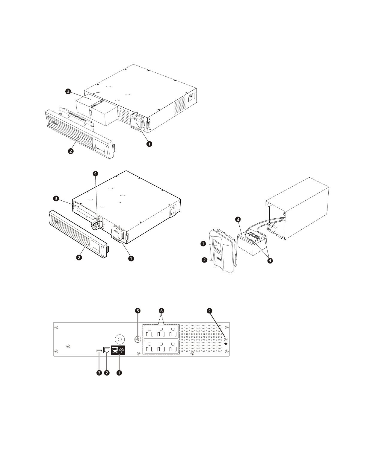
Product Overview
Display (more information below)
Bezel
Battery
Internal battery connector
su0994a
LINK/ACT
NETWORK
Front panel features
=SMC1000-2UC and SMC1000I-2UC Rack-Mount
s
u
0
9
9
3
a
SMC1500-2UC and SMC1500I-2UC Rack-Mount SMC1000C, SMC1000IC, SMC1500C, and
SMC1500ICTower
s
u
0
9
9
2
a
Rear panel features
SMC1000-2UC Rack-Mount
APC™ SmartConnect port
Serial port
USB port
Chassis ground screw
Circuit breaker/overload
protection
su0960a
Outlets
Battery connector
Smart-UPS C 1000/1500 VA 120/230 Vac Tower / Rack-Mount 2U 5
Page 8

SMC1500-2UC Rack-Mount
LINK/ACT
NETWORK
LINK/ACT
NETWORK
su0960b
SMC1000I-2UC Rack-Mount
SMC1500I-2UC Rack-Mount
SMC1000C and
SMC1500C Tower
su0961a
su0959a
SMC1000IC and
SMC1500IC Tower
su0960c
Dimensions and weights
Tower Models Rack-Mount Models
D
H
s
u
0
9
6
5
b
W
su0959b
D
H
s
u
0
9
6
4
b
W
Smart-UPS C 1000/1500 VA 120/230 Vac Tower / Rack-Mount 2U6
Page 9

Model Dimensions (in/mm) H x W x D Weight (lb / kg)
SMC1000C, SMC1000IC
SMC1500C, SMC1500IC 44.3 / 20.1
SMC1000-2UC, SMC1000I-2UC 3.4 x 17 x 16 in (86 x 432 x 409 mm) 39.3 / 17.8
SMC1500-2UC, SMC1500I-2UC 3.4 x 17 x 18.8 in (86 x 432 x 477 mm) 55.8 / 25.3
8.6 x 6.7 x 17.3 in (219 x 171 x 439 mm)
37.5 / 17
Installation
For UPS installation information, refer to the Installation Guide included with the UPS.
The Installation Guide is also available on the Documentation CD included with the UPS and on the APC by
Schneider Electric Web site, www.apc.com.
Placement
The UPS is intended for IT environments. Avoid placement where there is excessive dust, temperature and
humidity. Note that temperature in excess 25
the side or rear of the UPS should be free of obstructions.
The UPS is heavy. For rack-mount units it is suggested that the batteries be removed to facilitate easier installation.
The UPS should be placed near the bottom of the rack.
Connect to equipment and utilities
Note: The UPS will charge to 90% capacity in the first three hours of normal operation.
Do not expect full battery runtime capability during this initial charge period.
o
C may have an adverse effect on battery and UPS life. All vents on
CAUTION
RISK OF DAMAGE TO EQUIPMENT OR PERSONNEL
• Adhere to all local and national electrical codes.
• Wiring should be performed by qualified electrician.
• Always connect the UPS to a grounded outlet.
Failure to follow these instructions can result in injury.
Smart-UPS C 1000/1500 VA 120/230 Vac Tower / Rack-Mount 2U 7
Page 10

1. Connect equipment to the outlets in the rear of the UPS.
LINK/ACT
NETWORK
2. Connect the APC SmartConnect port to your nearest network switch using the cable provided.
3. Connect the UPS input to AC power.
4. Press the main power button on the UPS display to turn on the UPS output.
Note: The On-line LED will light green when the output is on.
5. Log onto www.smartconnect.apc.com or scan the QR code to launch the registration process. The website
includes instructions to setup your online account, activate your warranty and begin managing your UPS
remotely.
su0441c
Note: By connecting this product to the Internet using the APC SmartConnect port, you are agreeing to APC
SmartConnect Terms of Use, as found at smartconnect.apc.com. Schneider Electric Data Privacy Policy can also be
found at smartconnect.apc.com.
Smart-UPS C 1000/1500 VA 120/230 Vac Tower / Rack-Mount 2U8
Page 11

Status Indicators
su0740d
su0740 c
Display panel features
1000/1500 VA 120 Vac 1000/1500 VA 230 Vac
On Line/On Battery LED
POWER ON/OFF button
Site Wiring Fault/System Alert LED
Note: Refer to “Display Menu” section on page 11 in this manual for a detailed description of the front panel
buttons and icons.
Status LED
Power On
The UPS is supplying AC power
to connected equipment.
On Battery
The UPS is supplying battery
power from the internal battery.
System Alert
The UPS detects an internal
system error. Refer to “System
Errors and Message Codes” .
Display icons
120 Vac 230 Vac Description
Display interface
MENU button
MUTE/ENTER button
Audible Indicator
On Audible Indicator Terminates
The On Line/On
Battery LED
illuminates green.
The On Line/On
Battery LED
illuminates amber.
System Error LED
illuminates red.
On Line: The UPS is supplying conditioned AC power to connected equipment.
None N/A
The UPS beeps 4 times
every 30 seconds.
Constant tone (for
severe errors only)
The beeping stops when AC power is
restored or the
pressed for two seconds.
The alarm stops when the
ON/OFF button is pressed for two
seconds. This creates a System
Error Reset.
MUTE button is
POWER
Green mode: The UPS is operating at the most efficient level by bypassing unused
AVR components while acceptable AC voltage is present. The UPS will enter and
exit Green mode automatically and will not compromise power protection.
Load Capacity: The load capacity percentage is indicated by the number of load bar
sections illuminated. Each bar represents 20% of the load capacity.
Estimated Run Time / Min: This indicates the battery runtime minutes that remain
if the UPS switches to battery power.
Battery Charge: The battery charge level is indicated by the number of bar sections
illuminated. When all five blocks are illuminated, the battery is fully charged. Each
bar represents 20% of the battery charge capacity.
Smart-UPS C 1000/1500 VA 120/230 Vac Tower / Rack-Mount 2U 9
Page 12

120 Vac 230 Vac Description
Overload: The equipment connected to the UPS is drawing more power than the
UPS rating allows.
Event: The event counter indicates the number of events that occurred to cause the
UPS to switch to battery operation.
In: Input voltage.
Out: Output voltage.
Load: Output power.
System Error Detected: An internal system error has occurred. The error number
will illuminate on the display. Refer to “System Errors and Message Codes” section
on page 15.
Automatic Voltage Regulation (AVR): The UPS has an AVR boost feature that
automatically compensates for low or high levels of input voltage without using
battery power.
When illuminated, the UPS is compensating for low input voltage.
When illuminated, the UPS is compensating for high input voltage.
Mute: An illuminated line through the icon indicates that the audible alarm is
disabled.
Battery Error Detected: The icon will flash to indicate that the battery is
disconnected.
When the icon remains continuously illuminated the UPS did not pass a Self-Test or
the battery is near the end of its service life and must be replaced. Refer to “System
Errors and Message Codes” section on page 15.
On Battery: The UPS is supplying battery backup power to the connected
equipment.
LCD status indicators
Status LCD Icon Audible Alarms Audible Alarm Terminates
On Battery
The UPS is supplying
battery power to the
connected equipment.
AC Power Overload
An overload condition has
occurred while the UPS is
operating on AC power.
Battery Power Overload
An overload condition has
occurred while the UPS is
operating on battery power.
Low Battery
The UPS is supplying
battery power to the
connected equipment and
the battery is near a total
discharge state.
Battery Error Detected
The UPS is operating on
AC power. The battery does
not provide expected
backup.
Beeps 4 times every 30 seconds. The beeping stops when AC power
Constant tone The alarm stops when nonessential
Constant tone The alarm stops when nonessential
Continuous beeping The beeping stops when AC power
The UPS will beep twice to
indicate the battery is
disconnected.
The UPS will beep continuously
for one minute every five hours to
indicate that the battery must be
replaced.
is restored or the UPS is turned off.
equipment is disconnected from the
outlets or the UPS is turned off
equipment is disconnected from the
outlets or the UPS is turned off.
is restored or the UPS is turned off.
Verify that the battery is securely
connected.
The battery is nearing the end of its
service life and must be replaced.
Smart-UPS C 1000/1500 VA 120/230 Vac Tower / Rack-Mount 2U10
Page 13

Status LCD Icon Audible Alarms Audible Alarm Terminates
System Error Detected
The UPS has experienced
an internal error.
120 Vac models
230 Vac models
N/A Identify the error message on the
display and refer to the table of
codes under “System Errors and
Message Codes” section on
page 15.
Display Menu
The main part of the display will show different parameters of the UPS. Pressing the menu button will toggle
through the various menus programmed for Output Voltage, Runtime, Input Voltage, SmartConnect Status, etc.
Feature Reference Guide
Normal mode
Function Button
Power
Power On
Power Off
Display
Menu Button
Mute
Enable/Disable
Error Reset
Timing
(seconds)
0.2 Off
5 On
0.2 On
2 On
2 Error
UPS
State Description
Press the POWER ON/OFF button to turn the UPS output on. The
UPS will operate on AC power.
If AC power is not available the UPS will operate on battery power.
Press the POWER ON/OFF button to turn the output off using
shutdown delays. To turn the output off immediately press and hold
the POWER ON/OFF button for 5 seconds.
The Menu button will advance the display to the next data item. If
the display is darkened to save energy, pressing the Menu button
will illuminate the display.
Enable or disable the audible alarms. The Mute icon will illuminate
and the UPS will beep once.
After an error has been identified, press the
to remove the visual indication and return to standby status.
Configuration mode
Configuration mode provides the ability to adjust UPS parameters and initiate control actions. To enter
configuration mode hold the M
UTE and MENU buttons together for 2 seconds until the system emits a
POWER ON/OFF button
short beep and the display will flash to indicate the UPS has entered Configuration Mode.
When in Configuration Mode, the MENU button cycles the display through the available options. The M
UTE
button toggles the configuration settings for that option.
Note: When the UPS detects 20 seconds of no activity in Configuration Mode, or when the M
UTE and MENU
buttons are pressed together for 2 seconds until the system emits a short beep, the UPS returns to Normal mode.
Smart-UPS C 1000/1500 VA 120/230 Vac Tower / Rack-Mount 2U 11
Page 14

Function Options Description
0740
0740h
su0740i
su0740j
su0740k
Firmware Upgrade
Self-Test
•UP.0
UP.0 = firmware valid and different
from current running firmware
•UP.1
UP.1 = confirm the firmware update
•UPd
UPd = firmware update in progress
• 0: Default Setting
• 1: Begin Self-Test
This mode only appears when firmware is stored in
memory, and different from the current firmware running.
UP.0 indicates new firmware is available and different
from current firmware, but will not install until instructed
by user.
Pressing MUTE instructs the UPS to install new firmware,
and changes the display to UP.1.
UP.1 indicates system is ready for firmware installation.
Press MENU to install the firmware and exit
Configuration Mode; or press MUTE to revert to UP.0
(canceling firmware installation).
Default setting St.0, indicates that a Self Test has not been
requested
Pressing MUTE requests a Self Test and changes display
to St.1.
Press MENU to begin Self Test and exit Configuration
Mode, or MUTE to revert to St.0 (canceling Self test).
Note: Self tests operate only when the output is on.
Power Quality
• Good
•Fair
• Poor
Select the Sensitivity range depending on the desired
quality of output AC power:
• Pq.3: (Default) Good - If selected, the unit will go on
battery power more often to provide the cleanest power
supply to the connected equipment. Use this setting
when the input power is normally good as it provides
the cleanest power supply to the connected load.
• Pq.2 - Fair should be selected if the unit is operating on
battery too often on the high setting. It makes the unit
less sensitive to disturbances in input power. Use this
setting when the line input has frequent variations.
• Pq.1 - If Poor is selected, the UPS will tolerate more
fluctuations in power and will go on battery power less
often.
The unit ships from the factory at the Good setting.
Smart-UPS C 1000/1500 VA 120/230 Vac Tower / Rack-Mount 2U12
Page 15

Function Options Description
su0740l
su0740m
su0740n
su0740o
• for 120V models: 110 -> 120 -> 127
• for 230V models: 220 -> 230 -> 240
Output Voltage
Setting
LCD Energy Save
Mode
Communication
Protocol
Green Mode Enable
• dP.0 = disable
•dP.1 = enable
• cP.0 = disable
•cP.1 = enable
• 0: Disable
• 1: Enable
Select the output voltage (not available on some models)
dP.1 - Enabled (Default) - When enabled the LCD will
automatically dim after 60 seconds of no activity
dP.0 - Disabled - The display will stay illuminated
indefinitely.
Enables / disables the Modbus communication protocol.
cP.1 (enabled) is the default.
When Green Mode is enabled the UPS is operating at the
most efficient level by bypassing unused AVR
components while acceptable AC voltage is present. The
UPS will enter and exit Green mode automatically while
Enabled.
Enabled is the default.
SmartConnect remote
commands
Battery Replaced
• rc.0: remote control disable
• rc.1: remote control enable
• rb.0: No battery replacement
• rb.1: Battery replaced
When enabled, it allows SmartConnect to send
commands and configuration to the UPS.
rc.0, disabled, is the default.
rb.0 - Did not replace battery (default)
rb.1 - Battery has been replaced
Select rb.1 to indicate that the battery has been replaced,
this will reset the constants for the battery runtime
calibration to the default for a new battery.
Smart-UPS C 1000/1500 VA 120/230 Vac Tower / Rack-Mount 2U 13
Page 16

Function Options Description
SmartConnect
Product Key
Troubleshooting
Problem and Possible Cause Solution
The UPS will not turn on or there is no output.
The unit has not been turned on. Press the ON button once to turn on the UPS.
The UPS is not connected to AC power. Be sure the power cable is securely connected to the unit and to
The input circuit breaker has tripped. Reduce the load on the UPS. Disconnect nonessential equipment
The unit shows very low or no input AC voltage. Check the AC power supply to the UPS by plugging in a table
The battery connector plug is not securely connected. Be sure that all battery connections are secure.
There is an internal UPS error. Do not attempt to use the UPS. Contact the Customer Care
The UPS is operating on battery, while connected to input AC power.
The input circuit breaker has tripped. Reduce the load on the UPS. Disconnect nonessential equipment
There is very high, very low, or distorted input line
voltage.
UPS is emitting intermittent beeps.
The UPS is operating normally. None. The UPS is protecting the connected equipment.
UPS does not provide expected backup time.
The UPS battery is weak due to a recent power outage
or is near the end of its service life.
The UPS is experiencing an overload condition. Check the UPS load display. Unplug unnecessary equipment,
Display interface LEDs flash sequentially.
The UPS has been shut down remotely through
software or an optional accessory card.
The Error LED is illuminated. The UPS displays an error message and emits a constant beeping sound.
Internal UPS error detected. Do not attempt to use the UPS. Contact the Customer Care
The Replace Battery icon is illuminated and the UPS beeps for one minute every five hours.
The battery has a weak charge. Allow the battery to recharge for at least four hours. Then,
The Replace Battery icon is flashing and the UPS beeps for once every 2 seconds.
The replacement battery is not properly connected. Be sure that the battery connector is securely connected.
Displays the 14-character SmartConnect Product Key in 4
parts each time Mute is pressed.
To see the characters, press MENU to toggle through the
groups. The groups are displayed with decimal point
movement to ease knowing which part of the code is
being displayed.
Example: Cod -> 123 -> -> 4.56-> -> 78.9 ->
-> 0.1.2 -> -> 34
the AC power supply.
and reset the circuit breaker.
lamp. If the light is very dim, check the AC voltage.
Center immediately.
and reset the circuit breaker.
Move the UPS to a different outlet on a different circuit. Test the
input voltage with the AC voltage display. If acceptable to the
connected equipment, reduce the UPS sensitivity.
Charge the battery. Batteries require recharging after extended
outages and wear out faster when put into service often or when
operated at elevated temperatures. If the battery is near the end
of its service life, consider replacing the battery even if the
replace battery indicator has not illuminated.
such as printers.
None. The UPS will restart automatically when AC power is
restored.
Center immediately.
perform a self-test. If the problem persists after recharging,
replace the battery.
Smart-UPS C 1000/1500 VA 120/230 Vac Tower / Rack-Mount 2U14
Page 17

Problem and Possible Cause Solution
The UPS displays a site wiring error message (Error code G.00).
Wiring errors detected include missing Ground, HotNeutral polarity reversal, and overloaded Neutral.
Battery lifetimestatus (Error code L.01/L.02) If the LCD indicates battery LifeTime NearEnd or Exceeded,
System Error LED will flash on 2 seconds and flash off 1 second
to indicate site wiring fault. If the UPS indicates a site wiring
error, have a qualified electrician inspect the building wiring.
(Applicable for 120 V units only.)
press the MUTE button for 0.2 second to acknowledge the alarm.
System Errors and Message Codes
P. 00 Output Overload b.00 Battery Disconnected
P. 01 Output Short Circuit b.01 Battery Over Voltage
P. 02 Output Over Voltage b.02 Battery Need Replacement
P. 03 TransformerDCImbalance b.03 Battery OvertemperatureCritical
P. 04 Unit Over Temperature b.04 Battery Charger
P. 05 BackFeedRelay Error b.05 Battery Temperature Sensor
P. 06 AVR Relay Error b.07 Battery Overtemperature Indicator
120 Vac
su0752 c
230 Vac
su0752d
For more information on System Errors, contact customer support at the APC by Schneider Electric Web site,
www.apc.com/support.
P. 08 Output Relay Error b.12 Battery VoltageSensorError
P. 13 Inverter Error
P. 17 Green Relay Error
G. 0 0 SiteWiring G. 0 7
G. 0 1 EEPROM G. 0 8 FirmwareMismatch
G. 0 2 ADConverter G. 0 9 Oscillator
G. 0 3 LogicPowerSupply G. 1 0 MeasurementMismatch
G. 0 4 InternalCommunication G. 11 Subsystem
G. 0 5 UIButton
G. 0 6 NeedsFactorySetup
L.01 LifeTimeNearEnd L.02 LifeTimeExceeded
The See Manual display icon will not appear when the UPS encounters the following
SmartConnect communication states:
Sc.0 SmartConnect No Ethernet Sc.5
Sc.1 SmartConnect Service Connected Sc.6
SmartConnect Addressing
Sc.2
(obtaining local address DHCP)
SmartConnect Resolving
Sc.3
(addressing completed resolving
DNS)
SmartConnect Contracting
Sc.4
(no DNS detection)
EPOActive (reserved for 2200 VA and 3000
VA models only)
SmartConnect Securing
(Transport Layer Security “TLS” being
established)
SmartConnect Connecting
(application link being established with
cloud)
SmartConnect Disabled
(for Embedded systems when a wombat card
Sc.7
is inserted or a configuration has disabled the
LCE)
SmartConnect Prohibited
unit is in factory mode or hardware prevents
Sc.8
operation (EEPROM, MAC or PHY failure
detected)
SmartConnect
APC SmartConnect allows you to monitor the health and status of your UPS from any device connected to the
Internet. Visit www.smartconnect.apc.com to learn more.
Smart-UPS C 1000/1500 VA 120/230 Vac Tower / Rack-Mount 2U 15
Page 18

Battery Replacement
CAUTION
RISK OF HYDROGEN SULPHIDE GAS AND EXCESSIVE SMOKE
• Replace the battery at least every 5 years.
• Replace the battery immediately when the UPS indicates battery replacement is necessary.
• Replace battery at the end of its service life.
• Replace batteries with the same number and type of batteries as originally installed in the equipment.
• Replace the battery immediately when the UPS indicates a battery over-temperature condition, or UPS
internal over-temperature, or when there is evidence of electrolyte leakage. Power off the UPS, unplug
it from the AC input, and disconnect the batteries. Do not operate the UPS until the batteries have been
replaced.
• *Replace all battery modules (including the modules in External Battery Packs) which are older than
one year, when installing additional battery packs or replacing the battery module(s).
Failure to follow these instructions can result in minor or moderate injury and equipment damage.
* Contact Schneider Electric Worldwide Customer Support to determine the age of the installed battery modules.
Always recycle used batteries.
For information on recycling a used battery, refer to the Battery Disposal
Information sheet included with the replacement battery.
Battery life is highly dependent on temperature and use. To identify when to replace batteries, the Smart-UPS
models have a predictive battery replacement date indication and automatic (and configurable) self-tests.
Proactively replace batteries to maintain the highest availability. To ensure protection and high performance, use
only genuine APC replacement battery cartridges (RBC™). The APC RBC contains instructions for battery
replacement and disposal. To order a replacement battery go to the APC by Schneider Electric Web site,
www.apc.com.
UPS Model Replacement Battery Battery Module
SMC1000C, SMC1000IC APCRBC142
SMC1500C, SMC1500IC RBC6
SMC1000-2UC, SMC1000I-2UC APCRBC124
SMC1500-2UC, SMC1500I-2UC APCRBC157
Transport
1. Shut down and disconnect all connected equipment.
2. Disconnect the unit from utility power.
3. Disconnect all internal and external batteries (if applicable).
4. Follow the shipping instructions outlined in the Service section of this manual.
Lead acid, 1 module
Smart-UPS C 1000/1500 VA 120/230 Vac Tower / Rack-Mount 2U16
Page 19

Service
If the unit requires service, do not return it to the dealer. Follow these steps:
1. Review the Troubleshooting section of the manual to eliminate common problems.
2. If the problem persists, contact APC by Schneider Electric Customer Support through the APC Web site,
www.apc.com.
a. Note the model number and serial number and the date of purchase. The model and serial numbers
are located on the rear panel of the unit.
b. Call APC Customer Support and a technician will attempt to solve the problem over the phone. If
this is not possible, the technician will issue a Returned Material Authorization Number (RMA#).
c. If the unit is under warranty, the repairs are free.
d. Service procedures and returns may vary internationally. Refer to the APC Web site for country
specific instructions.
3. Pack the unit properly to avoid damage in transit. Never use foam beads for packaging. Damage sustained
in transit is not covered under warranty.
a. Always DISCONNECT THE UPS BATTERIES before shipping in compliance with U.S.
Department of Transportation (DOT) and IATA regulations. The internal batteries may remain
in the UPS.
4. Write the RMA# provided by Customer Support on the outside of the package.
5. Return the unit by insured, prepaid carrier to the address provided by Customer Support.
Smart-UPS C 1000/1500 VA 120/230 Vac Tower / Rack-Mount 2U 17
Page 20

Limited Factory Warranty
Schneider Electric IT Corporation (SEIT), warrants its products to be free from defects in materials and
workmanship for a period of two (2) years from the date of purchase. The SEIT obligation under this warranty is
limited to repairing or replacing, at its own sole option, any such defective products. Repair or replacement of a
defective product or parts thereof does not extend the original warranty period.
This warranty applies only to the original purchaser who must have properly registered the product within 10 days
of purchase. Products may be registered online at warranty.apc.com.
SEIT shall not be liable under the warranty if its testing and examination disclose that the alleged defect in the
product does not exist or was caused by end user’s or any third person’s misuse, negligence, improper installation,
testing, operation or use of the product contrary to SEIT’s recommendations or specifications. Further, SEIT shall
not be liable for defects resulting from: 1) unauthorized attempts to repair or modify the product, 2) incorrect or
inadequate electrical voltage or connection, 3) inappropriate on site operation conditions, 4) Acts of God, 5)
exposure to the elements, or 6) theft. In no event shall SEIT have any liability under this warranty for any product
where the serial number has been altered, defaced, or removed.
EXCEPT AS SET FORTH ABOVE, THERE ARE NO WARRANTIES, EXPRESS OR IMPLIED, BY
OPERATION OF LAW OR OTHERWISE, APPLICABLE TO PRODUCTS SOLD, SERVICED OR
FURNISHED UNDER THIS AGREEMENT OR IN CONNECTION HEREWITH.
SEIT DISCLAIMS ALL IMPLIED WARRANTIES OF MERCHANTABILITY, SATISFACTION AND
FITNESS FOR A PARTICULAR PURPOSE.
SEIT EXPRESS WARRANTIES WILL NOT BE ENLARGED, DIMINISHED, OR AFFECTED BY AND NO
OBLIGATION OR LIABILITY WILL ARISE OUT OF, SEIT’S RENDERING OF TECHNICAL OR OTHER
ADVICE OR SERVICE IN CONNECTION WITH THE PRODUCTS.
THE FOREGOING WARRANTIES AND REMEDIES ARE EXCLUSIVE AND IN LIEU OF ALL OTHER
WARRANTIES AND REMEDIES. THE WARRANTIES SET FORTH ABOVE CONSTITUTE SEIT’S SOLE
LIABILITY AND PURCHASER’S EXCLUSIVE REMEDY FOR ANY BREACH OF SUCH WARRANTIES.
SEIT WARRANTIES EXTEND ONLY TO ORIGINAL PURCHASER AND ARE NOT EXTENDED TO ANY
THIRD PARTIES.
IN NO EVENT SHALL SEIT, ITS OFFICERS, DIRECTORS, AFFILIATES OR EMPLOYEES BE LIABLE
FOR ANY FORM OF INDIRECT, SPECIAL, CONSEQUENTIAL OR PUNITIVE DAMAGES, ARISING OUT
OF THE USE, SERVICE OR INSTALLATION OF THE PRODUCTS, WHETHER SUCH DAMAGES ARISE
IN CONTRACT OR TORT, IRRESPECTIVE OF FAULT, NEGLIGENCE OR STRICT LIABILITY OR
WHETHER SEIT HAS BEEN ADVISED IN ADVANCE OF THE POSSIBILITY OF SUCH DAMAGES.
SPECIFICALLY, SEIT IS NOT LIABLE FOR ANY COSTS, SUCH AS LOST PROFITS OR REVENUE,
WHETHER DIRECT OR INDIRECT, LOSS OF EQUIPMENT, LOSS OF USE OF EQUIPMENT, LOSS OF
SOFTWARE, LOSS OF DATA, COSTS OF SUBSTITUANTS, CLAIMS BY THIRD PARTIES, OR
OTHERWISE.
NOTHING IN THIS LIMITED WARRANTY SHALL SEEK TO EXCLUDE OR LIMIT SEIT’S LIABILITY
FOR DEATH OR PERSONAL INJURY RESULTING FROM ITS NEGLIGENCE OR ITS FRAUDULENT
MISREPRESENTATION OF TO THE EXTENT THAT IT CANNOT BE EXCLUDED OR LIMITED BY
APPLICABLE LAW.
To obtain service under warranty you must obtain a Returned Material Authorization (RMA) number from
customer support. Customers with warranty claims issues may access the SEIT worldwide customer support
network through the SEIT Web site: www.apc.com
menu. Open the Support tab at the top of the web page to obtain information for customer support in your region.
Products must be returned with transportation charges prepaid and must be accompanied by a brief description of
the problem encountered and proof of date and place of purchase.
. Select your country from the country selection drop down
Smart-UPS C 1000/1500 VA 120/230 Vac Tower / Rack-Mount 2U18
Page 21

Page 22

APC by Schneider Electric
Worldwide Customer Support
Customer support for this or any other APC by Schneider Electric product is available at no charge in any of the
following ways:
• Visit the APC by Schneider Electric web site to access documents in the APC by Schneider Electric
Knowledge Base and to submit customer support requests.
– www.apc.com (Corporate Headquarters)
Connect to localized APC by Schneider Electric web sites for specific countries, each of which
provides customer support information.
– www.apc.com/support/
Global support searching APC by Schneider Electric Knowledge Base and using e-support.
• Contact the APC by Schneider Electric Customer Support Center by telephone or e-mail.
– Local, country specific centers: go to www.apc.com/support/contact for contact information.
– For information on how to obtain local customer support, contact the APC by Schneider Electric
representative or other distributor from whom you purchased your APC by Schneider Electric product.
Select models are ENERGY STAR® qualified.
For more information on your specific model go to www.apc.com.
© 2018 APC by Schneider Electric. APC, the APC logo and APC, the APC logo, Smart-UPS and
SmartConnect are owned by Schneider Electric Industries S.A.S. or their affiliated companies. All other
trademarks are property of their respective owners.
10/2018EN 990-5444C
 Loading...