

Page 1
Operation Manual
Smart-UPS™ C
Uninterruptible Power Supply
Tower
1000/1500 VA
120/230 Vac
su0813a
Page 2
Product Description
The APC™ by Schneider Electric Smart-UPS™ is a high performance unint erruptible power supply ( UPS). The
UPS provides protection for electronic equipm ent from utility power blackouts, brownouts, sags, and surges, small
utility power fluc tuations and lar ge disturbances. The UPS also provides battery backup powe r for conne cted
equipment until utility power returns to safe levels or the batteries are fully discharged.
This user manual is available on the enclosed Documentation CD and on the APC by Schneider Electric Web site,
www.apc.com.
Important Safety Messages
Read the instructions carefully to become familiar with the equipment before trying to install, operate, service or
maintain it. The f ollowing special messages may appear throughout this manual or on the equipment to warn of
potential hazards or to call attention to information that clarifies or simplifies a procedure.
The addition of thi s sym bol to a Caution product sa fety label indicat es that a hazard exists that can
result in injury and product damage if the inst ructions are not followed.
The following safety messages may appear throughout this manual to warn of potential hazards.
CAUTION
CAUTION indicates a potentially hazardous situat ion which, if not avoided, can result in equip m en t dam a ge .
Safety and General Information
Inspect the package contents upon receipt. Notify the carrier and dealer if there is any
damage.
Read the Safety Guide supplied with this unit before installing the UPS.
• Adhere to all local and national electr ical codes.
• This UPS is intended for indoor use only.
• Do not operate this UPS in dire ct sunlight, in cont act with fluids, or where there is excessive dus t or
humidity.
• Be sure the air vents on the UPS are not blocked. Allow adequate space for proper ven tilation.
• The battery typic ally la sts for two to f ive year s. Environ menta l fact ors impac t batte ry life. Eleva ted ambie nt
temperatures, poor quality utility power, and frequent short dura tion discharge s will shorten battery life.
• Connect the UPS power cabl e directly to a wall outlet. Do not use surge prot ectors or extension cords.
• The batteries are he avy. Remove the batteries pr ior to installing the UPS in a rack.
• Refer to “Specifications” on page 2 for UPS and battery weight.
1Smart-UPS C 1000/1500 VA 120/230 Vac Tower
Page 3

Specifications
For additional specific ations, refer to the APC by Schneider Electric Web site at www.apc.com.
UPS + Batte ry Battery
Weight
specifications
Temperature
Maximum
Elevation
Humidity
Battery Type
SMC1000 / SMC1000I
17.24 kg (38 lb)
SMC1500 / SMC1500I
20.41 kg (45 lb)
Operating 0° to 40° C (32° to 104° F)
Storage -15° to 45° C (5° to 113° F)
Operating 3,000 m (10,0 00 ft)
Storage 15, 000 m (50,000 ft)
0% to 95% relati ve humidity,
non-condensing
Mainte n an c e free, sealed le ad acid
Replace used batteries with APC by Schneider Electric approved batte r ies.
To order a replacement batter y go to the APC by Schneider Electric Web site, www.apc.com.
Always recycle used batteries.
For information on recycling a used batter y, refer to the Battery Disposal Information sheet
included with the replacement battery.
APCRBC142
5.1 kg (1 1.2 lb)
APCRBC6
7.7 kg (16.9 lb)
charge UPS battery every six months
0° to 40° C (32° to 104° F)
Smart-UPS C 1000/1500 VA 120/230 Vac Tower2
Page 4
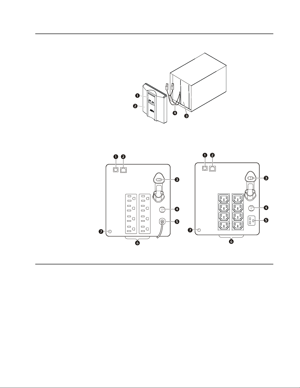
Product Overview
su0325d
su0325e
Front panel features
Display interface
1
Bezel
2
Battery
3
Internal battery connector cables
4
Rear panel features
su0453b
230 Vac
1
USB Port
2
Serial data port
3
Battery connector
4
Circuit br eak er
5
UPS input
6
Outlets
7
Chassis ground scre w
120 Vac
Installation
For UPS installation information, refer to the Installation Guide for the Smart-UPS C 1000/1500 VA
Tower included with the UPS.
The Installati on Guide is also availab le on the Documentation CD incl uded with the UPS and on the
APC by Schneider Electric Web site, www.apc.com.
3Smart-UPS C 1000/1500 VA 120/230 Vac Tower
Page 5
Operation
Note: The UPS will charge to 90% capacity in the first three hours of normal operation.
Do not expect full battery runtime capability during this initial charge period.
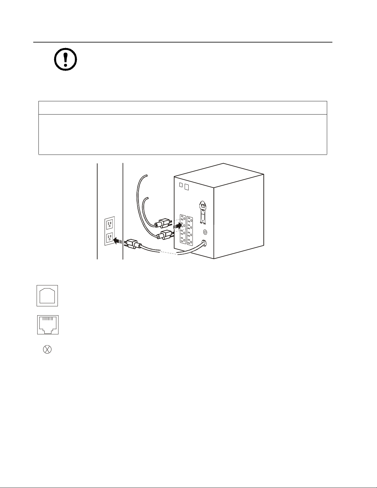
1. Connect equipment to the UPS.
2. Connect the UPS to a two pole, three wire, grounded source.
CAUTION
RISK OF EQUIPMENT DAMAGE
• Adhere to all local and national elect r ical codes.
• Wiring should be performed by qualified electrician.
• Always connect the UPS to a grounde d outlet.
Failure to follow these instructions can result in equipment damage
Connect equipment to the UPS
USB port: Connect to a computer to use power management software.
Serial port: Connect a serial port cable (not supplied) to use power management software.
Chassis ground screw: Connect the ground leads on transient voltage devices to the chassis ground screw(s),
located on the rear panel of the UPS.
su0441b
Smart-UPS C 1000/1500 VA 120/230 Vac Tower4
Page 6

Configuration mode
Configuration mod e provides additional UPS configuration options. Press and hold the MUTE and MENU buttons
for two seconds. The UPS will emit a short beep and the two icons will flash to indicate that
Configuration mod e is ena bled.
When Configuration mode is enabled use the
MENU button to scroll through the available options. Use the MUTE
button to scroll through the settings in each option.
Note: The UPS will automatically disable Configuration mode after 15 seconds of no activity. To
manually disable Configuration mode, press and hold the
The UP S wi l l a emi t a short beep.
MUTE and MENU buttons for two seconds.
Function Options Description
Self-Test
Power Quality
• 0: Def a ul t Se tt in g
• 1: Begin Self-Test
• Good
•Fair
0 is the default setting for Configuration mode. Press the MENU button to scroll
through the available options.
Press 1 to manually initiate a Self-Test. The UPS will automatically disable
Configuration mode.
Note: When the UPS is o per a ti ng on ba t ter y p owe r and Co nfi gur ati o n mo de i s
enabled, only the default setting will be available. A manual Self-Test cannot
be initiated.
Select the input utility power quality tolerance.
• When Good is selected, the unit will go on battery p o we r m ore o ften to
provide the cleanest power supply to the connected equipment.
• When Fair is selected, the UPS is under normal operatin g co ndition s.
Output Voltage
Setting
230V models only
LCD Display
Dimmer
Green Mode
Enable
Clear Event
Counter
• Poor
• 220 Vac
• 230 Vac
• 240 Vac
• Load Bar Icon show s
100% = Always On.
• Load Bar Icon show s 0%
= Auto Dim.
•0: Disable
• 1: Ena b le
N/A
• When Poor is selected, the UPS will tolerate more fluctua tio ns in powe r a nd
will go on battery power less often.
If unsure of the local power quality, select Good.
Select the appropriate voltage for outlets when the UPS is in battery mod e.
When the LCD display dimme r is configu red to Auto Dim the LCD will
illuminate if a button is pressed or an event occurs. The display will
automatically dim after 60 seconds of no activity.
When Green Mode is enabled the UPS is operating at the most efficient level,
bypassing unused AVR components while acceptable utility voltage is present.
The UPS will enter and exit Green mode automatically while enabled.
Press the
MUTE button to clear the event counter.
5Smart-UPS C 1000/1500 VA 120/230 Vac Tower
Page 7

Power sa vi n g L C D scr een
The display interface can be configured to remain continuousl y illuminated or to ext inguish after a period of
inactivity to save electricity.
1. Continuous Illumina tion Mo de: Press and hold the
DISPLAY button for two seconds. Th e display will
illuminate and the UPS will beep to confirm Continuous Illumination mode is activated.
2. Power Saving mode: Press and hold the
DISPLAY button for two se conds . The di splay wil l ex tinguis h and
the UPS will beep to confirm Power Saving mode is enabled. While in Power Saving mode, the display
will illuminate when a button is pressed. The display will extinguish after 60 seconds of inactivity.
Sensitivity adjustment setti ngs
The UPS detects an d rea cts to line voltage distortions by transfer ring to battery b ackup power to protect connected
equipment. In situations where either the UPS or the connected equipment is too sensitive for the input voltage
level it is necessary to adjust the transfer voltage.
1. Connect the UPS to a utilit y power s ource. Be sure the UPS is turned off.
2. Press and hold the
the UP S is in Program mode.
3. Press
the POWER button again to scroll through the menu options. The UPS will beep to confirm the
selection.
When the UPS is in Sensitivity Configuration mode, the Sensitivity bar graph icons display the sensitivity level
setti n g. Se e th e exa m p l es h er e as a ref erence.
Low sensitivi ty Med iu m sensitivi ty High s en s i tivity (De f au lt )
POWER button for six seconds. The load capacity bar will flash on and off, to indicate
1000/1500 VA 120 Vac: 97-136 Vac 1000/1500 VA 120 Vac: 103-130 Vac 1000/1500 VA 120 V ac: 106-127 Vac
1000/1500 VA 230 Vac: 195-265 Vac 1000/1500 VA 230 Vac: 203-257 Vac 1000/1500 VA 230 V ac: 207-253 Vac
Use this setting with equipment
that is less sensitive to fluctuations in
voltage or waveform distortions.
Use this setting under normal operatin g
conditions.
Use this setting when connected
equipment is sensitive to any minor
fluctuations in voltage or waveform
distortions.
Smart-UPS C 1000/1500 VA 120/230 Vac Tower6
Page 8

Status Indicators
su0740d
su0740c
Display panel features
1000/1500 VA 120 V a c 1000/1500 VA 230 Vac
1 On Line/On Battery LED 4 Display interface
POWER ON/OFF button 5 DISPLAY button
2
3 Site Wiring Fault/System Fault LED 6
Note: Refer to “Feature Reference Guide” on page 10 in this manual for a detailed description
of the front panel buttons and icons.
LED status indicators
Status LED
Power On
The UPS is supplying utility power to
connected equipment.
On Battery
The UPS is supplying battery power
from the internal battery.
System Fault
The UPS detects an internal system
fault.
Site Wiring Fault
A building wiring fault has occurred.
Do not operate the UPS. Contact a
qualified electrician to correct the
building wiring fault.
The On Line/On Battery
LED illuminates green
The On Line/On Battery
LED illuminates amber
System Fault LED
illuminates red
Site Wiring Fault
LED flashes red
MUTE button
Audible
Indicator On Audible Indicator Terminates
None N/A
The UPS beeps
4 times ever y 30
seconds.
Constant tone The alarm stops when the
None N/A
The beeping stops when utility power is
restored or the
for two seconds.
FF button is pressed for two seconds.
O
This creates a Fault Reset.
MUTE button is pressed
POWER ON/
7Smart-UPS C 1000/1500 VA 120/230 Vac Tower
Page 9

LCD status in dicators
Status LCD Icon Audible Alarms Audible Alarm Terminates
On Battery
The UPS is supplying battery
power to the connected
equipment.
Utility Power Overload
An overload condition has
occurred while the UPS is
operating on utility power.
Battery Power Overload
An overload condition has
occurred while the UPS is
operating on battery power.
Low Battery
The UPS is supplying battery
power to the connected
equipment and the battery is
near a total discharge state.
Battery Fault
The UPS is operating on utility
power. The battery does not
provi de expected backup.
System Fault
The UPS has experienced an
internal fault.
120 Vac models
Beeps 4 times every 30 seconds. The beeping stops when utility
Constant tone The alarm stops whe n
Constant tone The alarm stops whe n
Continuous beeping The beeping stops when utility
The UPS will beep twice to indicate
the battery is disconnected.
The UPS will beep continuously for
one minute every five hours to
indicate that the battery should be
replaced.
N/A Identify the fault message on
power is restored or the UPS is
turned off.
nonessential equipmen t is
disconnec ted fr om the ou tlet s or
the UPS is turned off
nonessential equipmen t is
disconnec ted fr om the ou tlet s or
the UPS is turned off.
power is restored or the UPS is
turned off.
Verify that the battery is
securely connected.
The battery is nearing the end of
its service life and should be
replaced.
the display and refer to System
Faults in this manual.
230 Vac models
Smart-UPS C 1000/1500 VA 120/230 Vac Tower8
Page 10

Display interface features
1000/1500 VA
120 Vac
1000/1500 VA
230 Vac Description
On Line: The UPS is supplying conditioned utility power to connected
equipment.
Green mode: The U PS i s ope r ating at the mo st e f f ic i ent l e ve l , bypa s sing unused
AVR com ponents while acceptable utility v o ltage is present. The UPS will enter
and exit Green mode automatically and will not compro mise power protection.
Load Cap a c ity: The load ca pacit y perc entage is indica ted by the numb er of lo ad
bar sections illuminated. Each bar represen ts 2 0% of th e loa d capacity.
Estimated Run Time / Min: This indicates the battery runtime minutes that
remain if the UPS switches to battery power.
Battery Charge: The battery charge level is indicated by the number of load bar
sections illuminated. When all five blocks are illuminated, the battery is fully
charged. Each bar represents 20% of the battery charge capacity.
Overload: The equipment c onne ct e d to the U PS is drawing m or e powe r th an the
voltage rating allows.
Event: The event counter indicates the number of events that occurred to cause
the UPS to switch to battery operation.
Automatic Voltage Regulation (AVR): The UPS has an AVR boost and trim
feature that automatically regulates high or low levels of input volta g e w ithout
using battery power. The UPS also features AVR Bypass which temporarily
deactivates the AVR circuitry when the input voltage is within normal range.
This conserves battery power and helps to maximize battery life.
When illuminated, the UPS is compensating fo r low input voltage.
When illuminated, the UPS is compensating fo r high input voltage.
In: Input voltage.
Out: Output voltage.
System Fault: An internal system fault has occurred. The fault number will
illuminate on the display. Refer to “Display interface features” on page 9.
Mute: An illuminated line through the icon indicates th at audible alarms are
disabled.
Battery Fault: The icon will flash to indicate that the battery is disconnected.
When the icon remains continuously illuminated the UPS has failed a
Self-Test or the battery is near the end of its service life and should b e replaced.
Refer to “LCD status indicators” on page 8.
On Battery: The UPS is supplying battery backup power to the connected
equipment.
9Smart-UPS C 1000/1500 VA 120/230 Vac Tower
Page 11

System Faults
1000/1500 120 Vac 1000/1500 230 Vac
su0752a
Note: Refer to the “Feature Reference Gu id e” on page 10 for a detailed description of the front panel buttons and icons.
For more information on System Faults, contact customer support at the APC by Schneider Electric Web site,
www.apc.com/support.
su0752b
P00 Output Overload
P01 Output Short Circuit
P02 Output Over Voltage
P04
Unit Ove r Temperature
P06
AVR Relay Fault
P13
Inverter Fault
Feature Reference Guide
Function Button
Power
Power On
Power Off
Display
Timing
(seconds)
0.2 Off
2On
UPS
Status
Description
Press the POWER ON/OFF button to turn on the UPS.
The UPS will operate on utility power.
If utility power is not available the UPS will operate on battery power.
Press the POWER ON/OFF button to turn off the UPS.
Status Inquiry
Power Saving
mode
Continuous
Illumination
Mute
Event Specific
Enable/Disable
Sensitivity
Self-Test
Event Reset
Fault Reset
0.2 On
2On
0.2 On
2On
6Off
2On
0.2 On
2Fault
Press to verify the status or condition of the UPS. The LCD will
illuminate for 60 seconds.
The LCD will illuminate and the UPS w ill beep to con firm Continuous
Illumination mode is activated.
The LCD will extinguish and the UPS will beep to confirm that
Power Saving mode is activated. While in Po wer Saving mod e, the LCD
will illuminate if a button is pressed or an event occurs, then extinguish
after 60 seconds of no activity.
Disable any audible alarms caused by an event.
Enable or disable the audible alarms. The Mute icon will illuminate and
the UPS will beep once.
The Load Capacity icon will flash to indicate the UPS is in Program
mode. Use the POWER ON/OFF button to scroll through and select Low,
Medium, and High sensitivity levels. The UPS will beep to confirm the
selection. Refer to “Sensitivity adjustment settings” on page 6 in this
manual.
The UPS will automatically run a Self-Test of the internal battery when
the UPS is turned on.
A manual Self-Test can be run at any time while the UPS is operating.
Press and hold the
seconds until the system emits a short beep to indicate the UPS has
started a Self-Test.
When the Event screen is visible, press and hold the DISPLAY button,
then press th e
counter.
After a fault has been identifie d, pre ss the POWER ON/OFF button. The
icon will extinguish and the UPS will go to standby mode.
MUTE button, then press the DISPLAY button for 2
POWER ON/OFF button to clear the utility failure eve n t
Smart-UPS C 1000/1500 VA 120/230 Vac Tower10
Page 12

Troubleshooting
Problem and Possible Cause Solution
The UPS will not turn on or there is no output
The UPS has not been turned on. Press the ON button once to turn on the UPS.
The UPS is not connected to utility power. Be sure the power ca ble is se cure ly c onne cted to the UPS and to the utility power
The input circuit breaker has tripped. Disconnect nonessential equipment and reset the circuit breaker.
The UPS shows very low or no input voltage. Check the utility power supply to the UPS by plugging in a table lamp. If the
The battery is not securely connected. Be sure that all battery connections are secure.
There is an internal UPS fault. Do not attempt to use the UPS. Unplug the UPS and have it serviced
The UPS is operating on battery while connected to utility power
The input circuit breaker has tripped. Disconnect nonessential equipment and reset the circuit breaker.
There is very hi gh, very lo w , or distort ed input
line voltage.
The UPS is beepi ng
supply.
light is very dim, check the utility voltage.
immediately.
Move the UPS to a different outlet on a different circuit. Test the input voltage
with the utility voltage display. If acceptable to the connected equipment, reduce
the UPS sensitivity.
The UPS is operating normally. None. The UPS is protecting the connected equipment.
The UPS does not p rovi de expec ted bat tery backup tim e
The UPS battery is weak due to a
recent power outage or is near the end
of its service life.
The UPS is experiencing an overload
condition.
Charge the battery. Batteries require recharging after an extended outage.
Elevated ambient temperatures, poor quality utility po we r, and frequent short
duration discharges will shorten battery life.
If the battery is near the end of its service life, consider replacing the battery even
if the replace battery icon is not illuminated.
Check the UPS load display. Unplug nonessential equipment, such as printers.
The Fault LED is illuminated, the UPS displays a fault message and emits a constant beeping
Internal UPS fault. Do not attempt to use the UPS. Turn the UPS off and have it serviced
immediately. If more than one fault is present the fault messages will be
displayed alternately on the display screen.
The Replace Battery icon is illuminated
The battery has a weak charge. Allow the battery to recharge for at least four hours. Then, perform a
The replacement battery is n ot
properly connected.
Self-Test. If the problem persists after recharging, replace the battery.
Be sure the battery connector is securely connected.
Site Wiring Fault LE D is flashing
Wiring faults detected include
missing ground, hot-neutral,
polarity reversal, and overloaded
neutral circuit.
If the UPS indicates a site wiring fault, have a qualified electrician inspect the
building wiring. Applicable for 120 Vac units only.
11Smart-UPS C 1000/1500 VA 120/230 Vac Tower
Page 13

Service and Transport
If the unit requires service, do not return it to the dealer. Follow these steps:
1. Review the Troubleshooting section of the manual to eliminate common p r o b lems.
2. If the problem persists, contact APC by Schneider Electric Customer Support through the
APC by Schneider Electric Web site, www. apc.com.
a. Note the model number and serial number and the date of purchase. The model and seri al
numbers are located on the rear panel of the unit and are availabl e through the LCD display
on select models.
b. Cal l APC by Schneider Electric Customer Support and a technician will attempt to solve
the problem over the phone. If this is not possible, the technician will issue a Returne d
Material Authoriza tion Number (RMA#).
c. If the unit is under warranty, the repairs are free.
d. Servic e procedures and returns may vary internationally. Refer to the APC by Schneider
Electric Web site for country specific instructions.
3. Pack the unit in the origi nal packaging whenever pos sible to avoid damage in tr ansit. Never use foam
beads for packaging. Damage sustained in transit is not covered under warranty.
a. Always DISCONNECT THE UPS BATTERIES before shipping. The United St ates
Department of Transportation (DOT), and the International Air Transport
Association (IATA) regulations require that UPS batteries be disconnected before
shipping. The internal batteries may remain in the UPS.
b. Ext ernal Battery Pack products are deenergized when disconnected from the assoc iated
UPS product. It is not necessary to disconnect the internal batterie s fo r shipping. Not all
units utilize an exter nal battery pack.
4. Write th e RMA# provided by Customer Support on the outside of the package.
5. Return the unit by insured, prepaid carrier to the address provided by Customer Support.
Transport the unit
1. Shut down and disconnect all connected equipment.
2. Disconnect the unit fr om uti lity power.
3. Disconn ect all int er nal and external ba tteries ( if ap plicab le).
4. Follow the shipping instructions outlined in the Service section of this manual.
Smart-UPS C 1000/1500 VA 120/230 Vac Tower12
Page 14

Two Year Limited Factory Warranty
This warranty applies onl y to the product s you purchase for your use in accordance with this manu al.
T erms of warranty
Schneider Electric IT (S EIT) warrants its products to be free from defects in material s and workmanship for a peri od of two
years from the date of purc hase. SEIT will repair or rep lace defect ive products cover ed by this warranty. This warranty does not
apply to eq uipment th at has b een damag ed by acci dent , ne glige nce or mi sapp lic ation or ha s be en alt er ed or m odifi ed in any w ay.
Repair or replacement of a defective product or pa rt thereof does not extend the original warranty period. Any parts furnished
under thi s w arranty may be new or factory remanufactured. For cou n try specif ic warranty information, refer to the APC by
Schneider Electric Web site at www.apc.com.
Non-transferable warranty
This warranty extends onl y to the origin al purchaser who must have properly regi stered the product. The product may be
registered at the APC by Schneider Electric Web site, www.apc.com.
Exclusions
SEIT shall not be liable under the warranty if its testing and e xam ination di sclose that the alleged defect in the product does not
exist or was caused by end user’s or any third person’s misu se, neglige nce, improper installation or testing. Further, SEIT shall
not be liable under the warr anty for unauthorized attempts to repair or modify wr ong or inadequate electrical voltage or
connection, inappropriate on site operation conditions, corrosive atmosphere, repair, installation, exposure to the elements, Acts
of God, fire, theft, or installation contrar y to SEIT reco mmendations o r specifications or in any event if the SEIT serial num ber
has been altered, defac ed, or removed, or any other ca use beyond the range of the intended use.
THERE ARE NO WARRANTIES, EXPRESS OR IMPLIED, BY OPERATION OF LAW OR OTHERWISE, OF
PRODUCTS SOLD, SERVICED OR FURNISHED UNDER THIS AGREEMENT OR IN CONNECTION
HEREWITH. SEIT DISCLAIMS ALL IMPLIED W ARRANTIES OF MERCHANTABILITY, SATISFACTION AND
FITNESS FOR A PARTICULAR PURPOSE. SEIT EXPRESS WARRANTIES WILL NOT BE ENLARGED,
DIMINISHED, OR AFFECTED BY AND NO OBLIGATION OR LIABILITY WILL ARISE OUT OF, SEIT
RENDERING OF TECHNICAL OR OTHER ADVICE OR SERVICE IN CONNECTION WITH THE PRODUCTS.
THE FOREGOING W ARRANTIES AND REMEDIES ARE EXCLUSIVE AND IN LIEU OF ALL OTHER
WARRANTIES AND REMEDIES. THE WARRANTIES SET FORTH ABOVE CONSTITUTE SEIT’S SOLE
LIABILITY AND PURCHASER’S EXCLUSIVE REMEDY FOR ANY BREACH OF SUCH WARRANTIES. SEIT
WARRANTIES EXTEND ONL Y TO PURCHASER AND ARE NOT EXTENDED TO ANY THIRD PARTIES.
IN NO EVENT SHALL SEIT, ITS OFFICERS, DIRECTORS, AFFILIATES OR EMPLOYEES BE LIABLE FOR
ANY FORM OF INDIRECT, SPECIAL, CONSEQUENTIAL OR PUNITIVE DAMAGES, ARISING OUT OF THE
USE, SERVICE OR INSTALLA TION, OF THE PRODUCTS, WHETHER SUCH DAMAGES ARISE IN CONTRACT
OR TORT, IRRESPECTIVE OF FAULT, NEGLIGENCE OR STRICT LIABILITY OR WHETHER SEIT HAS BEEN
ADVISED IN ADVANCE OF THE POSSIBILITY OF SUCH DAMAGES. SPECIFICALLY, SEIT IS NOT LIABLE
FOR ANY COSTS, SUCH AS LOST PROFITS OR REVENUE, LOSS OF EQUIPMENT, LOSS OF USE OF
EQUIPMENT , LOSS OF SOFTWARE, LOSS OF DATA , COSTS OF SUBSTITUENTS, CLAIMS BY THIRD
P ARTIES, OR OTHERWISE.
NO SALESMAN, EMPLOYEE OR AGENT OF SEIT IS AUTHORIZED TO ADD TO OR VARY THE TERMS OF
THIS WARRANTY. WARRANTY TERMS MAY BE MODIFIED, IF AT ALL, ONLY IN WRITING SIGNED BY AN
SEIT OFFICER AND LEGAL DEPARTMENT.
Warranty claims
Customers w ith warranty claims issues m ay access the SEI T customer support network through th e Support page of the APC by
Schneid er Elec tric Web site, www. apc.com/support. Select your countr y fr om the cou ntry sel ec tion dr op down menu at the top
of the Web page. Select the Support tab to obtain contact information for customer support in your region.
13Smart-UPS C 1000/1500 VA 120/230 Vac Tower
Page 15

APC by Schneider Electric
Worldwide Customer Support
Customer support for this or any othe r APC by Schneider Electric product is availabl e at no char ge in any of
the following ways:
• V isit the APC by Schneider Electric Web site to access documents in the APC by Schneider Electric
Knowledge Base and to submit customer suppor t reque sts.
– www.apc.com (Corporate Headquarters)
Connect to localized APC by Schneider Electric Web sites for specific countries, each of which
provides customer support information.
– www.apc.com/support/
Global support searchi ng APC by Schneider Electric Knowledge Base and using e-support.
• Contact the APC by Schneider Electri c Customer Support Center by telephone or e-mail.
– Local, country-specific centers: go to www.apc.com/support/contact for contact information.
– For information on how to obtain local customer support, contact the APC by Schneider Electric
representative or other distributors from whom you purchased your APC by Schneider Electric
product.
Select models are ENERGY STAR® qualified.
For more information go to www.apc.com/site/recycle/index.cfm/ener gy-efficiency/energy-s tar/
© 2013 APC by Schneider Electric. APC, the APC logo, Smart-UPS and PowerChute are owned by
Schneider Elect ric Industries S. A.S. or their affiliated companie s. All other tradem arks are property of their
respective owner s.
03/2013EN 990-4493B
 Loading...