

Page 1
Operation Manual
Universal Transfer Switch
UTS6
UTS6H
UTS6BI
UTS10BI
bu154a
UTS10BI
Page 2
Introduction
bu154a
About this product
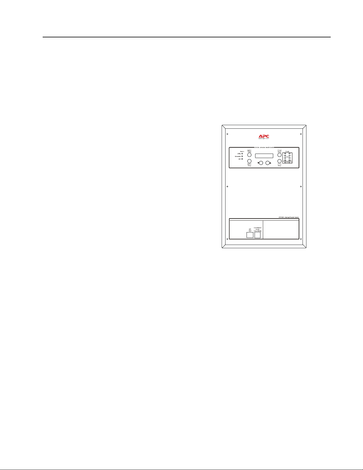
The APC® by Schnei d er El ec tr i c Universal Transfer Switch (UTS) is a fully automatic transfer switch for use in optional
standby syst ems in homes or s mall bus ines ses. This unit prov ide s safe, conveni ent powe r for up to ten circuit s in th e home
or office. Power is derived from one or two independe nt bac kup sources. Backup sourc es being a generator , an
uninterruptible power supply (UPS), a solar inverter, or another alternative energy source.
When connected to home appliances, computers, or entertainment equipment the backup power sources provide power
during uti lity powe r out ages. Whe n a UPS is us ed in t he conf igura tion, connec ted eq uipmen t (load) , c an be pro tected fro m
utility br ownouts, sags, surges, and power outages. The UPS provides continuous power from the internal batter y until
utility power ret urns to safe levels or the batter y is fully discharged .
The models supported by thi s manual vary in appearance and have
some variation in function.
Individual model f unctionality will be addressed in this manual.
UTS10BI
Protect your investment
Fill out the Warranty Registration Card found in th e documentation package, or register your purchas e online at
www.apc.com:
• This will guarantee that the owner receive all of the information and special offers qualified for as the owner
of this product.
• This will confirm the owners right to maximum protection under the Warranty terms and conditions.
• This will confirm yourself as the owner of the product in the event of fire, theft or los s.
1 Operation Manual Universal Transfer Sw it ch UTS6 UTS6H UTS6BI UTS10BI
Page 3

Safety and Regulatory Information - save this information
Read the Operation Manual before operating the UTS.
Read, understand, and follow the Safety Precautions in this manual.
Safety Precautions
• Adhere to all national and local electrical codes when installing, configuring and operating the UTS.
• Installation of the UTS must be performed by a qualified electrician.
• Prior to installing the UTS have a qualified electrician check that the wiring in the home or office meets all
local and national electrical cod es.
• This unit must be conne cte d to a properly grounded utility power source.
• Do not install or operate this unit near a source of water or in an environment where the rel ative humidity
could exceed 95% (non-condensing).
• DO NOT operate a generator inside a building. Operating a generator inside a building ca n cau se death by
asphyxiation.
• DO NOT allow the tot al lo ad conne cte d to the UTS to exceed the limits list ed in the Specifications sectio n of
the Site Preparation and Ins tallation Guide.
• There are no user serv iceable components in this unit. Removing the cover from this unit by unqualified
persons can prese nt a shock hazard and may void the warranty.
• Periodically i n spect all po w er cords to en sure:
– secure co n n ect i on s
– proper routing to ensure cords are not pinched, frayed, or stepped on
• If the UTS is damaged, disconnect the main circuit breaker and contact APC at www.apc.com.
Warning: Stop using the unit immediately i f any of the following conditions arise.
•Conduit or receptacles have been damaged
•Objects have fallen into the unit
•Liquid has spilled into the unit
•The unit has been exposed to rain
•The unit has been dropped or damaged in any way
•The unit does not operate properly
Contact APC at www.apc.com, to arrange service for the unit.
Operation Manual Universal Transfer Switch UTS6 UTS6H UTS6BI UTS10BI2
Page 4

UTS Configurable Features
Feature Description
Uninterruptible Power
Supply
Adaptive Load
Management (ALM)
Load Transfer
Time Management &
Load Shedding
Voltage Sensitivity
Security Mode
also refer red t o a s
vacation mode
• provides UPS backup for uninterrupted operation
• provides backup power until the generator comes on line
Provides automatic shut off (referred to as load shedding), of se lect circuits during blackout
conditions
• prevents power surg es and ove rload conditions from st alling a generator, or tripping circuits
• increases generator ef ficiency by 20% or more during prolonge d power outages
• automatically reconnects loads once the overload conditions have been corrected
Provides automatic transfer of select loads between a generator and a UPS
• minimizing power interruptions due to overload conditions
• maximizing power availability
Time management feature sets maximum and minimum times for ALM to run
Refer to the Configuration and Setup section in this manual for detailed functionality
Settings determine how the UTS reacts to momentary power fluctuations
MEDIUM - factory default
LOW - useful when frequent, small power fluctuations DO NOT require UTS intervention
HIGH - recommended ONLY for loads that are very sensitive to small, brief power
fluctuations
When security mode is set to ON, the UTS automatically cycles power to circuits at a rate of
two hours on and two hours off
Recommended for use on strategic light circuits during vacations
Bypass Mode
Liquid Crystal Display
(LCD)
Automatic Start/Stop
Operation
During bypass mode operation all circuits utilize utility power ONLY
• Backup power sources are not utilized regardless of the quality or condition of utility power
• Overload protection re mains available during bypa ss mode operation
• During initia l setup and configura tion the LCD displays the particula r se tting or value t hat is
to be entered or changed
• During regular operation the LCD is used with various LED indica tors and push buttons
providing UTS status messages, warnings
• During regular operat ion the LCD is used with various LED indicators and push buttons to
perform required actions
Semiautomat ic operation: The UTS automatically switches to generator power once the
generator has been co nnec ted and turned on.
Fully automatic, compatib l e, r emote cont r ol l ed , au t o s t op/start ge n e ra to r s r eq u ir e :
• APC UTS Generator Hardwiring Interface Kit
• APC UTS Automatic Remote Start/Stop Kit
For ordering details contact APC through the Web site, www.apc.com.
3 Operation Manual Universal Transfer Sw it ch UTS6 UTS6H UTS6BI UTS10BI
Page 5
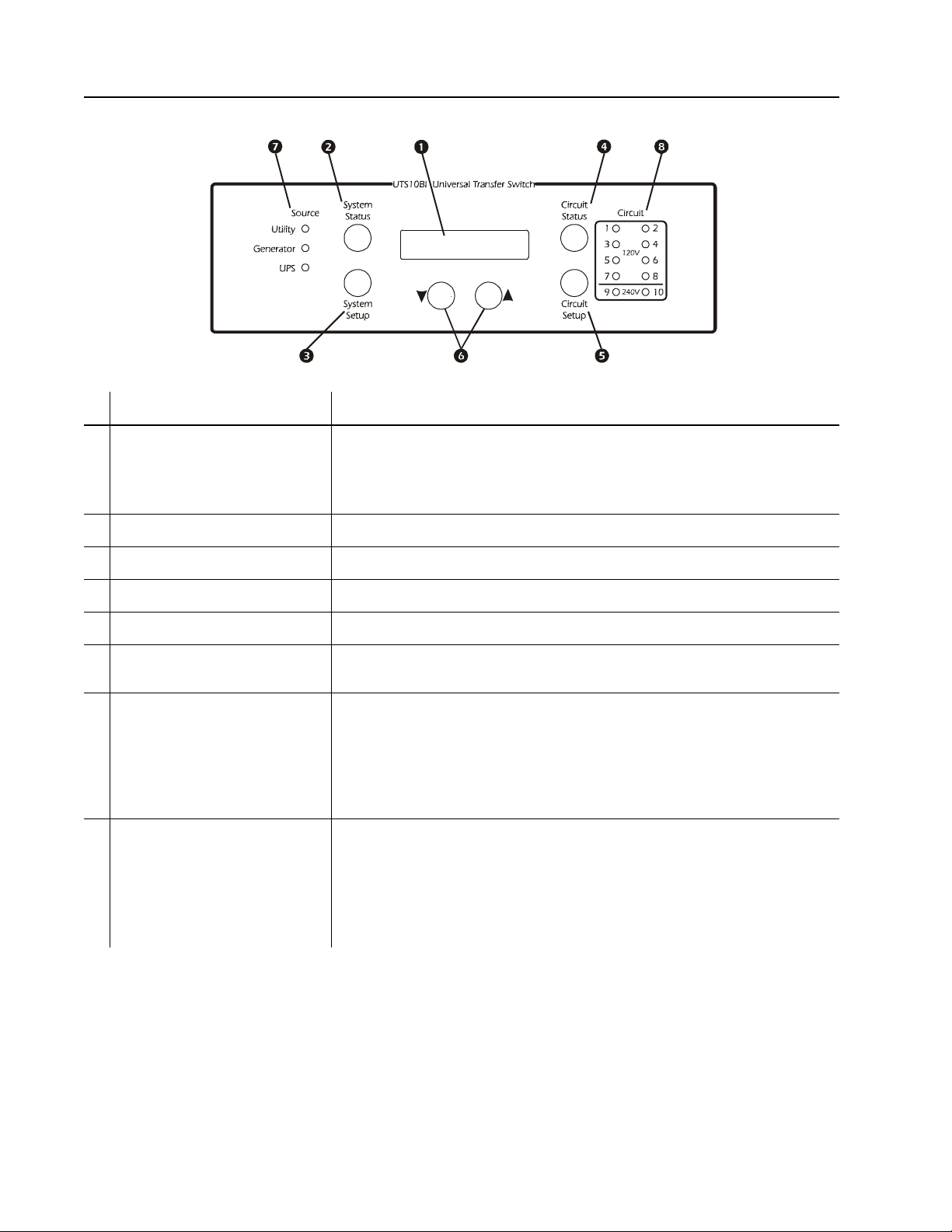
UTS Controls and Indicators
The UTS controls and ind icators are located on the front of the UTS.
bu163a
Control or In dicator Descript i on
LCD • Displays two lines with 20 characters per line
• Displays UTS status, warnings, general info rmation
• Displays the value or setting that is being entered or changed during
configuration and setup
System Status button Cycles the UTS through the default or select ed s ystem status options
System Set up button Used to configure the UTS sys tem options
Circuit Status butto n Cycles the UTS through the circuits displaying the status of each on the LCD
Circuit Setup button Used to configure the UTS individual circui t options
Down/Up arrow buttons Used to scroll through steps for configuration and to scroll between status and
informational displays
Source LEDs
Utility
Generator
UPS
• Solid green LED illum ination indicates that the power source is ON and is
functioning normally
• No LED illumination indicates that the power source is OFF or is outside
specif i ed limits
• A flashing gre en LED indicates that a fault condition exists f o r that power
source, and should be correc ted
Circuit LEDs The number of circuit LEDs varies dependent on the model of UTS
• Red LED illumination indicates that the UTS circuit is receiving power from
one of the power sources
• No illumination indicates that circuit is receiving no power
• A flashing red LED indic ates that a fault condition exists and sho uld be
corrected
Operation Manual Universal Transfer Switch UTS6 UTS6H UTS6BI UTS10BI4
Page 6
UTS circuit LED configurations
120 V
1
3
5
120 V
240 V
1
3
5
120 V
240 V
1
3
5
7
9
bu164a
UTS6/UTS6H
Circuit
2
4
6
120 V circuits ONLY
Together , circuits 5 and 6 form a dedicated
UTS6BI
Circuit
240 V circuit. DO NOT use these circuits as
individual 120 V circuits.
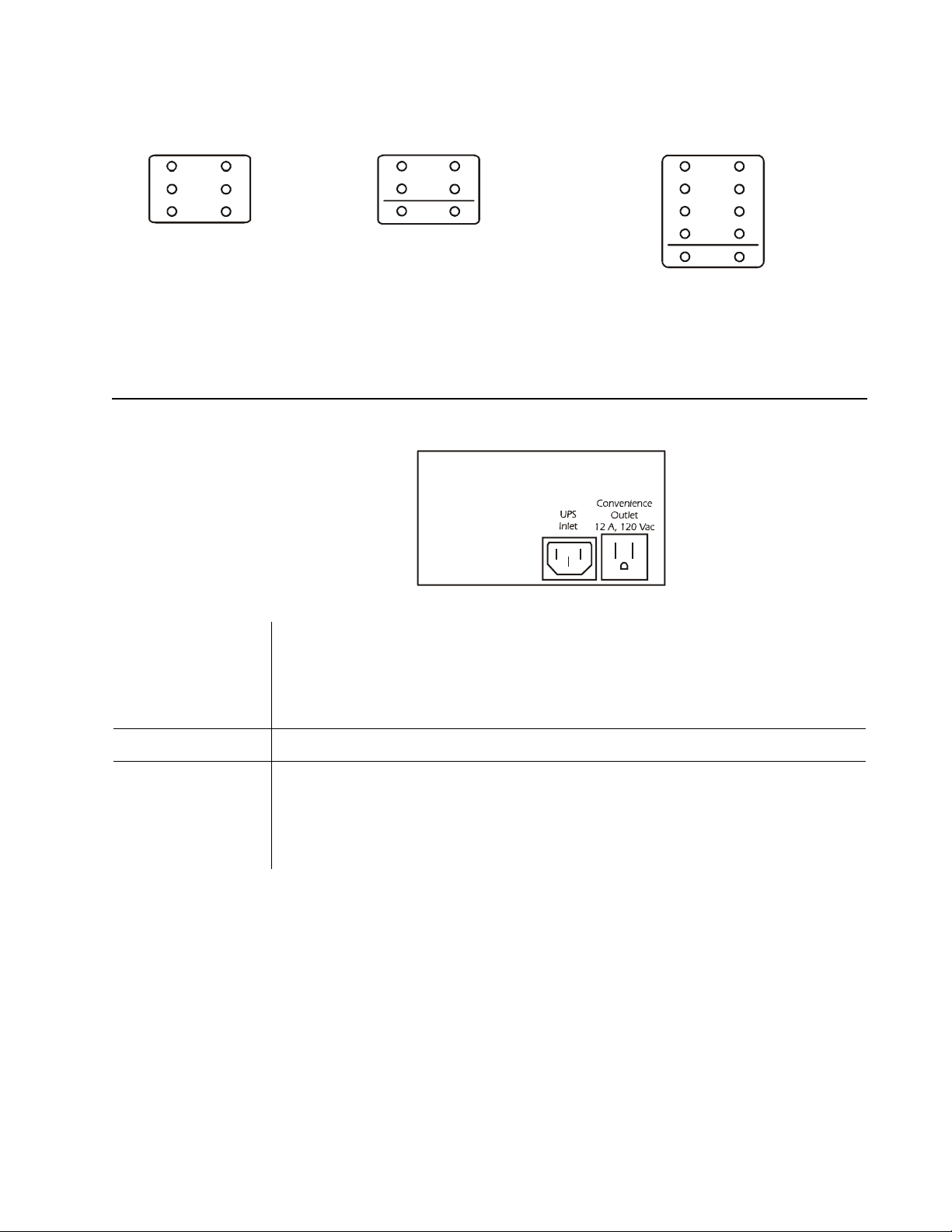
UTS Power Connectors
The power connectors are located on the front of the UTS.
UTS10BI
UTS10BI
Circuit
2
4
6
2
4
6
8
10
Together, circuits 9 and 10 form a dedicated
240 V circuit. DO NOT use these circuits as
individual 120 V circuits.
• Generator inlet is hardwired. Conn ection must be in a remote, out door location. Refer to the
Connect UTS to Backup Power Sources section in the Site Preparation and Installation
Generator Inle t
Guide.
• Refer to the Site Prepa r ation and Install ation Guide for specifica tions concerning th e
generator power cable.
UPS Inlet IEC 320 connector for UPS power cable.
• NEMA 5-15, 120 V convenience outlet for connecting a UPS or another selected load.
• Convenience outlet utilizes utility power or generator powe r.
Convenience Out l et
• If any circuits are to be configured as uninterruptible, a UPS must be used as the Backup2
power source. The UPS input cord should plug into the convenience outlet to all ow the UPS
battery to charge while operating on generator power.
5 Operation Manual Universal Transfer Sw it ch UTS6 UTS6H UTS6BI UTS10BI
Page 7

System Status Verification
UTILITY PHASE1: 120V
UTILITY PHASE2: 120V
SYSTEM LOAD: 2400W
PH1: 1050W PH2: 1350W
GEN PHASE1: 117V
GEN PHASE2: 118V
GEN PHASE1: 480W
GEN PHASE2: 750W
UPS VOLTAGE: 120V
UPS POWER: 200W
MODEL#: UTS10BI
SN#: JB06008004272
UTS FW VER: 1
UI FW VER: 1
MFG DATE: xx/xx/xxxx
The UTS system status and th e status of up to three power sources can be viewed by pressing the System Status button
located on the front of the UTS. To navigate through the system status menus, press the System Status button after
viewing the information on the LCD.
LCD displays the input voltages from the UTILITY through the main
load center for PHASE1 and PHASE2.
LCD displays the SYSTEM LOAD (total power), that is bei ng drawn through the
UTS AND the power drawn by each phase - PH1 and PH2
This informati on provides verification that the phases are bal anced.
LCD displays the BACKUP1 source vol tages for GEN PHASE1 and GEN PHASE2.
The UTS6H is intended for use with a single phase, 120 V generator. GEN PHASE1
and GEN P HASE2 will display identical voltage measurements.
LCD displays the BACKUP1 source power outputs for GEN PHASE1
and GEN PHASE2.
For power measurements: phase1 will display the power outputs of circuits 1, 3, 5.
Phase2 will display power outputs for circuits 2, 4, 6.
LCD displays the UPS VOLTAGE and UPS LOAD for the BACKUP2
source (normally a UPS).
LCD displays the MODEL# (model number), and SN# (serial number)
of the UTS.
LCD displays the FW VER (fi r mw are ver sio n ) in s talled in th e UTS.
LCD displays the MFG DATE (date of manufacture) for the UTS.
Operation Manual Universal Transfer Switch UTS6 UTS6H UTS6BI UTS10BI6
Page 8

System Configuration and Setup
BYPASS LOAD..
NO
LOAD SHEDDING ON/OFF:
ON
VOLTAGE SENSITIVITY :
MEDIUM
Once the UTS has been installed and connected to utility power by a qualifie d electrician, the UTS is rea dy for
configuration and setup.
System setup
Press the System Setup button located on the front of the UTS to enter system setup mode and to navigate through the
system setup options.
Use the down/u p arrow buttons to navigate through the configuration options and to change values displayed on the LCD.
Note: The settings and values sel ec ted will change immediately after an arrow button is pressed.
The LCD will revert back to the starting display message after 30 seconds with no activity.
Bypass Mode
Use the up arrow key to select NO, indicating that bypass mode is disabled or YES,
enabling bypass mode on the UTS.
In bypass mode, all circuits are powered by the utility power source. Backup power
sources are not used to power loads regardles s of the status or quality of the primary
utility power source.
Warning: Changing bypass mode settings while connected to utility power will cause all connected
loads to be momentarily disconnected.
When bypass mode is enabled, overload prote ction is provided. Hig h and low voltage protect ion is not
available when bypass mode is enabled.
Load Shedding
Use the down/up ar row ke ys to se lect ON, indica ting th at load s hedding is enabl ed o r
OFF, to disable load sh edding.
The UTS provides inte lligent load manag ement, defined by APC as adaptive load
management (ALM).
When a backup power source is nearing an overload condition, ALM intelligence sheds (drops) select loads and then
reconnects the loads when adequate power becomes available. ALM selects the most suitable loads to drop and reconnect
at any given time minimizing overall load disruption, and maximizing backup power capability.
When load shedding is enabl ed (ALM is on), the average en ergy output of a backup power source can increase by 20% or
more. This allows more loads to be connected without overloading or stalling a backup power source.
When load shedding is disabled (ALM is off), overload co nditions can occur causing a gene rator to stall, a circuit breaker
to trip, or loads may experience severe low vol tage conditions.
Load Shedding must be enabled for each circuit to be set individually for specific maximum time off and minimum tim e
on. Refer to Circuit Maximum Time Off and Minimum Time On section in this manual.
Voltage Se nsit ivity
Use the down/up arrow keys to select High, Medium, o r Low voltage sensitivity.
The voltage sen si tivity level determines how the UTS reacts to voltage fluctuations.
Medium voltage sensitivity setting is a suitable setting for most situat ion s.
High voltage sensitivity setting is rec ommended only for loads tha t are very sensitive to vol tage fluctuations .
Low voltage sensitivity setting is recommended for loads that can tolerate most power fluctuations.
7 Operation Manual Universal Transfer Sw it ch UTS6 UTS6H UTS6BI UTS10BI
Page 9

Time Management
TIME MANAGEMENT:
ON
RESET ENERGY METER:
NO
SYSTEM TEST:
NO
BACKUP1 SOURCE TYPE:
GENERATOR
GEN POWER RATING:
0-12000 WATTS
GEN SRGE OVRLD TIME:
0-600 SEC
Use the up arrow key to selec t On indicatin g that ti me manag ement is enable d or Off
to disable time management.
Time manage me nt is used with load shedding to ensure loads receive ad equate
power over extended periods of time.
Time Management must be enabl ed for each circuit to be set individually for specific maximum time off and minimum
time on. Refer to Circuit Maximum Time Off and Minimum Time On section in this manual.
Reset Energy Meter
This feature al lows the user to reset to zero, the total number of kilowatt hours used
collec tivel y by the ci rcui ts con nec ted to th e UTS . Refe r to Circuit Configuration and
Setup in this man u al .
Syst em Test
Setting the System Test t o YES initiates a system self-test to che ck UTS operation.
Use the down/up arrow keys to initiate a system self-test.
System Test does not function when the UTS is set up for a manual start generator.
Refer to Generator Star t Mode in this manual for details .
Backup1 Source Ty pe
The factory defaul t se tting is GENERATOR. The generator inlet located on the
front of the UTS provides connectivity for a backup power s ource. The system s etup
has three options for bac kup power:
• Generator
• UPS
Use the down/up arrow keys to sele ct the preferred backup power source. Use the down/up arrow keys to select the
preferred backup power source. APC recommends the use of a generator for BACKUP1.
• Other
Backup1 (Generator) Power Rating
Use the down/up arrow keys to set the correct power rating for the backup power
source connect ed to the UTS.
There are three leve ls for rapi d rating increment changes. Press and hol d the down or
up arrow key to adjust the power rating and to move through the three levels
described here. To revert back to level 1 release the down arrow key then press and hol d the down arrow key.
Level 1 increases or decreases the rating by 5 Watts.
Level 2 increases or decreases the rating by 10 Watts.
Level 3 increases or decreases the rating by 100 Watts.
Generator Surge Overload Time
Use the down/up arrow keys to set the desired ALM response time.
When power output exceeds the pre-s et power rating for the Backup1 Source (see
Genera tor Power Rating above), this feature determines the time it will take for
ALM to respond and activate load shedding process .
Low generator surge overload time settings decrease the possibility of a generator overload condition while increasing
the possibility that ALM will acti vate load shedding.
High generator surg e overload time settings inc rease the possibility of a generator overl oad c ondition while decreasing
the possibility the ALM will activate load shedding.
Inverter generator s must be set at 0 seconds.
Operation Manual Universal Transfer Switch UTS6 UTS6H UTS6BI UTS10BI8
Page 10

Generator Star t Mode
GEN START MODE:
MANUAL
CONFIRM GEN OUTDOORS:
NO
GEN EXHAUST CAN KILL
START GEN OUTDOORS..
BACKUP2 SOURCE TYPE:
UPS
For generators feat uring manual start, use the MANUAL setting. Press the down or
up arrow key to change to AUTO setting.
A warning message appears on the LCD. Wait a few seconds and another message
appears on the LCD asking for confirmation that th e generator is located outdoors.
Use the down or up arrow keys to select YES or NO.
A UTS Hardwire Interface Kit for connecting the generator outside the house is
available through your dealer or APC, www.apc.com.
WARNING: Home generator backup systems should be installed by a qualified electrician.
Locate the generator outside a building and at least 10 feet away from buildings, wind ows, and doors.
Failure to fol low this safety rule may result in illness or death from breath ing carbon monoxide.
The generator must have three to four feet of space around all sides and the top to ensure proper
ventilation.
Locate the generator on a dry, level sur face protected fr om rai n and excess ive dust.
Fuel for gas operated generators must be stored in approved containers, and in well ventilated
conditions.
Refer to the generator user documentation for additional safety precautions.
For generators featuring automatic st art, use the AUTO settin g.
The UTS has a remote automatic start/stop function for use with gene rators having the following features:
• automatic start
• automatic choke
• remote start/stop capability
Refer to the documentation in the Generator Automatic Start/Stop Kit for automatic generator configuration
instructions.
Backup2 Source Ty pe
The factory defaul t setting is UPS. The backup2 power source inlet, located on the
front of the UTS is labele d UPS Inle t as a UPS is the preferred backup2 power
source.
The system setup has three options for backup power:
• Generator
• UPS (recommended BACKUP2 power source)
• Other
Use the down/up arrow keys to sele ct the preferred backup power source .
NOTE: It is recommended that a UPS be used as BACKUP2 SOURCE TYPE. A UPS provides continuous
battery backup power during utility brownouts, sags, surges, and power outages.
Without the use of a UPS, fully automatic operation of the UTS cannot be guaranteed.
If a UPS is not selected for the BACKUP2 power source be sure that the UNINTERRUPTIBLE option under
Circuit Setu p Option 2 is not selected.
9 Operation Manual Universal Transfer Sw it ch UTS6 UTS6H UTS6BI UTS10BI
Page 11

UPS Power Rating
UPS POWER RA TING:
0-1800 WATTS
UPS SRGE OVRLD TIME:
0-60 SEC
RESET TO DEFAULT:
NO
CK1SRC: UTILITY AMP: 1
KWH: 2:35 WATTS: 120
Once the BACKUP2 SOURCE TYPE has been selected, that source type will
appear in the power rating display message. Use the down/up arrow keys to set the
correct power rating for the ba ckup2 power source connected to the UTS.
There are three leve ls for rapi d rating increment changes. Press and hol d the down or
up arrow key to adjust the power rating and to move through the three levels described here. To revert back to level 1
release the down arrow key then press and hold the down arrow key.
Level 1 increases or decreases the rating by 5 Watts.
Level 2 increases or decreases the rating by 10 Watts.
Level 3 increases or decreases the rating by 100 Watts.
UPS Surge Overload Time
Once the BACKUP2 SOURCE TYPE has been selected, that source type will
appear in the surge overload time dis play message. Use the down/up arrow keys to
set the desired ALM response time.
When power output exceeds the pre-s et power rating for the Backup21 Source (see
UPS Power Rating above), this feat ure determines the time it will take for ALM to resp ond and activate load shedding
process.
Low UPS surge overload time settings decr ease the possibility of a generator overlo ad co ndition while increasing the
possib ility th at ALM w il l activat e lo a d s h ed d ing.
High UPS surge overload time settings incr ease the possibility of a generator overlo ad condition while decreasing the
possibility the ALM will activate load shedding.
Reset to Factory Defau l t
Use the down/up arrow keys to select YES. This wil l reset all co nfigur ab le
parameters to the factory default settings.
Selecting YES will also start the UTS Setup Wizard described in the Site Preparati on
and Installation Guide supplied with this unit.
Circuit Status Verification
The status of ea ch circui t on t he UTS can be vi ewed by pre ssing t he Ci rcuit Status button locate d on the fro nt of t he UTS.
To navigate through the circuits, pres s the Circuit Status button after viewing the status of each circuit .
CK1SRC (circuit1 source) indicates the power source (utility power), plus the status of
circuit1: number of Amps, number of kWh, and number of Watts.
Circuit Configura tion and Setup
Circu it setup
Press the Circuit Setup button located on the front of the UTS to en ter circuit setup mode and to navigate through the
circuit setup options. Circuit setup begins with circuit 1 and proceeds through all of the configuration options for circ uit 1
before moving on to circuit 2. The same is true for circuit 2, then circuit 3 and so on.
Use the down/u p arrow buttons to navigate through the configuration options and to change values displayed on the LC D.
Note: The settings and values sel ec ted will change immediately after an arrow button is pressed.
The LCD will revert back to the starting display message after 30 seconds with no activity.
To configure a specific circuit, press the Circuit Status button until the display shows the desired circuit, then pres s the
Circuit Setup button. The LCD will display the first setup option for the selected circuit.
Operation Manual Universal Transfer Switch UTS6 UTS6H UTS6BI UTS10BI10
Page 12

Circuit setup options
CKT1 DELAYABLE
NO
Setup Option 1-Circuit Load Type
A UTS can be configured for many lo ad types. These and other load types may be labeled on the building circuit brea ker
panel.
LIGHTS
GARAGE DOOR OPENER
FURNACE (HOT AIR)
FURNACE (HOT WATER)
FREEZER
AIR CONDITIONER
NONE
OTHER
SUMP PUMP
SPRINKLER SYSTEM
SECURITY SYSTEM
REFRIGERATOR
WELL PUMP (or other motor driven
device i.e. blo w er or exhaust fan)
MICROWAVE OVEN
Setup Option 2-Source
The factory default s etting for the backup power source is GEN (ge nerator). Use the down/up a rrow keys to establish the
backup power source for a selec ted circuit.
GEN-backup power source will be a connected genera tor.
UNINTERRUPTIBLE-there is continuous backup power supplied by a UPS. Utility power flows into the UPS and from
the UPS to the connected loa d. This provides power and prot ec tion for the load during any utility power fluctuation.
NONE-there will be no backup power source available.
EITHER-bac kup power source will be either a conne cted generator or a UPS.
UPS-backup power source will be a connected UPS.
Note: Backup power source availability varies for some circuits.
The UPS and EITHER backup power source options are not available for:
• circuit1 on all units
• the designated 240 V circuits on the UTS6BI or the UTS10BI
Dela yable Circuits
The factory defaul t se tting is NO. Setting a circuit to YES, enables the UTS to run
ALM for the individual circuit selected.
The UTS provides inte lligent load manag ement, defined by APC as adaptive load
management (ALM).
The Delayable Circuits setup option works in conj unction with Load Shedding and Ti me M ana ge me nt. Th e Delayable
Circuits setup option require s that both Load Shedding and Time Man agement under Sy stem Se tup, be se t to ON. Once
Load Shedding and Time Management have been enabled each circuit can be individually set to YES enabling the
Delayable Circuits feature.
• Load Shedding is us ed with time management to ensure loads receive ade quate power over extended periods
of time. When a backup power source is nearing an overload condition, ALM intelligenc e sheds (drops),
select loads and then reconnects the loads when adequate power becomes available. ALM selects the most
suitable loads to drop and reconnect at any given time minimizing overall load disruption, and maximizing
backup power capability.
• When load shedding is disa bled (ALM is off), overload conditions can occur causing a generator to stall, a
circuit breaker to trip, or loads may experience severe low voltage conditions.
• Time Manageme nt is used with load shedding to ensure loads receive adequa te power over extended periods
of time. There are two time management settings, Maximum Off and Minimum On. Th ese can be set fo r
each circuit th rough Ci rcuit Setup. When this f eatu r e is on , ti me manage me nt ensur es t hat loa ds are no t s hed
(power is not removed), for more than the set Maximum Off time. This feature also ensures that loads
receive power for the Minimum On ti m e se t in ci r c u it se t u p.
11 Operation Manual Universal Transfer Switch UTS6 UTS6H UTS6BI UTS10BI
Page 13

Circuit Maximum Time Off and Minimum Time On
CKT1 MAX TIME OFF:
1-60MIN
CKT1 MIN TIME ON:
1-60MIN
CKT1 SECURITY MODE:
OFF
CKT1 AMP RATING:
15 AM P S
This setup option requires that Load Shedding and Time Management under System Setup, be set to ON. On ce Load
Shedding and Time Management have been enabled each circuit can be set individually for specific maxim um tim e off
and minimum time on. These se ttings will depend on the requirements of the load eac h circuit supports.
Maximum Off controls the allowable time for a load to be without power, after being
shed during ALM operation.This prevents overload conditions.
Minimum On controls the amount of time a circuit must receive power before it is
eligible to be she d to prevent an overload con dition.
It is recommended that a refrig era tor should have a Minimum On setting of 45
minutes to ensure adequate cooling tim e of con tents.
Circuit Security Mode
The factory default setting is OFF. This setup option is intended speci f ically for use
with a specified lighting circuits. Selecting YES, enab les Circuit Security Mode. The
UTS will automati call y cycle power to t he des ignat ed circuit s for two hours on and two
hours off.
Circuit Amp Rating
Warning:
and installation of the UTS.
Adhere to all national and local electrical codes when setting the Amp ratings for the UTS circuits.
Failure to comply with electrical codes could result in UTS malfunction and damage.
This setup option should be configured by a qualified electrician dur i n g t h e initial se t u p
The factory defaul t setting is 15 Amps. The Amps for each circuit on the UTS should
be set to match the Amp rating of the supporting circuit on the building circuit breaker
panel.
Operation Manual Universal Transfer Switch UTS6 UTS6H UTS6BI UTS10BI12
Page 14

Troubleshooting
Use this chart to solve mi nor U TS pr oblems.
Refer to www.apc.com for assistance with complex UTS problems.
Problem and Possible Cause Solution
Problem: While operating on utility power the UTS repeatedly drops some connected loads
Cause: One or more circuits may be in
Security Mode.
Cause: The LCD displays a message
indicating th at one or more cir cuits may
be experiencing an overload condition.
Problem: While operating on backup power the UTS repeatedly drops some connected loads
Cause: ALM may be enabled. • Disable ALM using the System Setup button.
Cause: The circuit may be incorrectly
configured as delayabl e.
Cause: The circuit may be incorrectly
configured for MAX OFF and MIN
ON.
Cause: The generator power rating is
set too low.
Problem: While operating on backup power the generator stalls, shuts down or the circuit breaker trips
repeatedly
Cause: The generator power rating is
set too high causing an overload
condition.
Using the Circuit S etup button on the UTS, check to verify the status of
Security Mode.
Reduce the load on th e affe ct ed circuit s or ha v e a qu a li f ied elect r ic ia n
upgrade the cir cuit amp capacity.
NOTE: When AL M is disable d overload co nditions can occur causi ng a
generator to stall, a circuit breaker to trip, or loads may experience
severe low voltage conditions.
Use the Circuit Setup button to navigate to CKT DELAYABLE screen for
the circuit affected. Disable the circuit delaya ble option, (select NO). This
disables ALM for that circuit. Repea t this process for all circuits affe ct ed.
Change the parameters for Maximum OFF and Minim um ON times, for
circuits supporting loads being adversely affected by drops.
Refer to System Setup: Backup1 Power Rating in this manual.
Refer to System Setup: Backup1 Power Rating in this manual.
Cause: The Generator Surge Overload
Dela y Tim e is s et too hi gh .
Cause: ALM has been disabled
causing an overload condition for the
generator.
Refer to System Setup: Generator Surge Overload Delay Time in this
manual.
Enable ALM. Refer to these sections in this manual.
• System Setup: Load Shedding, and Time Management
• Circuit Setup: Delayable Circuits
13 Operation Manual Universal Transfer Switch UTS6 UTS6H UTS6BI UTS10BI
Page 15

Problem and Possible Cause Solution
CKTX FAULT CONDITION
NO OUTPUT
Problem: While operating on backup power the UPS repeatedly experiences an overload condition causing the
circuit breaker to trip
Cause: The UPS power rating is set too
Refer to System Setup: Backup2 Power Rating in this manual.
high causing an overloa d condition.
Cause: The UPS Surge Overload
Refer to System Setup: UPS Surge Overlo ad Delay Time in this manual.
Delay Time is s et too high.
Cause: The UPS is experiencing a low
battery condition.
• The UPS batteries recharge dur ing normal UPS operation. Refer to the UP S
user manual or go to the APC Web site, www.apc.com. for battery recharge
times.
• The UPS batteries may need to be replaced. Refer to the UPS user manual
or go to the APC Web site, www.apc.com for replacem en t b at te r y
information.
Problem: The UPS operates on battery power while the generator is running
Cause: The UPS is not receivi ng
power.
Cause: The Voltage Sen sitivit y for
Backup2 Power Source is set
incorrectly.
Check that the UPS is securely connected to the Convenience Outlet on the
UTS.
• Refer to Syste m Setup: Voltage Sensitivit y in this manual. The sens itivity
setting should be Medium or Low.
Problem: The LCD displays the message
Cause: The circuit breaker may be
tripped.
• Reset the circuit breaker.
• Check the current rating for the circuit. Refer to Circuit Setup: Circuit
Amp Rating in this manual. NOTE: Properly configuring the Amp
rating requires the services of a qualified electrician.
Cause: The fuse for the circuit breaker
may be blown.
Replace the fus e, and reset the circuit breaker. NOTE: Repl acing a fuse
requires th e services o f a qua l ified elect ri ci a n .
Problem: The UPS does not supply power to Circuit1
Cause: The UPS is not connecte d to
Circuit1 is intended for use with utility or generator power ONLY.
circuit1.
Operation Manual Universal Transfer Switch UTS6 UTS6H UTS6BI UTS10BI14
Page 16

Service
If the unit r equires serv ice do not return it to the dealer. Follow these steps:
1. Review the problems dis cus sed in Troubleshooting to eliminate common problems.
2. If the problem persists, contact APC Customer Support through the
APC Web site, www.apc.com.
– Note the model number of the unit, the serial number located on the front of the unit, and the date
purchased. If you call AP C Customer Support, a technician will ask you to describe the problem and
attempt to solve it over the phone. If this is not possible, the technician wil l issue a Returned Material
Authorization Number (RMA#).
– If the unit is under warranty, repairs are free.
– Procedures for servicing or returning products ma y vary internationally. Refer to the APC Web site for
country specific instructions.
3. Pack the unit in its original packaging. If this is not availabl e:
– Pack the unit carefully to avoid damage in transit. Never use Styrofoam beads for packaging.
– Damage sustained in transit is not covered under warranty.
4. Mark the RMA# on the outside of the package.
5. Return the unit by insured, prepaid carrier to the address given to you by Customer Support.
APC Worldwide Customer Support
Customer support for this or any other APC product is available at no charge in any of the following ways:
• Refer to the APC Web site to access documents in the APC Knowledge Base and to submit customer support
requests.
– www.apc.com (Corporate Headquarters )
Connect to localized APC Web sites for specific countries, each of which provides customer support
information.
– www.apc.com/support/
Global support searching APC Knowledge Base and using e-support.
• Contact an APC Custo me r Support center by tele phone or e-mail.
Local, country-specific centers:
go to www.apc.com/support/contact for information.
Contact the AP C representative or other distributor from whom you purchased your APC product for information on how
to obtain local custo me r support.
Regulatory Information
Radio Frequency Warnings
FCC Class B Compliance Notice
This equipment has been tested and found to c omply with t he limits for a Class B digital device, pursuant to Part 15 of the
FCC Rules. These limits are designed to provi de reasonable protec tion against harmful interference in a residential
installation. This equipment generates, uses and, can radiate radio frequency energy and if not installed and used in
accordance with the instructions, may cause harmful interference to radio communications. However, there is no
guaran tee that in terference will not occur in a particular installation. I f th is equipmen t does cause harmfu l in terference to
radio and television reception, which can be determined by turning t he equipment off and on, the user is encou r aged to try
to correct the interference by one or more of the following measures.
• Reorient or reloc ate the receiving antenna.
• Increase the separation between the equi pme nt and receiver.
• Connect the equi pme nt into an outlet on a circuit differe n t from that to which the receiver is connected.
• Consult the dealer or an experienced radio/TV technician for help .
15 Operation Manual Universal Transfer Switch UTS6 UTS6H UTS6BI UTS10BI
Page 17

Two-Year Warranty
The limited warranty provided by American Power Conver s ion (APC®) in this statement of Limited Fac tory Warranty applies only to products you
purchase for your commercial or industrial use in the ordinary course of your business.
T erms of warranty
APC warrants its products to be free from defects in materials and workmanship for a period of two years from the date of purchase. The obligation of
APC under this warranty is limited to repairing or replacing, at its sole discretion, any such defective products. This warranty does not apply to
equipment that has been damaged by accident, negligence or misapplication or has been altered or modified in any way . Repair or rep lacement of a
defective product or part thereof does not extend the original warranty period. Any parts furnished under this warranty may be new or factoryremanufactured.
Non-transferable warranty
This warranty extends only to the original purchaser who must have properly registered the produ ct. The pr oduct may be registered at the APC Web site,
www.apc.com.
Exclusions
APC shall no t be l iable under the w a r ranty if its test ing and examination disclose that the alleged defect in the pro duct does not exist or was caused by
end user or any third person misuse, negligence, improper installat ion or testin g. Further, APC shall not be liable under the warranty for unauthorized
attempts t o r epair or modify wr ong or inadequat e electrical vol tage or connecti on, inappropriate on-site operation con ditions, corrosive atmosphere,
repair , install ati on, star t-up by no n-A PC des ignat ed per sonn el, a ch ange in loc ation or ope rating use, expos ure to t he elemen ts, Acts of God, fire, theft, or
installation contrary to APC recommendations or s pecifications or in any event if the APC serial number has been altered, def ac ed, or removed, or any
other cause beyond the range of the intended use.
THERE ARE NO WARRANTIES, EXPRESS OR IMPLIED, BY OPERA TION OF LAW OR OTHERWISE, OF PRODUCTS SOLD, SERVICED OR
FURNISHED UNDER THIS AGREEMENT OR IN CONNECTION HEREWITH. APC DISCLAIMS ALL IMPLIED WARRANTIES OF
MERCHANTABILITY, SATISFACTION AND FITNESS FOR A PARTICULAR PURPOSE. APC EXPRESS WARRANTIES WILL NOT BE
ENLARGED, DIMINISHED, OR AFFECTED BY AND NO OBLIGATION OR LIABILITY WILL ARISE OUT OF, APC RENDERING OF
TECHNICAL OR OTHER ADVICE OR SER VICE IN CONNECTION WITH THE PRODUCTS. THE FOREGOING WARRANTIES AND
REMEDIES ARE EXCLUSIVE AND IN LIEU OF ALL OTHER WARRANTIES AND REMEDIES. THE WAR RANTIES SET FORT H ABOVE
CONSTITUTE APC SOLE LIABILITY AND PURCHASER EXCLUSIVE REMEDY FOR ANY BREACH OF SUCH WARRANTIES. APC
WARRANTIES EXTEND ONL Y TO PURCHASER AND ARE NOT EXTENDED TO ANY THIRD PARTIES.
IN NO EVENT SHALL APC, ITS OFFICERS, DIRECTORS, AFFILIATES OR EMPLOYEES BE LIABLE FOR ANY FORM OF INDIRECT,
SPECIAL, CONSEQUENTIAL OR PUNITIVE DAMAGES, ARISING OUT OF THE USE, SERVICE OR INSTALLATION, OF THE PRODUCTS,
WHETHER SUCH DAMAGES ARISE IN CONTRACT OR TORT, IRRESPECTIVE OF FAULT, NEGLIGENCE OR STRICT LIABILITY OR
WHETHER APC HAS BEEN ADVISED IN ADVANCE OF THE POSSIBILITY OF SUCH DAMAGES. SPECIFICALLY, APC IS NOT LIABLE
FOR ANY COSTS, SUCH AS LOST PROFITS OR REVENUE, LOSS OF EQUIPMENT, LOSS OF USE OF EQUIPMENT, LOSS OF SOFTWARE,
LOSS OF DATA, COSTS OF SUBSTITUENTS, CLAIMS BY THIRD PARTIES, OR OTHERWISE.
NO SALESMAN, EMPLOYEE OR AGENT OF APC IS AUTHORIZED TO ADD TO OR VARY THE TERMS OF THIS WARRANTY.
WARRANTY TERMS MAY BE MODIFIED, IF AT ALL, ONLY IN WRITING SIGNED BY AN APC OFFICER AND LEGAL DEPART MENT.
Warranty claims
Customer s with warranty claims issues may access the APC customer support network through the Support page of the APC Web site, www.apc.com/
support. Select your country from the country sel ection pull-down menu. Open the Support ta b at the top of the Web page to obtain contact information
for custom er support in yo ur region.
© 2010 APC by Schneider Electric. APC, the APC log o, Smart- UPS and Back-UPS are owned by Schneid er Elect ric Ind ustries S.A.S ., American
Power Conversion Corporation, or their affiliated companies. All other trademarks are property of their respective owners.
Operation Manual Universal Transfer Switch UTS6 UTS6H UTS6BI UTS10BI16
Page 18

4/2010990-2993C
 Loading...