

Page 1
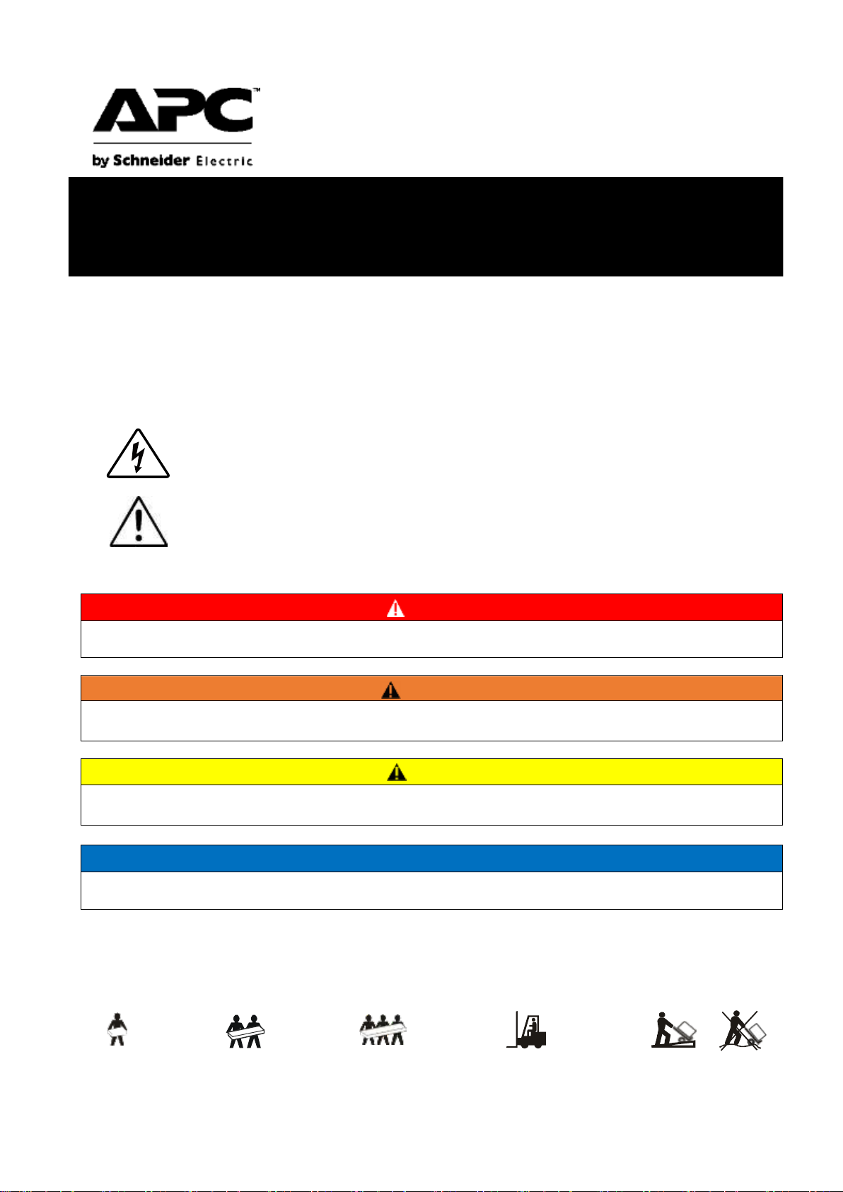
The use of the "Danger" or "Warning" safety label indicates that failure to follow
instructions thereof could result in a risk of electric shock, which may lead to personal injury.
This is a safety warning symbol, by which to alert you to potential personal injury risks.
Please observe all safety information thereof to prevent personal injury or death.
DANGER
DANGER indicates a hazardous situation which, if not avoided, will result in death or serious
injury.
WARNING
WARNING indicates a hazardous situation that, if not avoided, could result in death or serious
injury.
CAUTION
CAUTION indicates a hazardous situation which, if not avoided, may result in minor or moderate
injury.
NOTICE
NOTICE is used to place emphasis on those operations that post no threat to user but still
important.
<18 kg
18-32 kg
32-55 kg
>55 kg
<40 lb
40-70 lb
70-120 lb
>120 lb
Installation and operation
™
Back- UPS
BK500M-CH / BK650M2-CH
Important Safety Information
Before the installation, operation, or maintenance of this product, please carefully read through this manual and get
familiar with this product. The following safety information may appears throughout this manual or be printed on the
device, which is to raise you attention to potential hazards, operating instructions or any simplified information thereof.
Product Handling Guidelines
Page 2
2
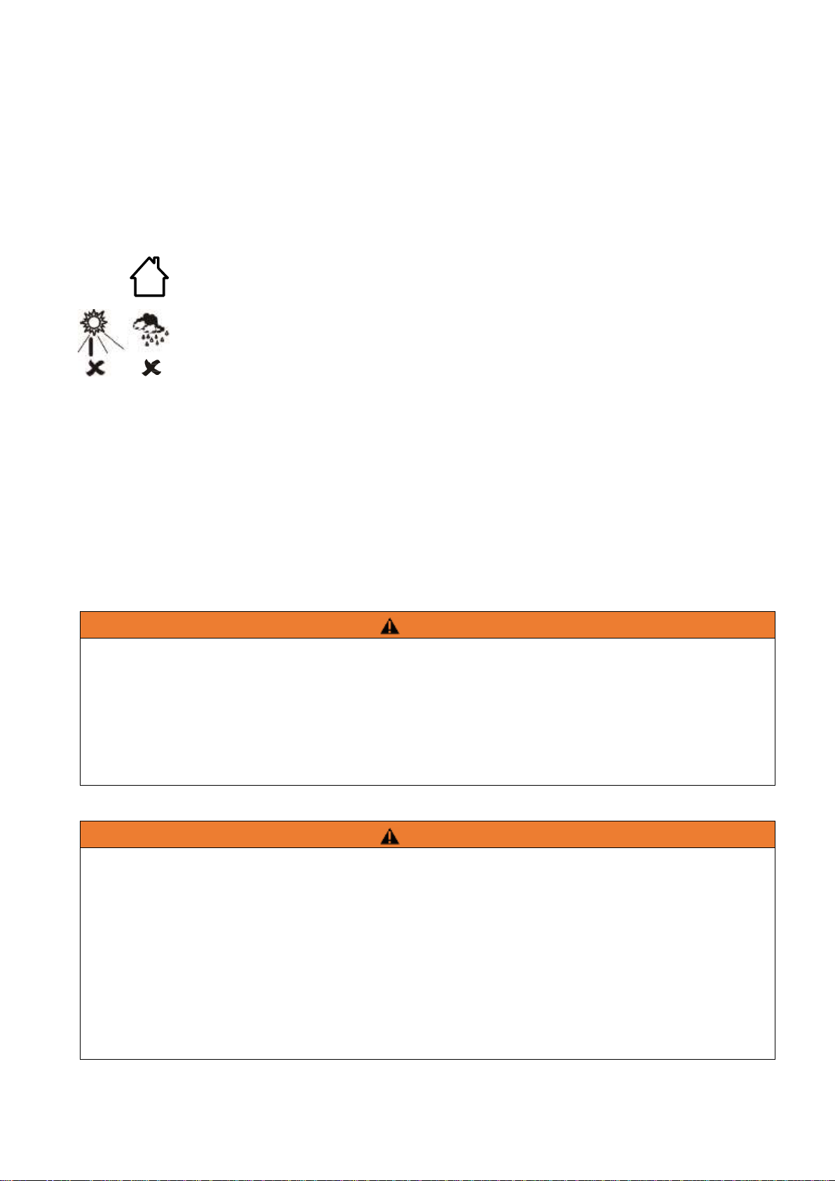
This device is intended for indoor use only.
Do not use the device in a place exposed to direct sunlight, liquids, excessive dust, or
excessive humidity.
The battery has a lifetime of two to five years, depending on the environmental factors can
affect battery life. High temperatures, unstable utility power, and frequent short-term
discharges can be the factors shorting the battery life.
Connect the Back-UPS power cord to a wall outlet directly without any intermediate
appliances such as surge protectors and power extension cords.
Please read all instructions in this installation manual before installing or using the UPS
system.
All safety instructions in this document must be read, understood, and strictly followed.
WARNING
Beware of overheating
• Observe the space requirements around the UPS system, and do not cover the vents of the product while the UPS is
in operation.
• The outlet used here shall be a grounded one.
• The outlet should be near and easily accessible to the UPS.
Failure to follow the instructions could result in serious consequences such as personal injury or equipment
damage.
WARNING
Observe the following precautions when handling the battery
• Remove watches, rings and any other metal objects.
• Use tools with insulated handles.
• Wear rubber gloves and boots.
• Do not place tools or metal parts on top of the battery.
• Disconnect the charging power before connecting or disconnecting the battery terminals.
• Check if the battery is inadvertently grounded. If so, remove it from the ground. Contact with any part of a
grounded battery may cause an electric shock. Eliminating such grounding connection can greatly reduce the
possibility of electric shock incidents during the installation and maintenance.
Failure to follow the instructions could result in serious consequences such as personal injury or equipment
damage.
Basic Safety Information
Installation and operation guide for Back-UPS BK500M-CH / BK650M2-CH
Page 3

3
Installation and operation guide for Back-UPS BK500M-CH / BK650M2-CH
DANGER
Beware of electric shock, explosion and arc
The UPS is not intended for and shall not be installed in the following inadequate operating environments,
which are:
• Full of hazardous fumes.
• Full of moisture, dust, dust, steam, or high humidity.
• Prone to mold, insects, or parasites.
• Full of salty air, cooling water, fumes, acids or other impurities.
• With a pollution degree rating higher than 2 according to IEC 60664-1.
• Subject to abnormal vibration, shock, sway, or earthquake.
• Exposed to direct sunlight, heat, or strong electromagnetic fields.
Failure to follow the instructions could result in serious consequences such as personal injury.
DANGER
Beware of electric shock, explosion or arc
• Battery maintenance should be performed or supervised by personnel familiar with relevant technical
expertise.
• Do not throw the battery into a fire. Otherwise an explosion may occur.
• Do not disassemble, modify, or destroy the battery. The electrolyte flowing from the battery can damage
human skin and eyes. The electrolyte may also be toxic.
• The battery replacement may produce a risk of electric shock and high short-circuit current and shall not
be conducted by users.
• The battery replacement, which shall be conducted by technician, shall be done with the same number
and specifications of batteries or battery packs.
• A failed battery will product more heat that makes its temperature of accessible surface potentially high
enough to cause skin burn injuries.
• Replacement with batteries of the wrong type and specification may cause an explosion hazard. Always
dispose of a used battery in accordance with the instructions.
Failure to follow the instructions could result in serious consequences such as personal injury.
CAUTION
Risk of hydrogen sulfide gas and dense smoke
• Replace the battery at least every 5 years.
• When the UPS prompts and requires a battery replacement, it should be conducted immediately.
• Replace the battery when it reaches the end of its life cycle.
• The number and type of replacement batteries must be the same as those of the original batteries in the
device.
• When the UPS indicates that the battery temperature is too high, or that the internal temperature of the
UPS is too high, or there are signs of electrolyte leakage, the battery should be replaced immediately. To
do so, the UPS shall be turn off, unplugged from the AC input, and disconnected from the battery. Do not
operate the UPS until the battery replacement is complete.
Failure to follow these instructions may result in injury.
Environmental requirements
• This equipment is intended for indoor use only. The storage location of the equipment should be solid
and reliable.
• Do not use the UPS in an environment that is full of dusty or the temperature / humidity of which is out
Page 4
4
Temperature
Operation
0°C to 40°C (32°F to 104°F)
storage
-15°C to 40°C (5°F to 104°F)
(The battery shall be recharged every 3 months)
Humidity
Relative
humidity
0% - 95% (non-condensing)
Altitude
0 ~ 3000 meters ( Battery capacity is derated 1% for every 100
meters above 1000 meters
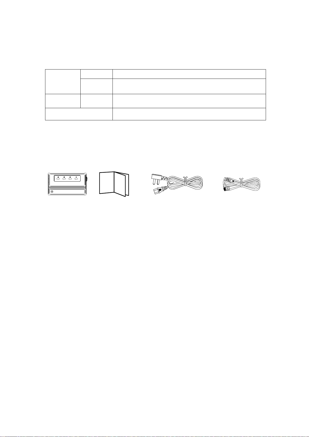
Back-UPS x 1
Manual x 1
Power cable x 1
Communication
cable x 1
(Only for
BK650M2-CH)
of the specification limits.
• A ventilation space of at least 30 cm must be reserved for the ventilation openings on this equipment.
• Battery life is subjected to environmental factors. High temperatures, poor utility power, and frequent
short-term discharges can shorten the battery life.
Packing list
Turn on Back-UPS
By a press on the power button, the power button lights up in green with a short alarm sound, indicating
that the Back-UPS is turned on and starts providing protection for the connected equipment. As long as the
Back-UPS is connected to utility power, the Back-UPS charges its battery whether it is turned on or not and the
battery will be fully charged in 24 hours. If the red wiring error indicator, which is near the power cord, is on, the
ground wire may be connected wrong and presents a risk of electric shock, which shall be corrected by a
qualified electrician immediately.
™
PowerChute
Overview With this PowerChute Personal Edition software, you can use your computer to access additional
Back-UPS power protection and management features. You can:
Save work in progress by putting your computer into hibernation mode during a power
outage. When the power returns, the computer will display exactly the same content as
before the power failure.
Configure Back-UPS management functions, such as power-saving sockets, shutdown
parameters, and audible alarms.
Monitor and view the status of the Back-UPS, including estimated runtime, power
Personal Edition software
Installation and operation guide for Back-UPS BK500M-CH / BK650M2-CH
Page 5
5
Installation and operation guide for Back-UPS BK500M-CH / BK650M2-CH
consumption, and power event history.
Available features will vary depending on the Back-UPS model and your operating system.
If you choose not to install PowerChute, Back-UPS will still provide backup power and power
protection for connected devices. However, you can only use the display interface to configure a
limited number of features.
Compatibility PowerChute is only compatible with Windows operating systems. For a detailed list of
supported operating systems, please visit https://www.apc.com/wp/?um=300 and
download it.
For MAC operating systems, we recommend using the native shutdown application (in <System
Preferences), which recognizes your battery backup device and allows you to configure how the
system shall act upon a power outage incident. To use this application, connect the Back-UPS’s data
port (POWERCHUTE USB PORT) to a USB port on your computer using a USB cable, and then see
and follow the instructions given by the documentation that came with your computer.
Installation guide Connect the Back-UPS to the computer using a USB cable. Plug one end into the
POWERCHUTE port on the back panel of the Back-UPS, and the other end into the USB port on the
computer. Then visit www.apc.com/pcpe, select <Software download> to download and install it.
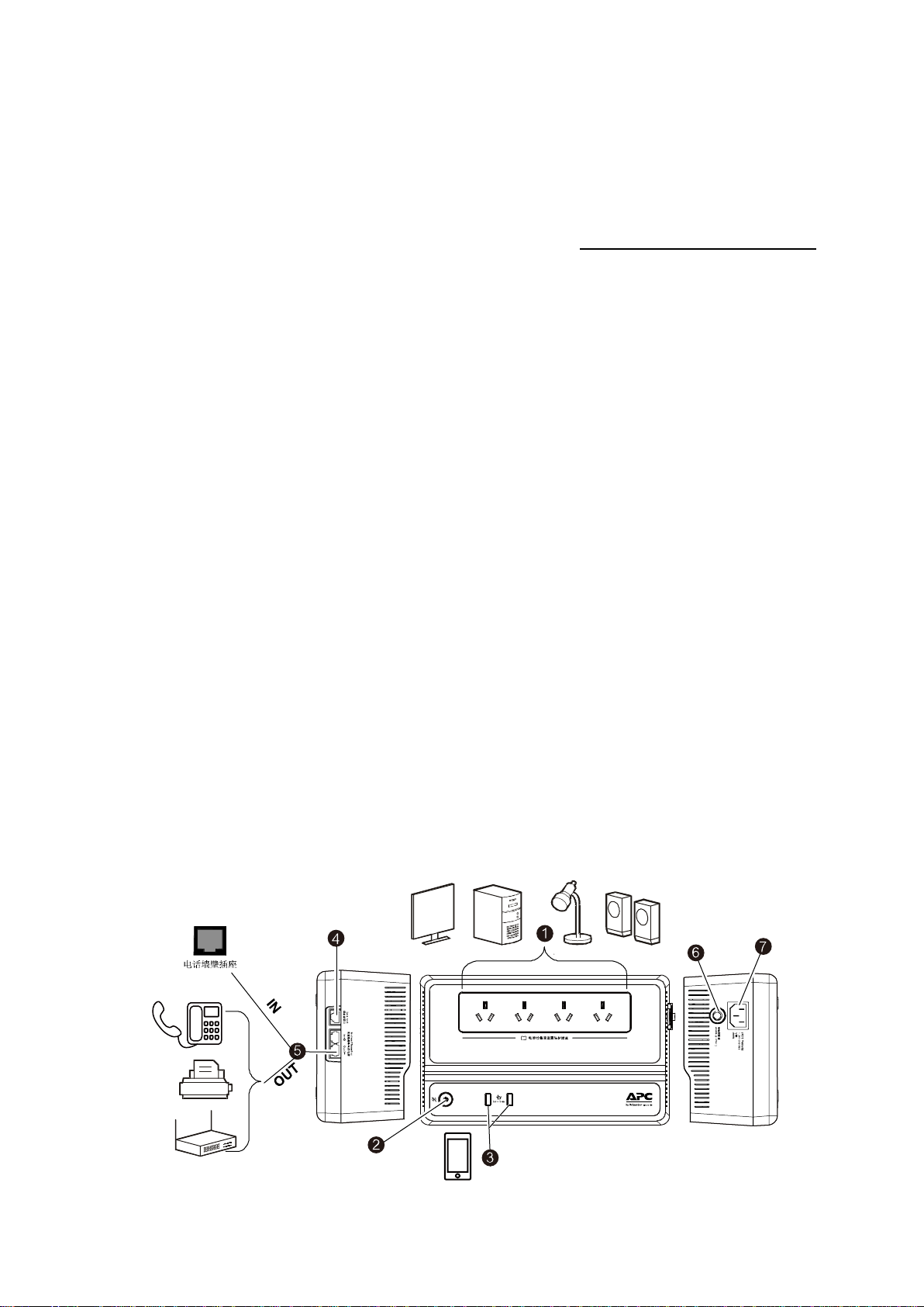
Connect your devices
Batteries and surge-proof sockets
Power on/off button
USB charging interface (only for BK650M2-CH)
Data communication port (only for BK650M2-CH)
Modem / Telephone / Fax (only for BK650M2-CH)
Power protection circuit breaker
Mains input
Page 6

6
Power On / Off button
Press the on / off button on the front panel. The UPS will emit a short beep along
with the green Power On indicator lights on, indicating that the UPS is on and starts
providing power protection.
If this is the initial usage, the Back-UPS need to be charged for 6-8 hours to
provide the longest working time. When the Back-UPS is connected to utility power, it
starts charging the battery whether it is on or off. The battery may not provide the
rated battery operating time during this initial charge.
Circuit breaker
Used to reset the system after an overload condition that causes the circuit
breaker to trip.
Mains power cord
Use this power cord to connect the Back-UPS to your utility power.
Battery backup socket
+ anti-surge
These outlets provide battery backup power to connected devices a limited
period of time during power outages and voltage fluctuations.
The battery backup power socket provides battery power to the connected
devices only when the Back-UPS is on. Connect here your critical devices such as
computers, computer monitors, modems, or other data-sensitive devices.
Do not connect aquarium equipments, laser printers, paper shredders, sewage
pumps, or fans to these outlets, as the approximate sine wave output from the BackUPS may cause performance degradation of these devices.
Do not connect surge protectors or extension cords to these outlets.
Turn off Back-UPS
Press and hold the power button for at least 2 seconds, and release the button after hearing a short beep.
This will turn off your Back-UPS. The 2-second delay design is to prevent the power button being accidentally
pushed.
Quick mute
Back-UPS allows the buzzer sound being stopped temporarily in certain modes, such as the battery mode.
When the buzzer sounds in such modes, a quick press (less than 2 seconds) on the power button can
temporarily stop the buzzer sound until a state reset. The UPS makes two short beep sounds when the quick
mute feature is activated. Pressing and holding the power button for more than 2 seconds will turn off the UPS.
In other emergency incidents, such as battery replacement and charger warning, this mute feature is not
available and the UPS must be turned off.
Alarm sound setting in battery mode
Press and hold the power switch button for about 10 seconds and wait for 3 beeps. After the third beep, the
power switch button starts flashing between red and green and you can release the power button. The UPS is
now in the battery mode alarm setting mode. Afterward you can shortly press the power switch button to cycle
Installation and operation guide for Back-UPS BK500M-CH / BK650M2-CH
Page 7

7
Installation and operation guide for Back-UPS BK500M-CH / BK650M2-CH
through each setting modes. For those modes, please refer to the table below, where there are three indicators
LED indicator
Sensitivity
Input voltage range (on line
mode)
Green
Low
(160VAC~278 VAC)(Default)
Red
Middle
(180 VAC ~266 VAC)
Yellow
High
(196 VAC ~256 VAC)
Mode Indicator
Audio alarm
Indicator’s color
Silent alarm
(Default)
The power button
flashing green twice every
2 seconds at first. Once a
low battery notification
occurs, it quickly flashs
green.
No alarm sounding at first.
Once a low battery notification
occurs, beeps twice every 30
seconds.
Flasing green
No-alarm
No alarm sounding in the
battery mode.
Flashing red
Alarm-sounding
Once a low battery
emergency notification occurs,
the buzzer beeps once every
0.5 seconds. After the UPS is
turned off, it beeps once every
4 seconds.
Flashing yellow
with different colors respectively used to represented each mode. Once the setting is completed, wait 5 seconds
and the UPS will complete the setup.
Voltage sensitivity adjustment
Adjust the voltage sensitivity for the Back-UPS to control the timing when the Back-UPS switches to the
battery mode. The higher this sensitivity, the more frequently the Back-UPS switches to the battery mode.
1. Confirm that the Back-UPS is connected to utility power and is turned off.
2. Press and hold the power button for 10 seconds. When the power button starts flashing green and red,
the UPS is ready for voltage adjustment.
By a short press on the power button afterward, the blinking color of the indicator changes and cycles
through green, yellow and red, by which to indicate sensitivity level. Please refer to the following table
for related voltage sensitivity levels.
3. When the setting is completed, please wait 5 seconds. When all LED indicators go out, the UPS has
finished and exited the voltage programmable mode.
Page 8

8
Status
Power indicator
Buzzer beeping
Stop buzzer from
beeping
Power on
The input mains power is
normal, and the load is
powered by the utility
power.
Green
N/A
N/A
Battery mode
Load is powered by battery
Flashing green twice
every 2 seconds
The buzzer beeping is
set according to the
status of the battery
mode
See "Battery Mode
Alarm Settings" for
details
- -Use the quick mute
feature
- -When the mains power
is restored or the BackUPS is turned off, the
beep will stop. But in the
battery mode, it still
keeps beeping.
Low battery notification
Powering the load, the
battery is about to be used
up.
Flashing green
rapidly.
Low battery shutdown
In the battery mode, the
UPS shuts down directly
because of complete
battery drain.
N/A
- Mains power is restored
- Back-UPS will shut down
if mains power is not
restored within 32
seconds.
Sleep mode
The UPS has been shut
down and will restart upon
utility power restore
N/A N/A N/A
Battery replacement
The battery needs to be
charged or replaced
Flashing between
green and red
Continuous beeping
- Turn off the UPS
- Start charging the battery
by connecting to the
mains
- In the case of battery
replacement, please
contact APC sales
department for technical
support
Overload
In battery mode, one or
more power outlets are
overloaded
Flashing between
green and red
Beep every 0.5 second.
-
Turn off the UPS
Status indicator and buzzer
Installation and operation guide for Back-UPS BK500M-CH / BK650M2-CH
Page 9

9
Installation and operation guide for Back-UPS BK500M-CH / BK650M2-CH
Troubleshooting
Problem and possible cause
Solution
Back-UPS cannot be turned off
Back-UPS is not connected to utility power.
Mains power does not exist or its voltage is too low /
high.
Reinsert the UPS input power cord into a power outlet.
Make sure that the outlet is supplied with mains power
and the power switch is turned on.
Back-UPS shows it is turned on but the power
button flash between green and red and the
buzzer sounds continuously.
The battery is in the end of its life cycle and needs
to be replaced.
Contact APC Sales for technical support.
No power is supplied to the connected devices.
Back-UPS is overloaded.
Remove all the devices from the output sockets and then
reconnect the devices one at a time.
Charge the battery for 24 hours to make it fully charged. If
the overload condition persists, replace the battery.
Back-UPS’s battery is completely drained.
Reconnect Back-UPS to mains power and recharge the
battery for 8 hours.
The power waveform provided by this UPS is not
compatible with the requirements of the connected
devices
The UPS’s output waveform is designed for computers
and related appliances but not for motor-driven devices.
Back-UPS requires technical service.
Contact APC Sales for technical support.
The power button flashes green twice every 2
seconds
Back-UPS is in the battery mode.
Back-UPS works normally in the battery mode.
In this case, users should save all open files and data to
disk and shut down the computer.
The battery will be recharged after the mains power is
restored.
The power button flashes green rapidly.
Back-UPS’s battery power is too low.
The battery is about to be drained, and users should save
all open files and data to disk and shut down the
computer.
The battery will be recharged after the mains power is
restored.
The red indicator lights up.
There is a possible risk of electric shock, and needs
for qualified repair technicians.
Do not operate Back-UPS any further.
Call qualified technicians for technical service.
Back-UPS cannot provide sufficient battery
operating time.
The battery is not fully charged.
The battery is at the end of its life cycle and needs
to be replaced.
Connect your Back-UPS to utility power for 8 hours to
allow the battery to be fully charge. The battery life and
capacity decrease with age and usage. For how to order
batteries for replacement, please see Troubleshooting.
The wall socket is normal but the alarm sounds
continuously and the power button flashes
between green and red.
The UPS is in the on-line mode, but the connected
devices causes the UPS to be overloaded.
If a power outage occurs, the UPS cannot provide
enough power for all the connected devices.
The power output sockets remains operational as
Remove excess connected devices to make the load
below the UPS output specifications.
Page 10

10
long as the mains power is normal.
The UPS shutdowns by itself few seconds after
the alarm sound and the power button flashing
green and red.
The UPS is in battery mode and the load of the
connected devices exceeds the UPS’s capability.
Turn off the UPS and remove all connected devices.
Turn on UPS and connect one device at a time to it.
Installation and operation guide for Back-UPS BK500M-CH / BK650M2-CH
Page 11

11
Installation and operation guide for Back-UPS BK500M-CH / BK650M2-CH
Specification
BK500M-CH/BK650M2-CH
Model No.
BK500M-CH
BK650M2-CH
Input
Voltage
220-240VAC (220VAC in default)
220-240VAC (220VAC in default)
Voltage range
160 VAC ~ 278 VAC
160 VAC ~ 278 VAC
Output
UPS capacity
500VA/300W
650VA/390W
Voltage in battery mode
220-240 (programmable) VAC ± 8%
(Approximate sine wave)
220-240 (programmable) VAC ± 8%
(Approximate sine wave)
Frequency in battery mode
50/60 Hz ± 1 Hz
50/60 Hz ± 1 Hz
Transfer time
6ms(Typical);10ms(Max.)
6ms(Typical);10ms(Max.)
Protection and filtering
AC Surge Protection
310 J
310 J
AC input
Resettable circuit breaker (5A/250VAC)
Resettable circuit breaker (5A/250VAC)
Battery
Type
Lead-acid maintenance-free
Lead-acid maintenance-free
Battery specifications
12V/5Ah x1
12V/27W x1
Normal charging time
8小时
8小时
Interface
USB charging port
N/A
TypeA×2 (5V/2.4A)
USB communication port
N/A
RJ50
Telephone & Network Surge
Protection jack
N/A
RJ45
Physical
Operating temperature
0°C ~ 40°C
0°C ~ 40°C
Storage temperature
-15°C ~ 40°C
-15°C ~ 40°C
Relative humidity
0 ~ 95%(Non-condensing)
0 ~ 95%(Non-condensing)
Working altitude
0 ~ 3000 m
0 ~ 3000 m
Product Weight
2.9 kg
3.2 kg
Product size (H x W x L mm)
105 x 171 x 286
105 x 171 x 286
IP rating
IP 20
IP 20
Package gross weight
3.2 kg
3.5 kg
Packing size (H x W x L mm)
241 x 142 x 322
241 x 142 x 322
* If the UPS is installed and used in an environment where the altitude exceeds 1000 meters, the capacity
ought to be reduced by 1% for every 100 meters of elevation.
Page 12

12
Wall mount
• Horizontal installation, using 2 screws with 150 mm (5.9 inches) apart.
• Vertical installation using 2 screws with 122 mm (4.8 inches) apart.
• The protruding part of the wall mount screws shall be 5 mm (3/16 inch) from the surface.
Installation and operation guide for Back-UPS BK500M-CH / BK650M2-CH
Page 13

13
Installation and operation guide for Back-UPS BK500M-CH / BK650M2-CH
Battery replacement
Warning: The battery may cause electric shock and high short-circuit current, and can only be replaced by
qualified service personnel. Before replacing the battery, pay attention and remember to remove watches, rings or
other metal objects, and use tools with insulated handles. Proceed as follows:
Service
If your UPS needs service, do not return it to your dealer. Please follow the steps below:
1. Read the Troubleshooting section of this manual to troubleshoot common issues.
2. If the problem still persists, contact APC Customer Support by visiting the APC website www.apc.com.
a. Write down the model, serial number, and date of purchase. The model and serial number can
be found on the rear panel of the device.
b. Call APC Customer Support and a technician will try to resolve the issue over the phone. If this
does not resolve the issue, the technician will provide you with a Return Material Authorization
Number (RMA #).
c. If the device is under warranty, it will be repaired free of charge.
d. Repair and return procedures may vary by country. Visit the APC website for specific
instructions for each country.
3. Pack the device properly to prevent damage during transportation. Never use foam pellets. Damage caused
during transportation is not covered by the warranty. The battery can remain in the device.
4. Please quote the Return Material Authorization Number (RMA #) provided by Customer Support on the
outside of the package.
5. Return the device to the address provided by the customer support department through a shipping company.
When shipping, please cover insurance on it and pre-pay the freight.
Page 14

The Names and Contents of the Hazardous Substances
Parts Name
Pb
Hg
Cd
Cr(VI)
PBB
PBDE
Mechanical Assemblies
X O O O O
O
Electronic parts
X O X O O
O
Wire Assemblies
X O O O O
O
Batteries (if have)
X O O O O
O
This table is prepared in accordance with the provisions of SJ/T 11364.
O Indicates that said hazardous substance contained in all of the homogeneous materials for this part is below
the limit requirement of GB/T 26572.
X Indicates that said hazardous substance contained in at least one of the homogeneous materials used for
this part is above the limit requirement of GB/T 26572.
Hazardous
MCV
Substance
Pb, Hg, Cr(VI), PBB, PBDE
1,000 PPM
Cd
100 PPM
APC Customer Support (China)
Company website http://www.apc.com/cn
Telephone number
+ 86 400 810 1315
Warranty service
This product comes with a two (2) year standard warranty from the date of purchase. The APC standard
procedure is to replace the original unit with a factory refurbished unit.
If the returned equipment has an asset tag assigned and a depreciation schedule has been set up, and the
customer must retrieve the original equipment, this need must be clarified when the APC Technical Support
Representative is first contacted. As soon as the repair department receives the defective device, APC will ship the
replacement device immediately; or if a valid credit card number is received, APC can ship the replacement device at
the same time the customer sends the device back. The customer is responsible for paying the shipping cost of the
equipment to APC. APC pays for the ground freight for the equipment returned to the customer.
Hazardous Substances Statement
In accordance with China’s Administrative Measures for the restriction of hazardous substances in Electrical and
Electronic Products (EEP) # 32, also known as China RoHS, the information is provided regarding the names and
concentration levels of Hazardous Substances which may be contained in Schneider Electric products relative to the
EEP standards set by China’s Ministry of Industry and Information Technology.
© 2019 APC by Schneider Electric. APC, APC logo, and Back-UPS are owned by Schneider Electric
Industries S.A.S., American Power Conversion Corporation, and their subsidiaries. All other trademarks are
the property of their respective owners.
10/2019
EN 990-6185
 Loading...