

Page 1

®
w w w
.apc.com
Power Inverter
Model BI800T and BI800F
Installation Guide and User’s Manual
990-1810A Copyright © 2004 American Power Conversion. All rights reserved.
APC is a registered trademark of American Power Conversion. All other trademarks are the property of their respective owners.
Page 2

CONTENTS
Page
Overview 1
Checklist 1
Section 1. Unpacking/Inspection (at reseller location) 2
Main Housing Chassis and Inverter 2
Battery Inspection 2
Unpack Battery 2
Inspect Battery 2
Clean battery 2
Remove Battery from Shipping Container 2
Check Battery Fluid Level 2
Check Battery Charge Level 3
Repackage Battery 3
Section 2. Unpacking/Inspection (at customer location) 3
Main Housing Chassis and Inverter 3
Battery Inspection 4
Unpack Battery 4
Inspect Battery 4
Clean Battery 4
Remove Battery from Shipping Containe 4
Check Battery Fluid Level 4
Check Battery Charge Level 4
Section 3. Installation 1
Main Housing Placement 4
Location Selection 4
Lock Wheels 4
Battery Installation 4
Main Housing Chassis Rear Panel Removal 4
Install a Battery 5
Battery Connections 6
Install Main Housing Chassis Rear Panel 6
Install Inverter 6
Install Wiring Management Kit 7
Section 4. Controls and Indicators 9
Inverter Controls 9
AWAY/HOME 9
TEST/MUTE 9
Circuit Breaker Switch 9
Inverter Indicators 9
Section 5. Troubleshooting 12
Manual Bypass 12
Preventative Maintenance 13
Specifications 14
Warranty 15
Contact Information 15
i
Page 3

CONTENTS - continued
FIGURES
Page
Figure 1. APC Power Inverter 1
Figure 2. Battery Elements (tubular battery shown) 2
Figure 3. Battery Fill Cap Elements 3
Figure 4. Main Housing Chassis Rear Panel Removal 5
Figure 5. Battery Installations and Connections 6
Figure 6. Inverter Assembly Placement 7
Figure 7. Typical Home Wiring Before Inverter Installation 7
Figure 8. Typical Home Wiring After Inverter Installation 8
Figure 9. Power Inverter Connections 8
Figure 10. Wiring Management Kit Installation 9
Figure 11. Power Inverter Front Panel Controls and Indicators 10
Figure 12. Power Inverter Bypass Connection 13
TABLES
Table 1. Power Inverter Indicators 10
Table 2. Power Inverter Troubleshooting 12
Table 3. APC Power Inverter Technical Specifications 14
ii
Page 4
Thank you for purchasing APC’s Power Inverter. Please fill out the enclosed Warranty Registration Card, or register your purchase on-line
at: www.apc.com/support.
Overview
APC’s Power Inverter (Figure 1) is designed for years of trouble-free use. The Inverter is a sinewave back-up power supply intended to
serve house loads. It is rated for 800 VA/500W at 230 Vac, 50-Hz, and operates on a wide range of input voltages (100 - 265V). If the input
voltage goes out of range (less than 100V or more than 265V), the utility is isolated and the inverter supplies power to the load from the
internal batteries. The Inverter can serve inductive loads (flourescent lamps, ceiling and table fans), resistive loads (incandescent lamps),
and switched mode power supply (SMPS) loads (television). The typical backup time with the primary battery pack at full load is
approximately two (2) hours. Backup time can be further extended by connecting the optional external battery pack in parallel to the
existing battery pack.
Note: APC offers tubular, as well as flat-plate batteries for use with the Power Inverter.
For the purposes of this manual, only the tubular batteries are shown.
Checklist:
Depending on what the customer has ordered, ensure the following items have been delivered:
• Inverter
• Batteries (2), Tubular Batteries Shown
• Main Housing
• Wiring Kit
• Fill Kit (rubber gloves and a funnel)
• Wire Management Kit
• Parallel Wiring Kit (if external battery pack was ordered - not shown)
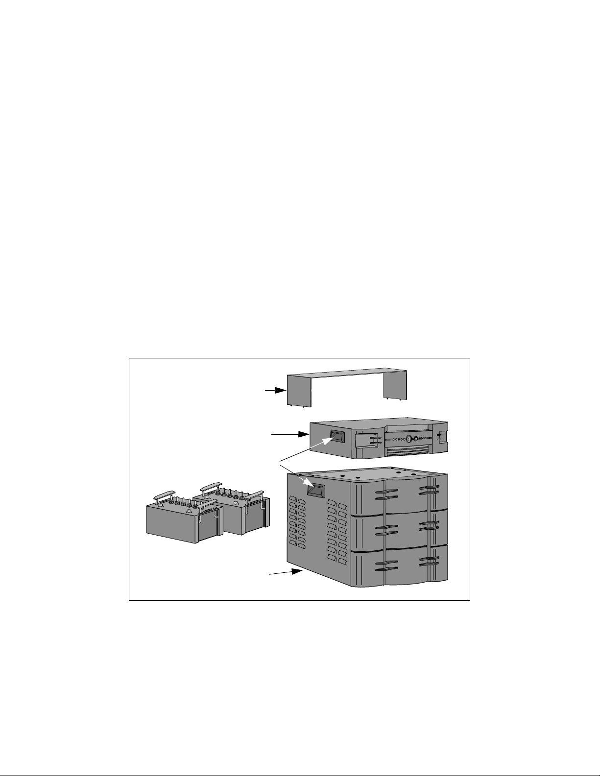
Wire Management Kit
(Optional)
Inverter Assembly
Handles
(1 each side)
Batteries
Main Housing Chassis
(Wire Harness Not Shown)
Figure 1. APC Power Inverter
Page 1
Page 5
Section 1. Unpacking/Inspection (at reseller location)
Main Housing Chassis and Inverter
Warning: The Main Housing Chassis weighs 18 kg. Two-person lift required. Failure to
comply may result in personal injury.
!
Inspect the shipping containers for signs of obvious damage. If damage to either shipping container is extensive, notify the carrier
and return the unit to the factory. If there are no apparent signs of damage, carefully open the container, and remove the packing
materials (do not discard). To remove the Main Housing Chassis or Inverter Assembly from the shipping container, grasp the
handles located on each side of the housing or inverter (Figure 1), and remove the item from the container. Inspect each for: dents,
scratches, broken or missing wheels (housing only), warpage of the top cover, or other signs of damage. If either unit is damaged,
please notify the factory and obtain a Return Material Authorization number and return the unit as/if instructed. If there are no
obvious signs of damage, repackage the unit for shipment to the customer using the materials already removed from the shipping
container. Ship or otherwise deliver the unit to the customer location.
Battery Inspection
Unpack Battery - Inspect the battery shipping container for signs of obvious damage. Carefully inspect the container for signs
of a leaking battery. If the shipping container shows signs of leakage, the battery may be damaged. Contact the factory for
instructions to further inspect the battery inside the container, or for return instructions. Carefully open the shipping container
and remove the packing materials (do not discard).
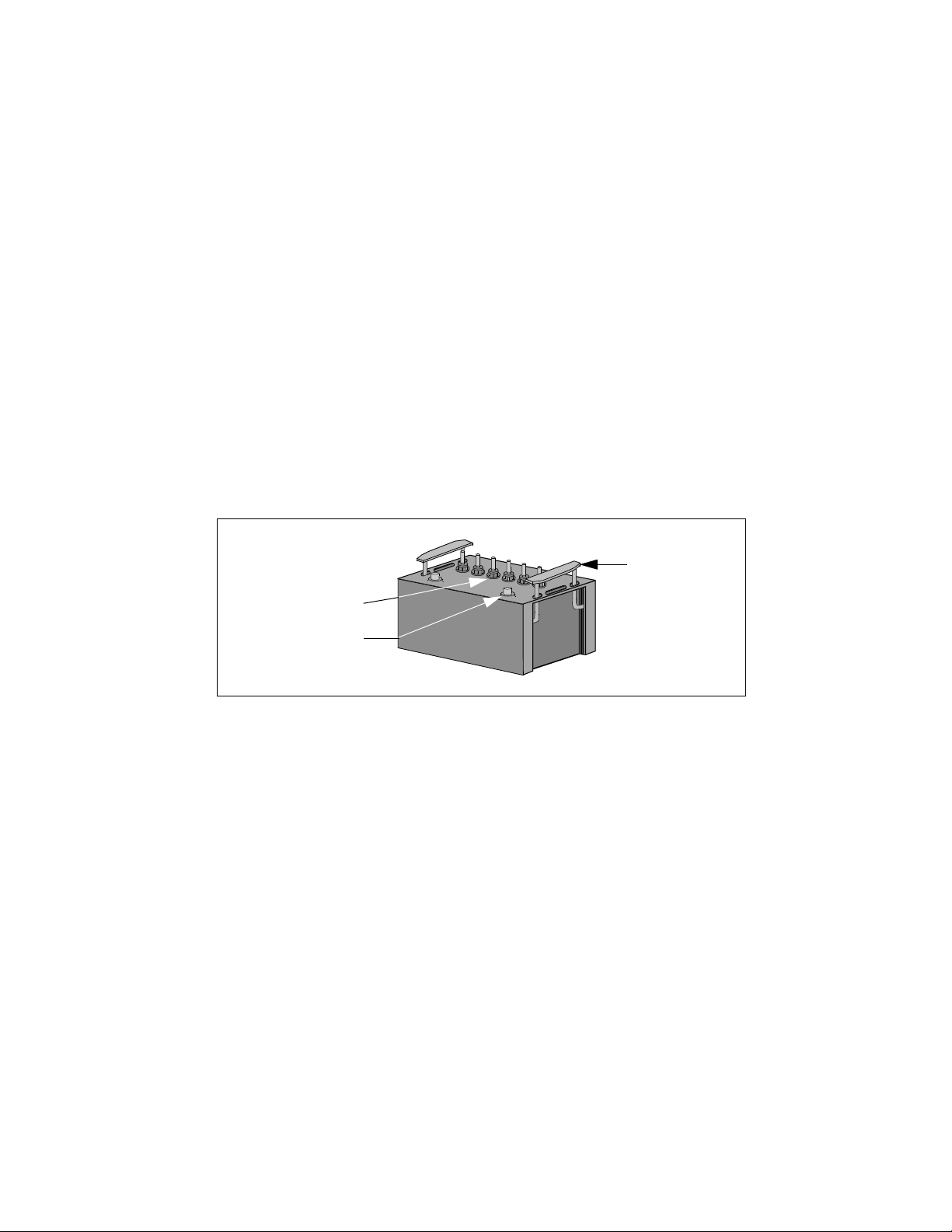
Inspect Battery - If there are no obvious signs of damage or leakage, with the battery in the shipping container, inspect the
battery for leaks, cracks, broken wiring terminals, broken handles, and broken fill caps (Figure 2).
Battery Handle
(1 each side)
Battery Fill Cap (6)
Battery Terminal (2)
Figure 2. Battery Elements (tubular battery shown)
Clean battery - If the inspection shows signs of a leaking battery, put on rubber gloves and remove the battery fluid/residue
from the battery housing using a mixture of baking soda and distilled water. If cracks or other damage is noted after cleaning the
battery, contact the factory for return or disposal instructions.
Warning: Each battery weighs 28 kg. Two-person lift required. Failure to
comply may result in personal injury.
!
Remove Battery from Shipping Container - Remove the battery from the shipping container by grasping the handles (see
Figure 1) located at each end of the battery. Lift the battery straight up and out of the shipping container.
Check Battery Fluid Level - After cleaning and inspection for damage, check the battery fluid level of each cell (Figure 3). If
the fluid level of any cell is not within the specified range on the fill cap, put on rubber gloves (from Fill Kit), remove the
battery cell cap, and fill the cell with distilled water using the funnel provided in the Fill Kit. Install the cell cap on each cell.
Page 2
Page 6
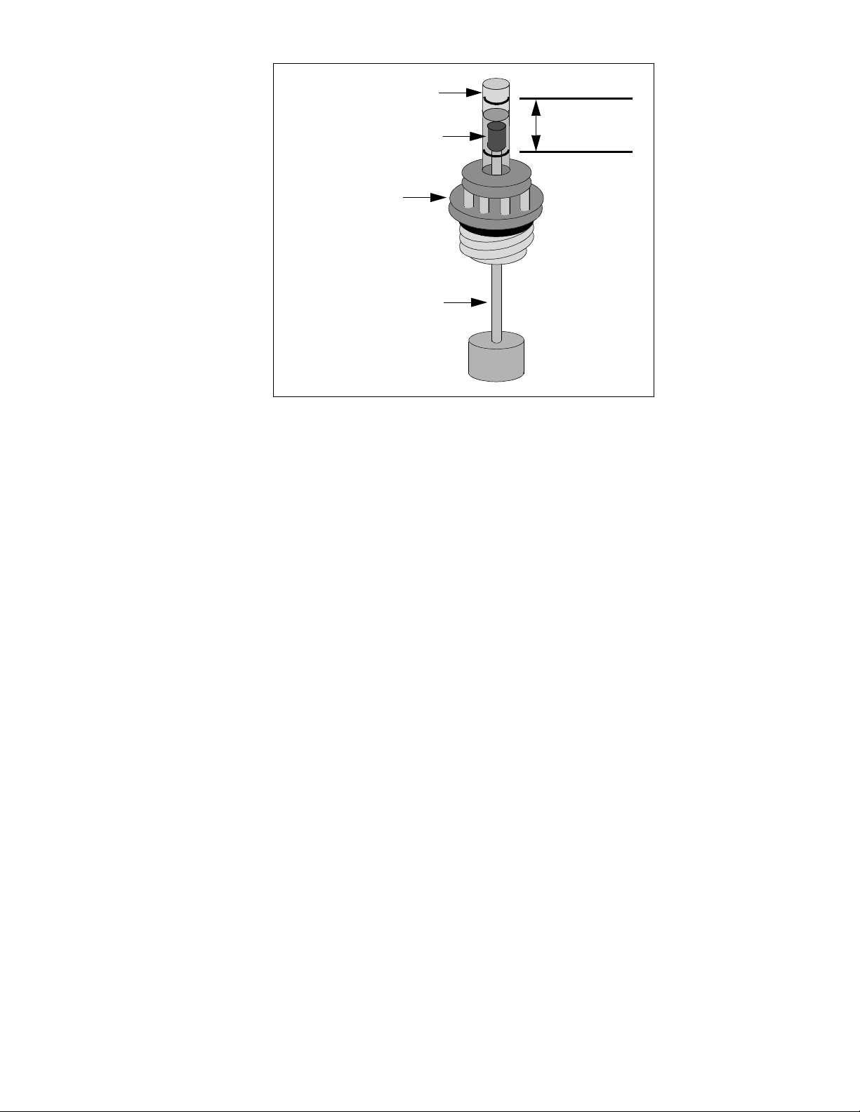
Fluid Level
Tube
Fluid Level
Indicator
Battery Fill Cap
Float Device
Figure 3. Battery Fill Cap Elements
Check Battery Charge Level - After filling battery cells (if necessary), check the battery specific gravity using a hydrometer.
The battery specific gravity should be between 1230 and 1250. If battery specific gravity is below 1230, charge the battery
using a battery charger until the battery specific gravity is within the acceptable range.
Optimum
Fill Range
Warning: Each battery weighs 28 kg. Two-person lift required. Failure to
comply may result in personal injury.
!
Repackage Battery - Place the battery in the shipping container by grasping the handles located at each end of the battery. Lift
the battery straight upwards and place it in the shipping container. Install packaging materials. Seal the shipping container, and
ship the battery to the customer location.
Section 2. Unpacking/Inspection (at customer location)
Main Housing Chassis and Inverter
Note: The Inverter Assembly is shipped with two (one male and one female) IEC
connectors for use in installing home wiring to/from the Inverter.
Inspect the shipping containers for signs of obvious damage. If damage to either shipping container is extensive, notify the carrier
and return the unit to the factory. If there are no apparent signs of damage to the shipping container, carefully open the container,
and remove the packing materials (do not discard).
Warning: The Main Housing weighs 18 kg. Two-person lift required. Failure
to comply may result in personal injury.
!
To remove the Main Housing Chassis or Inverter from the shipping container, grasp the handles located on each side of the Housing
or Inverter (Figure 1), and remove the item from the shipping container. Inspect each for: dents, scratches, broken or missing wheels
(housing only), warpage of the top cover, or other signs of damage. If either unit is damaged, please notify the factory and obtain a
Return Material Authorization number and return the unit as/if instructed. If there are no obvious signs of damage, proceed with
Battery Inspection.
Page 3
Page 7

Battery Inspection
Unpack Battery - Inspect the battery shipping container for signs of obvious damage. Carefully inspect the container for signs
of damage due to a leaking battery. If the shipping container shows signs of leakage, the battery may be damaged. Contact the
factory for instructions to further inspect the battery inside the container, or for return instructions. Carefully open the shipping
container and remove the packing materials (do not discard).
Inspect Battery - If there are no obvious signs of damage or leakage, with the battery in the shipping container, inspect the
battery for leaks, cracks, broken wiring terminals, broken handles, and broken fill caps (Figure 2).
Clean Battery - If the inspection shows signs of a leaking battery, put on rubber gloves and remove the battery fluid from the
battery housing using a mixture of baking soda and distilled water. If cracks or other damage is noted after cleaning the battery,
contact the factory for return or disposal instructions.
Warning: Each battery weighs 28 kg. Two-person lift required. Failure to
comply may result in personal injury.
!
Remove Battery from Shipping Container - Remove the battery from the shipping container by grasping the handles (see
Figure 2) located at each end of the battery. Lift the battery straight upwards and out of the shipping container.
Check Battery Fluid Level - After cleaning and inspection for damage, check the battery fluid level of each cell (Figure 3). If
the fluid level of any cell is not within the specified range on the fill cap, put on rubber gloves, remove the fill cap, and fill the
cell with distilled water. Install the fill cap on each cell. If battery fluid is discharged from the battery during the filling process,
put on rubber gloves and remove the battery fluid from the battery housing using a mixture of baking soda and distilled water.
Check Battery Charge Level - Ufter filling battery cells (if necessary), check the battery specific gravity using a hydrometer.
The battery specific gravity should be between 1230 and 1250. If battery specific gravity is below 1230, charge the battery
using a battery charger until the battery specific gravity is within the acceptable range.
Section 3. Installation
Main Housing Placement
Note: Once the unit has been completely installed, it is not desireable to move it.
Location selection - unlock the wheels located at the bottom of the Main Housing Chassis, and roll it to the desired location.
Ensure the area where the unit is to be placed is not in direct sunlight (surfaces may become hot). Further ensure the unit is
placed in a dry area away from sources of liquids, and that the vents on each side have at least 15 cm (6 inches) of unobstructed
clearance (Figure 4).
Lock Wheels - Lock the wheels to restrict movement during battery installation.
Battery Installation
Main Housing Chassis Rear Panel Removal - Remove the four machine screws (Figure 4) that secure the Rear Panel to the Main
Housing Chassis. Remove the Rear Panel and set it aside.
Page 4
Page 8
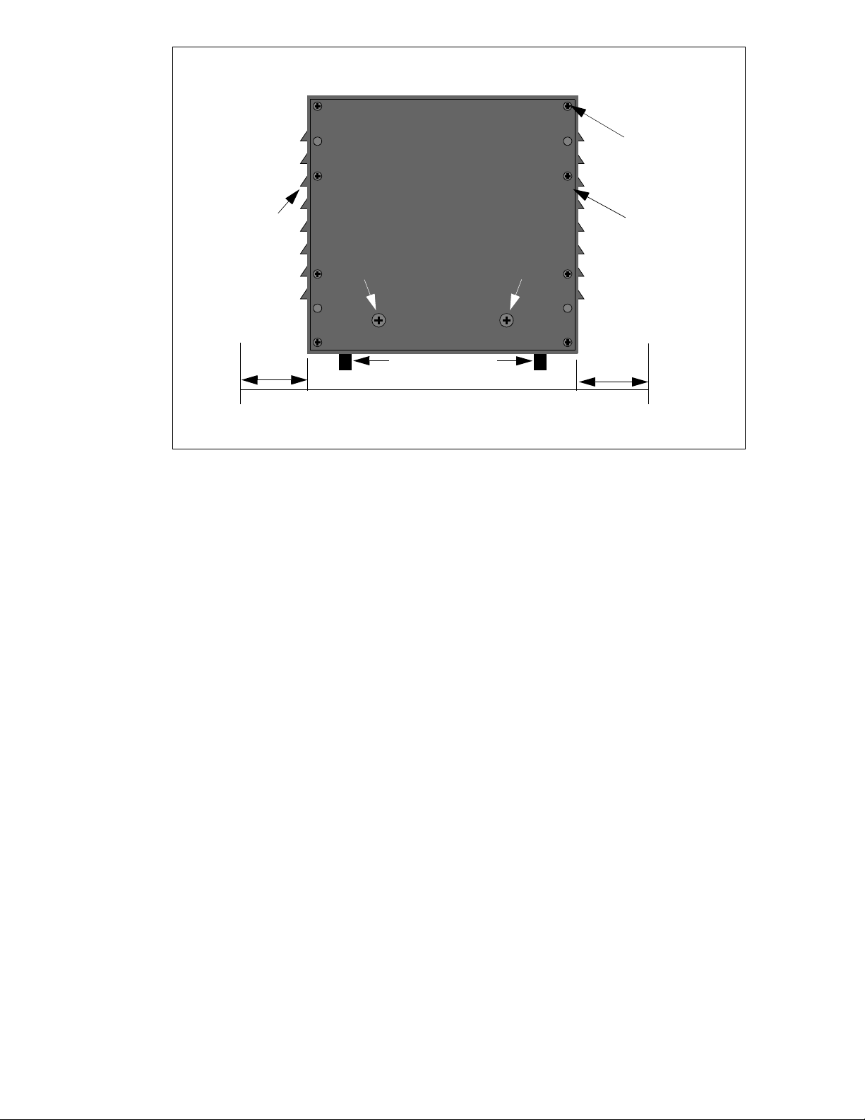
Main Housing Chassis (Rear View -
Wire Harness not Shown)
Remove the 4 corner
screws only.
Air Vents
(Each Side)
Do Not Remove These Two Screws
15 cm
(6 inches)
Note: Allow 15 cm (6 inches) of unobstructed
Figure 4. Main Housing Chassis Rear Panel Removal
Note: Access through the top of the Main Housing Chassis is provided for connecting and topping
(filling) of the batteries only.
Warning: Each battery weighs 28 kg, and must be installed through the opening at
the rear of the Main Housing Chassis and not through the opening in the top of the
!
unit. Failure to comply may result in personal injury and/or equipment damage
Wheels (4).
clearance on each side.
(6 inches)
Rear Panel
15 cm
Install a Battery - Raise the top lid of the Main Housing Chassis to provide visual access to the interior of the chassis (Figure 5).
Note: The batteries are installed with the long side of the battery going across the length of
the front panel.
Caution: Installation of the Power Inverter Batteries must be performed by a licensed and
qualified electrician. Failure to comply may result in equipment damage, and may also
void the Warranty.
At the rear of the Main Housing Chassis, position the first battery to be installed through the rear opening so that the positive (+)
terminal is to the right. Position the second battery so that the positive (+) terminal is to the left. Grasp the battery using the handles
(Figure 2) located at each end of the battery. Carefully lift the battery and slide it into the Main Housing through the rear opening.
Slide the first battery as far forward as it will go into the Main Housing Chassis. Repeat this step for the second battery until it is up
against the second battery.
Page 5
Page 9

Main Housing Chassis
(top cover not shown)
Main Housing Chassis
(top cover shown)
Battery
Handle
Negative
(-)
Ter mina l
First
Battery
Battery
Handle
Second Battery
(rotated 180 degrees)
Battery
Handle
Positive
(+)
Term ina l
Negative
(-)
Terminal
Black
(-)
Wire
Battery
Handle
Positive
(+)
Terminal
Red (+)
Wire
Positive (+)
Term ina l
Black
Wire
Negative (-)
Term ina l
Main Housing Chassis
(rotated 180 degrees)
Battery Installation Battery Connections
Figure 5. Battery Installations and Connections
Battery Connections - Note: The batteries are charged and produce electric current. Small sparks by be noted during the
connection process. This is a normal condition and does not pose a threat of injury.
Connect the red battery terminal lead (protrudes from the lid) to the positive (+) terminal of the battery (Figure 5) closest to the rear
of the Main Housing Chassis (second battery installed). Connect the black battery terminal lead (protrudes from the lid) to the
negative (-) terminal of the first battery installed. Connect the black battery cable attached to the left side of the Main Housing
Chassis to the positive (+) terminal of the first battery, and to the negative (-) terminal of the second battery. Ensure battery
connections are tight by grasping each connector at the terminal and try to move it. If the terminal lead has movement on the
terminal, tighten the connection until no movement is evident. Install battery terminal covers.
Install Rear Panel - Align the Rear Panel with the mounting holes at the rear of the Main Housing Chassis. Install the four machine
screws which secure the Rear Panel to the chassis.
Install Inverter
Caution: Installation of the Power Inverter must be performed by a licensed and qualified
electrician. Failure to comply may result in equipment damage, and may also void the
Warranty.
Place the Inverter Assembly on top of the Main Housing Chassis with the Inverter facing forward, and the Inverter “feet” in the
indents provided on the Main Housing Chassis top cover.
Page 6
Page 10
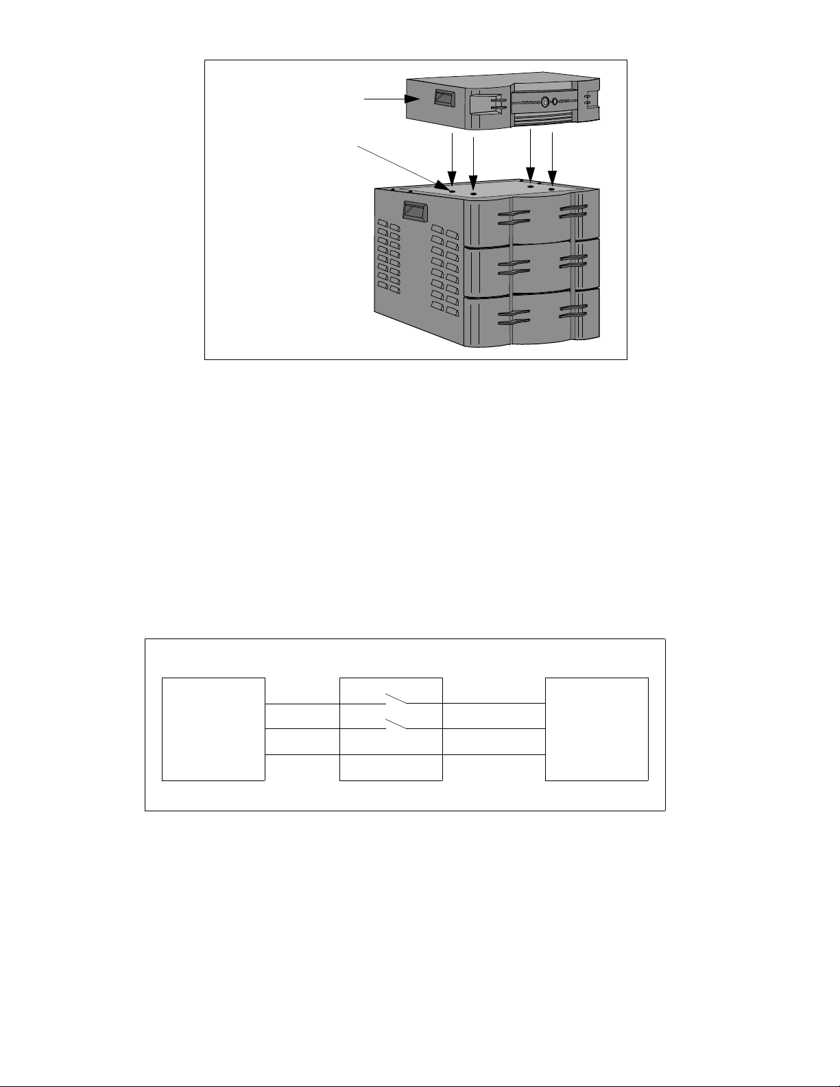
Inverter Assembly
(“feet” not shown)
Indents (4 places)
(Wire Harness not
Shown)
Figure 6. Inverter Assembly Placement
Remove power at the electricity board meter (circuit breaker panel) of the home.
Figure 7 shows a diagram of a typical home wiring scenario. Figure 8 shows a typical home wiring scenario after installation of the
Inverter Assembly wiring.
Note: The Power Inverter can serve inductive loads (flourescent lamps, ceiling and table fans), resistive loads (incandescent lamps),
and SMPS loads (television). The typical backup time with the primary battery pack at full load is approximately two (2) hours.
Caution: Connecting the Power Inverter to a branch circuit that exceeds 16 amps may
result in equipment damage.
Note: Home wiring to power the desired loads should be routed and connected to a single
branch circuit providing a maximum of 16 amps to the circuit, Wiring must be in
accordance with local electric codes and standards. Connected loads must not exceed 500
watts when the Inverter is On Battery.
Double-Pole
Switch
Electricity
Board
Meter
L
N
E
Existing Wiring
Figure 7. Typical Home Wiring Before Inverter Installation
N
L
Load
E
Page 7
Page 11

Electricity
Board
Meter
E
N
L
Double-Pole
Switch Lighting
Circuit
E
N
L
Load
Input
Output
Wiring for Power Inverter
Figure 8. Typical Home Wiring After Inverter Installation
Connect one end of the electrical cable from the double-pole switch lighting circuit in accordance with local electric codes and
standards. Connect the other end of the electrical cable to the provided IEC connector, and then to the rear panel Input connector on
the Inverter Assembly (Figures 8 and 9).
Connect one end of the electrical cable from the load in accordance with local electric codes and standards. Connect the other end of
the electrical cable to the provided IEC connector, and then to the rear panel Output connector on the Inverter Assembly (Figures 8
and 9).
Connect the wiring harness (protrudes out of the top of the Main Housing Chassis top cover) from the batteries to the rear panel
input connector of the Inverter (Figure 9) marked 24V Battery. Once the home wiring is complete and the batteries are connected
to the Inverter Assembly, turn on power at the Electricity Board Meter then at the Double-Pole Switch Lighting Circuit. The
Inverter will automatically turn on.
24V Battery
Push to Reset
INPUT
N
OUTPUT
LN
L
Page 8
Battery Wiring Output Harness
(Red and Black Wires from
Main Housing Chassis - Top)
These connectors are provided
with the Inverter Assembly
and must be installed
on to the wiring.
From Electricity Board Meter
(through Double-Pole
Switch Lighting Circuit)
Figure 9. Power Inverter Connections
To Lo ad
Input : 230V, 5A, 50Hz
Output : 230V, 5A, 50HZ
Page 12

Install Wiring Management Kit
Installation of the Wiring Management Kit consists of unpacking and inspecting the kit for signs of obvious damage, and return or
replace as necessary, and placement of the unit on the Main Housing Chassis. Secure the kit to the chassis by placing the alignment
pins (Figure 10) with the holes provided in the top of the Main Housing Chassis, and pushing straight downward until all four
retaining pins are fully seated.
Wiring Management
Kit
Holes (4 places)
Figure 10. Wiring Management Kit Installation
Alignment Pins
(4 places)
Section 4. Controls and Indicators
Please review this section thoroughly before applying power to the Power Inverter.
Inverter Controls - Controls provided on the Power Inverter consist of the holiday mode switch marked AWAY/HOME, and the
Te st / Mu t e switch, as well as a rear panel Push to Reset circuit breaker, and are defined in the following:
AWAY/HOME - (also known as the holiday mode switch) - In the HOME position, this two-position rocker switch (Figure 11) sets
the Inverter so that it will switch to battery output when there is a utility power outage.
In the AWAY position, the Inverter goes into standby mode and will not switch to battery power in the event of a power outtage.
This is to conserve the batteries. However, in this position, the Inverter will charge the batteries until a utility power failure occurs.
TEST/MUTE - In TEST mode, when ON MAINS LED is lit, on pressing this push button, the unit will do self test to determine
the state of the system. During On Battery self test it will also show the load status which can be used to find out the load capacity.
In the MUTE position (push in for 5 seconds), this push button switch silences the low battery buzzer.
Circuit Breaker Switch (Rear Panel) - When in ON MAINS mode, if the system draws more than 10A, circuit breaker will trip. To
reset the circuit breaker switch, push the switch fully inward.
Inverter Indicators - The Inverter provides light emitting diode (LED) indicators (Figure 11) to show the operational condition of
the Inverter and batteries. Indicators consist of Inverter Load Status (25%, 50%, 75%, 100%, and OVER LOAD). Other
indicators consist of: INVERTER DISABLE, ON MAINS, ON BATTERY, and FAULT). Using Table 1, determine the condition
of the Inverter and batteries.
Page 9
Page 13

25% 50% 75% 100%
OVER
LOAD
AWAY
TEST
INVERTER
DISABLEONMAINSONBATTERY FAULT
INVERTER LOAD
MUTE
HOME
Figure 11. Power Inverter Front Panel Controls and Indicators
Table 1. Power Inverter Indicators
Mode
ON LINE On Off Off Off Off Off Off Off Off Off The unit is ON-LINE.
ON LINE SELF TEST Flashing Off Off Off Off Off Off Off Off Off The unit is in ON-LINE Self-
ON BATTERY SELF
TEST
ON BATTERY Off On Off Off On Off Off Off Off 4 beeps every 22
STANDBY ENABLE Off Off Off Off Off Off Off Off Off Short beep every 5
STANDBY Off Off Off Off Off Off Off Off Off Off The unit is in STANDBY
FAULT - Off Off Off Off On On On On On Off Iverter load capacity has
FAU LT- Flashing Flashing Flashing Off Off Off Off Off Off Off The unit is in FAULT mode,
FAU LT- Off Off On Off Off Off Off Off Off Continuously On The unit is in FAULT mode,
On Mains
(green)
Flashing On Off Off On Off Off Off Off Off The unit is in ON-BATTERY
Flashing On Off Off On On Off Off Off Off The unit is in ON-BATTERY
Flashing On Off Off On On On Off Off Off The unit is in ON BATTERY
Flashing On Off Off On On On On Off Off The unit is in ON-BATTERY
Flashing On Off Off On On On On On Continuous beep for
On Battery
(yellow)
Off On Off Off On On Off Off Off 4 beeps every 22
Off On Off Off On On On Off Off 4 beeps every 22
Off On Off Off On On On On Off 4 beeps every 22
Off On Off Off On On On On On Continuous beep for
Fault
(red)
INV
Disable
(red)
25%
(green)
50%
(green)
75%
(green)
100%
(green)
Overload
(red)
Buzzer Description
Tes t mod e.
Self-Test mode, and the load
is less than 25%.
Self-Test mode, and the load
is between 25% - 50%.
Self-Test mode, and the load
is between 50% - 75%.
Self-Test mode, and the load
is more than 75% but less
than oveload limit.
first 30 seconds for a
fresh overload.
minutes
minutes
minutes
minutes
first 30 seconds of a
new overload.
seconds
The unit is in ON-BATTERY
Self-Test mode, and is in an
overload condition.
The unit is in ON-BATTERY
mode, and the load is less
than 25%.
The unit is in ON-BATTERY
mde, and the load is between
25% and 50%.
The unit is in ON-BATTERY
mode, and the load is
between 50% and 75%.
The unit is in ON BATTERY
mode; the load is between
75% and the overload limit.
The unit is in ON-BATTERY
mode, and is in overload
condition (see NOTE below).
The unit is shut down due to a
LOW BATTERY.
mode, and is not powering
the load.
been exceeded (see NOTE
below).
contact APC Technical
Support.
contact APC Technical
Support.
Page 10
Page 14

Mode
FAU LT- On Flashing Flashing Off Off Off Off Off Off Chirps every 2.5
BATTERY
DISCONNECTED
OVER TEMP ONBATTERY
OVER TEMP ONLINE
ON LINE On Off Off On Off Off Off Off Off Off The unit is in ON-LINE, but
ON LINE SELF TEST Flashing Off Off On Off Off Off Off Off Off The unit is in ON-LINE Self-
ON BATTERY SELF
TEST
ON BATTERY Low
Battery Warning
ON BATTERY Low
Battery Warning
ON BATTERY Low
Battery Warning
ON BATTERY Low
Battery Warning
ON BATTERY Low
Battery Warning
On Mains
(green)
Flashing On Off On On Off Off Off Off Off The unit is ON-BATTERY-
On Battery
(yellow)
On Off Flashing Off Off Off Off Off Off Chirp every 2 seconds The unit is ON-LINE mode;
Off Off 4 flashes
On Off 4 flashes
Off On Off Off On Off Off Off Off Constant Beeping,
Off On Off Off On On Off Off Off Constant Beeping,
Off On Off Off On On On Off Off Constant Beeping,
Off On Off Off On On On On Off Constant Beeping,
Off On Off Off On On On On On Constant Beeping,
Fault
(red)
every 2
second
every 2
second
INV
Disable
(red)
25%
(green)
Off Off Off Off Off Off Continuously On The unit is in FAULT mode
Off Off Off Off Off Off Off The unit is in ON-LINE mode,
50%
(green)
75%
(green)
100%
(green)
Overload
(red)
Buzzer Description
seconds; sound is
mutable through the
front panel TEST/
MUTE push button.
Can be muted through
fron panel TEST/
MUTE push button.
Can be muted through
front panel TEST/
MUTE push button.
Can be muted through
front panel TEST/
MUTE push button.
Can be muted through
front panel TEST/
MUTE push button.
Can be muted through
front panel push
TEST/MUTE button.
The unit is in FAULT mode,
contact APC Technical
Support.
battery is disconnected.
due to over- temperature
condition.
but the charger is switched off
due to over- temperature.
the inverter is disabled and
the unit will not go ON
BATTERY during a power
failure.
Test mode, but the inverter is
disabled and the unit will not
go ON-BATTERY during a
power failure.
Self-Test but the inverter is
disabled and the unit will not
go ON-BATTERY during a
power failure.
Load is less than 25%.
Load is between 25% and
50%.
Load is between 50% and
75%.
Load is between 75% and
Overload limit.
Load is more than overlaod
limit.
NOTE: In the case of a sustained overload, the Inverter will be turned off automatically after one
minute, and will wait in the fault state for a minute. After that, it will restart again. If the overload
still persists, the Inverter will be turned off again after one minute, and will wait in fault state for one
minute and restart again. In the same way, it will try for three restarts. If the overload still persists, it
will stay in fault state permanently until the unit is restarted with push button. If the time interval
between two consecutive overloads is more than 5 mins, then the latest overload is considered as a
fresh overload and three restart cycle will begin again.
Page 11
Page 15

Section 5. Troubleshooting
Note: If the Power Inverter causes interference with a television while ON-BATTERY,
move the television at least 3 feet away from the Inverter.
Use the information provided in Tables 1 and 2 to diagnos Power Inverter problems. If the problem cannot be resolved using the
information provided in this manual, contact APC Technical Support.
Table 2. Power Inverter Troubleshooting
Problem Cause Corrective Action
Inverter fails to operate when
mains power is turned on, or
during a utility power failure.
Computer load reboots when
inverter switches to ON
BATTERY.
Inverter faults. Inverter drops the load.
Disconnected battery.
Power is off at the Mains.
Inverter HOME/AWAY switch in
the AWAY position.
Dead batteries.
Inverter rear panel Push to Reset
circuit breaker has tripped.
Improper wiring installation or
loose connection.
Inverter transfer time too slow for
computer load.
Ensure batteries are connected as defined in this
manual.
Turn on power at the Mains.
Set switch to the HOME position.
Inverter failed to charge batteries, or batteries were
allowed to completely discharge. Replace batteries. If
replacing the batteries does not fix the problem,
contact APC Technical Support.
Reset the circuit breaker by pushing it fully inward
until it stops; release the circuit breaker.
Ensure wiring is as described earlier in this manual,
and that all connections are secure.
For computer-type loads, a separate battery back-up
(UPS) should be used, as the 60 millisecond transfer
time is inadequate, and will cause the computer to
reboot.
Inverter may have an internal failure. If this happens,
the unit can be disconnected from the mains by
completion of a Manual Bypass (see Manual
Bypass).
Inverter is overloaded.
Manual Bypass - In the event of an Inverter failure or dead battery condition, the Inverter can be disconnected from the mains and
power restored to the circuit by completing a Manual Bypass (Figure 12) of the Inverter, as follows:
Remove the Wiring Management Kit from the Inverter. Disconnect all wires connected at the Inverter rear panel. Connect the wire
from the Input socket to the wire from the Output socket.
Turn off some loads connected to the Inverter until
the OVER LOAD LED is no longer lit
Page 12
Page 16

Push to Reset
INPUT
N
OUTPUT
LN
L
Input : 230V, 5A, 50Hz
Output : 230V, 5A, 50HZ
Disconnect from
Inverter
Connect Both Wires
Completed Bypass Connection
Figure 12. Power Inverter Bypass Connection
Preventative Maintenance - Preventative maintenance consists of inspecting the batteries for cracks and/or leakage, and checking battery fluid levels and
filling the batteries (every 120 days), using the criteria and methods as defined earlier in this manual. Dust the unit with a dry cloth. Do not use liquids
when cleaning.
Page 13
Page 17

Specifications
Input
Characteristics
Output
Characteristics
Surge
Protection
Environmental Ambient Operating Temperature 0-45 degrees C
Physical Input Line IEC socket
Batteries Type Two 12 V, 70 Amp-Hour
Table 3. APC Power Inverter Technical Specifications
Item Specification
Nominal Voltage 230 V
Rated Voltage 230 V
Frequency 47-53 Hz
Nominal Rated Current 3.47 A
Input Circuit Breaker Rating 10 A
Input Voltage Window for Utility Operation 100 - 265 VAC
Voltage (on Mains) 100 - 265 VAC
Voltage (on battery) 210 - 240 VAC
Rated VA 800 VA
Rated Watts 500 W
Nominal Rated Current 3.47 A
Overload Indicated ON BATTERY >100%
Shutdown due to OVERLOAD > 100% after 60 seconds (see Table 1 and following note)
Frequency (ON BATTERY) 50 Hz +/- 1%
Built-in Surge Protection Protects the load from surges and spikes..
Humidity 95 % Relative humidity, non-condensing
Altitude 3000 m
Outlet Receptacles IEC socket
Dimensions - Unit (h) x (w) x (d) Main Housing Chassis: 51.2 x 47.5 x 43.0 cm
Weight Main Housing Chassis: 18 kg
Shipping Weight Main Housing Chassis: 20.5 kg
Typical Runtime Approximately 120 minutes
Typical Load Set Up Set-up A = 5 fans, 4 tube lights
Runtime at 500 W Approximately 120 minutes
Typical Recharge Time (for a 90% Charge
Following a 50% Discharge)
AC Input Voltage Range for Charging 100 - 265 V
Inverter Assembly: 13.0 x 50.6 x 29.3 cm
Battery: 27.94 x 17.78 x 41.27 cm
Inverter Assembly: 13.5 kg
Battery: 28 kg
Inverter Assembly: 14.5 kg
Battery: XX kg (each)
Set-up B = 4 fans, 4 tube lights, and 1 TV
8-10 Hours
Page 14
Page 18

Warranty
APC warrants its products to be free from defects in materials and workmanship under normal use and service for 2 years for the Inverter,
and 2 years for the Batteries to the original purchaser. Its obligation under this warranty is limited to repairing or replacing, at its sole
option, any such defective products. To obtain service under warranty you must obtain a Return Material Authorization (RMA) number
from APC Technical Support or an APC Service Center. The defective unit must be returned with an RMA number, with transportation
charges prepaid and it must be accompanied by a brief description of the problem and proof of date and place of purchase. This warranty
applies only to the original purchaser.
Contact Information
APC Corporate Office
132 Fairgrounds Road
West Kingston, RI 02892, USA
Tel: 401-789-0204
APC Corporate Office (India)
27 Lavelle Road
Bangalore 560 001
www.apc.com
Toll Free Helpline: 1600 444 272 and 1600 444 877
email: indiainfo@apc.com
Technical Webchat: www.apc.com/in
Page 15/Page 16 blank
 Loading...