

Page 1
User Guide - Back-UPS
Back-UPS
bu127a
Battery Back-up + Surge Protection
AVR
Check Batt ery
bu128a
Modem/Phone/
FAX
Wall Outlet
Data Port
8 A 5 A
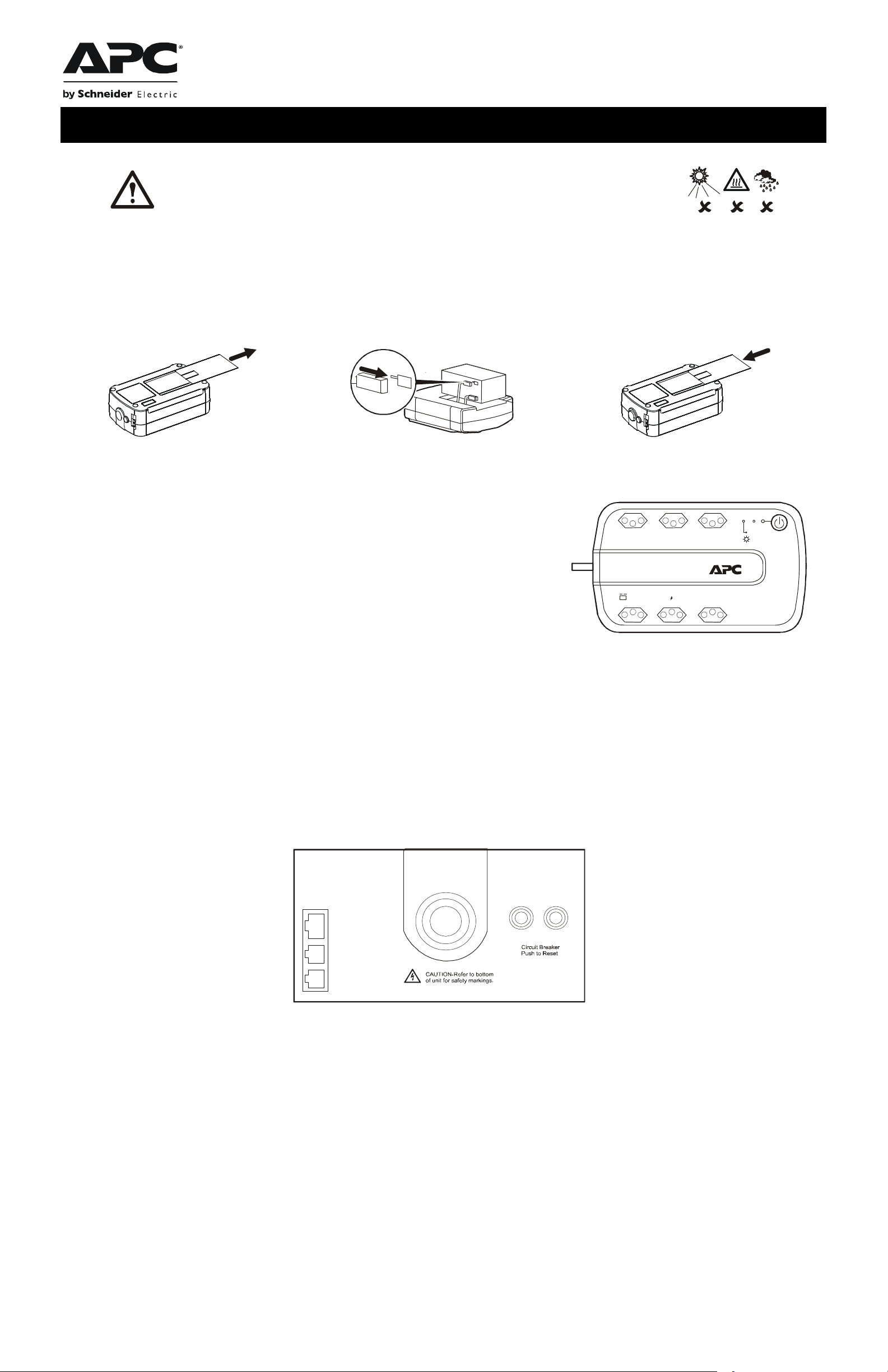
This unit is intended for indoor use only.
Do not operate this unit in direct sunli ght, in contact with fluids, or where there is excessive dust or humidity.
Connect the Back-UPS power cord directly to a wall outle t. Do not use a surge protector or an extension cord.
BE600N-BR
Connect the Battery
The Back-UPS is sh ipped with one battery ca ble disconnected. Re move the “Stop! Connect the Battery” label that covers the terminals. Prior to conne cting any
equipment to the unit, connect the battery cable to the unused battery terminal. Smal l sparks may occur when the batt ery cable is connected to the battery terminal.
®
Press the battery compartmen t co ver
release tab located on the rear side of the unit.
Slide the battery cover off.
Connect the battery cable securel y to the battery
terminal.
Rei nstall the ba tt er y co m p a rt ment cover. Be su re that
the release tab locks into pl ace.
bu064b
bu114a
Connect Equipment
Battery Back-up + Surge Protection outlets
Outlets provide protection to connected equipment when the Back-UPS is turned ON and
connected to utility power.
Outlets receive power fro m the Back-UPS for a limited period of time when a power outage,
or brownout condition occur s.
Outlets provide protection from power surges or spikes.
Connect a computer, monitor and other peripheral devices to the outlets.
Connect a Computer
If utilizing PowerChute software, connect the supplied data cable to the data port on the rear side of the Back-UPS and to the USB port on the
computer.
PowerChute software provides automatic file saving and shutdown of a connected computer during a sustained power outage.
bu066b
Overload
PowerChute software is an option that can be purchased along with a data cable through the APC Web site, www.apc.com.
Connect a Modem/Phone/FAX
1. Use a standard telephone cable to connect the Back-UPS Wall Outlet port to a telephone wall jack.
2. Use a standard telephone cable to connect the Back-UPS Modem/Phone/FAX port to a modem or FAX machine.
1
Page 2

Turn On the Back-UPS
Press the Po wer ON button located on the top of the Back-UP S. The green LED will illuminate and a sing le short beep will be audible indicating that
the Back-UPS is providing protection for connected equipment.
The Back-UPS battery charge s fully during the first eight hours while connected to utility power. The Back-UPS battery will cha rge while the BackUPS is switched ON or OFF. Do not expect full battery run capability during the initial charge time.
Install PowerChute Software
Install the optional PowerChu te CD in the computer and follow the prompts to install the software.
Status Indicators
Status LED Indica tor Audible Indi ca to r On Audible Indicator Off
Power On
The Back-UPS is su pplying utility power to
connected equipment.
The green LED illuminates. N/A N/A
On Battery
Back-UPS supplying battery
power to battery back-up outlets.
Low Batter y warning
The Back-UPS is su pplying battery power
to the ba ttery back-up outlets and the b attery
is near a total discharge state.
Check Battery
• The battery is dis connected.
• The battery needs to be charged, or replaced.
Overload Shutdown
While on battery power an overload condition
has occurred in one or more of the batt ery
back-up outlet s while the Back-UPS is operati ng
on battery power.
AVR When the AVR feature is activated
Sleep Mode
While on battery powe r the battery is
completely discharged. The Back-UPS will
“awaken” once utility power is restored.
The green LED illuminates.The
LED is not illuminated during the
beeps.
The green LED illuminates with
rapid green flashes.
The red LED flashes. Constant tone Back-UPS is turned Off.
The red LED illum inates. Constant tone Ba ck- U PS is turned Off.
the amber LED illuminates .
N/A
Back-UPS beeps four time s every
30 seconds.
The Back-UPS emits rapid beep ing,
(every 1/2 second).
N/A N/A
The Back-UPS beeps once every
four s e c onds.
Beeping stops when power transfers
back to utili ty power or t he Back -UPS is
turned OFF.
The beeping s tops when power transfers
back to utili ty power or t he Back -UPS is
turned OFF.
The beeping stops when:
• Utility power is restored
• If utility power is not restored within
32 seconds
• The Back-UPS is turned OFF
Voltage Sensitivity Adjustment (optional)
The Back-UPS detects and reacts to line voltage distortions by transfer ring to battery back-up power to protect connecte d equipment. In situations
where either the Back-UPS or the connected equipment is too sensitive for the input voltage level it is necessary to adjust the transfer voltage.
1. Connect the Back-UPS to a wall outlet. The Back-UPS will be in Standby mode, no indicators will be illuminated.
2. Press and hold the Power On button for 10 seconds. The red LED flashes, to indicate that the Back-UPS is in Program mode.
3. The green or red LEDs will flash to indic ate the current sensitivity l evel. Refer to the table for an explanation of the transf e r voltage sensitivity
levels.
4. To select LOW sensitivity , pr ess and hold the Power On button until the green LED flashes.
5. To select MEDIUM sensitivity, press and hold the Power On button until the red LED flashes.
6. To select HIGH sensitivity, press and hold the Power On button until the green and red LEDs flash alternately.
7. To exit Program mode wait five seconds and all LED indicators will extinquish. Program mode is no longer active.
LED Flashes Sensitivity Se tt ing Input Voltage Range Recommended Use
Green LOW 115 Vac: 88 Vac to 143 Vac
220 Vac: 176 Vac to 264 Vac
Red MEDIUM (factory default) 115 Vac: 88 Vac to 143 V ac
220 Vac: 176 Vac to 264 Vac
Alternating Green/Red HIGH 115 Vac: 96 Vac to 137 V ac
220 Vac: 192 Vac to 252 Vac
Input voltage is extremely low or extremely high. Not
recommended for computers.
Use when the Back-UPS frequently switches to battery
operation.
Use when connected equipm ent is sensitive to voltage
fluctuations.
2
Page 3

Specifications
b
Input
Output
Bivolt
Circuit Breaker Ratings
Protection and Filter
Battery
Physical
Voltage 115 Vac or 220 Vac Nominal
Frequency 60 Hz + 3
Brownout Transfers 115 Vac: 88 Vac Typical, 220 Vac: 176 Vac Typical
Over-volt age Transfer 115 Vac: 143 Vac Typical, 220 Vac: 264 Vac Typical
UPS Capacity (6 outlets) 600 VA, 360 W
Voltage - On Battery 115 Vac +6%, -10% (step-approximated sine wave)
Frequency - On Battery 60 Hz +
Trans f er Time 5 ms Typical, 8 ms maximum
Automatic Bivolt 115 Vac: 88-143 Vac, 220 Vac: 176-264 Vac
115 Vac: 8 A, 220 Vac: 5 A
AC Surge Protection Full time, 365 jou les
Modem/Phone/FAX Surge Protection Single line (2-wire)
EMI/RFI Filter F u ll time
AC Input Circuit break er rese t
Type Sealed, maintenance-free, lead acid
Average Life 2 - 4 years depending on the number of discharge cycles and environmental
temperature
Net Weight 8 kg (18 lb)
Dimensions H x W x D
10 cm x 34 cm x 21 cm
4 in x 10 in x 7 in
1
Troubleshooting
Problem and Possible Cause Solution
The Back-UPS will not turn on
The Back-UPS has not been turned on. Press the Power on button.
The Back-UPS is not connected to utili ty power, ther e is no utility power
available at the wall outlet, or the utility power is experiencing a brownout or over
voltage condition.
Connected equipment loses power
A Back-UPS overload condition has occurred. Remove all nonessential equipment connected to t he outlets. One at a ti me reconnect
The Back-UPS battery is completely discharged. Connect the Back-UP S to utility power and allow the battery to recharge for eight
PowerChute software has performed a shutdown due to a power failure. The Back-UPS is operating normally.
The Back-UPS may require service. Contact APC Technical Support for more in depth troubleshooting.
The Back-UPS is on, the Check Battery LED flashes and the unit emits a constant tone
The battery is disconnected. Refer to the Conn ect the Battery se ction in this guide.
The Power On LED is illuminated and the Back-UPS beeps four times every 30 seconds
The Back-UPS is ope rating on battery power. The Back-UPS is operating norm ally on battery power. At this point the user should
Make sure the power cord is securely connected to the wall outl et, and that there is
utility power ava ilable at the wall outlet.Where applicable, check that the wall outlet
is switched on.
equipment to the Back-UPS.
hours.
save all open files, and shutdown the computer. When utility powe r is restored the
battery will rechar ge.
The Back-UPS has an inadequate battery runtime
The battery is not fully charged. Leave the Back-UPS connected to utility power for eight hours while the batte r y
charges to full capacity.
The battery life cycle is near completi on. As the battery ages the run time capability dec r ea ses. To order a replacement battery
contact APC at www.apc.com.
Replace the Battery
Deliver used batteries to a CASC facility.
Request that CASC replace the battery with an APC approved battery.
P
Pb
Contact APC through the APC Web site www.apc.com, for the location of the nearest
CASC facility.
Warranty
The standard warr anty is 2 years from the date of purchase. APC standard procedure is to replace the original unit with a factory reconditioned unit. Customers who
must have the origi nal unit ba ck due to as signed asset tags and set depreciation schedules must decla r e such a need at first contact with AP C Technical Support. APC
will ship the replacement unit once the defe ctive unit is received by the repair department or cross- ship upon the provision of a valid credit card number. The
customer pays for shi pping to APC, and APC pays ground fre ight transportation costs back to the customer.
3
Page 4

Service
If the unit requires se rvice do not return it to the dealer. F ollow these steps:
1. Review the probl em s discussed in Troubleshooting in this manual to eliminate common problems.
2. If the problem persis ts , contact APC Customer Support through the APC Web site, www .apc.com.
a. Note the model number of the unit, the serial number located on the rear side of the unit, and the date purchased. If you call APC Customer
Support, a technician will ask you to des cribe the problem and attempt to solv e it over the phone. If this is not possible, the technician will issue a
Returned Material Authorization Number (RMA#).
b. If th e UPS is unde r warra nty, repairs are free.
c. Procedures for servicing or returning products ma y vary internationally. Refer to the APC Web site for country specific instructions.
3. Pack the unit in its original packaging. If this is not available, refer to www .apc.com for information about obtai ning a new set.
a. Pack the unit properly to avoid damage in transit. Never use Styrofoam beads for packaging. Damage sustained in trans it is not covered under
warranty.
b. Always DISCONNECT THE BA TTE RY before shipping in compliance with U.S. Department of Transportation (DOT) and IATA
regulations. The battery may remain in the UPS.
4. Mark the RMA# on the outside of the package.
5. Return the UPS by insured, prepaid carrier to the address given to you by Customer Sup port.
Contact
APC We b site, www.apc.com
Telephone support: Toll Free 0 800 555 272; Brazil 11 4689 8600
© 2010 APC by Schneider Electric. APC, the APC logo are owned by Schneider Electric Indust ries S.A.S., American Power
Conversion Corporation, or their affiliated companie s. All other trademarks are property of their respective owners.
990-3795B
04/2010
 Loading...