

AO Smith GVR50-201, GVR50-200, GVR40-201, GVR40-200 Owner’s Manual
Installation Instructions and Use & Care Guide
A.O.Smith
FVIR GAS WATER HEATER
(FLAMMABLE VAPOR IGNITION RESISTANT)
FOR SPACEHEATINGAND POTABLEWATERHEATINGONLY.
NOT FOR USEIN MOBILEHOMES.
This water heater complies with ANSI Z21.10.1-current
edition regarding the accidental or unintended ignition of
flammable vapors, such as those emitted by gasoline.
Read and understand instruction
manual and safety messages
before installing, operating or
servicing this water heater.
Failure to follow instructions and
safety messages could result in
death or serious injury.
Instruction manual must remain
with water heater.
Safety Instructions • Care and Maintenance
• Installation • Troubleshooting
• Operation • Parts List
INSTALLER:
• AFFIX THESE INSTRUCTIONS TO OR ADJACENT
TO THE WATER HEATER.
OWNER:
• RETAIN THESE INSTRUCTIONS AND WARRANTY
FOR FUTURE REFERENCE. RETAIN THE
ORIGINAL RECEIPT AS PROOF OF PURCHASE.
WARNING: Gas leaks can not always be detected by
smell.
Gas suppliers recommend that you use a gas detector
approved by UL or CSA.
For more information, contact the your gas supplier.
If a gas leak is detected, follow the "WHAT TO DO IF YOU
SMELL GAS" instructions.
For Your Safety
AN ODORANT IS ADDED TO THE GAS USED
BY THIS WATER HEATER.
WARNING: If the information in these
instructions is not followed exactly, a fire
or explosion may result causing property
damage, personal injury or death.
m Do not store or use gasoline or other
flammable vapors and liquids in the
vicinity of this or any other appliance.
WHAT TO DO IF YOU SMELL GAS
• Do not try to light any appliance.
• Do not touch any electrical switch;
do not use any phone in your
building.
• Immediately call your gas supplier
from a neighbor's phone. Follow the
gas supplier's instructions.
• If you cannot reach your gas
supplier, call the fire department.
Installation and service must be
performed by a qualified installer,
service agency or the gas supplier.
ALL TECHNICAL AND WARRANTY QUESTIONS: SHOULD BE DIRECTED TO THE LOCAL DEALER FROM WHOM THE WATER HEATERWAS PURCHASED.
IF YOU ARE UNSUCCESSFU L, CONTACT RESIDENTIAL TECHNICALASSISTANCE AT 1-800-527-1953 OR WWW.HOTWATER.COM.
PRINTED INTHE U.S.A 0108 PARTNO. 186487-001

Water Heater Safety .......................................................................................................................................................................... 1 -2
Safe Installation, Use and Service ...................................................................................................................................................... 3
Safety Precautions ............................................................................................................................................................................ 3-4
Typical Installation ............................................................................................................................................................................... 5
Installing you Gas Water Heater ...................................................................................................................................................... 6-8
Important Information About Your Water Heater ...................................................................................................................... 6
Consumer Information ............................................................................................................................................................. 6
Consumer Responsibilities ...................................................................................................................................................... 6
Unpacking the Water Heater ................................................................................................................................................... 6
Location Requirements ............................................................................................................................................................ 7
Site Locations .......................................................................................................................................................................... 7
Clearances and Accessibility ................................................................................................................................................... 8
State of California .................................................................................................................................................................... 8
Gas Supply ....................................................................................................................................................................................... 9-10
Gas Requirements .................................................................................................................................................................... 9
Gas Piping ............................................................................................................................................................................... 9
Gas Pressure ........................................................................................................................................................................... 9
Gas Pressure Testing ............................................................................................................................................................... 9
Combustion Air and Ventilation .................................................................................................................................................... 11-15
Water System Piping ..................................................................................................................................................................... 15-18
Important Information About this Water Heater .............................................................................................................................. 19
Operating Your Water Heater ....................................................................................................................................................... 20-25
Maintenance of Your Water Heater .............................................................................................................................................. 25-29
Troubleshooting Checklist ........................................................................................................................................................... 29-30
Pilot Light Troubleshooting Flowchart ............................................................................................................................................ 31
Repair Parts Illustration ..................................................................................................................................................................... 32
Notes ................................................................................................................................................................................................... 34
Warranty .......................................................................................................................................................................................... 35-36
LP Gas Only ........................................................................................................................................................................... 10
Unconfined Space ................................................................................................................................................................... 11
Confined Space ...................................................................................................................................................................... 11
All Air from Inside the Building ............................................................................................................................................... 12
All Air from Outdoors .............................................................................................................................................................. 12
Louvers and Grilles ........................................................................................................................................................... 12-13
Vent Pipe System .................................................................................................................................................................. 13
Draft Hood Installation ...................................................................................................................................................... 13-14
Vent Pipe Size ....................................................................................................................................................................... 14
Vent Connectors .................................................................................................................................................................... 14
Chimney Connection .............................................................................................................................................................. 14
Vertical Exhaust Gas Vent ................................................................................................................................................ 14-15
Piping Installation .............................................................................................................................................................. 15-16
Closed System/Thermal Expansion ....................................................................................................................................... 16
Temperature & Pressure Relief Valve .................................................................................................................................... 17
T&P Relief Valve and Pipe Installation .................................................................................................................................. 17
Combination Space Heating/Potable Water System ........................................................................................................ 17-18
Solar Installation .................................................................................................................................................................... 18
White-Rodgers Gas Valve/Thernostat - Lighting Instructions ................................................................................................ 20
RobertShaw Gas Valve/Thermostat - Lighting Instructions .................................................................................................. 21
Checking the Draft ................................................................................................................................................................. 21
Burner Flames ....................................................................................................................................................................... 22
Emergency Shutdown ............................................................................................................................................................ 22
Water Temperature Regulation ......................................................................................................................................... 22-23
Operational Conditions ..................................................................................................................................................... 23-24
Routine Preventive Maintenance ........................................................................................................................................... 24
Temperature and Pressure Relief Valve ................................................................................................................................ 25
Replacement Parts ................................................................................................................................................................ 25
Removing the Burner from the Manifold/Burner Assembly .............................................................................................. 25-26
Replacing the Thermocouple ................................................................................................................................................. 26
Replacing the Pilot/Pilot Tube Assembly ............................................................................................................................... 26
External Inspection & Cleaning of the Base-Ring Filter ........................................................................................................ 27
Cleaning the Combustion Chamber and Flame-arrestor ....................................................................................................... 27
Replacing the Manifold Burner/Assembly ......................................................................................................................... 27-28
Piezoelectric Igniter System .................................................................................................................................................. 28
Testing the Igniter System ..................................................................................................................................................... 28
Removing and Replacing the Gas Control Valve/Thermostat .......................................................................................... 28-29
FVIR System Operational Checklist ...................................................................................................................................... 29
Listed Parts Kits and Illustrations............................................................................................................................................ 33
Your safety and the safety of others is extremely important in the installation, use and servicing of this water heater.
Many safety-related messages and instructions have been provided in this manual and on your water heater to warn you and
others of a potential hazard. Read and obey all safety messages and instructions throughout this manual. It is very important
that the meaning of each safety message is understood by you and others who install, use or service this water heater.
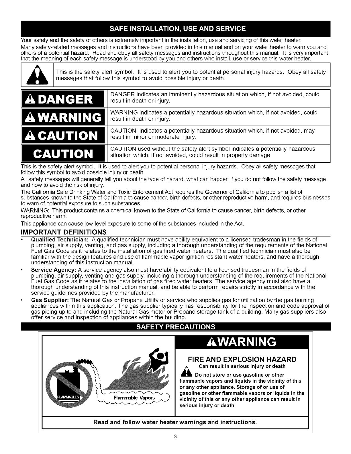
[ _ [This is the safety alert symbol. It is used to alert you to potential personal injury hazards. Obey all safety
messages that follow this symbol to avoid possible injury or death.
DANGER indicates an imminently hazardous situation which, if not avoided, could
result in death or injury.
WARNING indicates a potentially hazardous situation which, if not avoided, could
result in death or injury.
CAUTION indicates a potentially hazardous situation which, if not avoided, may
result in minor or moderate injury.
CAUTION used without the safety alert symbol indicates a potentially hazardous
situation which, if not avoided, could result in property damage
This is the safety alert symbol. It is used to alert you to potential personal injury hazards. Obey all safety messages that
follow this symbol to avoid possible injury or death.
All safety messages will generally tell you about the type of hazard, what can happen if you do not follow the safety message
and how to avoid the risk of injury.
The California Safe Drinking Water and Toxic Enforcement Act requires the Governor of California to publish a list of
substances known to the State of California to cause cancer, birth defects, or other reproductive harm, and requires businesses
to warn of potential exposure to such substances.
WARNING: This product contains a chemical known to the State of California to cause cancer, birth defects, or other
reproductive harm.
This appliance can cause low-level exposure to some of the substances included inthe Act.
IMPORTANT DEFINITIONS
• Qualified Technician: A qualified technician must have ability equivalent to a licensed tradesman in the fields of
plumbing, air supply, venting, and gas supply, including a thorough understanding of the requirements of the National
Fuel Gas Code as it relates to the installation of gas fired water heaters. The qualified technician must also be
familiar with the design features and use of flammable vapor ignition resistant water heaters, and have a thorough
understanding of this instruction manual.
• Service Agency: A service agency also must have ability equivalent to a licensed tradesman in the fields of
plumbing, air supply, venting and gas supply, including a thorough understanding of the requirements of the National
Fuel Gas Code as it relates to the installation of gas fired water heaters. The service agency must also have a
thorough understanding of this instruction manual, and be able to perform repairs strictly in accordance with the
service guidelines provided by the manufacturer.
• Gas Supplier: The Natural Gas or Propane Utility or service who supplies gas for utilization by the gas burning
appliances within this application. The gas supplier typically has responsibility for the inspection and code approval of
gas piping up to and including the Natural Gas meter or Propane storage tank of a building. Many gas suppliers also
offer service and inspection of appliances within the building.
A • • A
FIRE AND EXPLOSION HAZARD
Can result in serious injuryor death
Do not store or use gasolineor other
flammable vaporsand liquids in the vicinity of this
or any other appliance. Storage of or useof
Flarrm_ble Vapors
Read and follow water heater warnings and instructions.
gasolineor otherflammable vapors or liquids in the
vicinity ofthis or any other appliance can resultin
serious injuryor death.
3
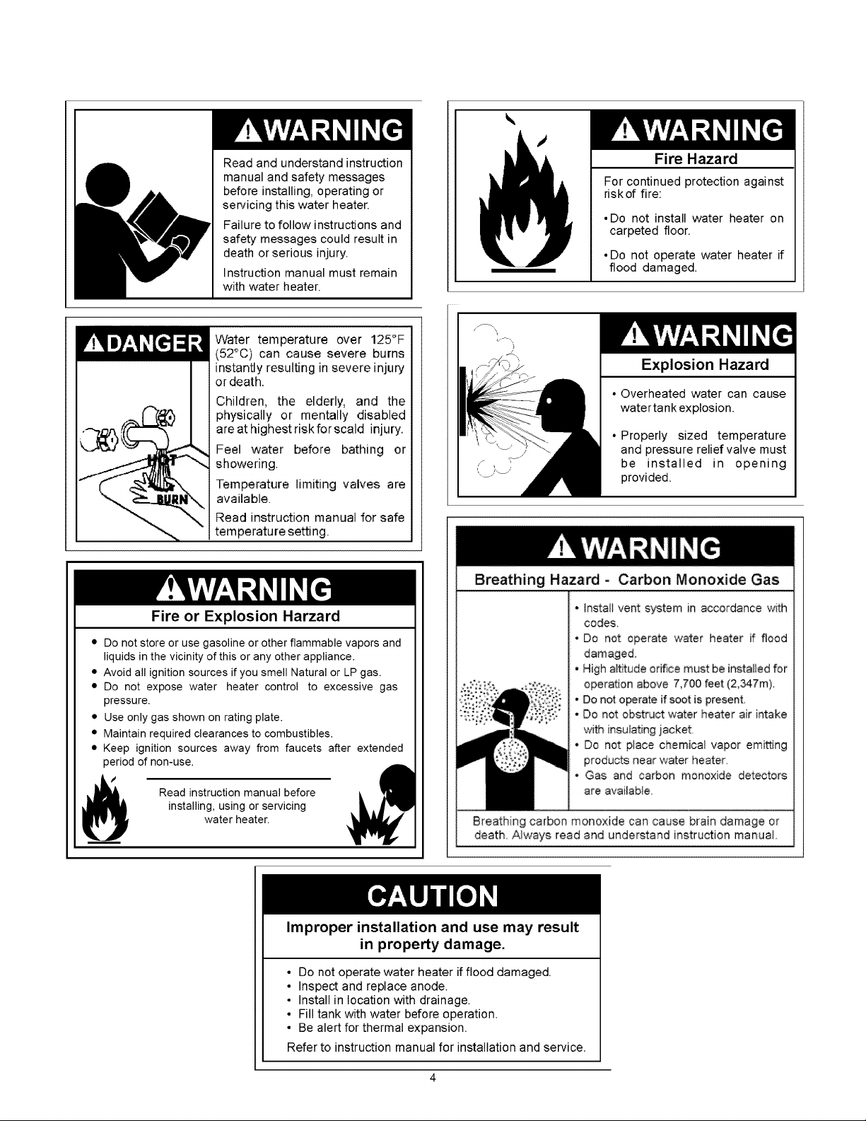
Read and understand instruction
manual and safety messages
before installing, operating or
servicing this water heater.
Failure to follow instructions and
safety messages could result in
death or serious injury.
Instruction manual must remain
with water heater.
Water temperature over 125°F
(52°C) can cause severe burns
instantly resulting in severe injury
or death,
Children, the elderly, and the
physically or mentally disabled
are at highest riskforscald injury,
Feel water before bathing or
showering.
Temperature limiting valves are
available.
Read instruction manual for safe
temperature setting.
Fire Hazard
For continued protection against
riskof fire:
• Do not install water heater on
carpeted floor.
• Do not operate water heater if
flood damaged.
Explosion Hazard
• Overheated water can cause
watertank explosion.
• Properly sized temperature
and pressure relief valve must
be installed in opening
provided.
Fire or Explosion Harzard
• Do not store or use gasoline or other flammable vapors and
liquids in the vicinity of this or any other appliance.
• Avoid all ignition sources if you smell Natural or LP gas.
• Do not expose water heater control to excessive gas
pressure.
• Use only gas shown on rating plate.
• Maintain required clearances to combustibles.
• Keep ignition sources away from faucets after extended
period of non-use.
installing, using or servicing
Read instruction manual before
water heater.
Improper installation and use may result
in property damage.
• Do not operate water heater if flood damaged.
• Inspect and replace anode.
• Install in location with drainage.
• Fill tank with water before operation.
• Be alert for thermal expansion.
Refer to instruction manual for installation and service.
Breathing Hazard - Carbon Monoxide Gas
- Instait vent system in accordance with
codes.
• Do not operate w_er heater if flood
damaged.
- High altitude orifice must be installed for
operation above 7,700 feet (2,347m).
. Do not o_rate if soot is present.
• Do not obstruct water heater air intake
with ineullating iacket.
• Do not place chemical vapor cruising
products near water heater,
• Gas and carbon monoxide detectors
are avai{ab_e_
Breathing carbon monoxide can cause brain damage or
death Always read and understand instruction manual
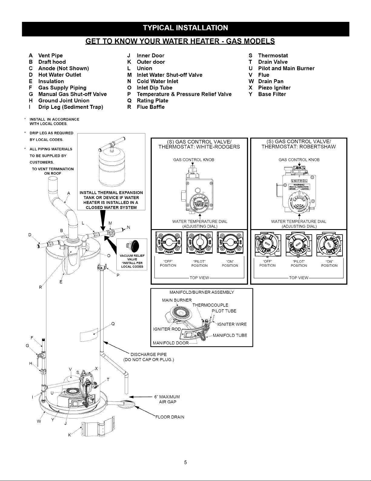
GET TO KNOW YOUR WATER HEATER - GAS MODELS
A Vent Pipe
B Draft hood
C Anode (Not Shown)
D Hot Water Outlet
E Insulation
F Gas Supply Piping
G Manual Gas Shut-off Valve
H Ground Joint Union
I Drip Leg (Sediment Trap)
INSTALL IN ACCORDANCE
WITH LOCAL CODES.
DRIP LEG AS REQUIRED
BY LOCAL CODES.
ALL PIPING MATERIALS
TO BE SUPPLIED BY
CUSTOMERS.
TO VENT TERMINATION
ON ROOF
3
i .... ' A
INSTALL THERMAL EXPANSION
TANK OR DEVICE IF WATER
HEATER IS INSTALLED IN A
CLOSED WATER SYSTEM
B L
J Inner Door S Thermostat
K Outer door T Drain Valve
L Union U Pilot and Main Burner
M Inlet Water Shut-off Valve V Flue
N Cold Water Inlet W Drain Pan
O Inlet Dip Tube X Piezo Igniter
P Temperature & Pressure Relief Valve Y Base Filter
Q Rating Plate
R Flue Baffle
(S) GAS CONTROL VALVE/
THERMOSTAT: WHITE-RODGERS
GAS CONTROL KNOB
WATER TEMPERATURE DIAL
f
(ADJUSTING DIAL)
(S) GAS CONTROL VALVE/
THERMOSTAT: ROBERTSHAW
GAS CONTROL KNOB
WATER TEMPERATURE DIAL
(ADJUSTING DIAL)
6::::::::......
J /
R_ E
F _\\ ...... j/
\,
\
\\
\
H\
I /"/
"OFF .... PILOT .... ON"
POSITION POSITION POSITION
TOP VIEW
MANIFOLD/BURNERASSEMBLY
MAIN BURNER
,,
THERMOCOUPLE
PILOTTUBE
zQ
/
---MANIFOLDTUBE
MANIFOLD DOOR
DlSCHARGEPIPE
(DO NOTCAPORPLUG.)
"OFF"
POSITION
'PILOT"
POSITION
TOP VIEW
'ON"
POSITION
w j
Important Information About This Water Heater
This gas water heater was manufactured to voluntary
safety standards to reduce the likelihood of a flammable
vapor ignition incident. New technology used in meeting
these standards makes this product more sensitive to
installation errors or improper installation environments.
Please review the Installation Checklist found at the end of
the installation instructions section and make any required
installation upgrades or changes.
Consumer Information
This water heater is design-certified by CSA International
as a Category I, non-direct vented water heater which
takes its combustion air either from the installation area or
from air ducted to the unit from the outside.
This water heater must be installed according to all local
and state codes or, in the absence of local and state
codes, the "National Fuel Gas Code", ANSI Z223.1(NFPA
54)-current edition. This is available from the following:
CSA America, Inc.
8501 East Pleasant Valley Road
Cleveland, OH 44131
National Fire Protection Agency
1 Batterymarch Park
Quincy, MA 02269
Check your phone listings for the local authorities having
jurisdiction over your installation.
Consumer Responsibilities
Unpacking the Water Heater
Excessive Weight Hazard
Usetwo or morepeopleto moveandinstallthewaterheater.
Failureto doso can resultin injury(includingbackinjury).
IMPORTANT: Do not remove any permanent instructions,
labels, or the data label from either the outside of the
water heater or on the inside of water heater panels.
• Remove exterior packaging and place installation com-
ponents aside.
• Inspect all parts for damage prior to installation and
start-up.
• Completely read all instructions before attempting to
assemble and install this product.
• After installation, dispose of/recycle all packaging
materials.
This manual has been prepared to acquaint you with the
installation, operation, and maintenance of your gas water
heater and provide important safety information in these
areas.
Read all of the instructions thoroughly before attempting
the installation or operation of this water heater.
Do not discard this manual. You or future users of this
water heater will need it for future reference.
Service to the FVlR System should only be performed by a
qualified technician.
Examples of a qualified technician include: licensed
plumbers, authorized gas company personnel, and
authorized service personnel.
IMPORTANT: The manufacturer and seller of this water
heater will not be liable for any damages, injuries, or
deaths caused by failure to comply with the installation and
operating instructions outlined in this manual.
If you lack the necessary skills required to properly install
this water heater, or you have difficulty following the
instructions, you should not proceed but have a qualified
technician perform the installation of this water heater.
Massachusetts code requires this water heater to be
installed in accordance with Massachusetts Plumbing and
Fuel Gas Code 248 CMR Section 2.00 and 5.00.
A rating plate identifying your water heater can be found
on the front of your water heater. When referring to your
water heater, always have the information listed on the
rating plate readily available. Retain your original receipt
as proof of purchase.
Location Requirements
Carbon Monoxide Poisoning Hazard
Donotinstallin a mobilehome.
Dong socan resut n carbonmonoxde poson ngand death.
The FVlR System is designed to reduce the risk of
flammable vapor-related fires. The patented system
protects your family by trapping the burning vapors
within the water heater combustion chamber through the
special flame-arrestor. The burning vapors literally "burn
themselves out" without escaping back into the room.
In the event of a flammable vapor incident, the FVlR
System disables the water heater by shutting off the gas
supply to the water heater's burner and pilot, preventing
re-ignition of any remaining flammable vapors in the area.
This will not prevent a possible fire/explosion if the igniter
is depressed and flammable vapors have accumulated
in the combustion chamber with the pilot light off. If you
suspect a flammable vapor incident has occurred, do not
use this appliance. Do not attempt to light this appliance,
or depress the igniter button if you suspect flammable
vapors have accumulated inside or outside the appliance.
Immediately call a qualified technician to inspect the
appliance. Water heaters subjected to a flammable vapors
incident will show a discoloration on the flame-arrestor and
require replacement of the entire water heater.
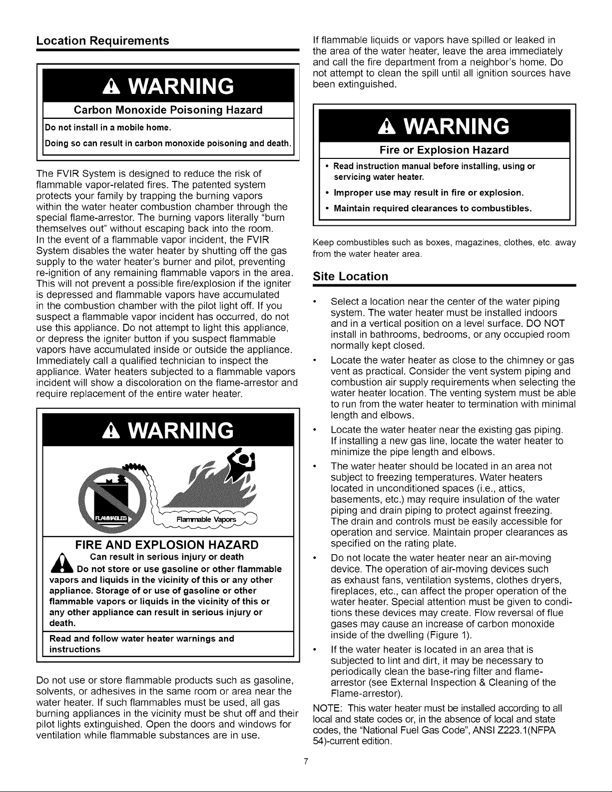
FIRE AND EXPLOSION HAZARD
,_ Can result in serious injury or death
Do not store or use gasoline or other flammable
vapors and liquids in the vicinity of this or any other
appliance. Storage of or use of gasoline or other
flammable vapors or liquids in the vicinity of this or
any other appliance can result in serious injury or
death.
Read and follow water heater warnings and
instructions
Do not use or store flammable products such as gasoline,
solvents, or adhesives in the same room or area near the
water heater. If such flammables must be used, all gas
burning appliances in the vicinity must be shut off and their
pilot lights extinguished. Open the doors and windows for
ventilation while flammable substances are in use.
If flammable liquids or vapors have spilled or leaked in
the area of the water heater, leave the area immediately
and call the fire department from a neighbor's home. Do
not attempt to clean the spill until all ignition sources have
been extinguished.
Fire or Explosion Hazard
• Readinstructionmanualbeforeinstalling,usingor
servicingwaterheater.
• Improper use may result in fire or explosion.
• Maintain required clearances to combustibles.
Keep combustibles such as boxes, magazines, clothes, etc. away
from the water heater area.
Site Location
• Select a location near the center of the water piping
system. The water heater must be installed indoors
and in a vertical position on a level surface. DO NOT
install in bathrooms, bedrooms, or any occupied room
normally kept closed.
• Locate the water heater as close to the chimney or gas
vent as practical. Consider the vent system piping and
combustion air supply requirements when selecting the
water heater location. The venting system must be able
to run from the water heater to termination with minimal
length and elbows.
• Locate the water heater near the existing gas piping.
If installing a new gas line, locate the water heater to
minimize the pipe length and elbows.
• The water heater should be located in an area not
subject to freezing temperatures. Water heaters
located in unconditioned spaces (i.e., attics,
basements, etc.) may require insulation of the water
piping and drain piping to protect against freezing.
The drain and controls must be easily accessible for
operation and service. Maintain proper clearances as
specified on the rating plate.
• Do not locate the water heater near an air-moving
device. The operation of air-moving devices such
as exhaust fans, ventilation systems, clothes dryers,
fireplaces, etc., can affect the proper operation of the
water heater. Special attention must be given to condi-
tions these devices may create. Flow reversal of flue
gases may cause an increase of carbon monoxide
inside of the dwelling (Figure 1).
• If the water heater is located in an area that is
subjected to lint and dirt, it may be necessary to
periodically clean the base-ring filter and flame-
arrestor (see External Inspection & Cleaning of the
Flame-arrestor).
NOTE: This water heater must be installed according to all
local and state codes or, in the absence of local and state
codes, the "National Fuel Gas Code", ANSI Z223. I(NFPA
54)-current edition.
Pmpe_y Damage Hazard
• AJlwater heaterseventually leak
EXHAUST FAN
• Do notinstall without adequate drainage,
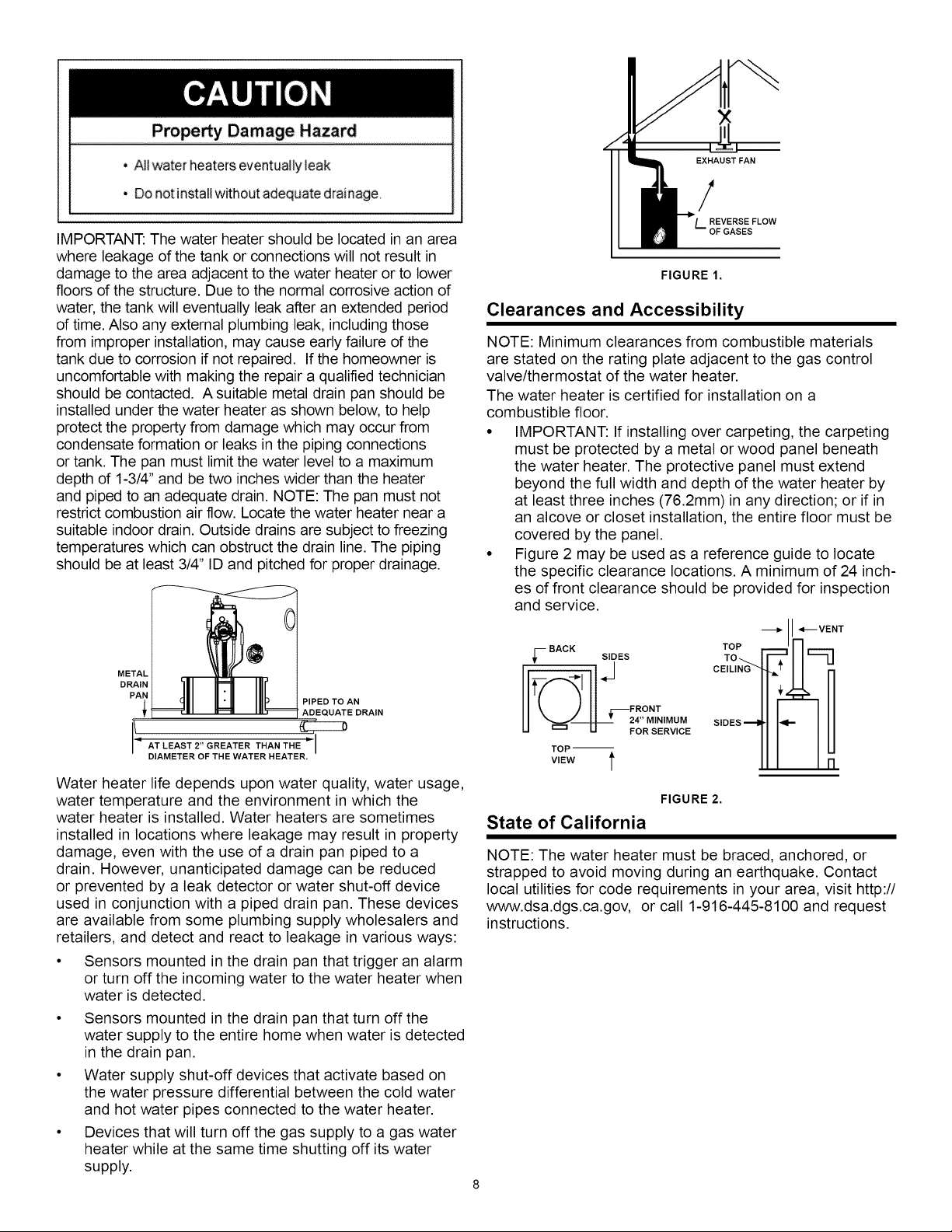
IMPORTANT: The water heater should be located in an area
where leakage of the tank or connections will not result in
damage to the area adjacent to the water heater or to lower
floors of the structure. Due to the normal corrosive action of
water, the tank will eventually leak after an extended period
of time. Also any external plumbing leak, including those
from improper installation, may cause early failure of the
tank due to corrosion if not repaired. If the homeowner is
uncomfortable with making the repair a qualified technician
should be contacted. A suitable metal drain pan should be
installed under the water heater as shown below, to help
protect the property from damage which may occur from
condensate formation or leaks in the piping connections
or tank. The pan must limit the water level to a maximum
depth of 1-3/4" and be two inches wider than the heater
and piped to an adequate drain. NOTE: The pan must not
restrict combustion air flow. Locate the water heater near a
suitable indoor drain. Outside drains are subject to freezing
temperatures which can obstruct the drain line. The piping
should be at least 3/4" ID and pitched for proper drainage.
/
REVERSE FLOW
L. OF GASES
FIGURE 1.
Clearances and Accessibility
NOTE: Minimum clearances from combustible materials
are stated on the rating plate adjacent to the gas control
valve/thermostat of the water heater.
The water heater is certified for installation on a
combustible floor.
• IMPORTANT: If installing over carpeting, the carpeting
must be protected by a metal or wood panel beneath
the water heater. The protective panel must extend
beyond the full width and depth of the water heater by
at least three inches (76.2mm) in any direction; or if in
an alcove or closet installation, the entire floor must be
covered by the panel.
• Figure 2 may be used as a reference guide to locate
the specific clearance locations. A minimum of 24 inch-
es of front clearance should be provided for inspection
and service.
_VENT
TOP
METAL
DRAIN
PAN
PIPED TO AN
ADEQUATE DRAIN
\ ATLEAST2"GREATERTHAHTH '
DIAMETER OF THE WATER HEATER.
Water heater life depends upon water quality, water usage,
water temperature and the environment in which the
water heater is installed. Water heaters are sometimes
installed in locations where leakage may result in property
damage, even with the use of a drain pan piped to a
drain. However, unanticipated damage can be reduced
or prevented by a leak detector or water shut-off device
used in conjunction with a piped drain pan. These devices
are available from some plumbing supply wholesalers and
retailers, and detect and react to leakage in various ways:
• Sensors mounted in the drain pan that trigger an alarm
or turn off the incoming water to the water heater when
water is detected.
• Sensors mounted in the drain pan that turn off the
water supply to the entire home when water is detected
in the drain pan.
• Water supply shut-off devices that activate based on
the water pressure differential between the cold water
and hot water pipes connected to the water heater.
• Devices that will turn off the gas supply to a gas water
heater while at the same time shutting off its water
supply.
;--BACKS,OES
U _ U FOR SERVICE
TOP --
VIEW t
T CE,L,
I!
IMUM SIDESll f
FIGURE 2.
State of California
NOTE: The water heater must be braced, anchored, or
strapped to avoid moving during an earthquake. Contact
local utilities for code requirements in your area, visit http://
www.dsa.dgs.ca.gov, or call 1-916-445-8100 and request
instructions.

MANUAL GAS _
SHUT-OFF VALVE--_
Explosion Hazard
• Usea newCSAapprovedgassupplyline.
• Installa shut-offvalve.
• Donot connecta naturalgaswaterheatertoan L.P.gas
supply.
• Donot connectanL.P.gaswater heatertoa naturalgas
supply.
• Failureto follow theseinstructionscanresultin death,
explosion,orcarbonmonoxidepoisoning.
Gas Requirements
IMPORTANT: Read the rating plate to be sure the water
heater is made for the type of gas you will be using in
your home. This information will be found on the rating
plate located near the gas control valve/thermostat. If the
information does not agree with the type of gas available,
do not install or light. Call your dealer.
NOTE: An odorant is added by the gas supplier to the gas
used by this water heater. This odorant may fade over an
extended period of time. Do not depend upon this odorant
as an indication of leaking gas.
Gas Piping
The gas piping must be installed according to all local and
state codes or, in the absence of local and state codes, the
"National Fuel Gas Code", ANSI Z223.1(NFPA 54)-current
edition.
Tables 1 and 2 on the following page provide a sizing
reference for commonly used gas pipe materials. Consult
the "National Fuel Gas Code" for the recommended gas
pipe size of other materials.
NOTE: Use pipe joint compound or teflon tape marked as
being resistant to the action of petroleum [Propane (L.R)]
gases (See Figure 3.)
1. Install a readily accessible manual shut-off valve in the
gas supply line as recommended by the local utility.
Know the location of this valve and how to turn off the
gas to this unit.
2. Install a drip leg (if not already incorporated as part of
the water heater) as shown. The drip leg must be no
less than three inches long for the accumulation of dirt,
foreign material, and water droplets.
3. Install a ground joint union between the gas control
valve/thermostat and the manual shut-off valve. This
is to allow easy removal of the gas control valve/
thermostat.
4. Turn the gas supply on and check for leaks. Test all
connections by brushing on an approved noncorrosive
leak-detection solution. Bubbles will show a leak.
Correct any leak found.
GROUND-------=
JOINT
UNION
CHECK WITH
LOCAL UTILITY
FOR MINIMUM HEIGHT
3" MINIMUM
DRIP LEG_
t/
SUITABLE DRAIN "--_'_ f
FIGURE 3.
DISCHARGE PiPE
(DO NOT PLUG OR CAP)
_6" MAXIMUM
_ T AIR GAP
Gas Pressure
Explosion Hazard
• Gas leaks can not always be detected by smell.
• Gas suppliers recommend that you usea gas
detector approved by UL or CSA.
• For more information, contact your gas supplier.
• If a gas leak is detected, follow the "What to do ifyou
smell gas" instructions on the cover of this manual.
IMPORTANT: The gas supply pressure must not exceed the
maximum supply pressure as stated on the water heater's rating
plate. The minimum supply pressure is for the purpose of input
adjustment.
Gas Pressure Testing
IMPORTANT: This water heater and its gas connection must
be leak tested before placing the appliance inoperation.
• If the code requires the gas lines to be tested at a
pressure exceeding 14"W.C., the water heater and its
manual shut-off valve must be disconnected from the gas
supply piping system and the line capped.
• If the gas lines are to be tested at a pressure less than
14"W.C., the water heater must be isolated from the gas
supply piping system by closing its manual shut-off valve.
NOTE: Air may be present in the gas lines and could prevent
the pilot from lighting on initial start-up. The gas lines should
be purged of air by a qualified technician after installation of
the gas piping system. While purging the gas piping system
of air, insure that the fuel is not spilled in the area of the
water heater installation, or any source of ignition. If the
fuel is spilled while purging the piping system of air follow
the "WHAT TO DO IF YOU SMELL GAS" instructions on
the cover of this manual.
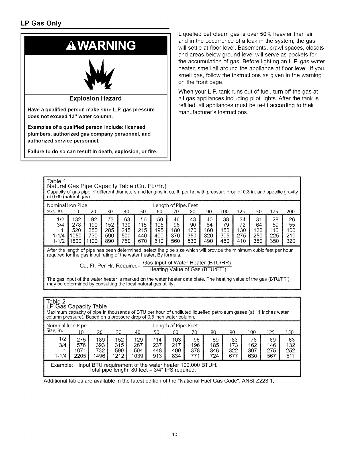
LP Gas Only
Explosion Hazard
Have a qualified person make sure L.P. gas pressure
does not exceed 13" water column.
Examples of a qualified person include: licensed
plumbers, authorized gas company personnel, and
authorized service personnel.
Failure to do so can result in death, explosion, or fire.
Table 1
Natural Gas Pipe Capacity Table (Cu. Ft./Hr.)
Capacity of gas pipe of different diameters and lengths in cu. ft. per hr. with pressure drop of 0.3 in. and specific gravity
of 0.60 (natural gas).
Nominal Iron Pipe Length of Pipe, Feet
Size, in. 10 20 30 40 50 60 70 80 90 100 125 150 175 200
112 132 92 73 63 56 50 46 43 40 38 34 3! 28 26
3/4 278 190 152 130 115 105 96 90 84 79 72 64 59 55
1 520 350 285 245 215 195 180 170 160 150 130 120 110 100
1-1/4 1050 730 590 500 440 400 370 350 320 305 275 250 225 210
1-1/2 1600 1100 890 760 670 610 560 530 490 460 410 380 350 320
After the length of pipe has been determined, select the pipe size which will provide the minimum cubic feet per hour
required for the gas input rating of the water heater. Byformula:
Cu. Ft. Per Hr. Required=
The gas input of the water heater is marked on the water heater data plate. The heating value of the gas (BTU/FT 3)
may be determined by consulting the local natural gas utility.
Liquefied petroleum gas is over 50% heavier than air
and in the occurrence of a leak in the system, the gas
will settle at floor level. Basements, crawl spaces, closets
and areas below ground level will serve as pockets for
the accumulation of gas. Before lighting an L.R gas water
heater, smell all around the appliance at floor level. If you
smell gas, follow the instructions as given in the warning
on the front page.
When your L.P. tank runs out of fuel, turn off the gas at
all gas appliances including pilot lights. After the tank is
refilled, all appliances must be re-lit according to their
manufacturer's instructions.
Gas Input of Water Heater (BTU/HR)
Heating Value of Gas (BTU/FT 3)
Table 2
LP Gas Capacity Table
Maximum capacity of pipe in thousands of BTU per hour of undiluted liquefied petroleum gases (at 11 inches water
column pressure). Based on a pressure drop of 0.5 inch water column.
Nominallron Pipe Length ofPipe, Feet
Size, in. 1__0_____Z0_______5_0_ 7__
1/2 275 189 152 129 114 103 96
3/4 576 393 315 267 237 217 196
1 1071 732 590 504 448 409 378
1-1_ 2205 1496 1212 1039 913 834 771
Example: Input BTU requirement of the water heater 100,000 BTUH.
Total pipe length, 80 feet = 3/4" IPS required.
Additional tables are available in the latest edition of the "National Fuel Gas Code", ANSI Z223.1.
10
.__SD____9_0___l__L0_0___.J25_1__15_D_
89 83 78 69 63
185 173 162 146 132
346 322 307 275 252
724 677 630 567 511
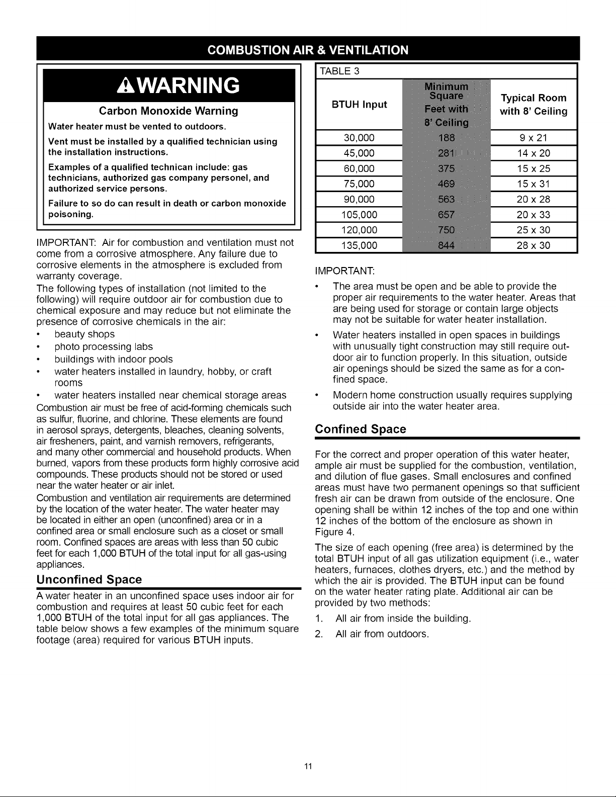
TABLE 3
Carbon Monoxide Warning
Water heater must be vented to outdoors.
Vent must be installed by a qualified technician using
the installation instructions.
Examples of a qualified technican include: gas
technicians, authorized gas company personel, and
authorized service persons.
Failure to so do can result in death or carbon monoxide
poisoning.
IMPORTANT: Air for combustion and ventilation must not
come from a corrosive atmosphere. Any failure due to
corrosive elements in the atmosphere is excluded from
warranty coverage.
The following types of installation (not limited to the
following) will require outdoor air for combustion due to
chemical exposure and may reduce but not eliminate the
presence of corrosive chemicals in the air:
• beauty shops
• photo processing labs
• buildings with indoor pools
• water heaters installed in laundry, hobby, or craft
rooms
• water heaters installed near chemical storage areas
Combustion air must be free of acid-forming chemicals such
as sulfur, fluorine, and chlorine. These elements are found
in aerosol sprays, detergents, bleaches, cleaning solvents,
air fresheners, paint, and varnish removers, refrigerants,
and many other commercial and household products. When
burned, vapors from these products form highly corrosive acid
compounds. These products should not be stored or used
near the water heater or air inlet.
Combustion and ventilation air requirements are determined
by the location of the water heater. The water heater may
be located in either an open (unconfined) area or in a
confined area or small enclosure such as a closet or small
room. Confined spaces are areas with less than 50 cubic
feet for each 1,000 BTUH of the total input for all gas-using
appliances.
Unconfined Space
A water heater in an unconfined space uses indoor air for
combustion and requires at least 50 cubic feet for each
1,000 BTUH of the total input for all gas appliances. The
table below shows a few examples of the minimum square
footage (area) required for various BTUH inputs.
BTUH Input
30,000
45,000
60,000
75,000
90,000
105,000
120,000
135,000
Typical Room
with 8' Ceiling
9x21
14 x20
15x25
15x31
20 x 28
20 x 33
25 x 30
28 x 30
IMPORTANT:
• The area must be open and be able to provide the
proper air requirements to the water heater. Areas that
are being used for storage or contain large objects
may not be suitable for water heater installation.
• Water heaters installed in open spaces in buildings
with unusually tight construction may still require out-
door air to function properly. In this situation, outside
air openings should be sized the same as for a con-
fined space.
• Modern home construction usually requires supplying
outside air into the water heater area.
Confined Space
For the correct and proper operation of this water heater,
ample air must be supplied for the combustion, ventilation,
and dilution of flue gases. Small enclosures and confined
areas must have two permanent openings so that sufficient
fresh air can be drawn from outside of the enclosure. One
opening shall be within 12 inches of the top and one within
12 inches of the bottom of the enclosure as shown in
Figure 4.
The size of each opening (free area) is determined by the
total BTUH input of all gas utilization equipment (i.e., water
heaters, furnaces, clothes dryers, etc.) and the method by
which the air is provided. The BTUH input can be found
on the water heater rating plate. Additional air can be
provided by two methods:
1. All air from inside the building.
2. All air from outdoors.
11
 Loading...