

A.O. Smith BTH-120A, BTH-150A, BTH-199A, BTH-250A, BTH-300A Installation Manual
...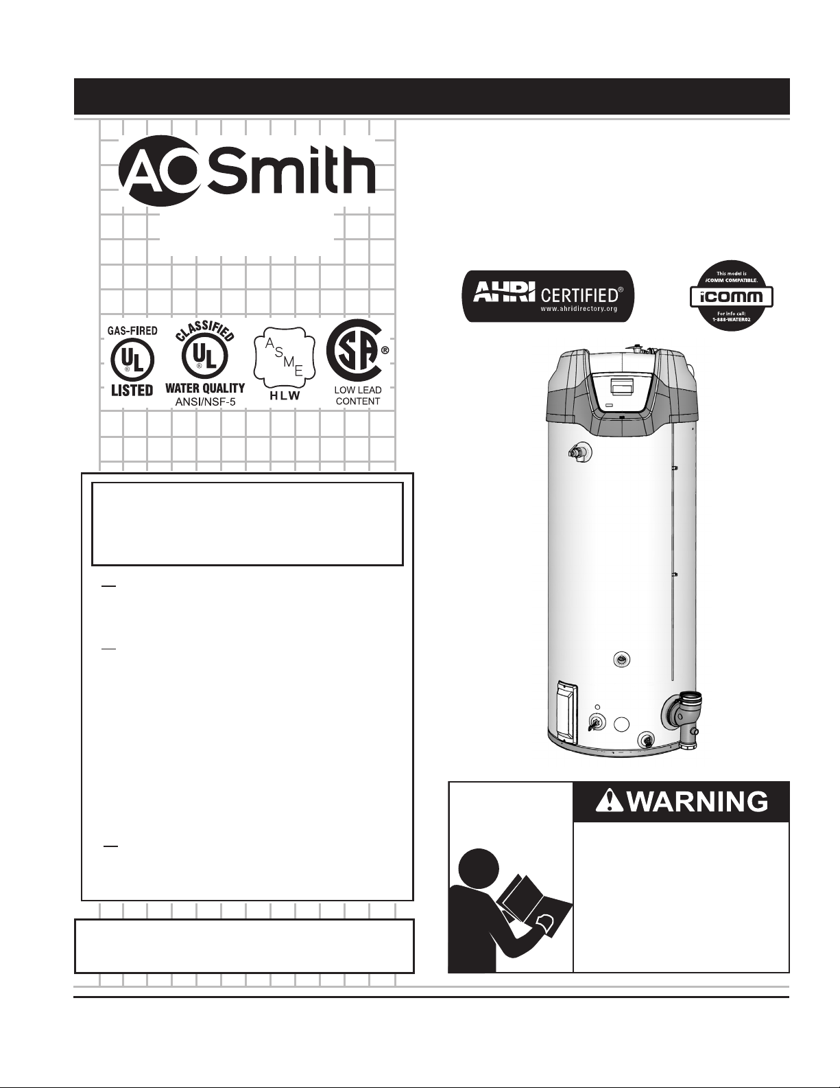
Instruction Manual
COMMERCIAL GAS WATER HEATERS
MODELS
BTH-120(A)/150(A)/199(A)/250(A)
SERIES 200 & 201
500 Tennessee Waltz Parkway
Ashland City, TN 37015
www.hotwater.com
INSTALLATION - OPERATION - SERVICE
- MAINTENANCE - LIMITED WARRANTY
WARNING: If the information in these
instructions is not followed exactly, a fire
or explosion may result causing property
damage, personal injury or death.
Do not store or use gasoline or other
flammable vapors and liquids in the
vicinity of this or any other appliance.
WHAT TO DO IF YOU SMELL GAS:
Do not try to light any appliance.
•
Do not touch any electrical switch; do
•
not use any phone in your building.
Immediately call your gas supplier
•
from a neighbor’s phone. Follow the
gas supplier’s instructions.
If you cannot reach your gas supplier,
•
call the fire department.
Installation and service must be
performed by a qualified installer,
service agency or the gas supplier.
Thank you for buying this energy efcient water heater.
We appreciate your condence in our products.
Read and understand this instruction
manual and the safety messages
herein before installing, operating or
servicing this water heater.
Failure to follow these instructions and
safety messages could result in death
or serious injury.
This manual must remain with the
water heater.
PLACE THESE INSTRUCTIONS ADJACENT TO HEATER AND NOTIFY OWNER TO KEEP FOR FUTURE REFERENCE.
PRINTED 0514 327727-000

TABLE OF CONTENTS
SAFE INSTALLATION, USE AND SERVICE.......................................... 3
APPROVALS .......................................................................................... 3
GENERAL SAFETY INFORMATION ...................................................... 4
Precautions ........................................................................................ 4
Grounding Instructions ...................................................................... 4
Hydrogen Gas Flammable ................................................................. 4
INTRODUCTION .................................................................................... 6
Abbreviations Used ........................................................................... 6
Qualications ..................................................................................... 6
iCOMM™ & BACnet Compatible ....................................................... 6
Preparing For The Installation ...........................................................6
FEATURES AND COMPONENTS ......................................................... 7
Basic Operation ................................................................................. 7
Modulation ......................................................................................... 7
Blower/Burner Assembly Detail ......................................................... 7
Top View ............................................................................................ 8
Side Views ......................................................................................... 9
INSTALLATION CONSIDERATIONS ................................................... 10
Rough In Dimensions ......................................................................10
Locating The Water Heater ...............................................................11
Extended Vent Terminations ............................................................ 12
Optional Concentric & Low Prole Terminations.............................. 12
Hard Water ......................................................................................12
Circulation Pumps ........................................................................... 12
Insulation Blankets .......................................................................... 12
INSTALLATION REQUIREMENTS ...................................................... 13
Gas Supply Systems .......................................................................13
Supply Gas Regulator ..................................................................... 13
Power Supply .................................................................................. 13
Mixing Valves ................................................................................... 14
Dishwashing Machines .................................................................... 14
Closed Water Systems .................................................................... 14
Thermal Expansion .......................................................................... 14
Temperature-Pressure Relief Valve ................................................. 15
Condensate Drain ............................................................................ 16
Combustible Material Storage .........................................................16
Contaminated Air ............................................................................. 16
Air Requirements ............................................................................. 17
Unconned Space ...........................................................................17
Conned Space ............................................................................... 17
Fresh Air Openings For Conned Spaces ....................................... 18
Outdoor Air Through Two Openings ................................................ 18
Outdoor Air Through One Opening .................................................. 18
Outdoor Air Through Two Horizontal Ducts ..................................... 18
Outdoor Air Through Two Vertical Ducts .......................................... 19
Air From Other Indoor Spaces ......................................................... 19
INSTALLATION REQUIREMENTS - COMMONWEALTH OF
MASSACHUSETTS .............................................................................. 20
VENTING INSTALLATION ................................................................... 21
General Venting Information ............................................................ 21
General Venting Instructions ...........................................................21
Intake Air Connection ......................................................................22
Venting Requirements ..................................................................... 22
Venting Installation Sequence ......................................................... 23
Power Vent Installation .................................................................... 23
Direct Vent Installation ..................................................................... 24
Vertical Termination Installation ....................................................... 25
Sidewall Termination Installation...................................................... 27
Polypropylene Installations .............................................................. 28
AL29-4C® Vent Installations ........................................................... 29
Concentric Termination Installation .................................................. 30
4 Inch Concentric Termination Installation ....................................... 31
Low Prole Vent installation ............................................................. 34
Venting Arrangements ..................................................................... 35
Termination Clearances Sidewall Power Vent ................................. 37
Termination Clearances Sidewall Direct Vent .................................. 38
WATER HEATER INSTALLATION ........................................................ 39
Condensate Drain Installation ......................................................... 39
Supply Gas Line Installation ............................................................ 40
Gas Line Leak Testing ..................................................................... 41
Purging ............................................................................................41
Electrical Wiring ............................................................................... 41
Enable / Disable Circuit (For Building Management Systems) ........ 42
Water Line Connections ..................................................................43
T&P Valve Discharge Pipe ............................................................... 43
TEMPERATURE REGULATION .......................................................... 44
High Temperature Limit Control (ECO) ............................................ 44
Thermostat Control .......................................................................... 44
CONTROL SYSTEM OPERATION ...................................................... 45
Overview .......................................................................................... 45
Control System Navigation .............................................................. 45
User Settings & Control System Menus .......................................... 48
START UP ............................................................................................ 53
Prior to Start up ............................................................................... 53
Initial Start Up .................................................................................. 53
Lighting & Operation Labels ............................................................54
Checking The Firing Rate ................................................................ 56
High Altitude Installations ................................................................56
TROUBLESHOOTING ......................................................................... 57
Installation Checklist ........................................................................ 57
Sequence Of Operation ................................................................... 57
Sequence Of Operation Flow Chart ................................................ 58
Operational Problems ...................................................................... 59
Fault And Alert Conditions ............................................................... 60
MAINTENANCE ................................................................................... 63
General ............................................................................................ 63
Maintenance Schedule .................................................................... 63
Draining And Flushing .....................................................................63
Filling The Water Heater .................................................................. 64
Sediment Removal ..........................................................................64
Lime Scale Removal ........................................................................ 64
Powered Anode Rods ...................................................................... 65
Drain Valve and Access Panels ....................................................... 65
Vent System ....................................................................................65
DIAGRAMS .......................................................................................... 66
CCB - Central Control Board Layout ...............................................66
Wiring Diagram ................................................................................ 67
Circulation Pump Wiring Diagrams .................................................. 68
Water Piping Diagrams .................................................................... 69
NOTES ................................................................................................. 76
NOTES ................................................................................................. 77
NOTES ................................................................................................. 78
SERVICE INQUIRIES: ......................................................................... 79
COMMERCIAL ..................................................................................... 79
WATER HEATER ................................................................................. 79
LIMITED WARRANTY .......................................................................... 79
2
SAFE INSTALLATION, USE AND SERVICE
The proper installation, use and servicing of this water heater is extremely important to your safety and the safety of others.
Many safety-related messages and instructions have been provided in this manual and on your own water heater to warn you and
others of a potential injury hazard. Read and obey all safety messages and instructions throughout this manual. It is very important
that the meaning of each safety message is understood by you and others who install, use, or service this water heater.
This is the safety alert symbol. It is used to alert you to
potential personal injury hazards. Obey all safety
messages that follow this symbol to avoid possible
injury or death.
DANGER indicates an imminently
DANGER
WARNING
CAUTION
hazardous situation which, if not avoided,
will result in injury or death.
WARNING indicates a potentially hazardous
situation which, if not avoided, could result
in injury or death.
CAUTION indicates a potentially hazardous
situation which, if not avoided, could result in
minor or moderate injury.
CAUTION used without the safety alert
CAUTION
All safety messages will generally tell you about the type of hazard, what can happen if you do not follow the safety message, and
how to avoid the risk of injury.
The California Safe Drinking Water and Toxic Enforcement Act requires the Governor of California to publish a list of substances
known to the State of California to cause cancer, birth defects, or other reproductive harm, and requires businesses to warn of
potential exposure to such substances.
This product contains a chemical known to the State of California to cause cancer, birth defects, or other reproductive harm. This
water heater can cause low level exposure to some of the substances listed in the Act.
symbol indicates a potentially hazardous
situation which, if not avoided, could result in
property damage.
APPROVALS
NOTE: ASME construction is optional on the water
heaters covered in this manual.
3
GENERAL SAFETY INFORMATION
PRECAUTIONS
DO NOT USE THIS WATER HEATER IF ANY PART HAS
BEEN EXPOSED TO FLOODING OR WATER DAMAGE.
Immediately call a qualied service agency to inspect the
water heater and to make a determination on what steps
should be taken next.
If the unit is exposed to the following, do not operate heater
until all corrective steps have been made by a qualified
service agency.
1. External re.
2. Damage.
3. Firing without water.
GROUNDING INSTRUCTIONS
This water heater must be grounded in accordance with the
National Electrical Code and/or local codes. These must be
followed in all cases. Failure to ground this water heater
properly may also cause erratic control system operation.
This water heater must be connected to a grounded metal,
permanent wiring system; or an equipment grounding
conductor must be run with the circuit conductors and
connected to the equipment grounding terminal or lead on
the water heater.
Verify the power to the water heater is turned off before performing any service procedures.
The Enable /Disable switch on front panel disables the 24 volt gas valve. Electrical supply
must be turned off at circuit breaker serving water heater.
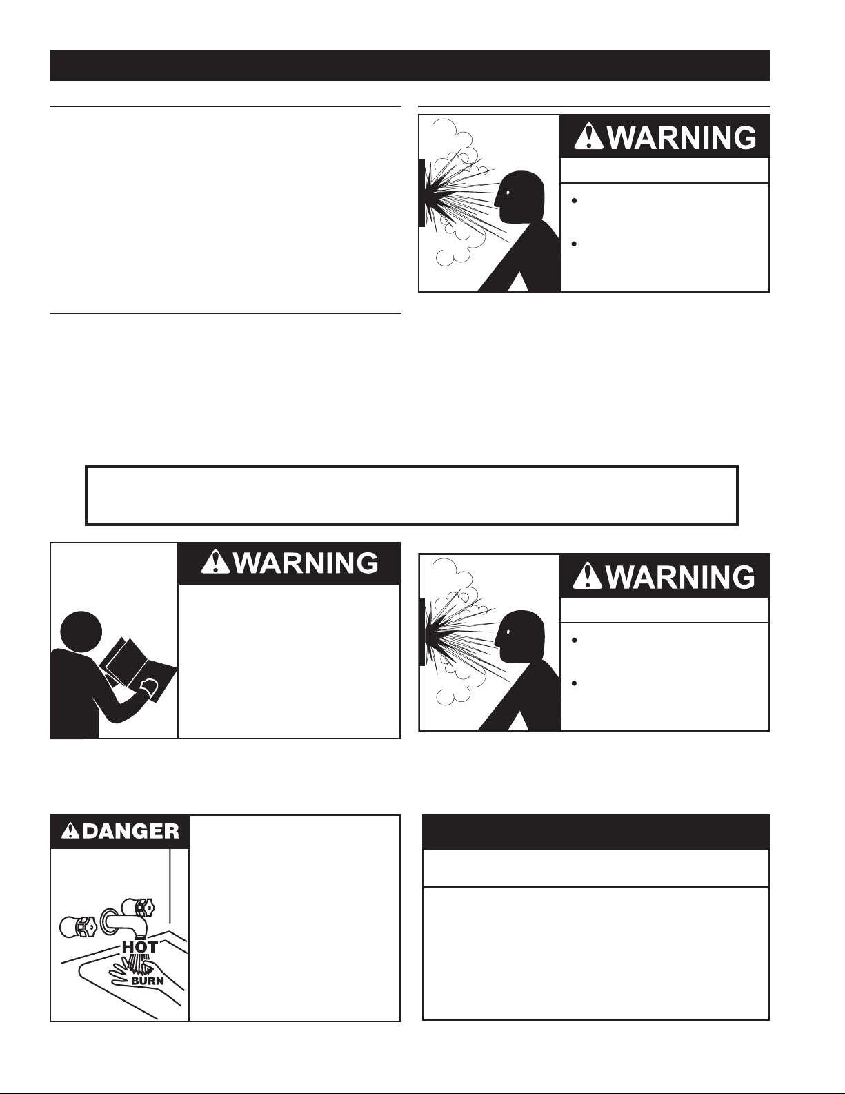
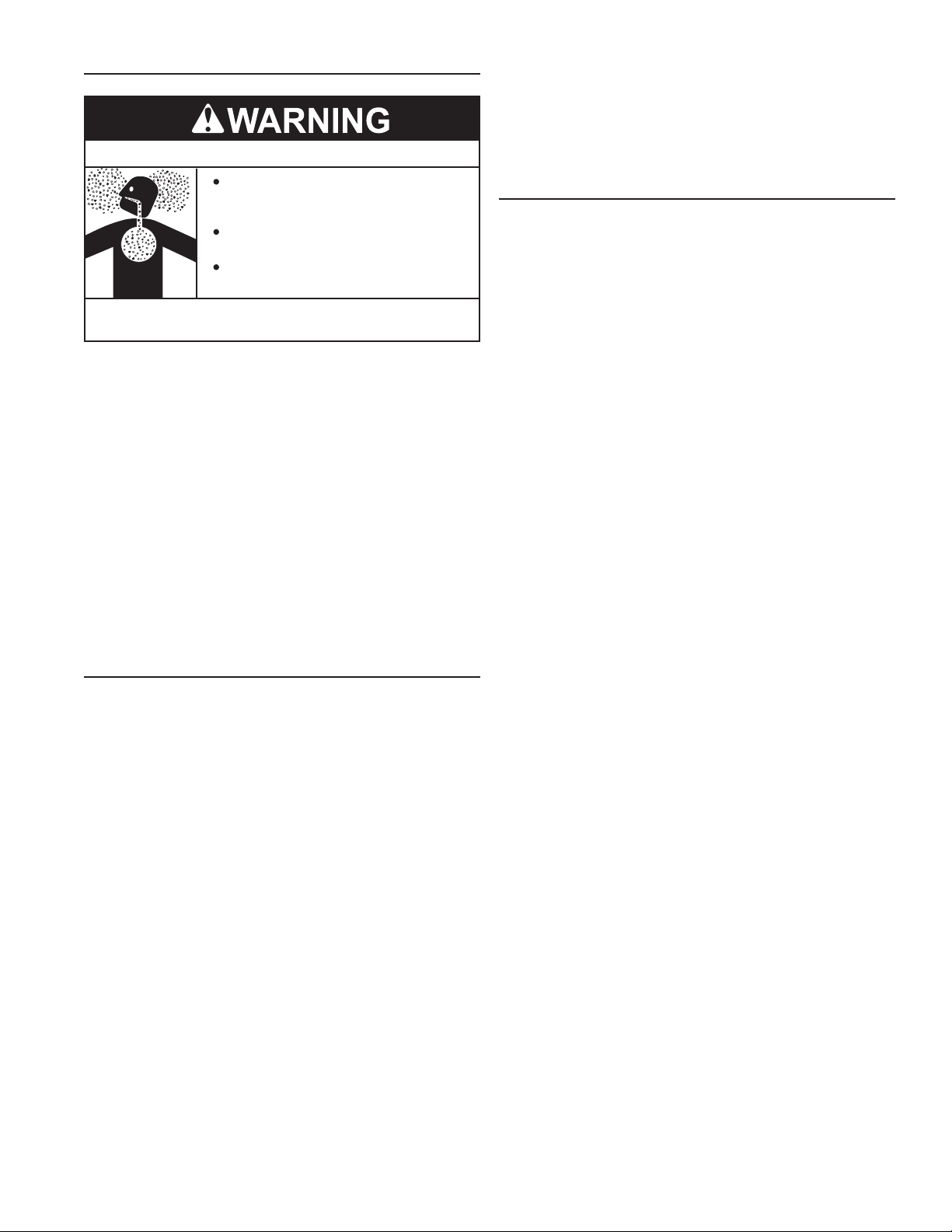
HYDROGEN GAS FLAMMABLE
Explosion Hazard
Flammable hydrogen gases
may be present.
Keep all ignition sources away
from faucet when turning on
hot water.
Hydrogen gas can be produced in a hot water system served
by this water heater that has not been used for a long period of
time (generally two weeks or more). Hydrogen gas is extremely
ammable. To reduce the risk of injury under these conditions, it is
recommended that a hot water faucet served by this water heater
be opened for several minutes before using any electrical appliance
connected to the hot water system. If hydrogen is present there will
probably be an unusual sound such as air escaping through the pipe
as the water begins to ow. THERE SHOULD BE NO SMOKING
OR OPEN FLAME NEAR THE FAUCET AT THE TIME IT IS OPEN.
Read and understand this instruction
manual and the safety messages
herein before installing, operating or
servicing this water heater.
Failure to follow these instructions and
safety messages could result in death
or serious injury.
This manual must remain with the
water heater.
Water temperature over 125°F (52°C)
can cause severe burns instantly
resulting in severe injury or death.
Children, the elderly and the
physically or mentally disabled are at
highest risk for scald injury.
Feel water before bathing or
showering.
Temperature limiting devices such as
mixing valves must be installed
when required by codes and to
ensure safe temperatures at fixtures.
Explosion Hazard
Overheated water can cause
water tank explosion.
Properly sized temperature and
pressure relief valve must be
installed in the opening provided.
CAUTION
Improper installation, use and service may result
in property damage.
Do not operate water heater if exposed to flooding or
•
water damage.
Inspect anode rods regularly, replace if damaged.
•
Install in location with drainage.
•
Fill tank with water before operation.
•
Properly sized thermal expansion tanks are required on all
•
closed water systems.
Refer to this manual for installation and service.
4
GENERAL SAFETY INFORMATION
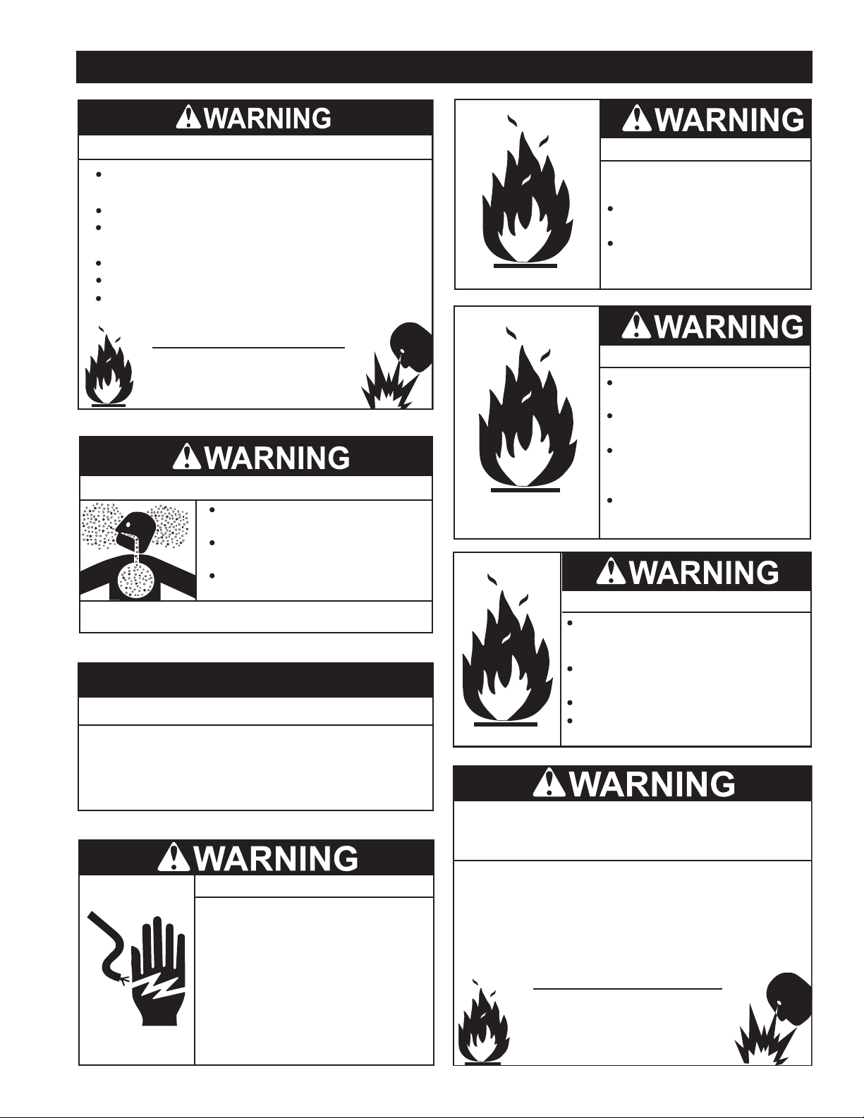
Fire or Explosion Hazard
Do not store or use gasoline or other flammable vapors and
liquids in the vicinity of this or any other appliance.
Avoid all ignition sources if you smell gas.
Do not expose water heater controls to excessive gas
pressure.
Use only the gas shown on the water heater rating label.
Maintain required clearances to combustibles.
Keep ignition sources away from faucets after extended
periods of non-use.
Read instruction manual before
installing, using or servicing
water heater.
Breathing Hazard - Carbon Monoxide Gas
Do not obstruct water heater air intake
with insulating blanket.
Gas and carbon monoxide detectors
are available.
Install water heater in accordance with
the instruction manual.
Breathing carbon monoxide can cause brain damage or
death. Always read and understand instruction manual.
CAUTION
Property Damage Hazard
All water heaters eventually leak.
•
Fire Hazard
For continued protection against
risk of fire:
Do not install water heater on
carpeted floor.
Do not operate water heater if
exposed to flooding or water
damage.
Fire and Explosion Hazard
Use joint compound or Teflon tape
compatible with propane gas.
Leak test gas connections before
placing water heater in operation.
Disconnect gas piping at main
gas shutoff valve before leak
testing heater.
Install sediment trap in
accordance with NFPA 54 or
CAN/CSA B149.1.
Fire and Explosion Hazard
Do not use water heater with any gas
other than the gas shown on the rating
label.
Excessive gas pressure to gas valve can
cause serious injury or death.
Turn off gas lines during installation.
Contact a qualified installer or service
agency for installation and service.
Do not install without adequate drainage.
•
Electrical Shock Hazard
Turn off power at the branch circuit
•
breaker serving the water heater
before performing any service.
Label all wires prior to disconnecting
•
when performing service. Wiring errors
can cause improper and dangerous
operation.
Verify proper operation after servicing.
•
Failure to follow these instructions can
•
result in personal injury or death.
Jumping out control circuits or components can
result in property damage, personal injury or death.
Service should only be performed by a qualified service
•
technician using proper test equipment.
Altering the water heater controls and/or wiring in any way
•
could result in permanent damage to the controls or water
heater and is not covered under the limited warranty.
Any bypass or alteration of the water
heater controls and/or wiring will result
in voiding the appliance warranty.
5

INTRODUCTION
Thank You for purchasing this water heater. Properly installed
and maintained, it should give you years of trouble free service.
ABBREVIATIONS USED
Abbreviations found in this Instruction Manual include :
• ANSI - American National Standards Institute
• ASME - American Society of Mechanical Engineers
• AHRI - Air Conditioning, Heating and Refrigeration Institute
• NEC - National Electrical Code
• NFPA - National Fire Protection Association
• UL - Underwriters Laboratory
• CSA - Canadian Standards Association
QUALIFICATIONS
QUALIFIED INSTALLER OR SERVICE AGENCY
Installation and service of this water heater requires ability
equivalent to that of a Qualied Agency (as dened by ANSI
below) in the eld involved. Installation skills such as plumbing,
air supply, venting, gas supply and electrical supply are required
in addition to electrical testing skills when performing service.
ANSI Z223.1 2006 Sec. 3.3.83: “Qualied Agency” - “Any
individual, rm, corporation or company that either in person or
through a representative is engaged in and is responsible for (a)
the installation, testing or replacement of gas piping or (b) the
connection, installation, testing, repair or servicing of appliances
and equipment; that is experienced in such work; that is familiar
with all precautions required; and that has complied with all the
requirements of the authority having jurisdiction.”
If you are not qualied (as dened by ANSI above) and licensed
or certied as required by the authority having jurisdiction
to perform a given task do not attempt to perform any of the
procedures described in this manual. If you do not understand
the instructions given in this manual do not attempt to perform
any procedures outlined in this manual.
ICOMM™ & BACNET COMPATIBLE
This water heater is compatible with the iCOMM™ remote
monitoring system. The iCOMM™ system hardware and
monitoring service is purchased separately. It allows users to
monitor critical operational, diagnostic and energy usage data
from a secure web site.
The iCOMM™ system can automatically notify selected
personnel via email and/or cellular phone text messages if
operational problems or user dened Alert Conditions occur.
iCOMM™ system hardware is compatible with BACnet compliant
supervisory controls and building management systems. For
more information call 888-928-3702.
PREPARING FOR THE INSTALLATION
1. Read the entire manual before attempting to install or operate
the water heater. Pay close attention to the General Safety
Information on page 4 and 5. If you don’t follow the safety
rules, the water heater may not operate safely. It could cause
property damage, injury and/or death.
This manual contains instructions for the installation,
operation, and maintenance of the water heater. It also
contains warnings throughout the manual that you must read
and be aware of. All warnings and all instructions are essential
to the proper operation of the water heater and your safety.
Detailed installation diagrams are also found in this manual.
These diagrams will serve to provide the installer with a
reference. It is essential that all venting, water piping, gas
piping and wiring be installed as shown.
Particular attention should be given to the installation
of thermometers at the locations indicated in the piping
diagrams as these are necessary for checking the operation
of the water heater.
The principal components of the water heater are identied
in Features And Components on page 7 in this manual. Use
this reference to locate and identify various components on
the water heater.
See the Installation Checklist and Troubleshooting on page
57. By using this checklist the user may be able to make minor
operational adjustments and avoid unnecessary service
calls. However, service and diagnostic procedures should
only be performed by a Qualied Service Agency.
NOTE: Costs to correct installation errors are not covered
under the limited warranty.
2. Be sure to turn off power when working on or near the
electrical system of the water heater. Never touch electrical
components with wet hands or when standing in water.
3. The installation must conform to all instructions contained in
this manual and the local code authority having jurisdiction.
These shall be carefully followed in all cases. Authorities
having jurisdiction should be consulted before installation
begins if there are any questions regarding compliance with
local, state or national codes.
In the absence of local codes, the installation must comply
with the current editions of the National Fuel Gas Code, ANSI
Z223.1/NFPA 54 and the National Electrical Code, NFPA 70 or
CAN/CSA-B149.1, the Natural Gas and Propane Installation
Code and CSA C22.1, the Canadian Electrical Code. All
documents are available from the Canadian Standards
Association, 8501 East Pleasant Valley Road, Cleveland, OH
44131. NFPA documents are also available from the National
Fire Protection Association, 1 Batterymarch Park, Quincy,
MA 02269.
4. If after reading this manual you have any questions or do
not understand any portion of the instructions, call the toll
free number on the back cover of this manual for technical
assistance. In order to expedite your request, please have the
full Model, Serial and Series number of the water heater you
are working with available for the technician. This information
is located on the water heater’s rating label.
5. Carefully plan the placement of the water heater. Examine
the location to ensure that it complies with the requirements
in Locating The Water Heater on page 11 and the Rough
In Dimensions on page 10.
6. For installation in California this water heater must be braced
or anchored to avoid falling or moving during an earthquake.
See instructions for correct installation procedures.
Instructions may be obtained from California Ofce of the
State Architect, 1102 Q Street, Suite 5100, Sacramento, CA
95811.
7. Massachusetts Code requires this water heater to be
installed in accordance with Massachusetts 248-CMR 2.00:
State Plumbing Code and 248-CMR 5. See Commonwealth
of Massachusetts on page 20.
6
FEATURES AND COMPONENTS
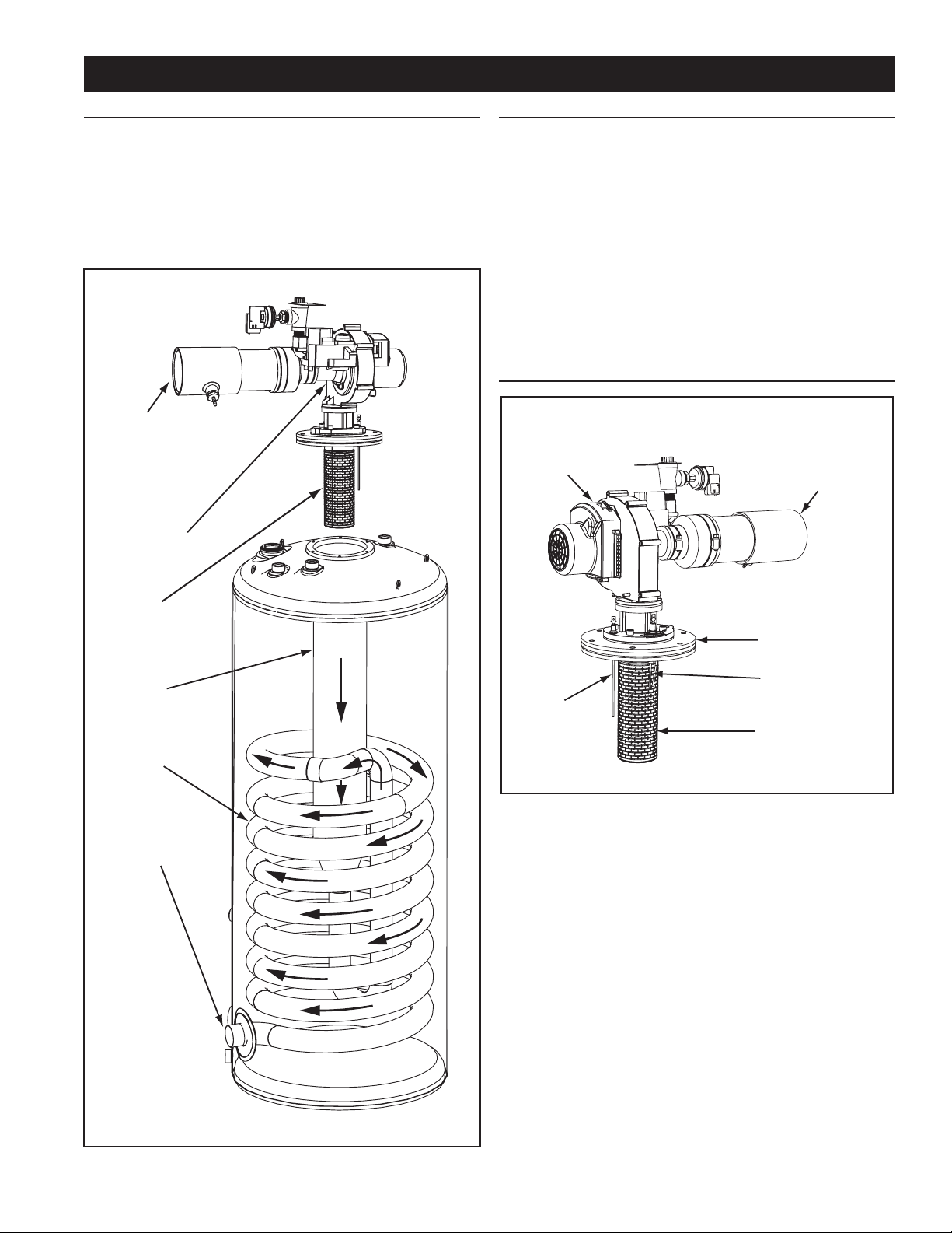
BASIC OPERATION
The water heaters covered in this manual have a helical coil
shaped heat exchanger that is submerged in the storage tank.
The water heater’s Main Burner is a radial design burner, it
is mounted on the top and res downward through the heat
exchanger. This is a forced draft burner; hot burning gases are
forced through the heat exchanger under pressure and exit
through the exhaust/vent connection located at the bottom of the
water heater. See Figure 1 and Figure 2.
INTAKE AIR
(combustion air)
CONNECTION
3 INCH PVC
BLOWER
BURNER
ASSEMBLY
MODULATION
The water heaters covered by this manual are capable of
modulating their ring rate. The CCB monitors the water
temperature in the tank and regulates the ring rate to achieve
the target temperature setpoint. The ring rate is dictated by
the hot water draw, proximity to the tank temperature setpoint,
and various other temperature limitations. Periodically, when the
heater is in modulation mode, the CCB will increase the blower
speed for a short period of time to clear out any condensation
that has accumulated in the heat exchanger then decreases
the blower speed back to the modulating ring rate required to
maintain the desired tank temperature setpoint. This ramping up
and down of the blower speed is considered normal operation of
the water heater.
BLOWER/BURNER ASSEMBLY DETAIL
COMBUSTION
BLOWER
ASSEMBLY
INTAKE AIR
(combustion air)
CONNECTION
3 INCH PVC
MAIN
BURNER
(radial design)
HEAT
EXCHANGER
HELICAL
COIL
VENT (exhaust)
OUTLET
BURNER
FLANGE
SPARK IGNITER
FLAME
SENSOR
Figure 2
Spark Igniter
The control system energizes the spark ignition control with 120
VAC during the ignition cycle. The spark ignition control then
sends a high-voltage current to the spark igniter which in turn
ignites the main burner air/gas mixture.
Flame Sensor
The control system also monitors the ame sensor to conrm
a ame is present at the Main Burner. If a ame is not veried
during the ignition trial period (3-5 seconds) the control system
will immediately de-energize the 24 Volt Gas Valve. See the
Sequence Of Operation Flow Chart on page 58.
MAIN
BURNER
(radial design)
Figure 1
7
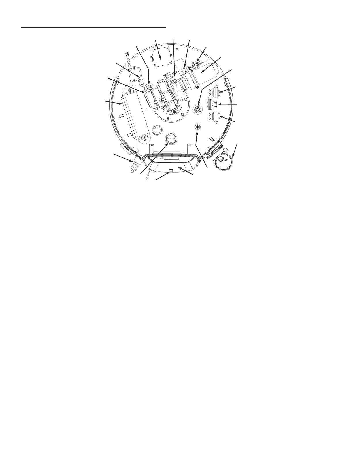
TOP VIEW OF ALL MODELS
TOP VIEW
6
5
2
18
4
8
9
11
2
13
3
14
16
1
FRONT
Figure 3
COMPONENTS (All Models)
IMPORTANT. The Enable/Disable switch listed in this manual is
NOT an "on/off" switch and does not disconnect 120 volt power
to the CCB and other heater components.
1. Water Heater’s Enable/Disable Switch. When in the "Disabled"
position the switch removes electrical power from the gas
valve and blower so that water heating is disabled. The
display, CCB, and other electrical components will still be
energized and the display will read "Water Heating Disabled".
2. Powered anode rods. The water heaters covered in this
manual are equipped with powered (non sacricial) anode
rods. The BTH 120 has one powered anode, all other models
will have two. Protective current is fed by the control system
to the titanium electrodes at the end of each anode rod. This
current ows through the water to the conductive surfaces
inside the storage tank which diminishes the corrosive effect
(rusting) of water when it comes in contact with steel.
3. Central Control Board (CCB) enclosure. This enclosure
houses the control system’s main circuit board, power supply
board, power transformer, and conguration key. The CCB
regulates water temperature and controls all water heater
functions, see Control System Operation on page 45.
4. Combustion Blower Assembly includes, Gas Valve and
Venturi gas feed system.
5. 120 VAC junction box. Incoming power supply, ground
connections, and other eld installed electrical connections
are made here. See Power Supply on page 13.
6. Water heater's 24 Volt Gas Valve.
7. Blocked Intake Air switch. Normally closed contacts that
open on fall in pressure. This switch is used to insure intake
(combustion) air to the water heater is not restricted. The
control system monitors this switch and will disable heating
operation if its contacts are open during a heating cycle.
8. Supply gas line connection. See the requirements for the
Gas Supply Systems on page 13.
9. Low Gas Pressure switch. Normally open contacts that close
on a rise in pressure. This switch is used to insure supply
7
12
10
15
17
gas pressure is above minimum requirements. The control
system monitors this switch and will disable heating operation
if its contacts are open during a heating cycle. See Gas
Pressure Requirements and Table 3 on page 11.
10. Vent connection (exhaust / condensate elbow) - three inch
aluminum.
11. Intake air connection - 3 inch PVC.
12. Blocked Exhaust (vent) switch. Normally closed contacts that
open on a rise in pressure. This switch is used to insure the
Exhaust (vent) piping connected to the water heater is not
restricted. The control system monitors this switch and will
disable heating operation if its contacts are open during a
heating cycle.
13. Blower Prover switch. Normally open contacts that close on a
rise in pressure. This switch is used to insure the Combustion
Blower is operating properly at blower start-up. The control
system monitors this switch and will disable heating operation
if its contacts are closed before the Combustion Blower is
energized. See Sequence Of Operation on page 57.
14. Temperature-Pressure Relief Valve. See TemperaturePressure Relief Valve on page 15.
15. Upper Temperature Probe, 1 of 2 temperature probes. The
water heater’s control system monitors this probe to detect
water temperature in the upper portion of the storage tank.
The Upper Temperature Probe also houses the ECO (energy
cut out) switch. This is a non adjustable high temperature
limit switch. The ECO switch contacts are normally closed
and will open on a temperature rise. See High Temperature
Limit Control (ECO) on page 44.
16. Water outlet connection 1 1/2” NPT.
17. UIM (user interface module). The UIM includes the display
circuit board, the control system’s LCD display and
operational buttons. Used to adjust various user settings and
view operational information. See Control System Operation
on page 45.
18. Spark Ignition Control. When energized, sends the electrical
current to the spark igniter.
8
5
4
3
4
6
2
13
14
16
2
1
5
3
7
8
9
15
1
10
15
11
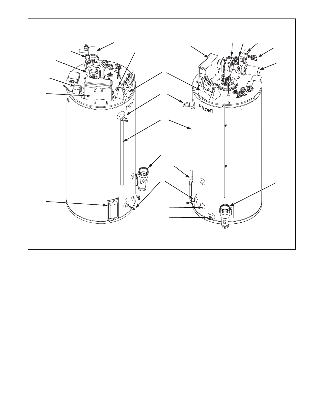
LEFT SIDE RIGHT SIDE
Figure 4
SIDE VIEWS
1. Cleanout access panel, covers water heater cleanout
opening.
2. CCB enclosure - see item 3 on page 8 for description.
3. Intake air connection - 3 inch PVC.
4. Water heater 24 Volt Gas Valve.
5. Combustion Blower.
6. Water outlet - 1 1/2” NPT connection.
7. UIM (user interface module). The UIM includes the display
circuit board, the control system’s LCD display and
operational buttons. Used to adjust various user settings and
view operational information. See Control System Operation
on page 45.
8. Temperature-Pressure Relief Valve. See TemperaturePressure Relief Valve on page 15.
12
9. Temperature-Pressure Relief Valve discharge pipe - see T&P
Valve Discharge Pipe Requirements: on page 15.
10. Lower Temperature Probe, 1 of 2 temperature probes. The
water heater’s control system monitors this probe to detect
water temperature in the lower portion of the storage tank.
11. Water inlet - 1 1/2” NPT connection.
12. Water heater drain valve.
13. Supply gas line connection. See Gas Supply Systems on
page 13.
14. Low Gas Pressure switch, see description under beginning
on page 8. See Gas Pressure Requirements and Table
3 on page 11.
15. Vent Connection (Exhaust/Condensate Elbow) 3" Aluminum.
16. Spark Ignition Control. When energized, sends the electrical
current to the spark igniter.
9

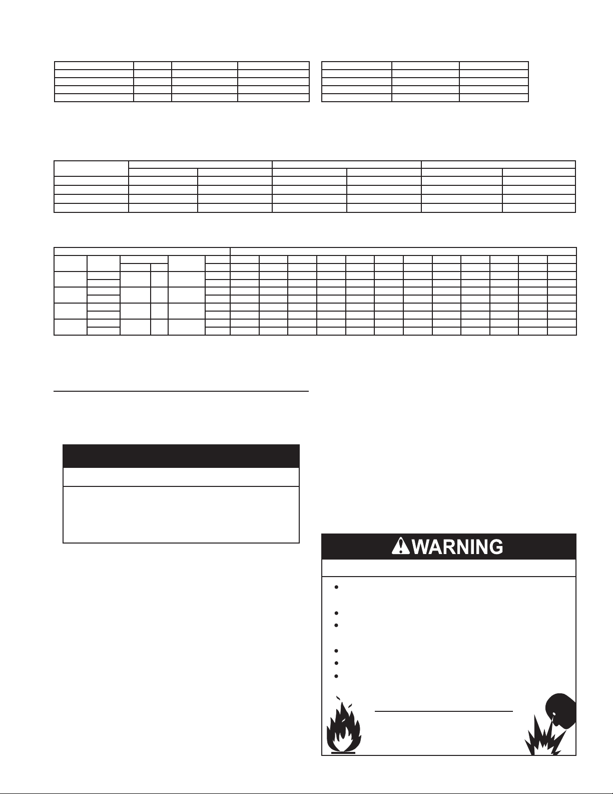
ROUGH IN DIMENSIONS
INSTALLATION CONSIDERATIONS
INTAKE AIR
CONNECTION
3 INCH PVC
WATER
OUTLET
HEIGHT
SUPPLY GAS
CONNECTION
T & P VALV E
D
LOWER
TEMPERATURE
PROBE
CLEANOUT
C
FRONT
3/4” NPT
RECIRCULATION
RETURN
1 1/2” NPT
WATER
INLET
B
VENT
CONNECTION
3 INCH PVC
(exhaust elbow)
3/4” NPT
DRAIN
BACK
E E
I
H
J
G
A
These designs comply with the current edition of the American National Standard for Gas Water Heaters, Volume III, ANSI Z21.10.3 / CSA 4.3
as an automatic circulating tank water heater, and automatic storage water heaters.
TOP VIEW
ALL MODELS
GAS
90°
AIR INTAKE
26°
F
MODEL
BTH 120
BTH 150
BTH 199
BTH 250
1½" NPT WATER
OUTLET
FRONT
42°
EXHAUST
SHIP
WEIGHT
STD
SHIP
WEIGHT
ASME
DRAIN
VALVE
CLEAN OUT
T&P VALVE
30°
45°
* Center line of water outlet on top of the water heaters is approximately 7 inches from the front edge of the water heater.
18°
DIMENSIONS
A B C D E F G H I J
INCHES/CM INCHES/CM INCHES/CM INCHES/CM INCHES/CM INCHES/CM INCHES/CM INCHES/CM INCHES/CM INCHES/CM LBS/KG LBS/KG
3/7.62 27.75/70.5 6.3/16 35/88.9 55.5/141 53.5/135.9 11.25/28.6 42.25/107.32 48.5/123.2 18.25/46.36 460/208 490/220
3/7.62 27.75/70.5 6.3/16 56.38/143.2 76/193.04 75.75/192.4 11.25/28.6 64/162.6 70/177.8 18.25/46.36 523/237 553/251
3/7.62 27.75/70.5 6.3/16 56.38/143.2 76/193.04 75.75/192.4 11.25/28.6 64/162.6 70/177.8 18.25/46.36 523/237 553/251
3/7.62 27.75/70.5 6.3/16 56.38/143.2 76/193.04 75.75/192.4 11.25/28.6 64/162.6 70/177.8 18.25/46.36 523/237 553/251
Figure 5
10
GAS LINE CONNECTION SIZE
CAUTION
TABLE 1
† MODEL SERIES NATURAL GAS PROPANE GAS
BTH 120 200/201 3/4 "NPT 3/4 "NPT
BTH 150 200/201 3/4 "NPT 3/4 "NPT
BTH 199 200/201 3/4 "NPT 3/4 "NPT
BTH 250 200/201 3/4 "NPT 3/4 "NPT
† Depending on the installed equivalent length, and/or the number of appliances connected, the
supply gas line size may have to be increased beyond the minimum required sizes - see Gas
Line Sizing on page 40.
STORAGE CAPACITIES
TABLE 2
MODEL U. S. GALLONS LITERS
BTH 120 60 227
BTH 150 100 379
BTH 199 100 379
BTH 250 100 379
GAS PRESSURE REQUIREMENTS
TABLE 3
MODEL
BTH 120 0" W.C. (0 kPa) 0" W.C. (0 kPa) 4.4” W. C. (1.10 kPa) 8.5” W. C. (2.12 kPa) 14” W. C. (3.49 kPa) 14” W. C. (3.49 kPa)
BTH 150 0" W.C. (0 kPa) 0" W.C. (0 kPa) 4.4” W. C. (1.10 kPa) 8.5” W. C. (2.12 kPa) 14” W. C. (3.49 kPa) 14” W. C. (3.49 kPa)
BTH 199 0” W. C. (0 kPa) 0” W. C. (0 kPa) 4.4” W. C. (1.10 kPa) 8.5” W. C. (2.12 kPa) 14” W. C. (3.49 kPa 14” W. C. (3.49 kPa)
BTH 250 0” W. C. (0 kPa) 0” W. C. (0 kPa) 4.4” W. C. (1.10 kPa) 8.5” W. C. (2.12 kPa) 14” W. C. (3.49 kPa) 14” W. C. (3.49 kPa)
NATURAL GAS PROPANE GAS NATURAL GAS PROPANE GAS NATURAL GAS PROPANE GAS
MANIFOLD PRESSURE MINIMUM SUPPLY PRESSURE MAXIMUM SUPPLY PRESSURE
RECOVERY CAPACITIES
TABLE 4
U. S. GALLONS/HR & LITERS/HR AT TEMPERATURE RISE INDICATED
Model
BTH 120
BTH 150
BTH 199
BTH 250
Type of
Gas
Natural
Propane LPH 1743 1308 1046 872 747 654 581 523 475 436 402 374
Natural
Propane LPH 2248 1686 1349 1124 963 843 749 674 613 562 519 482
Natural
Propane LPH 2965 2224 1779 1483 1271 1112 988 890 809 741 684 635
Natural
Propane LPH 3670 2753 2202 1835 1573 1376 1223 1101 1001 918 847 786
Input
Btu/hr kW °C 17°C 22°C 28°C 33°C 39°C 44°C 50°C 56°C 61°C 67°C 72°C 78°C
120,000 35 95
150,000 44 98
199,900 58 97
250,000 73 96
Thermal
Efciency%
°F 30°F 40°F 50°F 60°F 70°F 80°F 90°F 100°F 110°F 120°F 130°F 140°F
GPH 461 345 276 230 197 173 154 138 126 11 5 106 99
GPH 594 445 356 297 255 223 198 178 162 148 137 127
GPH 783 588 470 392 336 294 261 235 214 196 181 168
GPH 970 727 582 485 416 364 323 291 264 242 224 208
LOCATING THE WATER HEATER
Carefully choose a location for the new water heater. The
placement is a very important consideration for the safety of the
occupants in the building and for the most economical use of the
water heater.
Property Damage Hazard
All water heaters eventually leak.
•
Do not install without adequate drainage.
•
Whether replacing an existing water heater or installing the water
heater in a new location observe the following critical points:
1. The water heater must be located indoors.
2. The water heater must not be located in an area where it will
be subject to freezing temperatures.
3. Locate the water heater so it is protected and not subject to
physical damage by a moving vehicle.
4. Locate the water heater on a level surface.
5. Locate the water heater near a oor drain. The water heater should
be located in an area where leakage of the tank or connections
will not result in damage to the area adjacent to the water heater
or to lower oors of the structure. When such locations cannot be
avoided, it is recommended that a metal drain pan, adequately
drained, be installed under the water heater.
6. Locate the water heater close to the point of major hot water usage.
7. Locate the water heater close to a 120 VAC power supply.
See Power Supply on page 13 for requirements.
8. Locate the water heater where an adequate supply of fresh
air for combustion and ventilation can be obtained. See Air
Requirements on page 17.
9. Locate the water heater where the vent and intake air piping,
when installed, will remain within the maximum equivalent
lengths allowed. See Venting Requirements on page 22.
10. Do not locate the water heater where noise (such as
the Combustion Blower) during normal operation will be
objectionable in adjacent areas.
11. Do not locate the water heater where the subsequent
installation of the vent (exhaust) or intake air terminations
would be objectionable due to noise at the termination(s).
This includes locations close to or across from windows and
doors. See Venting Installation on page 21.
Fire or Explosion Hazard
Do not store or use gasoline or other flammable vapors and
liquids in the vicinity of this or any other appliance.
Avoid all ignition sources if you smell gas.
Do not expose water heater controls to excessive gas
pressure.
Use only the gas shown on the water heater rating label.
Maintain required clearances to combustibles.
Keep ignition sources away from faucets after extended
periods of non-use.
Read instruction manual before
installing, using or servicing
water heater.
11
There is a risk in using fuel burning appliances such as gas
water heaters in rooms, garages or other areas where gasoline,
other ammable liquids or engine driven equipment or vehicles
are stored, operated or repaired. Flammable vapors are heavy
and travel along the oor and may be ignited by the water
heater’s igniter or Main Burner ames causing re or explosion.
Flammable items, pressurized containers or any other potential
re hazardous articles must never be placed on or adjacent to
the water heater.
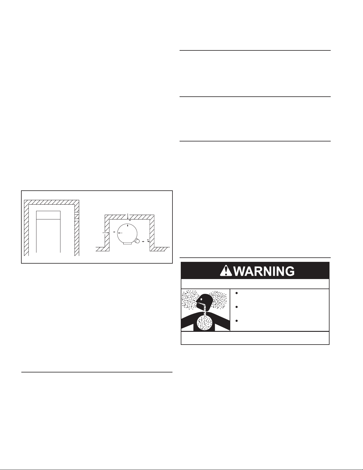
CLEARANCE TO COMBUSTIBLE MATERIALS
The water heaters covered in this manual are approved for
installation on combustible ooring. The clearance to combustible
and non combustible construction materials is 0 inches on the
back and sides of the water heater. These water heaters are also
approved for installation in an alcove.
When the water heater is installed directly on carpeting, the water
heater shall be installed on a metal or wood panel extending
beyond the full width and depth of the water heater by at least
3 in (76.2 mm) in any direction or, if the water heater is installed
in an alcove or closet, the entire oor shall be covered by the
panel. The panel must be strong enough to carry the weight of
the heater when full of water.
NOTE: Adequate clearance for servicing should be maintained
on all installations. See Service Clearance below.
ALCOVE
TOP COVER
WATER
HEATER
FRONT
FRONT VIEW
CLEARANCES TO COMBUSTIBLE
AND NON COMBUSTIBLE
CONSTRUCTION MATERIALS
0
0
0
FRONT
TOP VIEW
Contact your local distributor or call the parts department phone
number listed on the back cover of this manual to order 4 inch
termination(s).
OPTIONAL CONCENTRIC & LOW PROFILE TERMINATIONS
The water heaters covered in this manual can be installed in
a Direct Vent conguration using optional concentric or Low
Prole terminations. See Concentric Termination Installation
on page 30 and Low Prole Vent Termination Installation on
page 34.
HARD WATER
Where hard water conditions exist, water softening or the
threshold type of water treatment is recommended. This will
protect the dishwashers, coffee urns, water heaters, water
piping and other equipment. See Maintenance on page 63 for
sediment and lime scale removal procedures.
CIRCULATION PUMPS
A circulating pump is used when a system requires a circulating
loop or there is a storage tank used in conjunction with the water
heater. The tank is provided with a 3/4" NPT recirculation loop
return connection. See the Water Piping Diagrams beginning on
page 69 for installation location of circulating pumps.
See Circulation Pump Wiring Diagrams on page 68 for
electrical hookup information. Install in accordance with the
current edition of the National Electrical Code, NFPA 70 or the
Canadian Electrical Code, CSA C22.1.
Stainless steel circulating pumps are recommended for use with
commercial water heaters.
Some circulating pumps are manufactured with sealed bearings
and do not require further lubrication. Some circulating pumps
must be periodically oiled. Refer to the pump manufacturer’s
instructions for lubrication requirements.
INSULATION BLANKETS
Figure 6
SERVICE CLEARANCE
A service clearance of 24 inches (61 cm) should be maintained
from serviceable parts such as the T&P valve, control system
components, gas valve, clean out opening, drain valve, the vent
connection (exhaust/condensate elbow). Leave as much room as
possible above the water heater and near the exhaust elbow for
this reason. See Figure 8 on page 16.
INTAKE AIR AND VENT PIPE CLEARANCES
The minimum clearance from combustible materials for the vent
(exhaust) and intake air piping shall be 0 inches. Vent or intake
air piping passing through a combustible wall or ceiling must be
a continuous run (no joints).
EXTENDED VENT TERMINATIONS
The water heaters covered by this manual can be installed using
3 inch pipe for the intake air and/or vent piping up to a maximum
of 50 equivalent feet (15.2 m). The intake air and/or vent piping
can be extended up to 120 equivalent feet (36.5 m) by installing
4 inch pipe. See the Venting Requirements on page 22.
The water heater ships from the factory with two (2) 3 inch
terminations that are 45° PVC elbows with a debris screen
installed. When 4 inch intake air or vent pipe is installed, factory
supplied 4 inch terminations must be used.
Breathing Hazard - Carbon Monoxide Gas
Do not obstruct water heater air intake
with insulating blanket.
Gas and carbon monoxide detectors
are available.
Install water heater in accordance with
the instruction manual.
Breathing carbon monoxide can cause brain damage or
death. Always read and understand instruction manual.
Insulation blankets are available to the general public for
external use on gas water heaters but are not necessary
with these products. The purpose of an insulation blanket is
to reduce the standby heat loss encountered with storage
tank heaters. The water heaters covered by this manual meet
or exceed the Energy Policy Act standards with respect to
insulation and standby heat loss requirements, making an
insulation blanket unnecessary.
Should you choose to apply an insulation blanket to this
heater, you should follow these instructions. See the Features
and Components section of this manual for identication
of components mentioned below. Failure to follow these
instructions can restrict the air ow required for proper
12

combustion, potentially resulting in re, asphyxiation, serious
personal injury or death.
• DO NOT apply insulation to the top of the water heater, as
this will interfere with safe operation of the blower assembly.
• DO NOT cover the control system LCD on top of the water
heater.
• DO NOT cover the Temperature-Pressure Relief Valve.
INSTALLATION REQUIREMENTS
• DO NOT cover the instruction manual. Keep it on the side of
the water heater or nearby for future reference.
• DO obtain new warning and instruction labels from the
manufacturer for placement on the blanket directly over the
existing labels.
• DO inspect the insulation blanket frequently to make certain it
does not sag, thereby obstructing combustion air ow.
GAS SUPPLY SYSTEMS
Low pressure building gas supply systems are dened as
those systems that cannot under any circumstances exceed
14” W.C. (1/2 PSI Gauge). These systems do not require
pressure regulation. Measurements should be taken to insure
that gas pressures are stable and fall within the requirements
stated on the water heater rating plate. Readings should be
taken with all gas burning equipment off (static pressure)
and with all gas burning equipment running at maximum rate
(dynamic pressure). The gas supply pressure must be stable
within 1.5” W.C. from static to dynamic pressure to provide
good performance. Pressure drops that exceed 1.5” W.C. may
cause rough starting, noisy combustion or nuisance outages.
Increases or spikes in static pressure during off cycles may
cause failure to ignite or in severe cases damage to appliance
gas valves. If your low pressure system does NOT meet these
requirements, the installer is responsible for the corrections.
High Pressure building supply systems use pressures that
exceed 14” W.C. (1/2 PSI Gauge). These systems must use
eld supplied regulators to lower the gas pressure to less than
14” W.C. (1/2 PSI Gauge). Water heaters require gas regulators
that are properly sized for the water heater input and deliver
the rating plate specied pressures. Gas supply systems where
pressure exceeds 5 PSI often require multiple regulators to
achieve desired pressures. Systems in excess of 5 PSI building
pressure should be designed by gas delivery professionals
for best performance. Water heaters connected to gas supply
systems that exceed 14” W.C. (1/2 PSI Gauge) at any time
must be equipped with a gas supply regulator.
All models require a minimum gas supply pressure of 4.4" W.C.
for natural gas and 8.5" W.C. for propane gas. The minimum
supply pressure is measured while gas is owing (dynamic
pressure). The supply pressure should never fall below 4.4"
W.C. for natural gas and 8.5" W.C. for propane gas. The supply
pressure should be measured with all gas red appliances
connected to the common main ring at full capacity. If the supply
pressure drops more than 1.5” W.C. as gas begins to ow to
the water heater then the supply gas system including the gas
line and/or the gas regulator may be restricted or undersized.
See Supply Gas Regulator section and Gas Piping section of
this manual. The gas valve on all models has a maximum gas
supply pressure limit of 14” W.C. The maximum supply pressure
is measured while gas is not owing (static pressure).
SUPPLY GAS REGULATOR
The maximum allowable gas supply pressure for this water
heater is 14.0 inches W.C. (3.49 kPa) for natural and propane
gas. Install a positive lock-up gas pressure regulator in the gas
supply line if inlet gas pressure can exceed these pressures at
any time.
If a positive lock-up regulator is required follow these instructions:
1. Positive lock-up gas pressure regulators must be rated
at or above the input Btu/hr rating of the water heater
they supply.
2. Supply gas regulators shall have inlet and outlet connections
not less than the minimum supply gas line size for the water
heater they supply. See Table 11, page 40.
3. Positive lock-up gas pressure regulator(s) should be installed
no closer than 3 feet (1 meter) and no farther than 8 feet (2.4
meters) from the water heater’s inlet gas connection.
4. After installing the positive lock-up gas pressure regulator(s)
an initial nominal supply pressure setting of 7.0” W.C.
while the water heater is operating is recommended and
will generally provide good water heater operation. Some
addition adjustment maybe required later to maintain a
steady gas supply pressure.
5. When installing multiple water heaters in the same gas
supply system it is recommended that individual positive
lock-up gas pressure regulators be installed at each unit
from the supply gas connection on the water heater.
POWER SUPPLY
The water heaters covered in this manual require a 120 VAC,
1Ø (single phase), 60Hz, 15 amp power supply and must also
be electrically grounded in accordance with local codes or, in
the absence of local codes, with the National Electrical Code,
ANSI/NFPA 70 or the Canadian Electrical Code, CSA C22.1.
DEDICATED POWER WIRING AND BREAKERS
Dedicated power supply wires, ground wiring and dedicated
circuit breakers often prevent electrical line noise and are
required when installing the water heater.
POWER FLUCTUATIONS AND ELECTRICAL NOISE
The water heater’s control system requires a source of
stable clean electricity for proper operation. Connecting the
water heater to a branch circuit that is subject to uctuations
in voltage level or electrical line noise such as EMI (electro
magnetic interference) or RFI (radio frequency interference)
may cause erratic control system operation and malfunction.
A high quality power supply lter/suppressor such as the
Kleen Line model SELF/T-10 Series SC-L or equivalent must
be installed if the above conditions exist. Call the technical
support phone number listed on the back cover of this manual
for more information.
NOTE: Malfunctions caused by the power supply and costs to
install power supply lters are not covered under the limited
warranty.
13
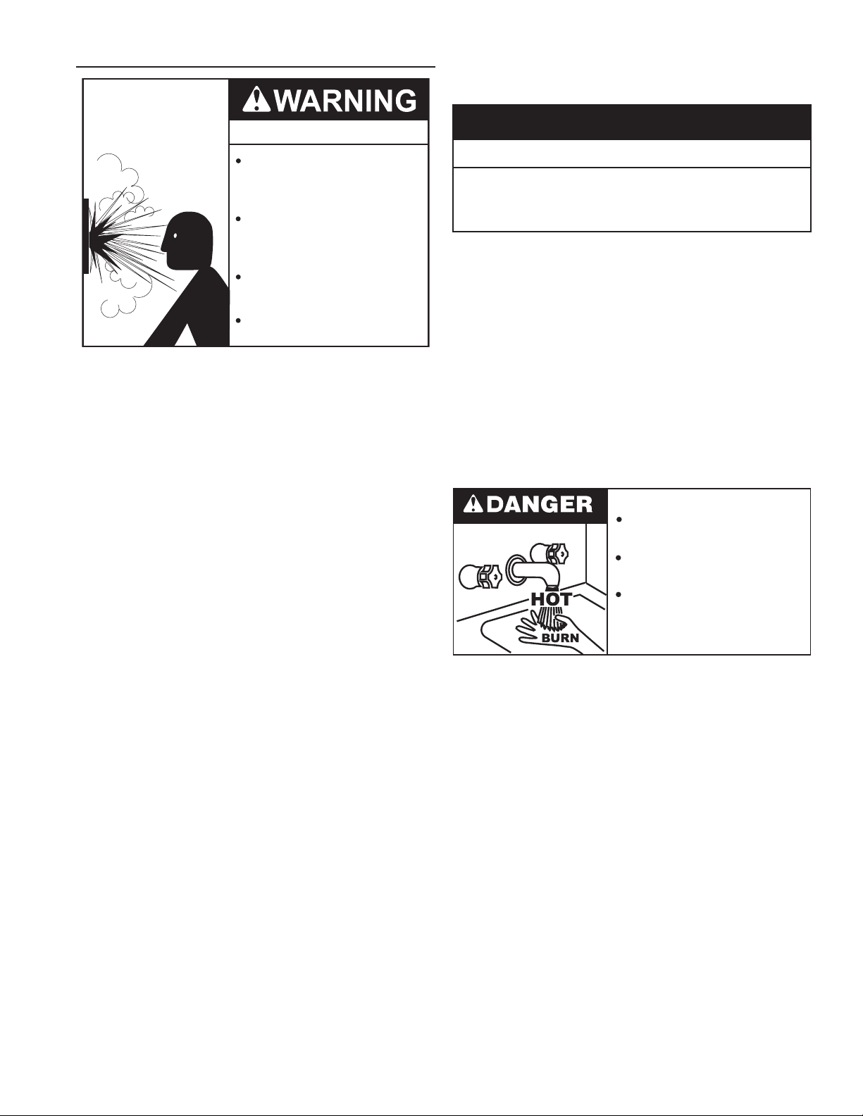
MIXING VALVES
Water temperature over 125°F (52°C)
can cause severe burns instantly
resulting in severe injury or death.
Children, the elderly and the
physically or mentally disabled are at
highest risk for scald injury.
Feel water before bathing or
showering.
Temperature limiting devices such as
mixing valves must be installed
when required by codes and to
ensure safe temperatures at fixtures.
Water heated to a temperature which will satisfy clothes washing,
dish washing, and other sanitizing needs can scald and cause
permanent injury upon contact. Short repeated heating cycles
caused by small hot water uses can cause temperatures at the
point of use to exceed the water heater’s temperature setting by
up to 20°F (11°C).
Some people are more likely to be permanently injured by
hot water than others. These include the elderly, children, the
inrm and the physically/mentally disabled. Table 5 shows the
approximate time-to-burn relationship for normal adult skin.
If anyone using hot water provided by the water heater being
installed ts into one of these groups or if there is a local code
or state law requiring a certain water temperature at the point of
use, then special precautions must be taken.
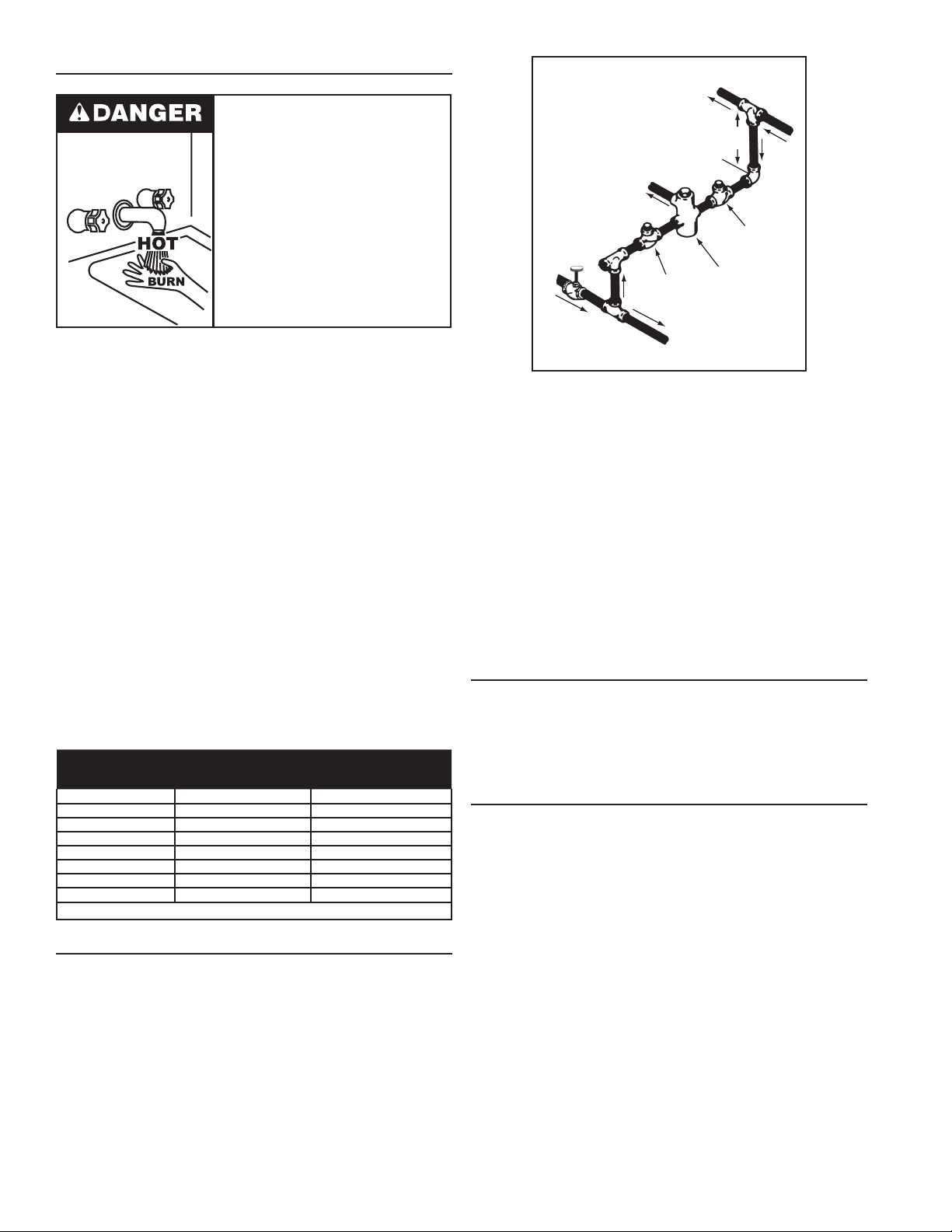
In addition to using the lowest possible temperature setting that
satises the demand of the application a Mixing Valve should be
installed at the water heater (see Figure 7) or at the hot water
taps to further reduce system water temperature.
Mixing valves are available at plumbing supply stores. Consult
a Qualied Installer or Service Agency. Follow mixing valve
manufacturer’s instructions for installation of the valves.
TABLE 5
Water Temperature
°F (°C)
110 (43) (normal shower temp.)
116 (47) (pain threshold)
116 (47) 35 minutes 45 minutes
122 (50) 1 minute 5 minutes
131 (55) 5 seconds 25 seconds
140 (60) 2 seconds 5 seconds
149 (65) 1 second 2 seconds
154 (68) instantaneous 1 second
(U.S. Government Memorandum, C.P.S.C., Peter L. Armstrong, Sept. 15, 1978)
Time for 1st Degree Burn
(Less Severe Burns)
Time for Permanent Burns
2nd & 3rd Degree
(Most Severe Burns)
DISHWASHING MACHINES
All dishwashing machines meeting the National Sanitation
Foundation requirements are designed to operate with water
ow pressures between 15 and 25 pounds per square inch (103
kPa and 173 kPa). Flow pressures above 25 pounds per square
inch (173 kPa), or below 15 pounds per square inch (103 kPa),
will result in improperly sanitized dishes. Where pressures are
high, a water pressure reducing or ow regulating control valve
should be used in the 180°F (82°C) line to the dishwashing
machine and should be adjusted to deliver water pressure
between these limits.
HOT WATER
OUTLET
12” TO 15”
(30-38 cm)
TEMPERED WATER
OUTLET
COLD
WATER
INLET
CHECK
VALV E
TO TANK
INLET
CHECK
VALV E
MIXING
VALV E
Figure 7
The National Sanitation Foundation also recommends circulation
of 180°F (82°C) water. Where this is done, the circulation should
be very gentle so that it does not cause any unnecessary
turbulence inside the water heater. The circulation should be just
enough to provide 180°F (82°C) water at the point of take-off to
the dishwashing machine.
Adjust ow by throttling a full port ball valve installed in the
circulating line on the outlet side of the pump. Never throttle ow
on the suction side of a pump. See the Water Piping Diagrams
beginning on page 69.
NOTE: To comply with NSF Standard 5 installation requirements
the bottom of the water heater must be sealed to the oor with a
silicone based sealant or elevated 6 inches above the oor.
CLOSED WATER SYSTEMS
Water supply systems may, because of code requirements
or such conditions as high line pressure, among others, have
installed devices such as pressure reducing valves, check
valves, and back ow preventers. Devices such as these cause
the water system to be a closed system.
THERMAL EXPANSION
As water is heated, it expands (thermal expansion). In a
closed system the volume of water will grow when it is heated.
As the volume of water grows there will be a corresponding
increase in water pressure due to thermal expansion. Thermal
expansion can cause premature tank failure (leakage). This
type of failure is not covered under the limited warranty.
Thermal expansion can also cause intermittent TemperaturePressure Relief Valve operation: water discharged from the
valve due to excessive pressure build up. This condition is
not covered under the limited warranty. The TemperaturePressure Relief Valve is not intended for the constant relief
of thermal expansion.
A properly sized thermal expansion tank must be installed on
all closed systems to control the harmful effects of thermal
expansion. Contact a local plumbing service agency to have a
thermal expansion tank installed.
See Water Line Connections on page 43 and the Water Piping
Diagrams beginning on page 69.
14
CAUTION
TEMPERATURE-PRESSURE RELIEF VALVE
Explosion Hazard
Temperature-Pressure Relief Valve
must comply with ANSI Z21.22CSA 4.4 and ASME code.
Properly sized temperaturepressure relief valve must be
installed in opening provided.
Can result in overheating and
excessive tank pressure.
Can cause serious injury or death.
This water heater is provided with a properly rated/sized and
certied combination Temperature-Pressure Relief Valve (T&P
valve) by the manufacturer. The valve is certied by a nationally
recognized testing laboratory that maintains periodic inspection
of production of listed equipment of materials as meeting the
requirements for Relief Valves for Hot Water Supply Systems,
ANSI Z21.22 • CSA 4.4, and the code requirements of ASME.
If replaced, the new T&P valve must meet the requirements
of local codes, but not less than a combination TemperaturePressure Relief Valve rated/sized and certied as indicated in
the above paragraph. The new valve must be marked with a
maximum set pressure not to exceed the marked hydrostatic
working pressure of the water heater (150 psi = 1,035 kPa) and
a discharge capacity not less than the water heater Btu/hr or kW
input rate as shown on the water heater’s model rating label.
NOTE: In addition to the factory installed Temperature-Pressure
Relief Valve on the water heater, each remote storage tank that
may be installed and piped to a water heating appliance must also
have its own properly sized, rated and approved TemperaturePressure Relief Valve installed. Call the toll free technical
support phone number listed on the back cover of this manual
for technical assistance in sizing a Temperature-Pressure Relief
Valve for remote storage tanks.
For safe operation of the water heater, the Temperature-Pressure
Relief Valve must not be removed from its designated opening
nor plugged. The Temperature-Pressure Relief Valve must be
installed directly into the tting of the water heater designed for the
relief valve. Install discharge piping so that any discharge will exit
the pipe within 6 inches (15.2 cm) above an adequate oor drain,
or external to the building. In cold climates it is recommended
that it be terminated at an adequate drain inside the building. Be
certain that no contact is made with any live electrical part. The
discharge opening must not be blocked or reduced in size under
any circumstances. Excessive length, over 30 feet (9.14 m), or
use of more than four elbows can cause restriction and reduce
the discharge capacity of the valve.
No valve or other obstruction is to be placed between the
Temperature-Pressure Relief Valve and the tank. Do not connect
discharge piping directly to the drain unless a 6” (15.2 cm)
air gap is provided. To prevent bodily injury, hazard to life, or
property damage, the relief valve must be allowed to discharge
water in adequate quantities should circumstances demand. If
the discharge pipe is not connected to a drain or other suitable
means, the water ow may cause property damage.
Water Damage Hazard
Temperature-Pressure Relief Valve discharge
•
pipe must terminate at adequate drain.
T&P Valve Discharge Pipe Requirements:
• Shall not be smaller in size than the outlet pipe size of the
valve, or have any reducing couplings or other restrictions.
• Shall not be plugged or blocked.
• Shall not be exposed to freezing temperatures.
• Shall be of material listed for hot water distribution.
• Shall be installed so as to allow complete drainage of both the
Temperature-Pressure Relief Valve and the discharge pipe.
• Must terminate a maximum of six inches above a oor drain
or external to the building. In cold climates, it is recommended
that the discharge pipe be terminated at an adequate drain
inside the building.
• Shall not have any valve or other obstruction between the
relief valve and the drain.
Burn hazard.
Hot water discharge.
Keep clear of TemperaturePressure Relief Valve
discharge outlet.
The Temperature-Pressure Relief Valve must be manually
operated at least twice a year. Caution should be taken to
ensure that (1) no one is in front of or around the outlet of the
Temperature-Pressure Relief Valve discharge line, and (2) the
water manually discharged will not cause any bodily injury or
property damage because the water may be extremely hot. If
after manually operating the valve, it fails to completely reset
and continues to release water, immediately close the cold water
inlet to the water heater, follow the draining instructions in this
manual, and replace the Temperature-Pressure Relief Valve with
a properly rated/sized new one.
NOTE: The purpose of a Temperature-Pressure Relief Valve is
to prevent excessive temperatures and pressures in the storage
tank. The T&P valve is not intended for the constant relief of
thermal expansion. A properly sized thermal expansion tank must
be installed on all closed systems to control thermal expansion,
see Closed Water Systems and Thermal Expansion on page 14.
If you do not understand these instructions or have any
questions regarding the Temperature-Pressure Relief Valve call
the toll free number listed on the back cover of this manual for
technical assistance.
15
CONDENSATE DRAIN
The water heaters covered in this manual are condensing
appliances and require a building drain to be located in close
proximity to allow the condensate to drain safely.
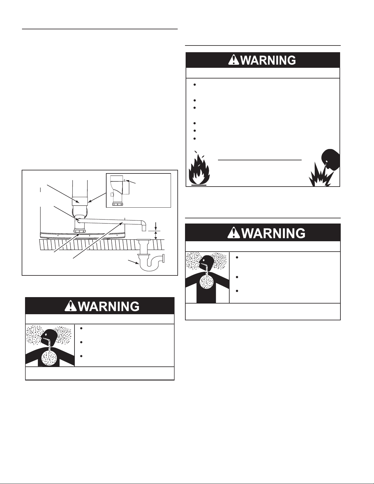
Condensate drains from the water heater at the exhaust elbow
located at the bottom. The eld installed condensate drain line
must not be elevated above the condensate drain connection
on the condensate trap, see Figure 8. If the condensate does
not drain properly it will build up in the exhaust (vent) elbow.
This will restrict the ow of ue gases and cause the Blocked
Exhaust pressure switch to open its contacts. The control system
monitors all pressure switches, if the Blocked Exhaust Switch
contacts are open the control system will lock out and disable
heating operation. The “Blocked Exhaust” Fault message will
be displayed on the control system’s LCD, see Fault And Alert
Conditions beginning on page 60.
The Condensate Cleanout Cap must be on and tight when unit
is in operation.
NOTE: If the “Blocked Exhaust “ Fault message is ever displayed
on the control system LCD, check the condensate drain rst and
ensure it is not blocked.
EXHAUST (VENT)
ELBOW
CONDENSATE
DRAIN LINE
CONNECTION
DRAIN LINE TO TERMINATE NO
MORE THAN 6 INCHES (15.2cm)
THIS SIDE VIEW
OF EXHAUST
ELBOW AND
ARROW INDICATE
THE LOCATION OF
THE PRESSURE
PORT
ABOVE DRAIN
line, such as copper, to the water heater for this reason. See
Condensate Drain Installation on page 39.
COMBUSTIBLE MATERIAL STORAGE
Fire or Explosion Hazard
Do not store or use gasoline or other flammable vapors and
liquids in the vicinity of this or any other appliance.
Avoid all ignition sources if you smell gas.
Do not expose water heater controls to excessive gas
pressure.
Use only the gas shown on the water heater rating label.
Maintain required clearances to combustibles.
Keep ignition sources away from faucets after extended
periods of non-use.
Read instruction manual before
installing, using or servicing
water heater.
Keep water heater area clear and free of combustible materials,
gasoline and other ammable vapors and liquids.
CONTAMINATED AIR
CONDENSATE
CLEANOUT CAP
CONDENSATE DRAIN
LINE - FIELD INSTALLED
BUILDING
DRAIN
Figure 8
CONDENSATE DRAIN WATER TRAP
Breathing Hazard - Carbon Monoxide Gas
Ensure a functioning water trap is
installed in the condensate drain.
Gas and carbon monoxide detectors
are available.
Install water heater in accordance with
the instruction manual.
Breathing carbon monoxide can cause brain damage or
death. Always read and understand instruction manual.
DO NOT remove the factory installed exhaust/condensate elbow
for any reason, see Figure 8. The water heater’s vent pipe is
under a slight positive pressure while unit is in operation. The
water trap inside of the exhaust/condensate elbow prevents ue
gases from escaping into the installed space. See Condensate
Drain Installation on page 39.
CONDENSATE PH LEVEL
The condensate drains from the water heater’s covered in
this manual have PH levels between 4.3 and 5.0. Install a
commercially available neutralizing kit if required by local codes.
NOTE: Lower PH levels are acidic. Do not connect a metal drain
Breathing Hazard - Carbon Monoxide Gas
Install water heater in accordance with
the Instruction Manual and NFPA 54 or
CAN/CSA-B149.1.
To avoid injury, combustion and ventilation
air must be taken from outdoors.
Do not place chemical vapor emitting
products near water heater.
Breathing carbon monoxide can cause brain damage or
death. Always read and understand instruction manual.
Corrosion of the ue ways and vent system may occur if air for
combustion contains certain chemical vapors. Such corrosion
may result in failure and risk of asphyxiation.
Combustion air that is contaminated can greatly diminish the
life span of the water heater and water heater components such
as igniters and burners. Propellants of aerosol sprays, beauty
shop supplies, water softener chemicals and chemicals used
in dry cleaning processes that are present in the combustion,
ventilation or ambient air can cause such damage.
Do not store products of this sort near the water heater. Air which
is brought in contact with the water heater should not contain any
of these chemicals. If necessary, uncontaminated air should be
obtained from remote or outdoor sources. The limited warranty is
voided when failure of water heater is due to a corrosive atmosphere.
(See limited warranty for complete terms and conditions).
If the water heater will be used in beauty shops, barber shops,
cleaning establishments, or self-service laundries with dry
cleaning equipment, it is imperative that the water heater(s) be
installed in a Direct Vent conguration so that all air for combustion
is derived directly from the outdoor atmosphere through a sealed
intake air pipe. See Venting Installation on page 21.
16
AIR REQUIREMENTS
Breathing Hazard - Carbon Monoxide Gas
Install water heater in accordance with
the Instruction Manual and NFPA 54 or
CAN/CSA-B149.1.
To avoid injury, combustion and ventilation
air must be taken from outdoors.
Do not place chemical vapor emitting
products near water heater.
Breathing carbon monoxide can cause brain damage or
death. Always read and understand instruction manual.
For safe operation an adequate supply of fresh uncontaminated
air for combustion and ventilation must be provided.
An insufcient supply of air can cause recirculation of
combustion products resulting in contamination that may be
hazardous to life. Such a condition often will result in a yellow,
luminous burner ame, causing sooting of the combustion
chamber, burners and ue tubes and creates a risk of
asphyxiation.
Do not install the water heater in a conned space unless an
adequate supply of air for combustion and ventilation is brought
in to that space using the methods described in the Conned
Space section that follows.
Never obstruct the ow of ventilation air. If you have any doubts
or questions at all, call your gas supplier. Failure to provide the
proper amount of combustion air can result in a re or explosion
and cause property damage, serious bodily injury or death.
UNCONFINED SPACE
An Unconned Space is one whose volume IS NOT LESS THAN
50 cubic feet per 1,000 Btu/hr (4.8 cubic meters per kW) of the
total input rating of all appliances installed in the space. Rooms
communicating directly with the space, in which the appliances
are installed, through openings not furnished with doors, are
considered a part of the unconned space.
Makeup air requirements for the operation of exhaust fans,
kitchen ventilation systems, clothes dryers and replaces shall
also be considered in determining the adequacy of a space to
provide combustion, ventilation and dilution air.
UNUSUALLY TIGHT CONSTRUCTION
In unconned spaces in buildings, inltration may be adequate
to provide air for combustion, ventilation and dilution of ue
gases. However, in buildings of unusually tight construction (for
example, weather stripping, heavily insulated, caulked, vapor
barrier, etc.) additional air must be provided using the methods
described in the Conned Space section that follows.
CONFINED SPACE
A Conned Space is one whose volume IS LESS THAN 50 cubic
feet per 1,000 Btu/hr (4.8 cm per kW) of the total input rating of
all appliances installed in the space.
Openings must be installed to provide fresh air for combustion,
ventilation and dilution in conned spaces. The required size for
the openings is dependent on the method used to provide fresh
air to the conned space AND the total Btu/hr input rating of all
appliances installed in the space.
DIRECT VENT APPLIANCES
Appliances installed in a Direct Vent conguration that derive all
air for combustion from the outdoor atmosphere through sealed
intake air piping are not factored in the total appliance input Btu/
hr calculations used to determine the size of openings providing
fresh air into conned spaces.
EXHAUST FANS
Where exhaust fans are installed, additional air shall be provided
to replace the exhausted air. When an exhaust fan is installed
in the same space with a water heater, sufcient openings to
provide fresh air must be provided that accommodate the
requirements for all appliances in the room and the exhaust fan.
Undersized openings will cause air to be drawn into the room
through the water heater’s vent system causing poor combustion.
Sooting, serious damage to the water heater and the risk of re
or explosion may result. It can also create a risk of asphyxiation.
LOUVERS AND GRILLES
The free areas of the fresh air openings in the instructions that
follow do not take in to account the presence of louvers, grilles or
screens in the openings.
The required size of openings for combustion, ventilation and
dilution air shall be based on the “net free area” of each opening.
Where the free area through a design of louver or grille or screen
is known, it shall be used in calculating the size of opening
required to provide the free area specied. Where the louver and
grille design and free area are not known, it shall be assumed
that wood louvers will have 25% free area and metal louvers and
grilles will have 75% free area. Non motorized louvers and grilles
shall be xed in the open position.
17
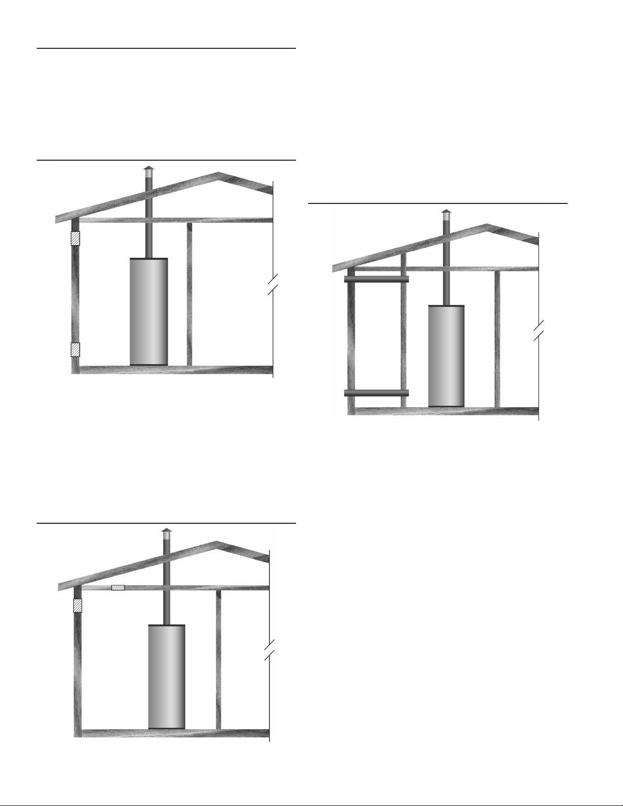
FRESH AIR OPENINGS FOR CONFINED SPACES
The following instructions shall be used to calculate the size,
number and placement of openings providing fresh air for
combustion, ventilation and dilution in conned spaces. The
illustrations shown in this section of the manual are a reference
for the openings that provide fresh air into conned spaces
only. DO NOT refer to these illustrations for the purpose of vent
installation. See Venting Installation on page 21 for complete
venting installation instructions.
OUTDOOR AIR THROUGH TWO OPENINGS
Alternatively a single permanent opening, commencing within 12
inches (300 mm) of the top of the enclosure, shall be provided.
See Figure 10. The water heater shall have clearances of at
least 1 inch (25 mm) from the sides and back and 6 inches (l50
mm) from the front of the water heater. The opening shall directly
communicate with the outdoors or shall communicate through a
vertical or horizontal duct to the outdoors or spaces that freely
communicate with the outdoors and shall have a minimum free
area of the following:
1. 1 square inch per 3000 Btu/hr (733 mm2 per kW) of the total
input rating of all appliances located in the enclosure, and
2. Not less than the sum of the areas of all vent connectors in
the space.
OUTDOOR AIR THROUGH TWO HORIZONTAL DUCTS
Figure 9
The conned space shall be provided with two permanent
openings, one commencing within 12 inches (300 mm) of the top
and one commencing within 12 inches (300 mm) of the bottom of
the enclosure. The openings shall communicate directly with the
outdoors. See Figure 9.
Each opening shall have a minimum free area of 1 square inch
per 4,000 Btu/hr (550 mm2 per kW) of the aggregate input rating
of all appliances installed in the enclosure. Each opening shall
not be less than 100 square inches (645 cm2).
OUTDOOR AIR THROUGH ONE OPENING
Figure 11
The conned space shall be provided with two permanent
horizontal ducts, one commencing within 12 inches (300 mm) of
the top and one commencing within 12 inches (300 mm) of the
bottom of the enclosure. The horizontal ducts shall communicate
directly with the outdoors. See Figure 11.
Each duct opening shall have a minimum free area of 1 square
inch per 2,000 Btu/hr (1100 mm2 per kW) of the aggregate input
rating of all appliances installed in the enclosure.
When ducts are used, they shall be of the same cross sectional
area as the free area of the openings to which they connect.
The minimum dimension of rectangular air ducts shall be not less
than 3 inches.
Figure 10
18
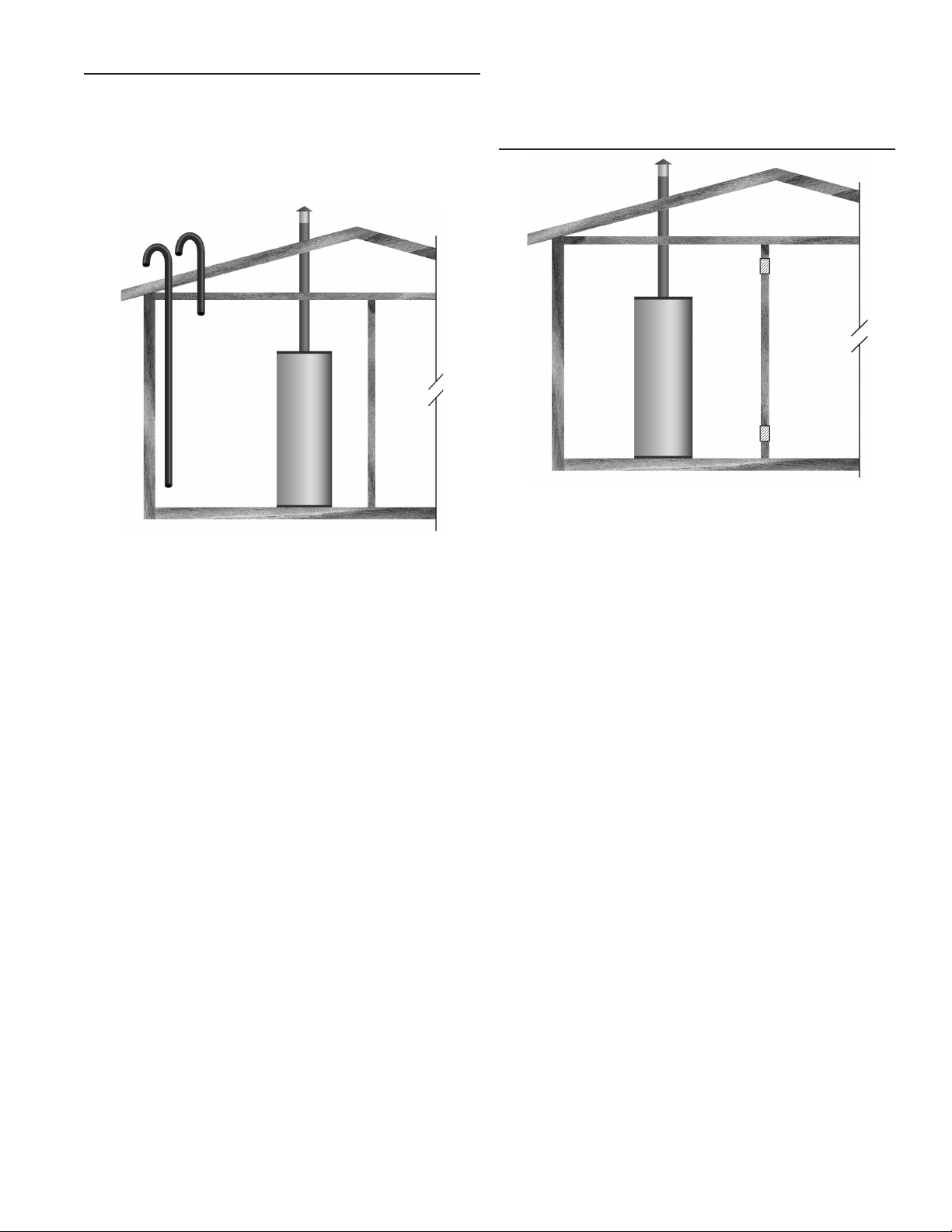
OUTDOOR AIR THROUGH TWO VERTICAL DUCTS
The illustrations shown in this section of the manual are a
reference for the openings that provide fresh air into conned
spaces only.
DO NOT refer to these illustrations for the purpose of vent
installation. See Venting Installation on page 21 for complete
venting installation instructions.
When ducts are used, they shall be of the same cross sectional
area as the free area of the openings to which they connect.
The minimum dimension of rectangular air ducts shall be not less
than 3 inches (7.62 cm).
AIR FROM OTHER INDOOR SPACES
Figure 13
Figure 12
The conned space shall be provided with two permanent vertical
ducts, one commencing within 12 inches (300 mm) of the top and
one commencing within 12 inches (300 mm) of the bottom of the
enclosure. The vertical ducts shall communicate directly with the
outdoors. See Figure 12.
Each duct opening shall have a minimum free area of 1 square
inch per 4,000 Btu/hr (550 mm2 per kW) of the aggregate input
rating of all appliances installed in the enclosure.
The conned space shall be provided with two permanent
openings, one commencing within 12 inches (300 mm) of the top
and one commencing within 12 inches (300 mm) of the bottom of
the enclosure. See Figure 13.
Each opening shall communicate directly with an additional
room(s) of sufcient volume so that the combined volume of all
spaces meets the criteria for an Unconned Space.
Each opening shall have a minimum free area of 1 square inch
per 1,000 Btu/hr (2200 mm2 per kW) of the aggregate input
rating of all appliances installed in the enclosure. Each opening
shall not be less than 100 square inches (645 cm2).
19

INSTALLATION REQUIREMENTS - COMMONWEALTH OF MASSACHUSETTS
COMMONWEALTH OF MASSACHUSETTS
For all side wall terminated, horizontally vented power vent, direct
vent, and power direct vent gas fueled water heaters installed in
every dwelling, building or structure used in whole or in part for
residential purposes, including those owned or operated by the
Commonwealth and where the side wall exhaust vent termination
is less than seven (7) feet above nished grade in the area of
the venting, including but not limited to decks and porches, the
following requirements shall be satised:
INSTALLATION OF CARBON MONOXIDE DETECTORS
At the time of installation of the side wall horizontal vented
gas fueled equipment, the installing plumber or gastter shall
observe that a hard wired carbon monoxide detector with an
alarm and battery back-up is installed on the oor level where
the gas equipment is to be installed. In addition, the installing
plumber or gastter shall observe that a battery operated or
hard wired carbon monoxide detector with an alarm is installed
on each additional level of the dwelling, building or structure
served by the sidewall horizontal vented gas fueled equipment.
It shall be the responsibility of the property owner to secure the
services of qualied licensed professionals for the installation of
hard wired carbon monoxide detectors.
In the event that the side wall horizontally vented gas fueled
equipment is installed in a crawl space or an attic, the hard wired
carbon monoxide detector with alarm and battery back-up may
be installed on the next adjacent oor level.
In the event that the requirements of this subdivision can not
be met at the time of completion of installation, the owner shall
have a period of thirty (30) days to comply with the above
requirements provided that during said thirty (30) day period, a
battery operated carbon monoxide detector with an alarm shall
be installed.
APPROVED CARBON MONOXIDE DETECTORS
Each carbon monoxide detector as required in accordance with
the above provisions shall comply with NFPA 720 and be ANSI/
UL 2034 listed and CSA certied.
SIGNAGE
A metal or plastic identication plate shall be permanently
mounted to the exterior of the building at a minimum height of
eight (8) feet above grade directly in line with the exhaust vent
terminal for the horizontally vented gas fueled heating appliance
or equipment. The sign shall read, in print size no less than onehalf (1/2) inch in size, “GAS VENT DIRECTLY BELOW. KEEP
CLEAR OF ALL OBSTRUCTIONS.”
INSPECTION
The state or local gas inspector of the side wall horizontally
vented gas fueled equipment shall not approve the installation
unless, upon inspection, the inspector observes carbon
monoxide detectors and signage installed in accordance with the
provisions of 248 CMR 5.08(2)(a) 1 through 4.
EXEMPTIONS
The following equipment is exempt from 248 CMR 5.08(2)(a)1
through 4:
1. The equipment listed in Chapter 10 entitled “Equipment Not
Required To Be Vented” in the most current edition of NFPA
54 as adopted by the Board; and
2. Product Approved side wall horizontally vented gas fueled
equipment installed in a room or structure separate from the
dwelling, building, or structure used in whole or in part for
residential purposes.
MANUFACTURER REQUIREMENTS - GAS
EQUIPMENT VENTING SYSTEM PROVIDED
When the manufacturer of Product Approved side wall
horizontally vented gas equipment provides a venting system
design or venting system components with the equipment, the
instructions provided by the manufacturer for installation of the
equipment and the venting system shall include:
1. Detailed instructions for the installation of the venting system
design or the venting system components; and
2. A complete parts list for the venting system design or venting
system.
MANUFACTURER REQUIREMENTS - GAS
EQUIPMENT VENTING SYSTEM NOT PROVIDED
When the manufacturer of a Product Approved side wall
horizontally vented gas fueled equipment does not provide the
parts for venting the ue gases, but identies “special venting
systems,” the following requirements shall be satised by the
manufacturer:
1. The referenced “special venting system” instructions shall
be included with the appliance or equipment installation
instructions; and
2. The “special venting systems” shall be Product Approved by
the Board, and the instructions for that system shall include a
parts list and detailed installation instructions.
A copy of all installation instructions for all Product Approved
side wall horizontally vented gas fueled equipment, all venting
instructions, all parts lists for venting instructions, and/or all
venting design instructions shall remain with the appliance or
equipment at the completion of the installation.
20
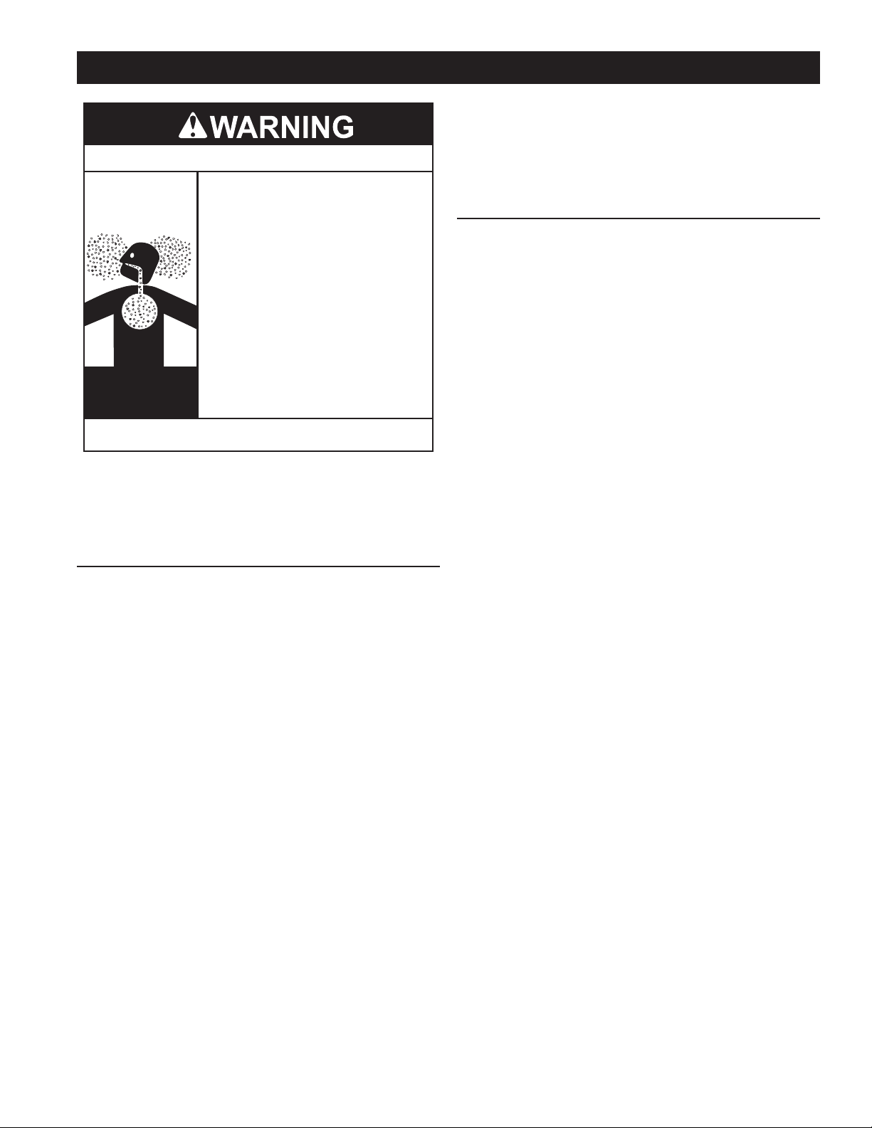
VENTING INSTALLATION
Breathing Hazard - Carbon Monoxide Gas
Install vent system in accordance with codes.
•
Do not operate water heater if exposed to flooding or
•
water damage
Special consideration must be taken with installations
•
above 10,000 feet (3,048 m) refer to high altitude
section of this manual.
Do not operate if soot buildup.
•
Do not obstruct water heater air intake with insulating
•
jacket or blanket.
Do not place chemical vapor emitting products near
•
water heater.
Gas and carbon monoxide detectors are available.
•
Never operate the heater unless it is vented to the
•
outdoors and has adequate air supply to avoid risks
of improper operation, fire, explosion or asphyxiation.
Analyze the entire vent system to make sure that
•
condensate will not become trapped in a section of
vent pipe and therefore reduce the open cross
sectional area of the vent.
Breathing carbon monoxide can cause brain damage or death.
Always read and understand the instruction manual.
Never operate the water heater unless it is vented to the outdoors.
The instructions in this section of the manual must be followed
to avoid choked combustion or recirculation of ue gases. Such
conditions cause sooting of the combustion chamber, burners
and ue tubes and creates a risk of asphyxiation.
GENERAL VENTING INFORMATION
The water heaters covered in this manual are operationally
equivalent to Category IV appliances and may be installed in
either a Power Vent or Direct Vent conguration.
APPROVED MATERIALS
Approved vent and intake air pipe materials that may be used in
the United States:
• PVC Schedule 40 (ASTM D 2241 / CSA B181.2, ASTM D
1785 / CSA B137.3
• CPVC Schedule 40 (ASTM F-411 / CSA B137.6)
• Polypropylene
• AL29-4C Stainless Steel
Approved vent and intake air pipe materials that must be used
in Canada:
• ULC S636 PVC / CPVC
• ULC S636 Polypropylene
• AL29-4C Stainless Steel
CATEGORY IV APPLIANCE
Category IV appliances operate with a positive vent (exhaust)
static pressure and with vent gas temperatures low enough to
produce condensate in the vent piping.
POWER VENT CONFIGURATION
Power Vent congurations derive all combustion air from the
room where they are installed and discharge all ue gases to
the outdoor atmosphere through a sealed vent (exhaust) pipe.
Power vent congurations have one vent pipe connected to the
water heater which can be terminated in a vertical or horizontal
arrangement. See Figure 42 and Figure 43 on page 35.
DIRECT VENT CONFIGURATION
Direct Vent congurations derive all combustion air directly from
the outdoor atmosphere through a sealed intake air pipe and
discharge all ue gases to the outdoor atmosphere through a
sealed vent (exhaust) pipe. Direct Vent congurations have two
pipes connected to the water heater, one vent pipe and one
intake air pipe. Direct Vent congurations can be terminated in
one of seven different arrangements. See Figure 44 on page
35 through Figure 50 on page 36.
GENERAL VENTING INSTRUCTIONS
These instructions must be followed on all installations.
1. DO NOT install the water heater in a Power Vent conguration
unless there is adequate supply of fresh air, see Air
Requirements on page 17. If the installation space does
not provide an adequate supply of fresh air the water heater
must be installed in a Direct Vent conguration.
2. If the water heater is to be installed in a beauty shop,
barber shop, cleaning establishment, a laundry with dry
cleaning equipment or any space with contaminated air it is
imperative that the water heater(s) be installed in a Direct
Vent conguration so that all air for combustion is derived
from the outdoor atmosphere.
3. The vent and intake air piping must terminate outdoors.
4. The minimum clearance from combustible materials for the
vent (exhaust) and intake air piping shall be 0 inches. Vent
piping passing through a combustible wall or ceiling must be
a continuous run (no joints).
5. The water heater must be protected from freezing downdrafts
during shutdown periods.
6. The vent (exhaust) pipe must not be combined or connected
to any other appliance’s vent system or chimney.
7. The intake air pipe must not be combined or connected to
any other appliance’s intake air piping.
8. Locate the water heater where the vent (exhaust) and intake
air piping will remain within the maximum equivalent lengths
allowed. See Venting Requirements on page 22.
9. Do not install the vent or intake air piping in a manner that will
allow water to be trapped in the piping.
10. Vent pipes must be pitched a minimum of a 1/4 inch per foot
back to the water heater (to allow drainage of condensate).
11. Do not anchor the vent or intake air pipe directly to framed
walls, oors or ceilings unless rubber isolation pipe hangers
are used to prevent vibration noise from being transmitted.
12. Use only approved vent/intake air pipe sizes and materials.
See Venting Requirements on page 22.
13. Use only factory supplied vent and intake air or concentric
terminations. See the Venting Requirements on page 22.
14. Do not locate the vent (exhaust) or intake air terminations
where they would be objectionable due to noise at the
termination(s). This includes locations close to or across from
windows and doors.
15. Direct venting into dead air spaces such as alleys, atriums,
and inside corners can cause recirculation of ue gases.
Recirculation of ue gases will cause sooting, premature
failure of the heat exchanger and icing of the combustion
air intake during severe cold weather. To prevent the
recirculation of ue gases, maintain as much distance as
possible between the intake air and vent terminations.
16. Do not locate the vent termination over a public area where
condensate or vapor can cause a nuisance or ice hazard.
17. Ensure the screens in the factory supplied terminations are
securely installed to prevent blockage in the vent system.
21
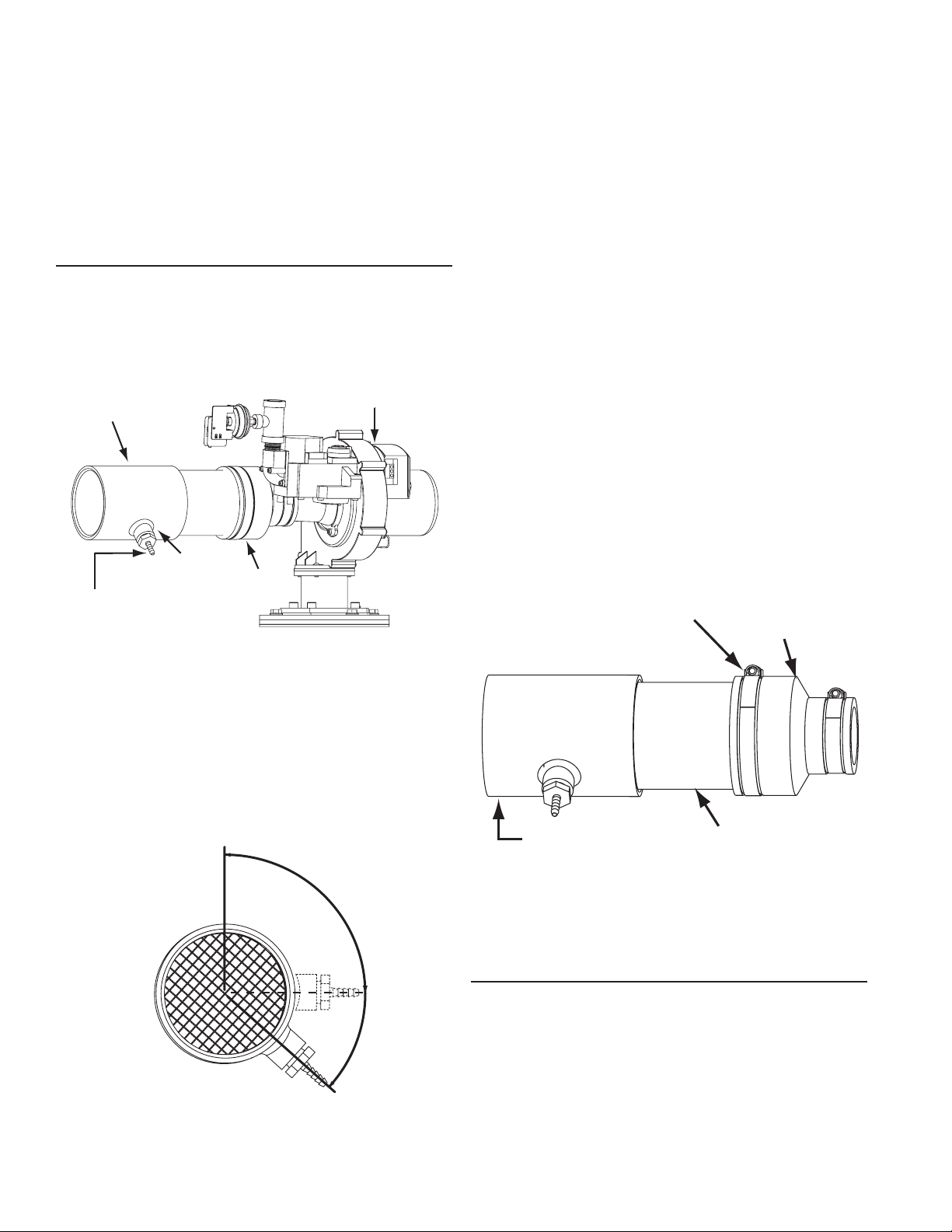
INTAKE AIR CONNECTION PIPE
18. Stress levels in pipe/ttings can be signicantly increased by
INTAKE AIR TEE FITTING
improper installation. If rigid pipe clamps are used to hold
the pipe in place, or if the pipe cannot move freely through a
wall penetration, the pipe may be stressed, or high thermal
stresses may be formed when the pipe heats up and expands.
Install accordingly to minimize such stresses.
19. Ensure the intake air connection Tee tting is oriented properly,
see page 22 for instructions.
20. Carefully read the Venting Requirements on page 22 and then
proceed to the Venting Installation Sequence on page 23.
INTAKE AIR CONNECTION
The water heaters covered in this manual are factory equipped
with a unique Combustion Blower and intake air connection
Tee tting. The Tee is a 3" x 3" x 1/2" fitting. The intake air
connection Tee tting has a hose barb installed in the 1/2 inch
branch to connect the Blocked Intake Air switch sensing tube,
see Figure 14.
FACTORY INSTALLED
INTAKE AIR TEE FITTING
1/2 INCH
BRANCH
HOSE BARB FITTING FOR
BLOCKED INTAKE AIR
SWITCH SENSING TUBE
COMBUSTION BLOWER ASSEMBLY
FERNCO
COUPLING
Figure 14
COMBUSTION BLOWER
The intake air Tee tting is factory installed with the 1/2 inch
branch and hose barb angled to the right at approximately 130°
when viewed from the end, see Figure 15. The Tee tting's
1/2 inch branch and hose barb must not be angled any lower
(towards the ground) than this factory specication. Angling
higher, up to a 90° position, will not adversely affect operation
and is acceptable.
INSPECT/ADJUST INTAKE AIR TEE FITTING
Inspect the angle of the Tee tting's 1/2 inch branch and hose
barb while viewing from the end of the Tee, see Figure 16. If the
angle of the Tee tting 1/2 inch branch and hose barb is lower
than shown, adjustment will be necessary. To adjust the intake
air Tee tting angle follow the steps listed below.
Adjustment Procedure:
21. Ensure the water heater is turned off at the on/off switch on
the front of the water heater.
22. Disconnect the Blocked Intake Air switch sensing tube, see
Figure 3 on page 8 for location.
23. Loosen the large hose clamp on the Fernco coupling that
connects the intake air connection pipe to the Combustion
blower, see Figure 16.
24. Adjust the angle of the Tee tting so that the 1/2 inch branch
and hose barb are at the proper angle as shown in Figure 15.
25. Retighten the large hose clamp on the Combustion Blower
intake air Fernco coupling,
26. Reconnect the Blocked Intake Air switch sensing tube making
sure the sensing tube is securely connected at both ends and
is not kinked.
LARGE HOSE
CLAMP
FERNCO
COUPLING
Ensure the hose barb installed in the Tee tting IS NOT facing
down towards the ground (180° - 6 o'clock position) before venting
installation begins. The barb tting must be angled between 90°
and no more than 130° as shown in Figure 15. If the barb tting
is facing down, residual condensate that occasionally forms in
the intake air pipe can drain into the Blocked Intake Air switch
through the attached sensing tube and damage the switch. This
condition can also lead to Blocked Intake Air fault conditions and
associated control system lock outs.
90° TO 130°
END VIEW
CORRECT ORIENTATION
Figure 15
INTAKE AIR
3 INCH PVC
TEE FITTING
Figure 16
VENTING REQUIREMENTS
FIELD SUPPLIED FITTINGS
Field supplied ttings should be equivalent to the piping material
being installed. Field installed/supplied ttings will add equivalent
feet to the vent or intake air piping as indicated below. All eld
supplied/installed ttings and piping must be factored into the
equivalent feet calculations.
• 90° elbows (short or long radius) are equivalent to 5 linear
feet (152 cm) of pipe.
• 45° elbows (short or long radius) are equivalent to 2.5 linear
feet (76 cm) of pipe.
22
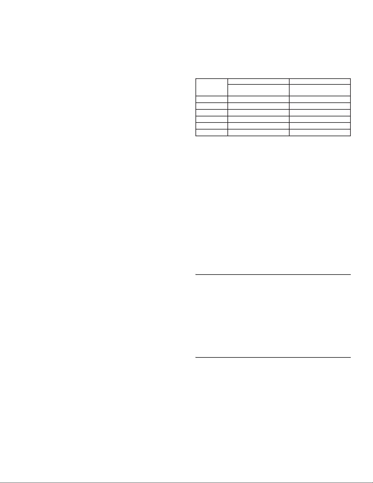
NOTE: Refer to Tables 9 and 10 on page 29 for the equivalent
linear pipe length of AL29-4C® 45° and 90° elbows.
PRIMER AND CEMENT
Tetrahydrofuran (THF) primer should be used to prepare the surfaces
of pipe and ttings for solvent welding. If CPVC or ABS
pipe and
ttings are used, then the proper cement must be used for all joints,
including joining the pipe to the factory provided terminations (PVC
material). PVC Materials should use ASTM D-2564 Grade Cement;
CPVC Materials should use ASTM F-493
Grade Cement and ABS
Materials should use ASTM D-2235 Grade Cement.
PIPE SIZE REQUIREMENTS
The water heaters covered in this manual are certied for the use
of 3 and 4 inch pipe for the vent (exhaust) and intake air piping.
If the installed equivalent length for the intake air or vent piping
will be 50 feet (15.2 m) or less, 3 inch pipe must be used. If the
installed equivalent length will be more than 50 feet (15.2 m), 4
inch pipe must be used.
NOTE: Install the pipe size required for the installed equivalent
length of each pipe independently. IE: If the intake air pipe will be
50 equivalent feet or less and the vent pipe will be more than 50
equivalent feet; the intake air pipe must be installed using 3 inch
pipe and the vent must be installed using 4 inch pipe.
MAXIMUM EQUIVALENT LENGTHS
Three Inch Pipe
The water heaters covered in this manual are certied to
a maximum length of 3 inch pipe for the exhaust venting
arrangement of 50 equivalent feet (15.2 m). The certied
maximum length of 3 inch pipe for intake air piping is also 50
equivalent feet (15.2 m). IE: On Direct Vent installations both
pipes can be up to 50 equivalent feet (15.2 m).
Four Inch Pipe
The water heaters covered in this manual are certied to
a maximum length of 4 inch pipe for the exhaust venting
arrangement of 120 equivalent feet (36.5 m). The certied
maximum length of 4 inch pipe for intake air piping is also 120
equivalent feet (36.5 m). IE: On Direct Vent installations both
pipes can be up to 120 equivalent feet (36.5 m).
MINIMUM EQUIVALENT LENGTHS
Three Inch Pipe
The water heaters covered in this manual are certied to a
minimum length of 3 inch pipe for the vent (exhaust) of 7
equivalent feet (2.1 m). There is no minimum equivalent feet
requirement for the intake air pipe.
Four Inch Pipe
The water heaters covered in this manual are certied to
a minimum length of 4 inch pipe for the vent (exhaust) of 50
equivalent feet (15.2 m). There is no minimum equivalent feet
requirement for the intake air pipe.
MAXIMUM NUMBER OF ELBOWS
Three Inch Pipe
The vent pipe may have a maximum of four 90° elbows installed
when 3 inch pipe is being used. The intake air pipe may also
have a maximum of four 90° elbows installed. IE: in a Direct Vent
conguration each pipe can have up to four 90° elbows installed.
NOTE: Refer to Tables 9 and 10 on page 29 for the equivalent
linear pipe length of AL29-4C® 45° and 90° elbows.
Four Inch Pipe
The vent pipe may have a maximum of six 90° elbows installed
when 4 inch pipe is being used. The intake air pipe may also
have a maximum of six 90° elbows installed. IE: in a Direct Vent
conguration each pipe can have up to six 90° elbows installed.
FACTORY SUPPLIED FITTINGS
The water heater ships with two (2) factory supplied 3 inch
terminations (PVC 45° elbows with debris screen). Factory supplied
vent and intake air terminations, concentric, or low prole terminations
must be used. Factory supplied terminations and installed ttings
(exhaust/condensate elbow and intake air connection) add zero
equivalent feet to the vent and intake air piping.
TABLE 6
Number of
90° Elbows
Installed
One (1) 45 feet (13.7 meters) 115 feet (35.0 meters)
Two (2) 40 feet (12.2 meters) 110 feet (33.5 meters)
Three (3) 35 feet (10.7 meters) 105 feet (32.0 meters)
Four (4) 30 feet (9.1 meters) 100 feet (30.5 meters)
Five (5) N/A 95 feet (29.0 meters)
Six (6) N/A 90 feet (27.4 meters)
3 Inch Pipe 4 Inch Pipe
Maximum Feet (Meters) Maximum Feet (Meters)
4 INCH EXTENDED VENT TERMINATIONS
When 4 inch intake air or vent pipe is installed, factory supplied 4
inch terminations must be used. Contact your local distributor or
call the parts department (phone number listed on the back cover
of this manual) to order 4 inch termination(s).
OPTIONAL CONCENTRIC & LOW PROFILE TERMINATIONS
The water heaters covered by this manual may be installed in a
Direct Vent conguration using a 4 inch concentric termination or
a 3" or 4" low prole termination.
Concentric and Low Prole terminations must be ordered
separately. Contact your local distributor or call the parts
department phone number listed on the back cover of this
manual to order.
Concentric & Low Prole Vent Termination Part Numbers:
• 4" Concentric Termination # 9006328005
• 3" Low Prole Termination # 9008933005
• 4" Low Prole Termination # 9008934005
VENTING INSTALLATION SEQUENCE
1. Read General Venting Instructions on page 21 and Venting
Requirements on page 22 before proceeding. These instructions
and requirements must be followed on all installations.
2. Determine whether the water heater will be installed in
a Power Vent or Direct Vent conguration and which vent
system arrangement will be used for the installation. See the
various venting arrangements on pages 35 and 36.
3. Proceed to the applicable instructions:
• Power Vent Installation on page 23.
• Direct Vent Installation on page 24.
POWER VENT INSTALLATION
1. Read the General Venting Instructions on page 21 and
Venting Requirements on page 22 before proceeding.
These instructions and requirements must be followed in
addition to the instructions below that are specic for Power
Vent congurations.
2. Determine which Power Vent arrangement will be used for
the installation; vertical or horizontal termination. See Figure
42 and Figure 43 on page 35.
3. Determine the vent pipe size for the installation, see Venting
Requirements on page 22.
4. Plan the layout of the vent piping backwards from the
termination point outdoors to the water heater. Layout the
vent piping to use a minimum of pipe and elbows.
5. Install the termination rst.
23

If the vent piping will terminate vertically, through a roof, see
Vertical Termination Installation on page 25.
If the vent piping will terminate horizontally, through a
sidewall, see Sidewall Termination Installation on page 27.
6. When installation of the termination is complete install
necessary piping and ttings to route the vent piping back to
the water heater.
7. The vent pipe must be supported properly to avoid bending
or failure. The water heater manufacturer recommends that
the vent pipe be supported every 5 feet (152 cm) of vertical
run and every 3 feet (91 cm) of horizontal run.
8. Do not install the vent piping in a manner that will allow water
to be trapped in the piping.
4” PIPE FIELD
SUPPLIED
4” x 3” REDUCER
FIELD SUPPLIED
3” PIPE FIELD
SUPPLIED
EXHAUST ELBOW
VENT CONNECTION
FACTORY INSTALLED
VENT (EXHAUST) CONNECTION
Figure 17
9. All vent (exhaust) pipes must be pitched a minimum of a
1/4 inch per foot back to the water heater (to allow drainage
of condensate).
10. If installing 3 inch vent pipe connect the vent pipe to the
exhaust elbow on the water heater.
11. If installing 4 inch pipe transition to 3 inch pipe at the exhaust
elbow on the water heater as shown in Figure 17. The eld
installed 3” pipe between the exhaust elbow and the 4” x 3”
reducer coupling should be 18 inches (45 cm) or less in length.
DIRECT VENT INSTALLATION
1. Read the General Venting Instructions on page 21 and
Venting Requirements on page 22 before proceeding.
These instructions and requirements must be followed in
addition to the instructions below that are specic for Direct
Vent congurations.
2. Determine which Direct Vent arrangement will be used for
the installation. There are seven (7) Direct Vent arrangement
options. See Figures 44 through 50.
3. Determine vent and intake air pipe size to be used for the
installation; see Venting Requirements on page 22.
4. Plan the layout of the vent and intake air piping backwards
from the termination point outdoors to the water heater.
Layout the vent and intake air piping to use a minimum of
pipe and elbows.
5. Install the terminations rst.
If standard terminations are being used and the intake air
or vent piping will terminate vertically, through a roof, see
Vertical Termination Installation on page 25.
If standard terminations are being used and the intake air or
vent piping will terminate horizontally, through a sidewall, see
Sidewall Termination Installation on page 27.
If a concentric termination(s) will be used see Concentric
Termination Installation on page 30.
If a low-prole termination will be used see Low Prole
Termination Installation on page 34.
6. When installation of the termination(s) is complete Install
necessary piping and ttings to route the intake air and vent
piping back to the water heater.
7. The intake air and vent piping must be supported properly
to avoid bending or failure. The water heater manufacturer
recommends that the vent and intake air piping be supported
every 5 feet (152 cm) of vertical run and every 3 feet (91 cm)
of horizontal run.
8. Do not install the vent or intake air piping in a manner that will
allow water to be trapped in the piping.
9. A eld supplied condensate Tee tting and drain hose
should be installed in the intake air piping near the water
heater in colder climates with heavy snow accumulations
and in areas that regularly experience high humidity. The
drain hose should be routed to an adequate oor drain
separate from any other condensate drains. See Figure 20
on page 25.
NOTE: Snow being pulled into the intake air piping and
then melting can lead to excessive amounts of water
accumulation and damage water heater components. Warm,
humid outdoor air can lead to excessive condensation
inside the intake air piping and may also damage water
heater components.
10. The intake air and vent (exhaust) piping must be pitched a
minimum of a 1/4 inch per foot back to the water heater (to
allow drainage of condensate).
11. If installing 3 inch vent pipe connect the vent pipe to the
exhaust elbow on the water heater.
12. If installing 4 inch vent pipe transition to 3 inch pipe at the
exhaust elbow on the water heater as shown in Figure 17 on
page 24. The eld installed 3” pipe between the exhaust
elbow and the 4” x 3” reducer coupling should be 18 inches
(45 cm) or less in length.
13. Ensure the Intake Air Screen on the Intake Air Connection to
the water heater is removed before connecting the intake air
pipe to the water heater. See Figure 18.
Breathing Hazard - Carbon Monoxide Gas
Do not obstruct water heater air intake.
Gas and carbon monoxide detectors
are available.
Install water heater in accordance with
the instruction manual.
Breathing carbon monoxide can cause brain damage or
death. Always read and understand instruction manual.
NOTE: Do not leave the screen inside the Intake Air
Connection for Direct Vent installations. Once the intake
air pipe is installed the screen will be hidden from view and
may become clogged with debris over time. This will cause
improper combustion and may also lead to Blocked Intake
Air fault conditions and associated control system lock outs.
24
 Loading...