

Page 1
®
FFT spectrum display unit
SDU5600
PROFESSIONAL SPECTRUM
DISPLAY UNIT FOR USE WITH
A COMPANION RADIO
OPERATING MANUAL
1
Page 2

2
Page 3

Index
Index
Safety notices ................................................................................................. 5
SDU5600 brief circuit description .................................................................... 6
LCD resolution ................................................................................................ 6
Block diagram ................................................................................................. 7
Introduction ..................................................................................................... 8
1 Controls and Descriptions ......................................................................... 9
1.1 Front panel ................................................................................................ 9
1.2 Rear panel ................................................................................................ 10
2 Connection ................................................................................................. 11
2.1 Connection with the power supply ............................................................. 11
2.2 Connection with the receiver ..................................................................... 11
3 Preparations ............................................................................................... 12
3.1 Configuration of the receiver ..................................................................... 12
3.2 Start-up ..................................................................................................... 12
4 Basics ......................................................................................................... 13
4.1 Control ...................................................................................................... 13
4.2 Display ...................................................................................................... 14
4.3 Main key layout ......................................................................................... 15
4.4 Clear (CLR) key ........................................................................................ 16
4.5 Default mode and clear mode ................................................................... 16
4.6 When the communication with the companion receiver has failed ............. 16
5 Configuration of the SDU5600 ................................................................... 17
5.1.1 Configuration (CONF) ............................................................................. 17
5.1.2 Applicable receivers ............................................................................... 18
5.2.1 Configuration of the receiver .................................................................. 19
5.2.2 Selecting the receive frequency .............................................................. 20
5.3 Setup of the monitoring mode ................................................................... 22
5.4 Basic setup for each monitoring mode ...................................................... 23
5.4.1 Spectrum analysers mode ...................................................................... 23
5.4.2 Step resolution mode ............................................................................. 24
5.4.3 Channel scope mode ............................................................................. 25
5.4.4 Common features shared by different monitoring ................................... 26
3
Page 4

Index
5.5 Marker ...................................................................................................... 28
5.6 Calculation facility ..................................................................................... 30
5.7 Waterfall display facility ............................................................................. 31
5.8 On/off of the display information ............................................................... 32
5.9 Beep alert ................................................................................................. 32
5.10 Factory default/reset ............................................................................... 32
6 Operating the SDU5600 ............................................................................. 33
6.1 Operate the SDU5600 with the AR5000A+3 .............................................. 33
6.2 Monitor the VHF FM band in the spectrum analyser mode ........................ 34
6.3 Monitor the FM broadcast band in the step resolution mode ..................... 35
6.4 Monitor the VHF air band in the channel scope mode ............................... 36
6.5 Suitable applications of each monitoring mode ......................................... 37
7 Useful information ..................................................................................... 38
8 SDU5600 Computer control ....................................................................... 39
8.1 Communication parameters and connecting lead ...................................... 39
8.2 Delimiter ................................................................................................... 39
8.3 Basic format of the command ................................................................... 40
8.4 RS232 command list ................................................................................ 40
Spectrum analysis ............................................................................... 41
Visual command .................................................................................. 43
User interface ...................................................................................... 44
General information ............................................................................. 46
Notes for programmers ........................................................................ 48
9 Specification .............................................................................................. 49
4
Page 5

Safety notices
Every effort has been made to make this manual correct and up to date. Due to continuous
development of the product and by error or omission, anomalies may be found and this is
acknowledged.
© This manual is protected by copyright AOR Ltd 2003. No information contained in this manual may
be copied or transferred by any means without the prior written consent of AOR Ltd. AOR and the ‘AOR
logo’ are trade marks of AOR Ltd. All other trade marks and names are acknowledged.
& Level of risk
As there SDU5600 is powered from 12V DC, there is little chance of serious injury as long as common
sense is applied.
Observe the polarity of connections if the supplied AC power unit is not being used. DC input is a
nominal 12V DC wired centre positive. Reverse polarity connection will damage the SDU5600 and
potentially could lead to the risk of fire or explosion under severe circumstances.
Carefully handle the AC plug of the supplied AC power unit to prevent touching the terminals when
inserting or removing from the AC socket. NEVER connect the SDU5600 directly to the AC supply.
SAFETY NOTICE - Always disconnect the power supply from the AC socket when not in use.
Explanation of risk warning mark
Whenever the book symbol & is used in this operating manual, an important point is being made which
may relate to risk of personal injury or damage to the unit if ignored.
When the pointing finger is used, the associated text provides useful operational information of
special note (such as a tip). No risk or personal injury or damage is associated.
Handling the SDU5600
Use a soft, dry cloth to gently wipe the SDU5600 clean, never use abrasive cleaners or organic solvents
which may damage certain parts. Treat the unit with care, avoid spillage or leakage of liquids into the
cabinet and power supply. Special care should be taken to avoid liquid entering around the keys, main
dial or via the connection sockets.
Never push or knock the TFT LCD display screen which is very
fragile and sensitive to shock.
Special remarks
Do not use or leave the SDU5600 in direct sunlight (especially the TFT display). It is best to avoid
locations where excessive heat, humidity, dust and vibration are expected. Always keep the SDU5600
free from dust and moisture.
AC adaptor (power unit)
The SDU5600 may be provided with either a suitable AC / DC power unit. The SDU5600 is designed for
operation from a nominal 12V DC regulated power supply (12 to 14V is acceptable), which should be
capable of supplying a minimum of 1A continuous, ideally a 2A unit should be employed.
& Note: Never connect the SDU5600 directly to an AC supply.
The DC input socket uses a mini power connector (subject to EIAJ RC-5320A) and is wired centre
positive (+), the chassis of the unit is at negative ground. To minimise the potential for power cable
interference, it is suggested that a ferrite clamp be fitted to the connecting cable.
Other warnings
There are no internal operator adjustments. In the unlikely event of servicing being required, please
contact your dealer for technical assistance.
Should the SDU5600 appear to behave strangely, normal operation may easily be regained by resetting
the microprocessor. Simply power down the SDU5600 and disconnect the power supply... leave for 30
seconds then reconnect and power-up again.
It is possible to RESET the microprocessor, please refer to section 5-10, page 32 for further information.
If used with the AR3000A, a small modification is required to the receiver in order to provide the required
10.7 MHz IF output. If using the ICOM IC-R7100, the optional ICOM CT17 (RS232/CIV) interface is
required.
E&OE
5
Page 6

Circuit description
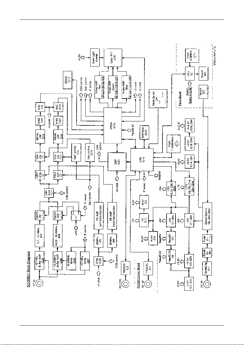
SDU5600 Brief circuit description
The RF signal is fed by BNC socket into the SDU at a selected frequency of either 10.7MHz or 45.05MHz depending on the radio IF
frequency being used. This signal is split into two different signal paths depending upon which input frequency is selected. Both paths
are buffered and have Band Pass Filters with a bandwidth of +/-5kHz to eliminate unwanted signals outside of this range.
After the BPF, both signal paths join and are amplified by a single LNA (Low Noise Amplifier). The output signal feeds a pair of Dual
Balanced Mixers.
Here the input RF signal is mixed with two orthogonal sinusoidal signals produced by the DDS (Direct Digital Synthesis) section to
give two resultant signals at audio frequencies (one used as real, one as imaginary). The gain of both signal paths is also controlled at
this point.
The audio level signals are fed through 80kHz LPFs (Low Pass Filters) and finally converted from Analogue into Digital signals before
being fed to the FPGA (Field Programmable Gate Array).
The digital signal is now processed by the DSP (Digital Signal Processor) to give an RGB Video output via the FPGA which drives a
colour TFT LCD display.
The DSP is controlled by the main CPU and its EEPROM memory. The front panel keypad switches and rotary encoder are fed to the
main CPU via a separate slave microprocessor on the front panel.
RS232 control and Receiver control ports connect (indirectly) to the main CPU.
A comprehensive power supply section has been used in the unit to give the required supply levels of 2.5v, 3.3v, 5v, 6v, 9.5v, 17v, -5v,
-7v and -15v. The input is protected for reverse current & unwanted RF and is internally fused.
LCD resolution
The LCD provides high resolution of 320 horizontal dots from the left to right edges of screen. As a result, there are about 40 steps
per graticule division with eight divisions making up the total width. The minimum displayed bandwidth is 160kHz and the maximum
displayed width is 10000 kHz (10 MHz) representing ± 5 MHz.
To calculate the LCD-step, divide the SPAN bandwidth in kHz by 320. Examples are as follows:
10000 kHz (10 MHz) 32.250 kHz
5000 kHz (5 MHz) 15.625 kHz
2000 kHz (2 MHz) 6.250 kHz
1000 kHz (1 MHz) 3.250 kHz
160 kHz (0.16 MHz) 0.500 kHz
It is possible to force the LCD-step to equal the receive tuning step using a similar process. Multiply the receive tuning step size in
kHz by 320 (dots) to obtain the required total span width in kHz.
For example, for a 5 kHz tuning and LCD step, 5 x 320 = 1600 kHz span
The following table presents commonly used step sizes:
0.5 kHz (minimum step size) 160 kHz (0.160 MHz)
5 kHz 1600 kHz (1.600 MHz)
6.25 kHz 2000 kHz (2.00 MHz)
9 kHz 2880 kHz (2.880 MHz)
10 kHz 3200 kHz (3.200 MHz)
12.5 kHz 4000 kHz (4.000 MHz)
20 kHz 6400 kHz (6.400 MHz)
25 kHz 8000 kHz (8.000 MHz)
31.25 kHz represents maximum span of 10000 kHz (10 MHz)
6
Page 7
Block diagram
7
Page 8

Introduction & preparation
Introduction
Thank you for purchasing the SDU5600 FFT spectrum display unit. AOR was the
first company in the world to market a colour spectrum display unit (SDU5000) for
professionals and the top-end of hobbyist listeners. The SDU5500 followed adding
sophistication and the SDU5600 is truly a successor incorporating a high resolution
5 inch (127mm) colour TFT display featuring FFT signal analysis and built-in waterfall
display backed by the latest microprocessor technology to ensure high versatility and
reliability. To get the best possible results, we recommended that you read this manual
to fully familiarise yourself with the SDU5600.
Major features
The SDU5600 has been designed to be a highly effective spectrum monitor unit which
is capable of digitally processing the IF frequency taken from a communications
receiver through the use of FFT for professional quality spectrum analysis. The 5 inch
TFT colour LCD screen is used to achieve the finest possible resolution.
The SDU5600 has been primarily designed to complement to the AOR AR5000 series
of receivers in terms of operational features and cosmetic design. Also other types of
receiver such as the AOR AR-ONE, AR3000A and AR8600MK2 and ICOM ICR8500 +
ICR7100 can be used (modification and additional hardware required).
A wide variety of monitoring modes are available with the convenience of operators in
mind which include Step Resolution Mode for general monitoring or Channel Scope
Mode for monitoring the channelised signals. It also incorporates a Waterfall facility
(as commercial grade spectrum analysers do), to display the changing conditions of
signal spectrum with varying colours in a form of waterfall.
Following the success of its predecessors, SDU5000 and SDU5500, the new
SDU5600 provides the same AV, Peak Hold and Peak value readings which are
downloadable to the PC via a communications port. The SDU5600 can be remote
controlled through the use of the communications port to further expand the range of
applications for spectrum monitoring.
Supplied accessories
1 x SDU5600 main unit
1 x BNC RF patch lead for IF connection
1 x DB9 patch lead for serial communications - male to male
1 x Handbook
1 x AC power supply
8
Page 9
Section 1, 1-1
1 Controls and Descriptions
Control and display of the SDU5600 is via the front panel with the rear panel
providing connections for the companion receiver, power and computer.
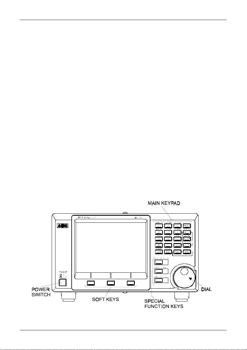
1-1 Front panel
LCD: The large high resolution 5 inch colour TFT display provides all operational information and
spectrum display. The background is black with green graticule and white lettering for critical
information. Menu items are varying shades of blue, the valid indicator is green with the function
indicator in ‘reverse lettering’ yellow. The marker line is white and changes to purple when exactly
positioned over a graticule line. The colours cannot be changed.
Power switch: Press once to latch the switch in, switching on the SDU5600. T o switch off the
SDU5600, press the switch a second time, the switch latches outward. When switched on, the LCD
briefly displays the model and firmware numbers.
Tilt bail bar: A tilt bail bar is provided under the front panel (on the bottom case half) so that the
SDU5600 may be tilted upward at the front to improve visibility in certain installations.
Soft function keys: Each one of these three ‘soft keys’ has multiple roles as indicated on the LCD
screen depending on the circumstances in operation.
Special function keys: These three keys positioned to the left of the DIAL are to be used solely for
specific purposes such as to enter a centre frequency, frequency span, display increment and input
sensitivity.
Dial: The DIAL is a rotary control and is used to move the cursor, to make a selection or to move the
marker/centre frequency.
Main keypad: Used to enter numeric information, to control the companion receiver, etc. When a
valid key press is sounded, the SDU5600 will provide a high pitch ‘beep’ (happy), if an invalid key
press is made, a low pitched ‘beep’ (sad) is sounded. The beep can be toggled on/off using the key
sequence FUNC + 6 (BEEP), the default is on.
9
Page 10
Section 1-2
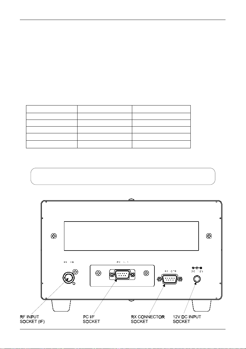
1-2 Rear panel
RF Input socket: The IF output (10.7 MHz / 45.05 MHz) from a suitable receiver such as the
AR5000A should be connected to this BNC input socket using a 50 OHM patch lead constructed of
quality coaxial cable such as RG58/U, UR43, UR76 etc. A suitable BNC-BNC lead is supplied.
PC I/F socket (male): A controlling computer may be connected to this 9-pin D-type male socket.
Ensure this socket is only commented to a computer for hands-off operation, although it is very
unlikely that incorrect connection to a computer or similar device would cause damage.
RX connection socket (female): The supplied 9-way to 9-way ‘D-type’ male to male lead is used to
connect the SDU5600 to the AR5000A receiver. If used with another receiver , a suitable serialadapter or connecting cable will be required. Wiring should be as follows:
SDU5600 9-pin male 9-pin male (AR5000A) 25-pin male (AR3000A)
223
332
5 5 7 GND
774
885
12V DC input socket: The supplied power unit is terminated with a centre positive (+) polarity.
The plug specification follows EIAJ RC-5320A (Class-4).
There are four screw holes (unused), two on each side of the cabinet.
They are a provision for rack mount application. Size of the screw is M4x8.
10
Page 11
Section 2, 2-1, 2-2
2 Connection
2-1 Connection with the power supply
Where possible, use the supplied AC/DC power unit. Make sure the main switch of the SDU5600 is
in the OFF position before connecting the power supply.
2-2 Connection with the receiver
This hand book is compiled mainly referring to the AR5000A series receiver as the principal
companion receiver. Any reference to other types of receiver will be made separately when and
where necessary.
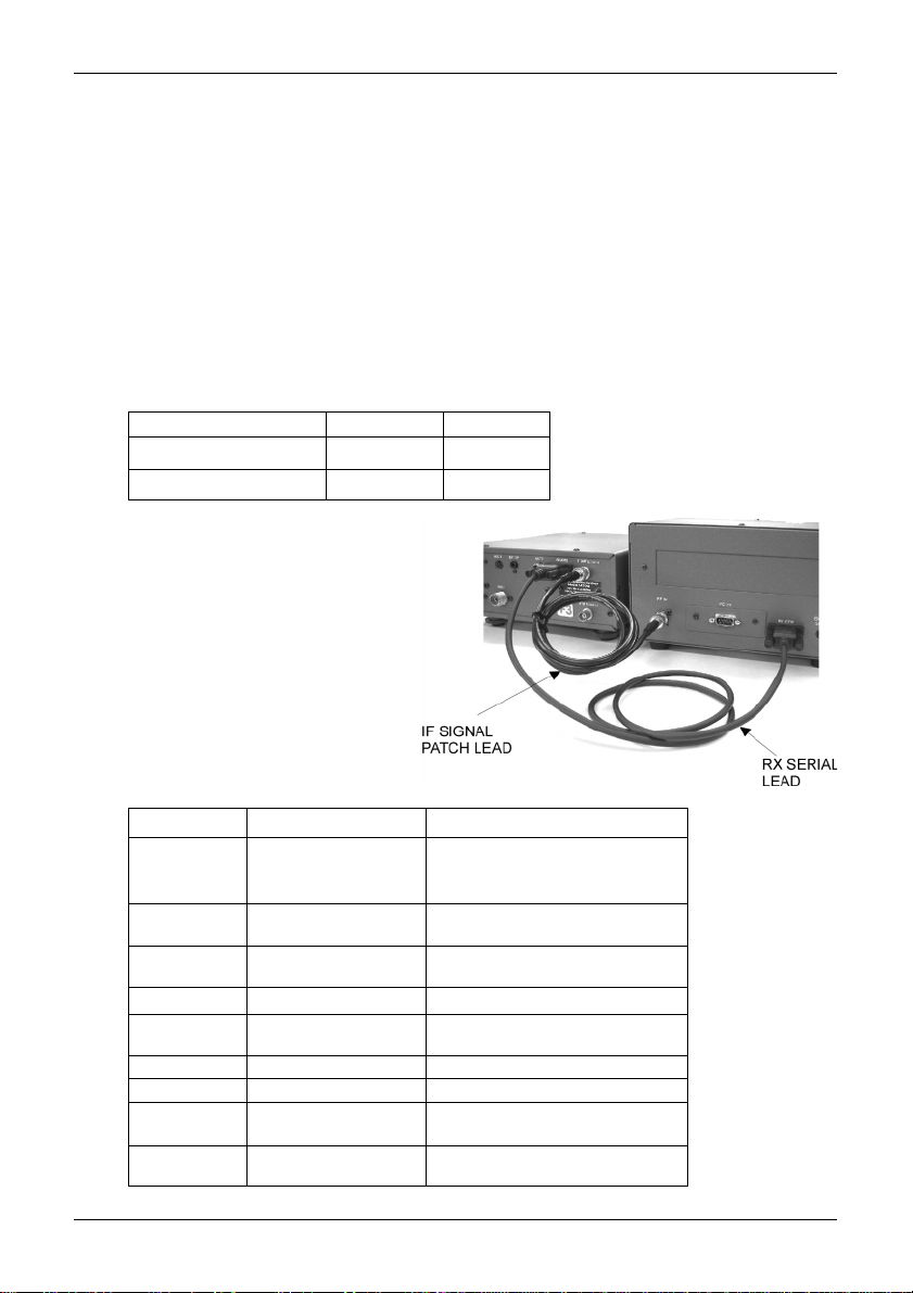
Make sure that both the SDU5600 and AR5000A are switched off. Perform the connection of the
both units referring to the photo shown here, using the IF signal connection patch lead and RX serial
connection lead. The following table shows the correct connection of each plug & socket.
AR5000A SDU5600
IF signal patch lead IF OUT RF IN
RX serial lead REMOTE RX CTR
If you wish to use a receiver other than the AR5000A
proceed to connect the 10.7MHz IF output from the
receiver to the RF IN BNC socket on the rear of the
SDU5600... the AR3000A will require a modification in order to provide a suitable signal. Connect
the RS232 data lead from the receiver to the RX
CTR socket of the SDU5600, the companion
receiver ‘thinks’ it is communicating with a
computer, but is actually communicating
with the SDU5600 (the ICOM ICR7100
requires the optional ICOM CT17
CIV/RS232 interface).
RX Menu Applicable receiver Requirements
AR5000 AR5000A+3 Configure the IF output
AR3000A AR3000A Modifications to the IF output circuit
AR8600 (10M) AR8600MK2 Modifications to the output circuits
AR8600 (45M) AR8600MK2 Modification of TV converter
AR8200 AR8200MK2 Modification of TV converter and
AR-ONE AR-ONE Configure the IF output
RFU5600 RFU5600
IC-R8500 IC-R8500 Use of batch lead with RCA/PHONO plug
IC-R7100 IC-R7100 Use of batch lead with RCA/PHONO plug
AR5000A
AR5000+3
AR5000
(AR3000 not applicable)
on all modes other than WFM
AR8200MK3 use of 8200PC interface
Configure the IF output
Use of CT-17 interface
and other requirements.
the RX selection menu, applicable receivers
The table here indicates the type of receiver in
you wish to operate with the SDU5600.
whereby you can select other receivers which
The SDU5600 offers a RX selection menu
11
Page 12
Section 3, 3-1, 3-2
3 Preparations
3-1 Configuration of the receiver
The SDU5600 is primarily designed to operate with the receiver at 9600bps. The companion
receiver’s baud rate has to be configured to the same rate. Some type of receivers may require
additional modifications or interface, etc, which are explained as follows:-
AR5000 series: Configure the selection of external IF output and baud rate as per the following
table (refer to pages 29 & 30 sections 6-18 & 6-19 of AR5000 English language operating manual):
External IF output Select [EXT-IF 1]
RS232C Select 9600bps
After the configurations have been completed place
the receiver in VFO mode.
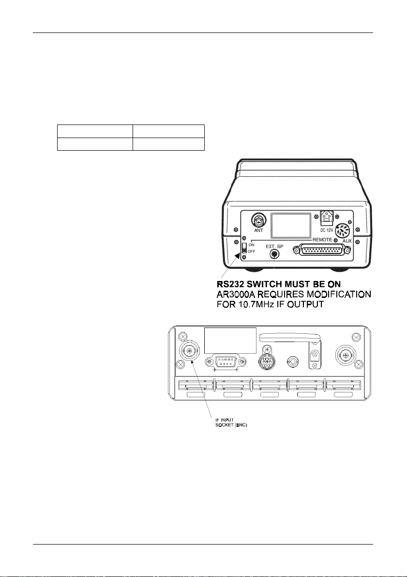
AR3000A: The AR3000A has to be modified by
AOR in order to produce a 10.7MHz IF output for
use with the SDU5600. The remote switch on the
rear panel has to be set to ON position, and baud
rate needs to be 4800bps (receiver’s default).
A screened RS232 connecting lead configured for
9-25 pin with male-pins at both ends must be used.
AR8200MK3: Configure the baud rate to 9600bps
by referring to pages 109 & 110 section 14-6 of the
AR8200 English language operating manual. Place
the receiver in VFO mode. For connection to the
SDU5600 the 8200PC interface lead is required
along with a gender changer. The AR8200MK3 has
to be modified by AOR to produce a 10.7MHz IF
output.
AR8600MK2: Configure the baud
rate to 9600bps by referring to page
108 section 14-5 of AR8600 English
language operating manual. Place
the receiver in VFO mode. For
connection to the SDU5600 the
supplied connecting leads have to be
used. T o enable IF output in ALL
MODES (rather than just WFM), refer
to page 18 for further information on
the modifications required.
3-2 Start-up
ALW AYS switch the receiver on before the SDU5600 and make any necessary adjustment of
communication speed and IF output (assuming the relevant modifications have been carried out and
connecting leads are in place as appropriate). Then switch on the SDU5600 by depressing the
POWER switch on the lower left of the front panel. The SDU5600 will power up, while the operating
system powers up you may notice horizontal lines on the LCD, this is normal. The SDU5600 will
briefly display the model number and firmware version called the ‘opening message’ before the
standard display. The SDU5600 is ready for operation.
12
Page 13
Section 4, 4-1
4 Basics
This section describes the front panel controls, detail of LCD display and introduces the method of
operation employed by the SDU5600 prior to further configurations and monitoring operations. It is
advisable that you read this section carefully before proceeding to explore the full capability of the
SDU5600.
4-1 Control
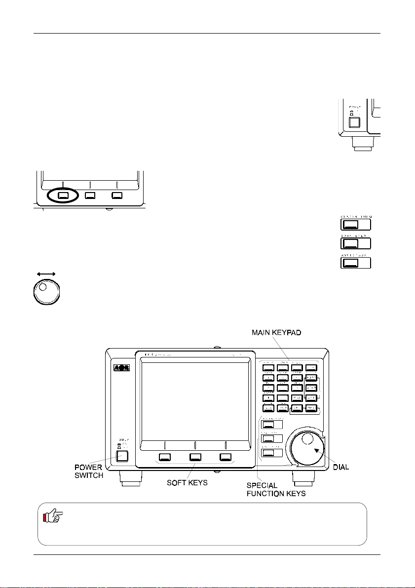
Power switch: Press once to latch the switch in, switching on the SDU5600. T o
switch off the SDU5600, press the switch a second time, the switch latches outward.
When switched on, the LCD briefly displays the model and firmware numbers.
Soft function keys: Each one of these three ‘soft keys’ has
multiple roles as indicated on the LCD screen depending on the
circumstances in operation. Throughout this manual, physical
keys and ‘soft keys’ are not differentiated when describing key
sequences.
Special function keys: These three keys positioned to the left of the DIAL are to be
used solely for specific purposes such as to enter a centre frequency, frequency span,
display increment and input sensitivity.
Dial: The DIAL is a rotary control and is used to move the cursor, to make a selection or to
move the marker/centre frequency.
Main keypad: Used to enter numeric information, to control the companion receiver, etc.
BACKUP
The SDU5600 is configurable in various ways to the requirements of the operator. All configuration data is
stored into FLASH ROM when the SDU5600 is switch off. However, in the event of failed connection /
communications with the companion receiver, a beep will be sounded and the SDU5600 will revert to the
factory default parameters.
13
Page 14
Section 4-2
4-2 Display
This section explains what you can expect to see on the SDU5600’s monitor screen
using Spectrum Mode as a typical example. The screen will appear differently when
switched to other operating modes.
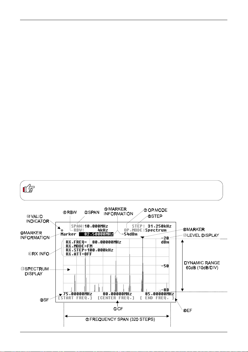
(1) Centre frequency - CF: The centre frequency reading is shown in MHz, providing
a minimum resolution of up to 10Hz.
(2) Frequency span - SPAN: The centre frequency appears in the middle of the display
with frequency extending to the left and right. The total frequency spread from the left
through centre to the right is referred to as the total SPAN and is indicated in MHz.
The maximum span is 10MHz and minimum is 0.160MHz (160kHz). The horizontal
scale is divided into 320 increments.
(3) Start frequency - SF: Displays the start frequency on the left of the graticule for
calibration purposes. Usually the start frequency is calculated based on the centre
frequency and bandwidth selected, but in certain menus can be directly programmed.
(4) End frequency - EF: Displays the end frequency on the right of the graticule for
calibration purposes. Usually the end frequency is calculated based on the centre
frequency and bandwidth selected, but in certain menus can be directly programmed.
(5) Resolution band width - RBW: The sampling filters may be selected from four
bandwidths of 4kHz, 32kHz, 64kHz and 128kHz. The smaller bandwidths will provide
greater detail of individual signals but wanted transmissions are easier to initially
identify using a wider filter.
Relationship between Frequency span and Frequency step
The LCD provides high resolution of 320 steps from the left to right edges of the screen (x-axis). A frequency bandwidth
represented by one step is calculated as STEP EQUALS SPAN DIVIDED BY 320, this being automatically done by the
SDU5600 in the Spectrum Mode. Refer to item (6) ‘Frequency step’ on page 15.
14
Page 15
Section 4-2, 4-3
(6) Step frequency - STEP: This value is displayed in kHz and indicates how wide one step
represents out of the 320 steps across the X-axis. The example of page 14 shows 31.250kHz as one
step which is obtained by taking the SPAN of 10MHz and dividing it by 320, the result is 31.250kHz since the X-axis is 10MHz wide in this example. In the Step resolution mode, it is possible to specify
the frequency bandwidth to be ‘one step’ rather than an often seemingly arbitrary value.
(7) Operation mode - OP .MODE: This legend indicates which one of three operating modes is
selected, there are three possibilities:
Spectrum Spectrum analyser mode
StepReso Step resolution mode
Channel Channel scope mode
(8) Marker + (9) Marker information: The marker (8) is a vertical line drawn on the LCD which can
be moved across the horizontal axis. The marker is capable of providing the instantaneous reading of
information where the marker is placed such as (9) frequency or signal strength of marker location.
In the marker menu, in addition to the instantaneous reading of marker information, the peak
search facility is provided. Any signals which are out of scale cannot be read. It is necessary to
adjust the gain for input signal level, the displayed signal appears vertically while the calibration lines
of the graticule are represented horizontally.
(10) Valid indicator: This indicates which method of data input is valid. When a DOT is shown, the
main dial is operational whereas when SQUARE ¢ is displayed, entry through the keypad is
operational.
(11) Receiver information: This section of the LCD provides various operating conditions of the
companion receiver such as receiving frequency, modulation mode, tuning step and A TT on/of f.
The information can be toggle on and off via the key sequence FUNC 5 (DISP)
(12) Signal indicator + (13) Level indicator: The X-axis (horizontal line) indicates frequency, and
Y-axis (vertical line) indicates signal strength, so the frequency spectrum of the received signal
is indicated on the screen.
The Y-axis (vertical line) is split into six segments with each segment representing a 10dB. The level
indicator reads the input sensitivity which is shown along the Y-axis and the level is adjustable in four
levels by altering the built-in amplifier (AMPLITUDE). The X-axis is split into eight segments
indicating the frequency span (bandwidth) in use. The marker is designed to move across the one
segment by ONE full rotation of the main dial. T o move the marker from one edge to another requires
EIGHT rotations of the main dial.
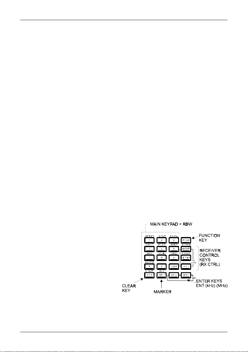
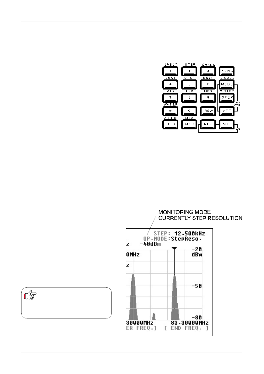
4-3 Main key layout
The main key pad consists of 20 individual
keys, each conveniently located for ease of
operation:
ê Function key (FUNC) on the top right
ê Receiver control keys (RX CTRL)
on the right
ê Enter key (ENT) on lower right
ê Clear key (CLR) on bottom left
The FUNC key enables activation of the second function keys. When pressed the ‘FUNC’ legend
appears in the top left corner of the LCD in reverse contrast YELLOW text.
15
Page 16
Section 4-4, 4-5, 4-6
4-4 Clear (CLR) key
The clear key (CLR) acts as back-space key to cancel each proceeding key
entry of numeric information (1 to 0, decimal-point) during entry of the start
/end frequency, entry of input sensitivity / trigger level or the marker and
numeration in the calculation mode. Pressing the clear key with no proceeding
key entry will abort the sequence. Pressing A.CLR (FUNC + CLR) will clear all
proceeding numeric entries and end the sequence.
Pressing the clear key (CLR) repeatedly in the calculation mode, marker mode
(except the instantaneous reading) and waterfall display mode will eventually
return operation to the default mode, see below.
4-5 Default mode and clear mode
The SDU5600 is configurable with a wide range of parameters. It is possible to
bring the SDU5600 to the default mode as described in the table by repeatedly
pressing the clear key.
Definition of the default mode
Marker mode Instantaneous reading
Calculation mode None
Waterfall mode No display
Pressing the clear key (CLR) will not affect the proceeding key entry in the
monitoring mode (spectrum analyser mode, step resolution mode, channel
scope mode), frequency span / frequency step, marker frequency and
demodulation mode.
4-6 When the communication with the companion receiver has failed
The SDU5600 will try to re-establish the communication with the receiver for a
couple of seconds. If unsuccessful the SDU5600 will revert itself to the default
mode as 4-5.
Default mode in the monitoring mode
When the communication between the SDU5600 and the companion
receiver has been disrupted while operating in the channel scope mode
the SDU5600 will automatically switch itself from the channel scope
mode to spectrum analyser mode, ending up in the default mode.
16
Page 17
Section 5, 5-1-1
5. Configuration of the SDU5600
The SDU5600 is designed to configure a wide range of parameters for ease of operation.
5-1-1 Configuration (CONF)
This section explains how to configure the operating environment under which the SDU5600 is used.
Selection of the receiver, Plotting pattern and Frequency direction are to be configured. Press
the FUNC key followed by the 4 (CONF) key to assign the soft keys as the following diagram.
For selection of the receiver press the RX key.
The box where the type of receiver is shown will be in reverse contrast. Rotate the
main dial to scroll through applicable receivers one after another. Press the ENT key
(kHz key or MHz key) to determine the companion receiver. There are no other features
of the RX configuration menu.
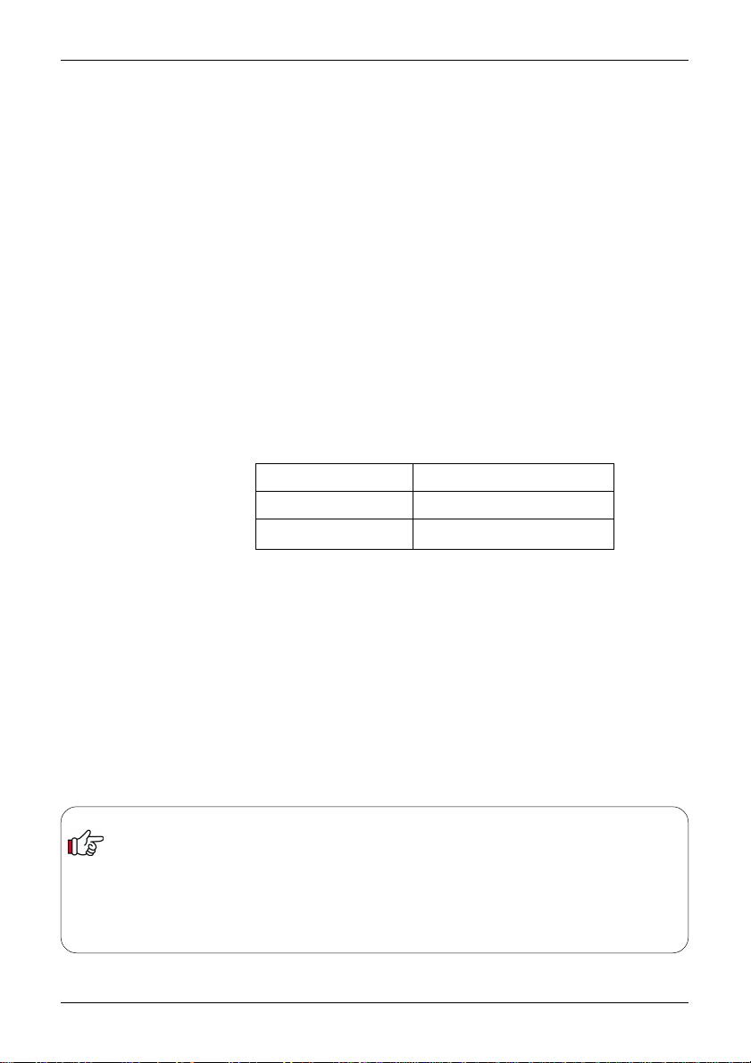
For selection of the plot pattern press
PLOT key. The present pattern is shown
either as Paint or Outline. If you wish to
change the pattern from the one to
another press the PLOT key. There are no
other features of the PLOT configuration
menu.
For selection of the frequency direction
press the F-DIR key. The present
selection is shown either as Reverse or
Normal. Press the F-DIR key to toggle
between Reverse and Normal. This
configuration is valid only when the
companion receiver has been selected as
Other(10M) or Other(45M), it is not
applicable when a ‘known’ valid radio is
connected. There are no other features of
the F-DIR configuration menu.
This illustration shows PAINT mode:
This illustration shows OUTLINE mode:
17
Page 18

Section 5-1-2
5-1-2 Applicable receivers
This is a list of compatible receivers which are selectable from the SDU5600
companion receiver menu:
Receiver Selection menu Applicable receiver Remarks
AR5000 AR5000/+3 Use of EXT-IF port
AR5000A/+3
AR3000A AR3000A 10.7MHz IF mods required
Use of 4800bps
AR8600(10M) AR8600MK2 IF mods required if used
in all modes
AR8600(45M) AR8600MK2 45MHz IF mods
(TV mods) required
AR8200 AR8200MK3 45MHz IF mods
(TV mods) required
AR-ONE AR-ONE
RFU5600 RFU5600 Built-in RF adaptor
IC-R8500 IC-R8500
IC-R7100 IC-R7100 CT-17 required
Other(10M) Receiver with Frequency direction
10.7MHz out selectable
Other(45M) Receiver with Frequency direction
45.05MHz out selectable
Non-AOR receivers are excluded from our terms and condition which are applicable
to AOR receivers in respect of electrical performance and specifications.
For modifications, please contact AOR:
Japan
AOR Ltd, T el: +81 3 3865 1695 www .aorja.com
Europe
AOR (UK) Ltd, T el: +44 1773 880788 www .aoruk.com
Americas
AOR USA INC., T el: 310 787 8615 www .aorusa.com
18
Page 19

Section 5-2-1
5-2-1 Configuration of the Receiver
This section explains how to configure the
companion receiver itself. Note that this section
will not apply when Other(10M) or Other(45M)
has been selected in the receiver selection
menu, or communication has not been correctly
established between the SDU5600 and companion
receiver.
On the right of the main keypad there are three
control keys which directly affect the operation of
the companion receiver, these are MODE (receive
mode), STEP (tuning step) and ATT (attenuator).
Their operation in companion with the SDU5600
is described below.
Receive (Demodulation) mode - MODE
This key is used to select the receive mode of the companion receiver (NFM, AM etc). Press the
MODE key to activate the RX.MODE menu, the corresponding LCD legend flashes in reverse
contrast. Rotate the main dial to scroll the various receive modes. Press the ENT key to accept the
displayed the receive mode.
Frequency step - STEP
This key is used to select the tuning step size of the
companion receiver . Press the STEP key to
activate the RX.STEP menu, the corresponding
LCD legend flashes in reverse contrast. T ap in the
step size via the ten-keys then press the ENT key.
Any step size which is not supported by the
companion receiver will be rejected by the
SDU5600 and the LCD will revert to the previous
step size.
Attenuator - ATT
This key is used to activate or deactivate the attenuator of the companion receiver as a toggle, each
push of the ATT key will alternate On/Off and the corresponding LCD legend RX.ATT will confirm the
status.
AUTO mode of the companion receiver
When the companion receiver is equipped with an auto mode feature where the IF filter bandwidth
and receive mode can be changed independently (such as the AR5000A), the SDU5600 cannot
make changes to the IF bandwidth. For this reason, it is suggested that auto mode be used or the
bandwidth selected manually if only one receive mode is to be used while operating with the SDU5600
in the current session.
Revert to the parameters which have been previously configured
ê Press FUNC + S.MODE/MODE to revert to the previously selected receive mode.
ê Press FUNC + S.STEP/STEP to revert to the previously selected receive tuning step size.
ê Note, these facilities do not operate once the SDU5600 has been switched off and on.
Value of the attenuation (amount of attenuation)
The amount of attenuation is determined by the attenuator of the companion receiver. With the AR5000
series receiver the attenuation can be manually selected from the receiver’ front panel. However when the
attenuator is switched on from the SDU5600’s front panel it will select only the AUTO position of the
receiver.
19
Page 20
Section 5-2-2
5-2-2 Selecting the receive frequency
This section will explain how to select and monitor the receive frequency of the companion receiver.
It must be noted that the SDU5600 employs the following principle:
Spectrum / Step Resolution - Receive Frequency (RX.FREQ) = Centre Frequency (CF)
Method 1: While the SDU5600 is in SPECTRUM MODE (default when first switched on) or STEP
RESOLUTION MODE, use the ten keys to directly enter the desired centre frequency, followed by
the kHz or MHz key to complete the sequence.
Method 2: Usually the main dial changes the position of the marker, however press the
CENTRE FREQ. soft key to display the
below), now you can alter the centre frequency by turning the
the
keypad
frequency step selected in the receiver), 20kHz in the example below. While tuning the
receive frequency or CF by rotating the main dial there may be up to approx. 2
seconds of delayed response between the SDU5600 and the companion receiver.
Pressing the ten keys to enter the centre frequency in the following instances will be void:
ê When the FUNC legend is shown in reverse contrast.
ê When the companion receiver has been selected as Other.
ê When the SDU5600 is in the marker mode following the key press of FUNC + MK.F keys.
ê While the SDU5600 is in a process of entering calculation data.
Once the entry by the ten-keys has been made, entry by the main dial is invalid. To resume the entry by the main dial press the CLR
key once followed by the CENTRE FREQ. key.
Centre frequency and Receive frequency step:
ê The frequency step shown on the SDU5600’s screen is valid when operated by the main dial.
ê The frequency step selected by the companion receiver is valid when the SDU5600 is being controlled by the
companion receiver.
. The frequency step in use is as selected by the SDU5600 (not the
Notes: If the companion receiver is of interactive type such as the AR5000 series the centre frequency can be operated
via the receiver’s tuning dial (or keypad depending on level on inter-operability). The frequency step in such use is as
selected by the receiver (the diagram below shows a tuning step of 100kHz).
Receive frequency cannot be adjusted when the companion receiver has been selected as Other(10M) and Other(45M),
the soft keys change colour to dark blue and the main keypad will not initiate frequency entry... producing an error beep
if the feature is enabled. This is also true when communication between the SDU5600 and the companion receiver has
been disrupted.
CF legend
in reverse contrast (as diagram
main dial
as well as via
FUNC + 1
Spectrum
mode
FUNC + 2
Step
Resolution
mode
20
Page 21
Section 5-2-2
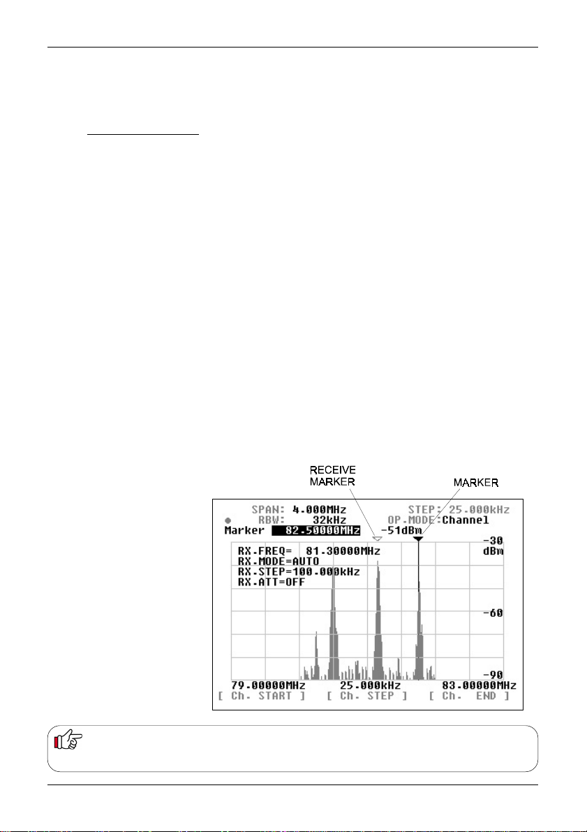
Channel scope mode
The previous page explains the receive frequency operation in the spectrum analyser mode and step
resolution mode. The channel scope mode differs since it does not use the centre frequency (CF),
instead the receive frequency equals the marker position:
Channel Scope Mode - Receive Frequency = Receive Marker position
In addition, by use of the marker receive key MK.F you can track and select any active receive
frequency for monitoring within the frequency band presently shown on the screen.
FUNC + 3 selects
The currently selected centre frequency will become the new START frequency, the CHANNEL
STEP is default 100kHz, the bandwidth is initially selected as 5MHz. Y ou can change the start
frequency, channel step and end frequency ... or just press ENT three times to accept the current
defaults.
Use the SDU5600 main dial to select a peak on the display to indicate the presence of an active
channel, press MK.F to receive the new frequency. As you move the main dial again, you will note
that a new yellow-outline marker appears at the current position on the display, this is the receive
marker. You can toggle the display line to confirm RECEIVE MARKER frequency or MARKER
frequency position using the key sequence FUNC + MK.F (MK.R). When RECEIVE MARKER is
selected, a green dot is displayed on the LCD.
The channel scope mode cannot be selected when the companion receiver has been selected as
Other(10M) or Other(45M), or the communications between the SDU5600 and the companion
receiver has been disrupted.
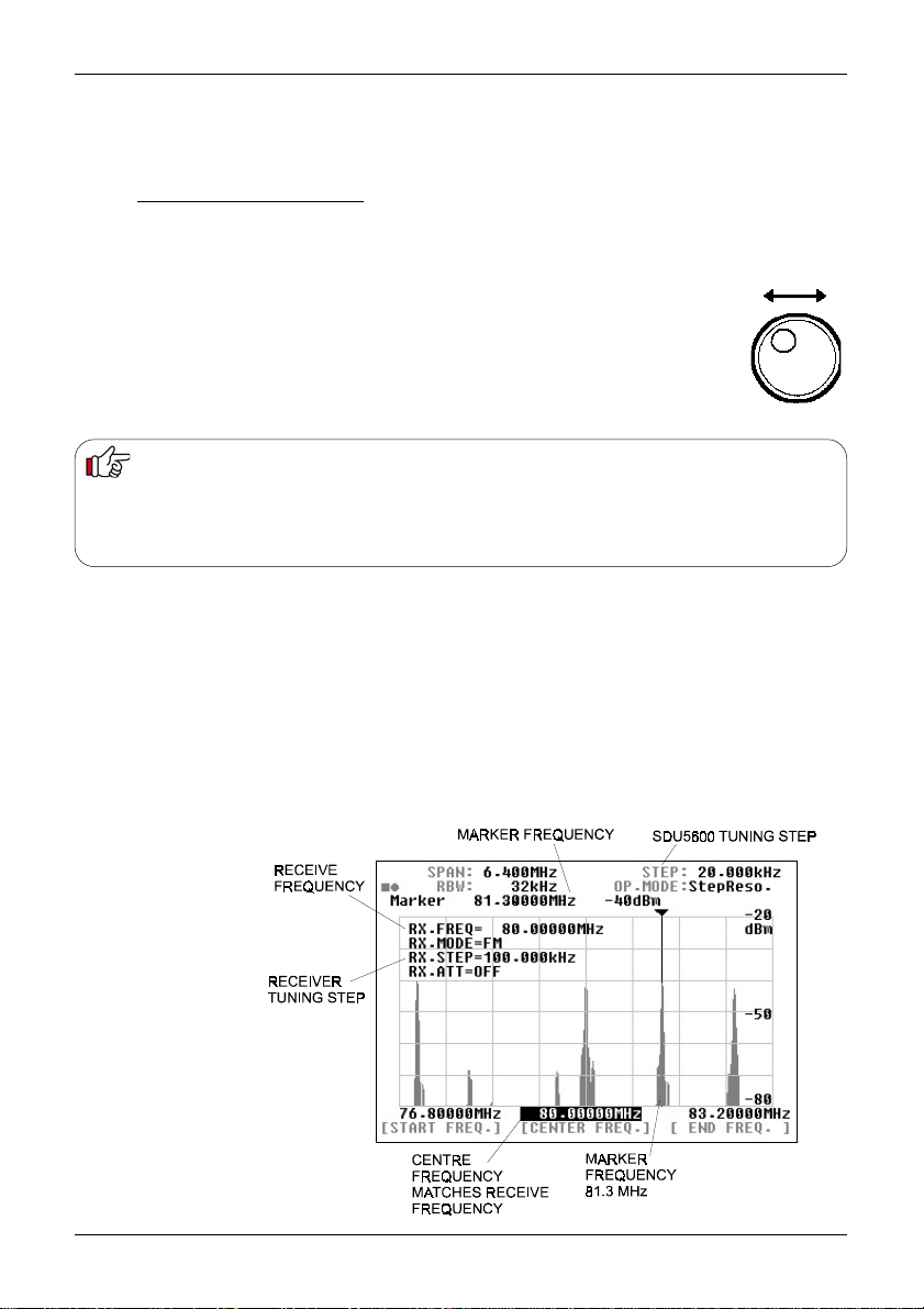
The example of the channel scope mode here displays the following parameters:
Receive marker = 81.3MHz
Receive frequency = 81.3MHz
Marker position = 82.5MHz
Start frequency = 79.0MHz
Channel step = 25kHz
End frequency = 83.0MHz
Channel Scope mode
Receive marker [MK.F] key
In the spectrum analyser mode and step resolution mode press the MK.F key to swap the marker frequency for the
centre frequency (CF). This is convenient if you wish to listen in the marker frequency immediately.
21
Page 22
Section 5-3
5-3 Setup of the monitoring mode
The SDU5600 is designed to provide 3 different monitoring modes such as the spectrum analyser
mode, step resolution mode and channel scope mode. Choosing the most appropriate monitoring
mode for your specific requirements is important to maximise performance and efficiency of the
SDU5600.
Method of selecting each monitoring mode:
Spectrum analyser mode Press FUNC + 1 (SPECT)
Step resolution mode Press FUNC + 2 (STEP)
Channel scope mode Press FUNC + 3 (CHANL)
The 1, 2 and 3 keys are allocated with the
function’
. The selected mode is displayed on the second
line from the top-right side of the LCD as OP.MODE
Each mode has unique features.
Spectrum analyser mode (SPECT)
This is most suited for general listening and to hunt for non specific signals or noise,
by sweeping across the defined range of spectrum (up to a bandwidth of 10MHz).
Step resolution mode (StepReso)
This is most suited to monitor specific signals across a known relatively wide defined
band where signals are allocated with a certain stepping size, for example VHF
airband. The horizontal x-axis of the LCD has a resolution of 320 dots, each dot
represents one step, so there are a total of 320 steps.
‘second
Channel scope mode (Channel)
This is most suited to monitor a
known narrow channelised band of
frequencies such as the VHF or UHF
amateur band. Channel scope mode
can emulate almost a real-time band
scope between the start and end
frequency with defined stepping size.
When the companion
receiver has been selected
Other
as
the channel scope
mode is disabled.
22
Page 23

Section 5-4, 5-4-1
5-4 Basic setup for each monitoring mode
This section will explain how each monitoring mode has to be set up.
5-4-1 Spectrum analyser mode
Example of the screen is shown here, the
parameters are as follows:
Centre frequency (CF) = 122.5MHz
Frequency span = 10.0MHz
Start frequency = 117.5MHz
End frequency = 127.5MHz
Marker frequency = 123.5MHz
Operating step = 31.25kHz
Centre frequency (CF)
Press the CENTRE FREQ. key to make the
centre frequency display read-out appear in
reverse contrast. Enter a desired frequency via
the ten-keys followed by the kHz or MHz key,
this is now the centre frequency. The main dial
of the SDU5600 may also be used to select a
frequency, you must still use the kHz or MHz
key to complete the frequency entry sequence.
Assuming that communication between the
SDU5600 and the companion receiver has
been correctly established, the centre
frequency of the SDU5600 becomes the
receive frequency of the companion receiver.
Frequency span (SPAN)
Press the SPAN/STEP
Enter the frequency span (range / bandwidth), over which you wish to monitor using the ten-keys followed by the kHz or MHz key
to confirm the entry. Once the frequency span has been entered the display step will be automatically calculated and displayed as
STEP
on the top line of the LCD to the right of the
special key
to reverse the contrast of SPAN numeric display on the top line of the LCD.
SPAN
.
Start frequency and end frequency
The START and END frequency can be entered in the same manner as the centre frequency entry using the assigned soft keys,
ten-keys and ENT key. The main dial is not valid for the entry.
Special key - CENTRE FREQ.
This hardware special key is a duplicate of the soft key CENTRE FREQ. and has identical action. Either key may be used to the
same effect.
Enter key MHz/kHz
SDU5600 has TWO ENTER KEYS, either may be used to complete key sequences. When inputting frequencies, you may use kHz
or MHz format. For example, ten-MegaHertz may be entered as:
1 0 MHz
or
1 0 0 0 0 kHz
Example of the automatic calculation of the display step
In the above illustration, the frequency SPAN is 10MHz, so the STEP (incremental resolution of the horizontal x-axis) is automatically
calculated as:
10MHz divided by 320 = 31.25kHz
23
Page 24
Section 5-4-2
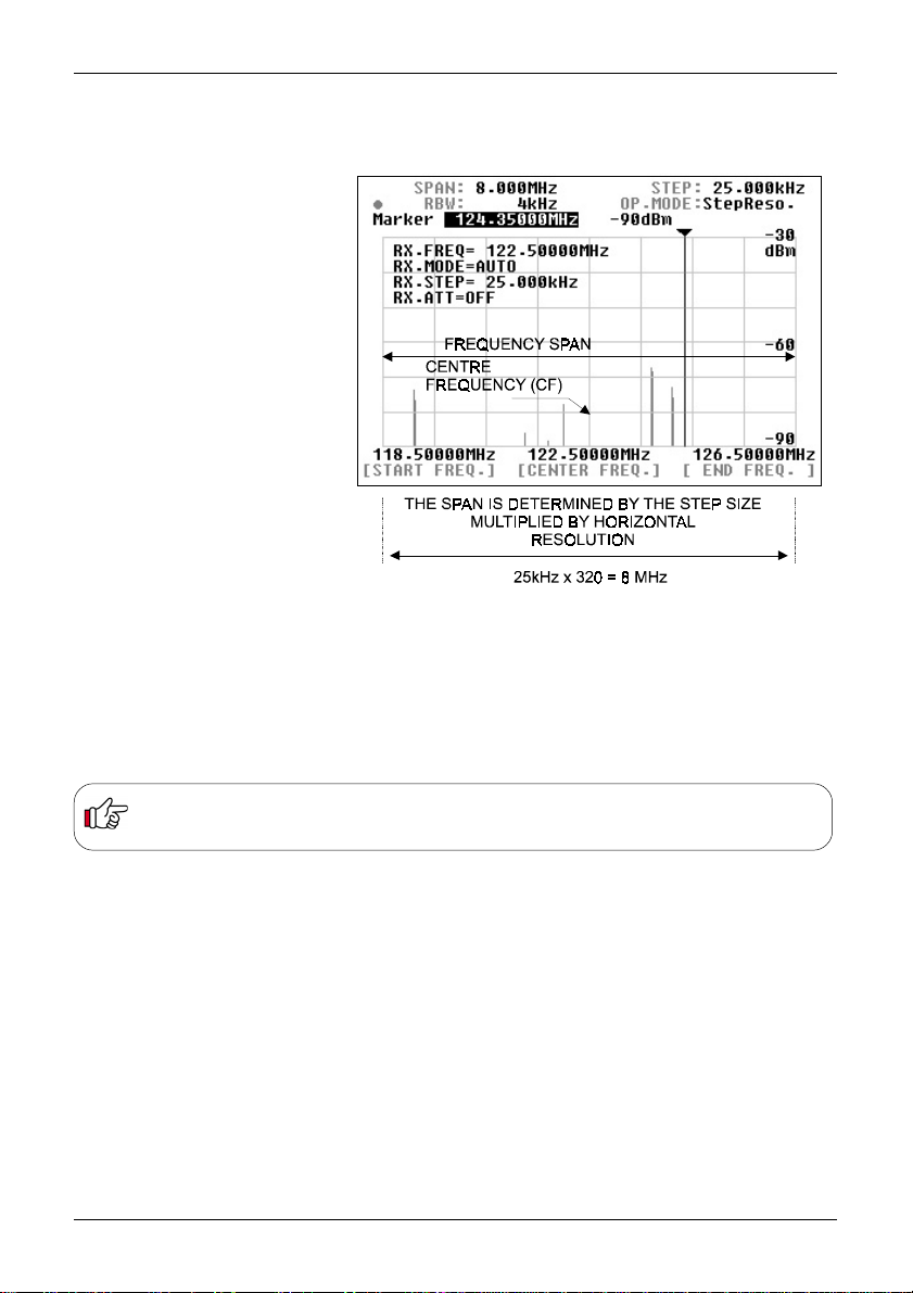
5-4-2 Step resolution mode
Example of the screen is shown here, the parameters are:
Centre frequency (CF) = 122.5MHz
Display step = 25kHz
Frequency span = 8MHz
Start frequency = 118.5MHz
End frequency = 126.5MHz
Marker frequency = 124.35MHz
In the step resolution mode, the frequency
span is determined by the entry of display
step size, which is OPPOSITE to the
spectrum analyser mode where the
display step size is determined by the
entry of frequency span.
Centre frequency (CF)
Press the CENTRE FREQ. key to make
the centre frequency display read-out
appear in reverse contrast. Enter a
desired frequency via the ten-keys
followed by the kHz or MHz key, this is
now the centre frequency. The main dial
of the SDU5600 may also be used to
select a frequency, you must still use the
kHz or MHz key to complete the
frequency entry sequence.
Assuming that communication between
the SDU5600 and the companion
receiver has been correctly established,
the centre frequency of the SDU5600
becomes the receive frequency of the
companion receiver.
Display step (STEP)
Press the SPAN/STEP
Enter the frequency step size, using the ten-keys followed by the kHz or MHz key to confirm the entry. Once the frequency step has
been entered, the display step will automatically calculate the SPAN and display STEP and SPAN on the top line of the display.
special key
to reverse the contrast of STEP numeric display on the top line of the LCD.
Note: If you select a step size which is too large, the SDU5600 will default to 31.250kHz step with span of 10MHz... and
will produce an error beep (if the beep facility is enabled). If you select a step size which is too small, the SDU5600 will
default to 0.500kHz step with span of 0.160MHz... and will produce an error beep (if the beep facility is enabled).
Special key - CENTRE FREQ.
This hardware special key is a duplicate of the soft key CENTRE FREQ. and has identical action. Either key may be used to the
same effect.
Effective frequency coverage of the companion receiver
The frequency spread (both sides of the centre frequency) must be contained within the frequency coverage of the companion
receiver. If exceeded, correct monitoring will be impossible.
Display frequency bandwidth is obtained by the following formulae:-
In the spectrum analyser mode: CF +/- (Frequency span divided by 2)
In the step resolution mode: CF +/- (Display step x 160)
Example of the automatic calculation of frequency span
In the above illustration, the frequency STEP is 25kHz, so the SPAN is calculated by the SDU5600 as:
25kHz x 320 = 8MHz
where 320 is the horizontal x-axis resolution of the LCD.
.
24
Page 25
Section 5-4-3
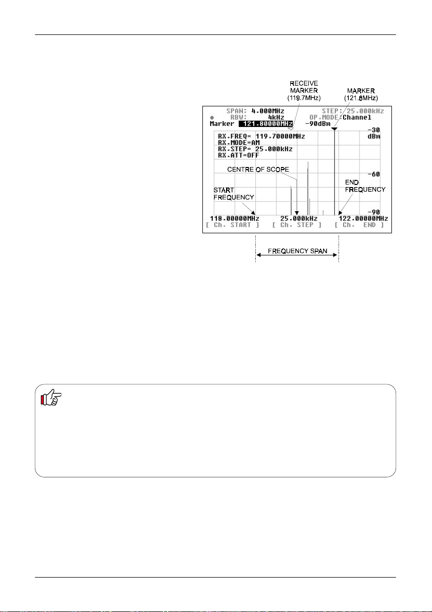
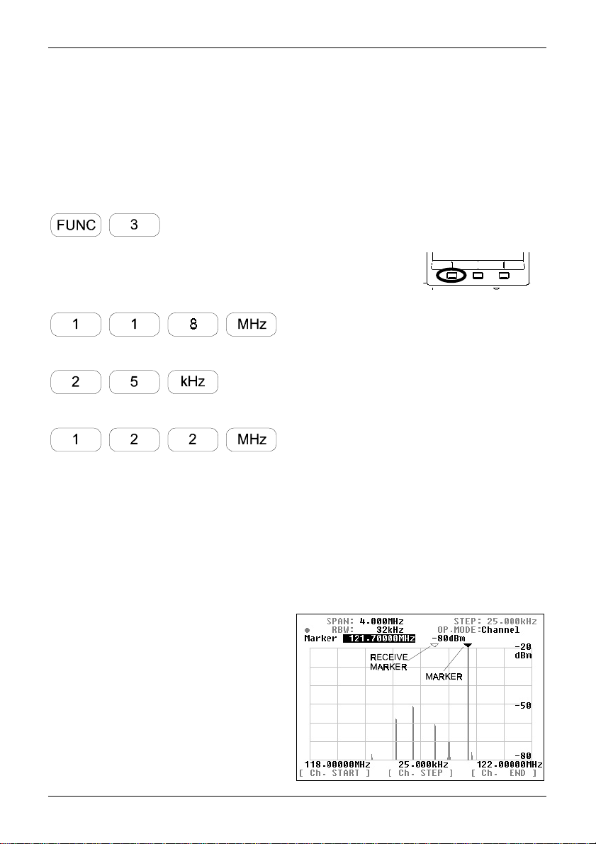
5-4-3 Channel scope mode
Example of the screen is shown here, the parameters are:
Start frequency = 118.0MHz
Step frequency = 25kHz
End frequency = 122.00MHz
Frequency span = 4MHz
Marker frequency = 121.8MHz
Receive marker = 119.7MHz
Unlike the spectrum analyser mode or step resolution
mode there is no centre frequency (CF) in the channel
scope mode.
Start frequency (Ch.START)
Press the Ch.STAR T key to make the start frequency
read-out display appear in reverse contrast. Enter a
desired frequency using the ten-keys, which is the
lowest of the frequency spread you wish to monitor
(start frequency), followed by ENT to confirm.
Step frequency (Ch. STEP)
Press the Ch.STEP key to make the step frequency
display red-out appear in reverse contrast. Enter the
desired step frequency of your choice using the tenkeys followed by ENT to confirm.
End frequency (Ch.END)
Press the Ch.END key to make the end frequency display read-out appear in reverse contrast. Enter a frequency, using the ten-keys,
which is the highest of the frequency spread you wish to monitor (end frequency), followed by ENT to confirm.
Receive frequency (RX.FREQ)
When the channel scope mode is activated, monitoring begins on the start frequency. Rotate the main dial of the SDU5600 to move
the marker onto the signal of your interest, and press the MK.F key. The yellow receive marker moves to the nominated position and
the companion receiver monitors the wanted frequency. As the main dial of the SDU5600 is rotated, the white marker moves and the
yellow receive marker is left in position to signify the current active receive frequency. To select a new frequency to monitor, simply
press the MK.F key.
Note: The end frequency (Ch.END) is confined by the formulae:
(CH.START) + [ (Ch.STEP) x 160 ]
or
(CH.START) + 5MHz
For this reason, if you do not enter an END frequency, the SDU5600 will automatically select an appropriate end point.
Invalid entry for the end frequency will be alerted with a beep (if the feature is enabled), and the closest possible valid
frequency will be automatically chosen by the SDU5600. Similarly, any invalid entry of frequency will be alerted with the
beep (if the feature is enabled), and will be automatically adjusted to the nearest possible frequency by the SDU5600.
25
Page 26

Section 5-4-4
5-4-4 Common features shared by different monitoring
modes
Input sensitivity (AMPLITUDE)
This feature refers to the setup of the input
sensitivity level of the SDU5600 which is
adjusted by the internal amplifier of the
SDU5600. There are 4 different levels of input
sensitivity between 0dBm and -30dBm in 10dB
steps.
Press the AMPLITUDE special key to make the
reference level display appear in reverse contrast.
Enter the required sensitivity level via the
ten-keys or main dial, followed by ENT.
For example, If -20dBm is required press
AMPLITUDE 2 MHz. You can ignore trailing
zeros ‘0’ following 2 in this instance.
Any invalid entry will be alerted with the
beep, and the nearest possible value will be
automatically selected instead.
The resulting displayed signal wave on the LCD
is affected by combinations of various factors
such as input sensitivity of the SDU5600,
attenuator position and AGC setting (where
applicable) of the companion receiver. Higher
input sensitivity does not always provide the best
results. It is also possible to produce distorted
signals due to saturation to / from the companion
receiver, this may lead to a raised noise floor of
the SDU5600 or spurs.
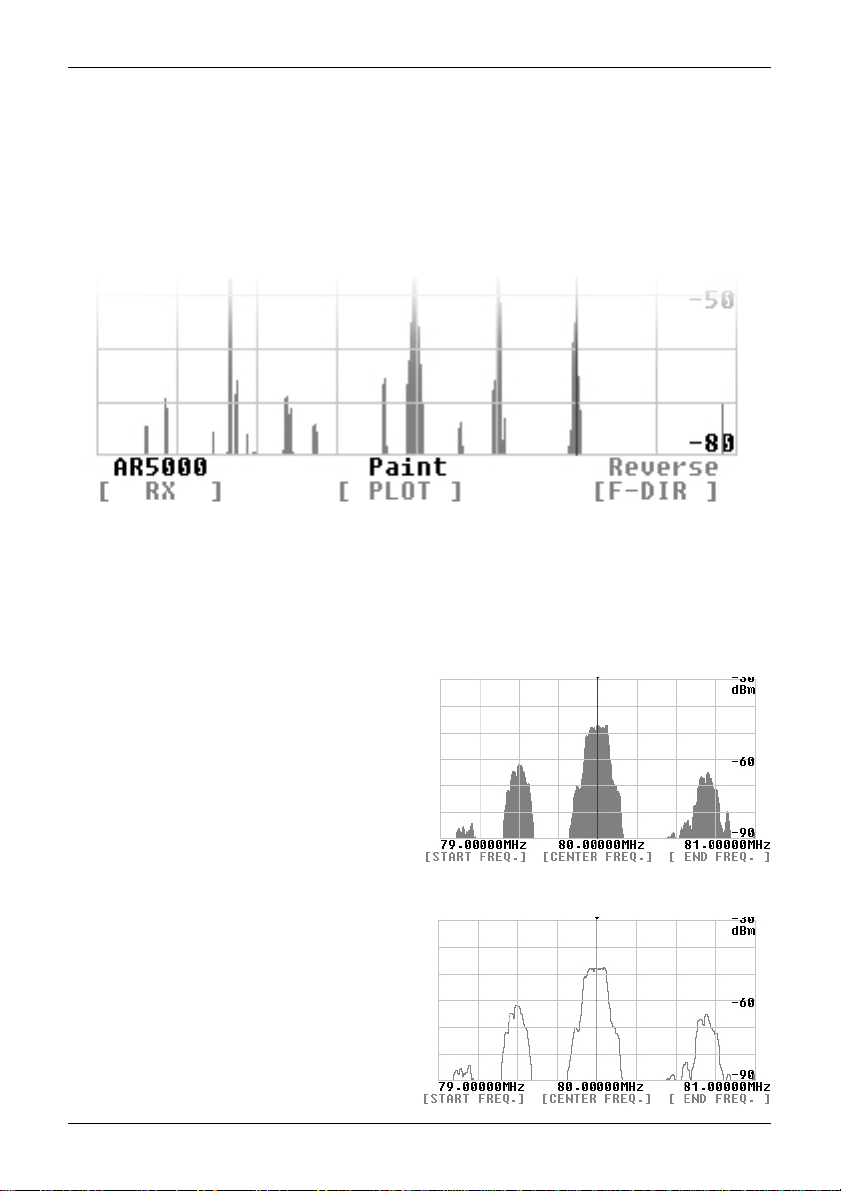
Significance of the input sensitivity
(reference level)
The two plots shown here show the results from monitoring the same signal at 80.0MHz WFM but using different
input sensitivity settings.
The plot on top was produced with the input sensitivity of -30dBm, the input sensitivity is too high, which results in
unstable operation within the RF amplifier of the SDU5600. This has produced some ghost signals (images)
separated at regular intervals.
The bottom plot was produced with the input sensitivity of -20dBm. Optimum results are obtained due to correctly
selected input sensitivity.
It is important to select the input sensitivity most appropriately to ensure best results.
The AR5000 series receivers and RFU5600 feature AGC level adjustment, however AGC level cannot be adjusted
remotely from the SDU5600.
Effective use of the attenuator of the companion receiver will be required to prevent saturation of received
signal particularly when an external aerial is used.
26
Page 27

Section 5-4-4
Resolution band width (RBW)
The SDU5600 provides four
selectable RBW bandwidths
which are 4kHz, 32kHz, 64kHz
and 128kHz.
Press the RBW key to make the
RBW display appear in reverse
contrast. Rotate the main dial to
select the desired value followed
by MHz or kHz to complete the
selection sequence.
The two plots here show the
results from monitoring the same
signal (80MHz WFM) but using
4kHz and 128kHz RBW
bandwidths respectively.
With the narrower RBW, the finer
signal activity can be observed.
With the wider RBW bandwidth
the resolution becomes coarse
but it can be more suited for
signals with wide bandwidth such
as FM broadcast signal.
The RBW should be chosen
as appropriate for different
monitoring requirements.
As the SDU5600 employs
modern DSP/FFT techniques,
there is no difference in screen
update speed irrespective of
which RBW has been selected.
However, selection of RBW may
affect the displayed signal strength.
When a signal is displayed which is much wider in bandwidth than the currently selected RBW filter,
there will be some inaccuracy in the signal strength displayed. This is because the wider signal will
loose some of its energy after passing through the narrower RBW filter. The same signal may
produce a higher signal strength on the LCD display if it has passed through (more appropriately
selected) wider RBW filter.
27
Page 28

Section 5-5
5-5 Marker
The SDU5600 has a marker facility. The
marker is often used to obtain the reading
of the frequency of interest. In addition to
the instantaneous reading, it provides the
peak detection and continuous peak
detection.
Press FUNC + MK.F to place the
SDU5600 in to marker mode operation.
Instantaneous reading Marker
Peak detection Peak
Continuous peak detection C-Peak
Instantaneous reading (Marker)
This feature is useful for many
applications. The marker can be moved
sideways by rotating the main dial.
The LCD displays the frequency and
signal strength reading where the marker
is positioned.
Peak detection (Peak)
This feature is used to detect the most
powerful signal while sweeping the
frequency spread.
Press the PEAK key, which in turn
requests a trigger level, you need to
specify what level is required. Enter the
trigger level via the ten-keys. Only signals
which are stronger than the trigger level
you specified will then be subject to the
peak detection.
The marker will be forced to the position
of the strongest signal detected and end
its sweep sequence.
The trigger level is selectable from
-90dBm to 0dBm in 1dBm steps.
Entry is via the ten-keys and the sequence
is confirmed by ENT
28
Page 29

Section 5-5
Continuous peak detection (C-Peak)
This facility is designed to continue the peak signal detection process one sweep after another.
Press the C-Peak key to activate the facility. There is no trigger level setup in the process.
T o return to the instantaneous
reading either from the peak
detection mode or continuous
peak detection mode press the
CLR key... depending on the
operating configurations a multiple
press of CLR may be required.
Marker receiver (MK.F)
This facility is designed to force the
companion receiver to receive the
signal where the marker is
positioned on the screen. There
are slight variations in functionality
monitoring mode-by-mode.
MK-CF
In the
spectrum analyser mode
(marker to centre frequency) which forces the marker frequency to become the centre frequency.
and
step resolution mode
the key it works as
MK > CF
MK-RF
In the channel scope mode the key works as
companion receiver will receive the marker frequency. The start frequency , channel step and end
frequency are unaffected, so will continue monitoring in the channel scope mode as configured.
MK.F key functions
Spectrum analyser mode
Step resolution mode
Channel scope mode
When the continuous peak detection is being used in the channel scope mode, the marker will
automatically move to the strongest signal detected in the process of sweep. Press the MK.F key to
automatically tune the companion receiver to the strongest signal instantly, so that you can monitor
the active frequency.
MK > RF
(marker to receive frequency) where the
29
Page 30

Section 5-6
5-6 Calculation facility
Maximum value hold (MAX)
Press the FUNC +7 keys to activate this
facility, the legend MAX will be displayed
on the graticule section of the LCD.
Press the CLR key to exit from max hold.
Without the MAX feature being used, each
new sweep across the frequency spread
will renew the signal activities over and
over. However , with the MAX feature in
use each sweep will be retained as data is
built-up until the process ends. This is
particularly useful to detect intermittent
signals which come and go over a period
of time.
Averaged value (A VR)
Press the FUNC + 8 keys to activate this
facility, the legend AVR will be displayed
on the graticule section of the LCD.
Y ou are required to enter a sampling cycle
between 2 and 31 to produce averaged
results.
Press the CLR key to exit.
This facility is designed to provide the plot
pattern which has been obtained by
averaging the detected signals repeated
over the number of times in the sampling
cycle. This facility enables the SDU5600
to produce a stable signal pattern even if
each signal is fluctuating in signal strength.
Median (MED)
Press the FUNC + 9 keys to activate this facility, the legend MED will be displayed on the graticule
section of the LCD. The plot is designed to provide the signal pattern based over a sampling cycle
of between 2 and 4 and is useful to plot impulse noise. The sampling cycle can be entered via the
ten-keys followed by ENT Press the CLR to exit.
Theory of median filter
AVR N = 31
FIRST SWEEP PLOT AS THE SWEEP PROGRESSES
SECOND SWEEP (1 + 2) / 2 = A
THIRD SWEEP (1 + 2 + 3) / 3 = B
:::
30TH SWEEP (1 + 2 + 3 + ..... 30) / 30 = A1
31ST SWEEP (1 + 2 + 3 + ..... 30 + 31) / 31 = B1
32ND SWEEP ((B1 X 31 / 32) + 32) / 32
30
Page 31

Section 5-7
5-7 Waterfall display facility
The SDU5600 is equipped with a waterfall facility which can display the variation of signal strengths in
conjunction with the time lapsed (as sweeps progress). Sixteen different colours are employed
dependant on signal strength, in the shape of a waterfall.
Press the FUNC + to start the waterfall display. The bottom half of the screen will be allocated to
the waterfall display and will build-up with time.
The waterfall display continues to operate being unaffected by change of the monitoring mode,
calculation mode, the RBW, centre frequency , frequency span, start frequency and end frequency .
T o exit from the waterfall display, repeat the key sequence FUNC +
Signal strength is represented by sixteen different colours, corresponding to the height of each signal
in the vertical scale. Therefore the colour will vary when the input sensitivity (AMPLITUDE) has been
altered in the course of monitoring.
While the waterfall display is in operation, the only parameter of the companion receiver which can be
altered is the receive frequency.
T o exit from the waterfall display, repeat the key sequence FUNC + or press CLR
31
Page 32
Section 5-8, 5-9, 5-10
5-8 On/off of the displayed information
The companion receiver parameters
are usually displayed on the left side of
the LCD graticule. The key sequence
FUNC + 5 (DISP) will toggle the display
of the companion receiver’s parameter
on / off.
When the calculation mode is in use,
the calculation data will be turned on or
off by the same key-in sequence.
By effective use of this facility, you can
view the signal activities easier on the
much less cluttered display area.
5-9 Beep alert
To toggle the keypad confirmation beep on / off, use the key sequence
FUNC + 6 (BEEP).
5-10 Factory default/reset
If you wish to revert the SDU5600 to
default status, power-on the SDU5600
via the main power switch while
holding-in the 3 and 6 keys together
until the opening message EEPROM
initialized is displayed.
32
Page 33
Section 6, 6-1
6. Operating the SDU5600
This section will provide examples of operating the SDU5600 using the AR5000A+3 as companion
receiver. Refer to pages 10 to 12 of this manual for connection to the receiver .
6-1 Operate the SDU5600 with
the AR5000A+3.
Turn the SDU5600 on, which
is followed by the opening
message to confirm for
readiness.
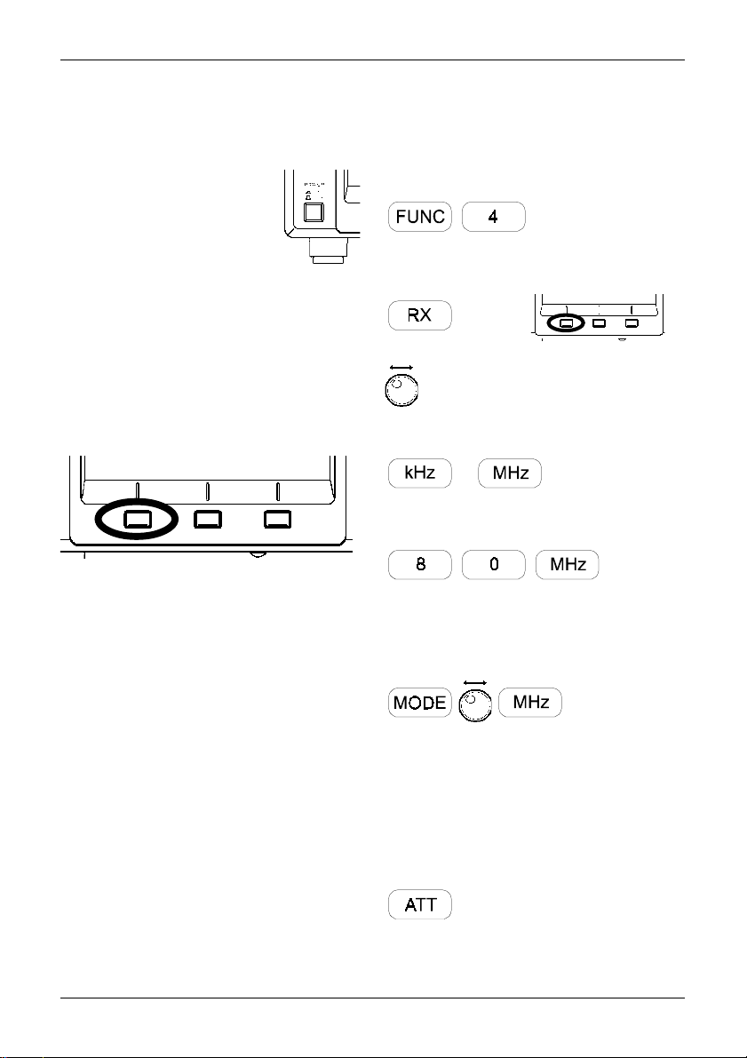
Access the configuration menu by pressing the
FUNC + 4 to select the companion receiver.
Press the RX key, which displays the current
companion radio type above the key on the LCD
in reverse contrast. Select the AR5000 (in this
example) via the main dial followed by ENT.
The communication between the two should be
correctly established so that you can start
monitoring.
At this stage the SDU5600 is operating in the
spectrum analyser mode with the centre
frequency (CF) corresponding to the receive
frequency of the AR5000A+3. The frequency
span (visible bandwidth) is 10MHz.
Setup of the companion receiver
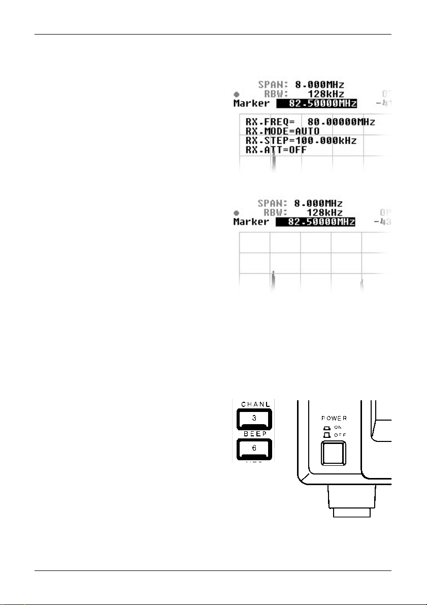
Continue to operate the AR5000A+3 via the
SDU5600 referring to the following example:
RX.FREQ. = 80.00000MHz
RX.MODE = AUTO
RX.STEP = 100.000kHz
RX.A TT = OFF
The SDU5600 can remotely operate the
following functions of the companion receiver.
ê Receive frequency
ê Receive mode
ê Frequency step
ê Attenuator on/off
Other functions such as the antenna
switching are not possible.
Access the conflagration menu
Selection of the companion receiver soft key
Rotate the main dial to select the
companion receiver
Confirm the selection of the companion receiver
or
Enter the centre frequency CF (80MHz)
Press the MODE key to access the receive
mode menu. Select the receive mode by
rotating the main dial to AUTO followed by MHz
In this example, the AUTO mode will select a
receive mode of FM and frequency step of
100kHz.
T o toggle the attenuator on/off, press the
attenuator key
33
Page 34
Section 6-2
6-2 Monitor the VHF FM band in the spectrum analyser mode
Continue to operate the SDU5600 from section 6-1 where the SDU5600 / AR5000A+3 has been set
in the spectrum monitoring mode.
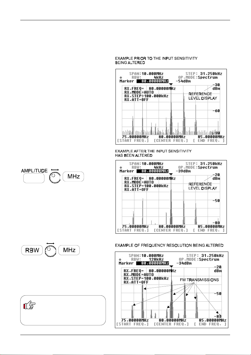
The example to the right is the actual
result which was obtained after
monitoring the signal spectrum at the
AOR headquarters in T okyo. It indicates
the input signal being saturated,
resulting in some weak ghost signals
appearing at regular intervals close to
the floor level of the spectrum trace.
Adjust the input sensitivity
(from -30 to -20)
Press the AMPLITUDE key to display
the reference level on the LCD, which
appears in reverse contrast (-30dBm).
Rotate the main dial to select -20dBm
which lowers the input sensitivity by
10dB followed by ENT
(MHz or kHz)
Adjust the resolution bandwidth
(from 4kHz to 128kHz)
Press the RBW key to display the
resolution bandwidth value on the LCD,
which appears in reverse contrast
(4kHz). Rotate the main dial to select
128kHz followed by ENT
The example on the right now shows the
same result with the RBW set to
128kHz, this bandwidth is far more
suitable for monitoring FM broadcast
signals with wider band occupancy.
Refer to page 23, section 5-4-1
should you wish to operate the
CF , frequency span, etc in the
spectrum analyser mode.
(MHz or kHz)
34
Page 35
Section 6-3
6-3 Monitor the FM broadcast band in the step
resolution mode
The following information explains how to change the monitoring mode from
the default of spectrum analyser mode to the step resolution mode.
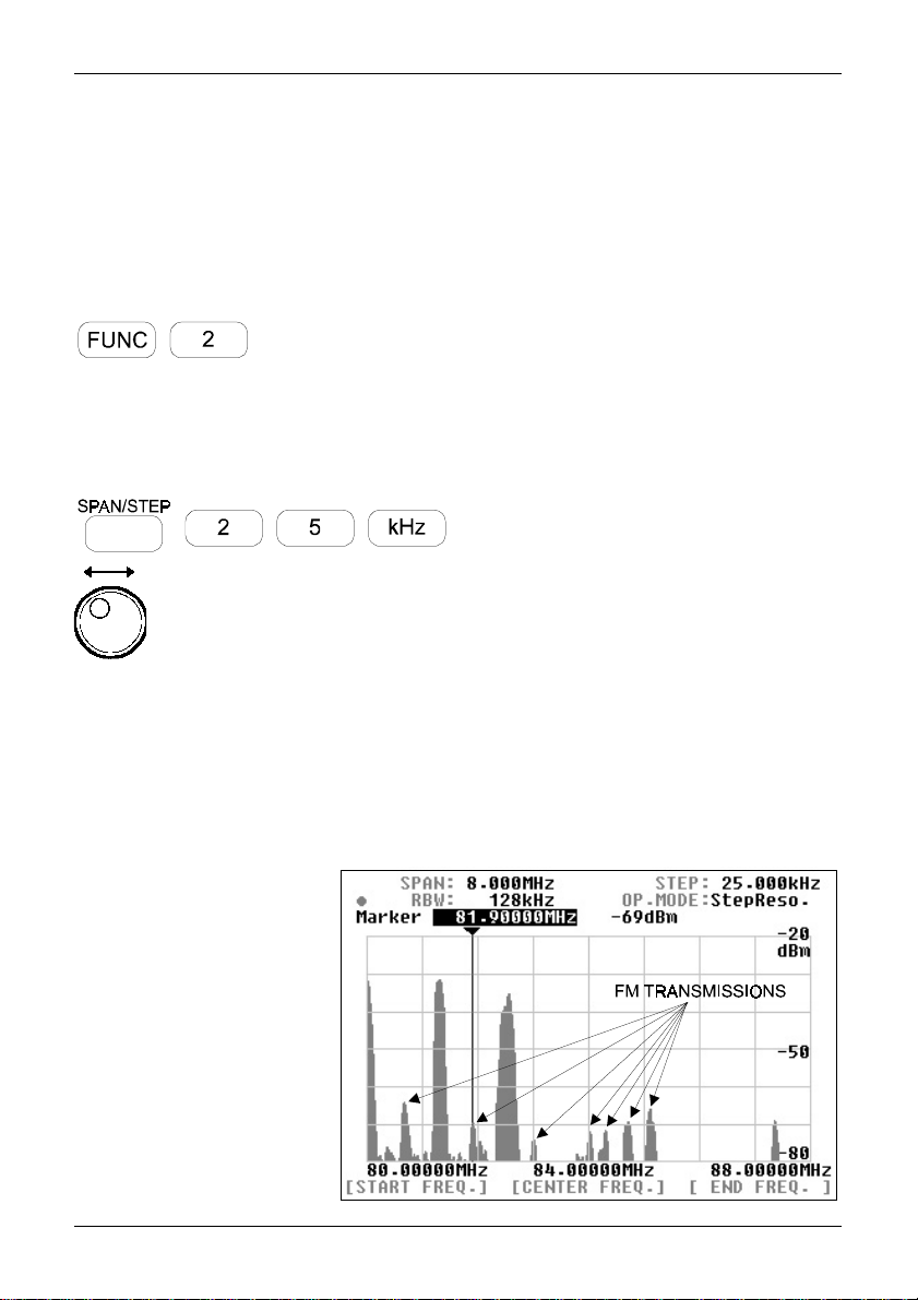
Press the FUNC + 2 (STEP), the SDU5600 will shift to Step Resolution mode
with the legend
unchanged at this stage.
You may wish to change the display step to a 25kHz in order to make the task
of monitoring easier. Press the SPAN/STEP key, which results in the step
display appearing in reverse contrast on the LCD. Type in the required step
size via the ten-keys, in this example 2 5 followed by kHz
In the step resolution mode the rule is:
1 displayed dot = 1 displayed step
The horizontal x-axis of the SDU5600 provides 320 dots.
Therefore in the above example, one displayed dot represents one 25kHz
increment. The step resolution mode provides a kind of operating convenience
where the operator can almost instinctively view activity on the band and
how the activity is
distributed.
The example on the
right shows the signal
activities observed at
the AOR headquarters
in Tokyo over the FM
broadcast band in the
step resolution mode.
Refer to page 24,
section 5-4-2 should
you wish to operate the
CF, display step, etc.
StepReso.
Rotate the main dial to move the marker sideways. It should be
immediately noticeable that the frequencies on active signals can be
found in 25kHz steps, which is much more suitable for monitoring
channelised bands such as FM broadcast.
appearing on the LCD. The display step will be
35
Page 36
Section 6-4
6-4 Monitor the VHF air band in the channel scope mode.
The VHF airband is allocated over the wide frequency band, It is therefore impossible to display the
entire VHF airband on the SDU5600 at once. The channel scope mode however provides a very
convenient method of monitoring the channelised frequency band through the use of both the marker
and receive marker. Using this method, you can split the airband into small sections for quick
inspection.
Change of the monitoring mode
T o change to Channel Scope mode press FUNC + 3 (CHANL). The LCD legend
channel scope mode has been engaged.
The LCD legend above [Ch.START] will display a frequency in revers contrast, this
is inviting you to key in a new start frequency via the ten-keys.
Enter a start frequency of 118MHz, if you make a mistake, press CLR to return to
the start entry position.
The LCD entry point will move to [Ch.STEP], enter a step frequency of 25kHz
The LCD entry point will move to [Ch. END], enter an end frequency of 122MHz
OP .MODE:Channel
confirms that
Note, the end frequency is always restricted under the rules:
Any incorrect entry of the end frequency will be alerted with the beep, and it will be automatically corrected to the
nearest possible frequency.
Upon the successful entry of the end frequency the companion receiver will commence receiving on the start
frequency. Change the receive mode to AM for air band if required (or use AUTO mode), use the MODE key , main
dial or SDU5600 and MHz key.
Rotate the main dial, which moves the marker
sideways. The
(yellow outline triangle on the LCD) to indicate the
frequency which the companion receiver is actually
receiving.
Press the MK.F key to move the receive marker to
the marker position, this will move the companion
receive to the new frequency where monitoring will
continue.
East time you press the MK.F key , the companion
receiver will shift to the marker position, as you move
the marker by rotating the SDU5600 main dial, two
markers will be displayed on the LCD. You can
change the parameters at any time by pressing the
corresponding soft key under the LCD.
receive marker
legend appears
(CH.START) + [(CH.STEP) x 160]
and
(CH.START) + 5MHz
36
Page 37

Section 6-5
6-5 Suitable applications of each monitoring mode
A summary of the three monitoring modes and suitable applications is given
here:
Spectrum analyser mode
This mode is the DEFAULT and most common monitoring mode among the
three. It is suited to the monitoring of permanent or intermittent signals or
noise. The CF (centre frequency) and SPAN (visible bandwidth) are the main
criteria to be specified.
Step resolution mode
This mode is suited best to monitor signals which are allocated with certain
intervals over the band spectrum. The STEP is the criteria to be specified in
place of the SPAN, so that one dot is equal to one step on the display.
Channel scope mode
This mode is best suited to monitor known channelised frequency spectrums
such as VHF airband and FM sections or broadcast and ham radio bands.
The start frequency, end frequency and step have to be specified. There is no
concept of CF applied to this mode. It is most convenient to follow and listen
to the various signals by using both marker and receive markers.
37
Page 38

Section 7
7. Useful Information
The SDU5600 has been designed to operate with a wide-band companion receiver such as the
AR5000A. Therefore, there are some differences in operating characteristics with the unit when
compared with the spectrum analysers which are designed for more general testing / measuring
applications. It is advisable that you take into account the following information while making yourself
familiar with the SDU5600.
Signal strength
The signal strength which the SDU5600 indicates is measured at the RF input of the SDU (not the signal strength of the companion
receiver at the antenna terminal). If the radio provides a gain / loss from the aerial input to IF output, the calibration of displayed signal
strength will be affected. Most receivers provide a POSITIVE gain of +10dB or so. The receivers AGC and attenuator will also affect
results.
Frequency characteristics of the companion receiver
The SDU5600 operates with a wide span of frequency (up to 10MHz band span). It must be noted that the companion receiver’s RF
circuit and / or IF filter configuration may affect the spectrum monitoring with some interference being observed. In particular, when the
wider band span has been selected such as a 10MHz, the far ends of the band edges are most affected depending on characteristics
of the receiver in use. The AR5000A is usable over 10MHz bandwidth, as is the AR3000A, however the output level of the AR8600/
MK2 drops beyond 4MHz or so.
Excessive input from the receiver
While receiving strong signals (e.g. broadcast station) with an external aerial connected to the companion receiver, the noise floor
may appear to be incorrectly lifted due to distortion from the receiver. Use of the attenuator of the receiver may help reduce these
phenomena... however, generally speaking the front end selectivity of the companion receiver is beneficial compared to a direct ly fed
spectrum analyser.
Selection of RBW
When monitoring the signals of broader bandwidth with the narrower RBW selected, the displayed signal strength may appear
reduced (less accurate) due to the fact that only part of the energy from the broader bandwidth can pass through the narrower
sampling filter, resulting in loss of signal strength to some extent. When monitoring wider signals (such as FM broadcast), use a wider
RBW such as 128kHz.
AGC action of the companion receiver
It must be noted that the AGC action of the companion receiver may affect the spectrum monitoring by the SDU5600. It may be
observed that the overall signal strength has dropped when abrupt changes in receiving conditions have occurred (for example, when
quickly tuning from a weak signal to a strong signal). This is because the input from the receiver’s IF is significantly reduced by AGC
action. Switching the companion receivers AGC off may eliminate this effect but the reception will become unstable and distorted with
AGC off.
Image signal
Occasionally false signals (spurious image signal) can be spotted on the display, sometimes moving at random, sometimes to the
opposite direction while monitoring the spectrum. This is due to the image signals which are generated by characteristics of the
companion receivers superheterodyne circuit design or intermodulation products, ALL receivers will present this affect to some
degree.
With the SDU5600 operating at its widest sweep range (10MHz) when coupled to an AR5000A, an unwanted spurious signal can be
observed approximately 4.8MHz away from the centre frequency (moves slightly with AR5000A frequency). This is present at all
frequencies although it will jump to the other side of the screen when the AR5000 is tuned above 1.4GHz.
The spurii appears to be leakage of the 2nd local oscillator DDS signal at 5.8MHz to 6.7MHz (hence when viewed from the IF
frequency of 10.7MHz becomes 4.9 to 4.0MHz away). This is not a problem during normal receive with the AR5000A as the 10.7MHz
filter removes any signal but is present at the IF output taken before the filter. It is also not a problem if the sweep width on the
SDU5600 is reduced slightly.
To address this, select a bandwidth of about 9.8MHz rather than 10MHz, so the spurii drops off the edge of the display. The spurii is
usually in the area of -70dBm to -60dBm.
The AR8600/MK2 produces a 455kHz image, its a compromise of design and has to be worked around.
RF earth
Of course all electrical equipment produces some noise, especially where large displays are involved. Connecting a good RF earth to
the equipment can help with general low level spurii... the AC adapter is not earthed, avoid earth loops.
Minimum frequency span
The SDU5600 has a minimum frequency span of 160kHz (0.160MHz). It is not possible to set the frequency span narrower than
160kHz.
38
Page 39
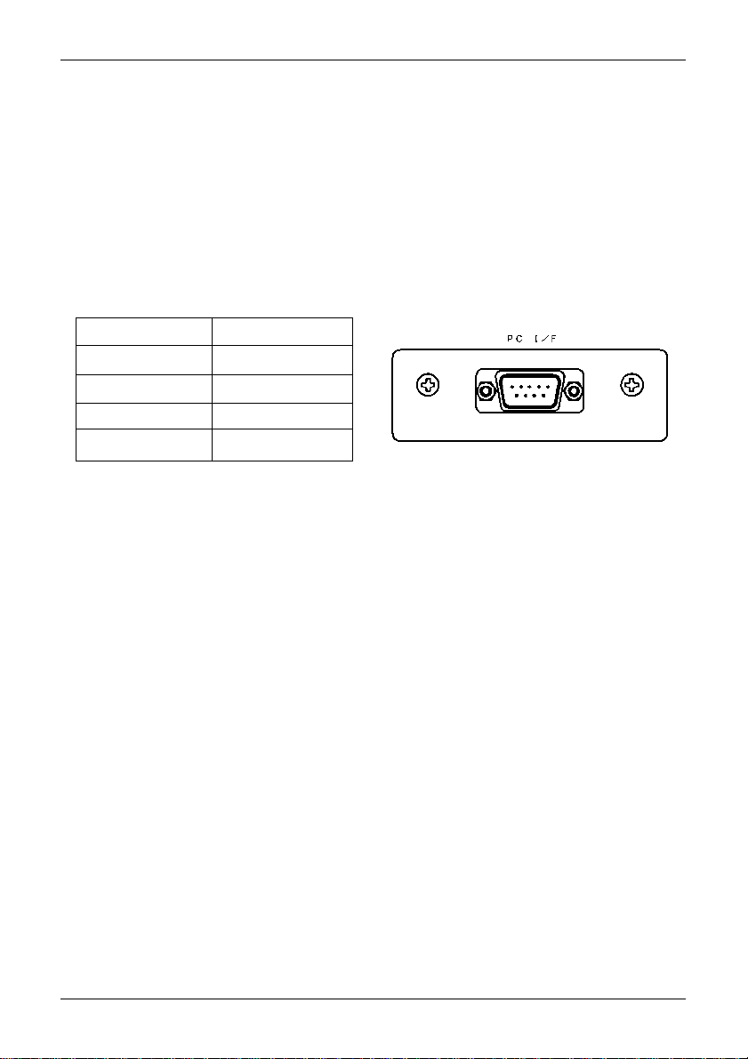
Section 8, 8-1, 8-2
8. SDU5600 Command List
The SDU5600 can be operated via PC using the RS232 port.
8-1 Communication parameter and connecting lead
The SDU5600 and a PC should be connected using a straight cable between
the [PC I/F] socket and the serial port of the PC. The SDU5600 port is MALE,
so the PC lead must have a female connector or a gender changer will have to
be employed.
Communications parameters of the SDU5600
Baud rate 9600bps
Data length 8 bit
Parity None
Stop bit 2 bit
Flow control RTS/CTS
8-2 Delimiter
A brief description of delimeter and response format is given here.
Delimiter
Each command from the PC to SDU5600 is defined by:
<CR> 0x0d in 16-bit form
or
<CR><LF> 0x0d,0x0a in hexadecimal format
Note: <LF> will be ignored
Response when the command has been correct:
<SP><CR><LF> 0x20,0x0d,0x0a in hexadecimal format
Response when the command has been incorrect:
?<CR><LF> 0x3f,0x0d,0x0a in hexadecimal format
Response to the read command:
Following the output of the parameter, the correct response should read
<SP><CR><LF> 0x20,0x0d,0x0a in hexadecimal format
39
Page 40

Section 8-3, 8-4
8-3 Basic format of the command
Each command to be sent to the SDU5600 consists of 4 letters (upper case) in
ASCII code with appropriate parameters followed by <CR><LF>.
Each letter represents the following:
(1) First letter Either W for write or R for read
(2) Second letter Line of command such as S for
spectrum analysis, V for visual
set-up, U for user interface and
I for information
(3 & 4) Third and Fourth letter Categories of each line of command
8-4 RS232 command list
Commands are divided into four categories:
S = Spectrum analysis
V = Visual command
U = User Interface
I = Information
Microsoft Windows® Hyper T erminal® may be used to control the SDU5600 or you may write your
own software.
An example of command format is given here:
RSCF<CR> Response: SCF79.5<SP><CR><LF>
In this example, the centre frequency is read.
Command = Read
Category = Spectrum analysis
Type of command (abbreviation) = CF
Parameter (variable) = Not used in this example
Example of input = RSCF<CR> Response from SDU5600 = SCF79.5<SP><CR><LF>
A correct WRITE command results in the action being carried out and <CR><CR><LF> being
returned. An incorrect command results in a question mark “?” followed by <CR><LF> being
returned.
40
Page 41

Section 8-4
Spectrum analysis
Command : WSCF Function : SET CENTER FREQUENCY Command category: WRITE
Parameter : Min- Max (in MHz)
Example : WSCF79.5<CR><LF> Response: if correct: <SP><CR><LF>
Remarks: Frequency entry for out of receive range will be respond by ?<CR><LF>, and the
command will be ignored.
Command : RSCF Function : READ CENTER FREQUENCY Command category: READ
Parameter : N/A
Example : RSC<CR><LF> Response: SCF79.5<SP><CR><LF>
Remarks: Frequency is displayed in MHz.
Command : WSSP Function : SET SPAN FREQUENCY Command category: WRITE
Parameter : 0.16 ~ 10 (MHz)
Example : WSSP0.62<CR><LF> Response: if correct: <SP><CR><LF>
Remarks: Data entry for out of range will be respond by ?<CR><LF>, and the command will be
ignored.
Command : RSSP Function : READ SP AN FREQUENCY Command category: READ
Parameter : N/A
Example : RSSP<CR><LF> Response: SSP0.62<SP><CR><LF>
Remarks: Frequency is displayed in MHz.
Command : WSBW Function : SET RBW Command category: WRITE
Parameter : 1 ~ 4
Example : WSBW1<CR><LF> Response: if correct: <SP><CR><LF>
Remarks: Parameter vs. RBW is as follows: 1 = 4 KHz, 2 = 32 KHz, 3 = 64 KHz, 4 = 128 KHz
Data entry for out of range will be respond by ?<CR><LF>, and the command will be ignored.
Command : RSBW Function : READ RBW Command category: READ
Parameter : N/A
Example : RSBW<CR><LF> Response: SBW4<SP><CR><LF>
Remarks: Parameter vs. RBW is as follows: 1 = 4 KHz, 2 = 32 KHz, 3 = 64 KHz, 4 = 128 KHz.
Command : WSGN Function : SET AMPLITUDE Command category: WRITE
Parameter : -30 ~ 0
Example : WSGN-30<CR><LF> Response: if correct: <SP><CR><LF>
Remarks: Amplitude is set in 10 incremental. Data entry for out of range will be respond by
?<CR><LF>, and the command will be ignored.
Command : WSCM Function : SET CURSOR Command category: WRITE
Parameter : 1 ~ 3
Example : WSCM3<CR><LF> Response: if correct: <SP><CR><LF>
Remarks: Parameter : 1 = MARKER, 2 = PEAK, 3 = C-PEAK To use this command, you need to set
the trigger level by using the WSTL command. Data entry for out of range will be respond by
?<CR><LF>, and the command will be ignored.
Command : RSCM Function : READ CURSOR Command category: READ
Parameter : N/A
Example : RSCM<CR><LF> Response: SCM1<SP><CR><LF>
Remarks: Parameter : 1 = MARKER, 2 = PEAK, 3 = C-PEAK
if incorrect: ?<CR><LF>
if incorrect: ?<CR><LF>
if incorrect: ?<CR><LF>
if incorrect: ?<CR><LF>
if incorrect: ?<CR><LF>
41
Page 42

Section 8-4
Command : WSTL Function : SET PEAK TRIGGER LEVEL Command category: WRITE
Parameter : -90 ~ 0
Example : WSTL-80<CR><LF> Response: if correct: <SP><CR><LF>
Remarks: Data entry for out of range will be respond by ?<CR><LF>, and the command will be
ignored.
Command : RSTL Function : READ PEAK TRIGGER LEVEL Command category: READ
Parameter : N/A
Example : RSTL<CR><LF> Response: STL-80<SP><CR><LF>
Remarks: Read the trigger level in the Peak mode.
Command : WSDM Function : SET DATA MODE Command category: WRITE
Parameter : 1 ~ 4
Example : WSDM2<CR><LF> Response: if correct: <SP><CR><LF>
Remarks: Parameter: 1 = NORMAL, 2 = AVR, 3 = MAX, 4 = MED If AVR or MED is selected, you
need to set the WSME command before executing the command. Data entry for out of range will
respond by ?<CR><LF>, and the command will be ignored.
Command : RSDM Function : READ DA T A MODE Command category: READ
Parameter : N/A
Example : RSDM<CR><LF> Response: SDM3<SP><CR><LF>
Remarks: Parameter: 1 = NORMAL, 2 = AVR, 3 = MAX, 4 = MED
Command : WSAV Function : SET AVR SAMPLING Command category: WRITE
Parameter : 2 ~ 31
Example : WSAV10<CR><LF> Response: if correct: <SP><CR><LF>
Remarks: Set AVR sampling and set the DATA mode to AVR. Data entry for out of range will respond
by ?<CR><LF>, and the command will be ignored.
Command : RSAV Function : READ AVR SAMPLING Command category: READ
Parameter : N/A
Example : RSAV<CR><LF> Response: SA V10<SP><CR><LF>
Command : WSME Function : SET MED SAMPLING Command category: WRITE
Parameter : 2 ~ 4
Example : WSME4<CR><LF> Response: if correct: <SP><CR><LF>
Remarks: Set MED sampling and set the DATA mode to MED. Data entry for out of range will
respond by ?<CR><LF>, and the command will be ignored.
Command : RSME Function : READ MED SAMPLING Command category: READ
Parameter : N/A
Example : RSMED<CR><LF> Response: SMED4<SP><CR><LF>
if incorrect: ?<CR><LF>
if incorrect: ?<CR><LF>
if incorrect: ?<CR><LF>
if incorrect: ?<CR><LF>
42
Page 43

Section 8-4
Visual command
Command : WVPM Function : SET PLOT MODE Command category: WRITE
Parameter : 1 ~ 2
Example : WVPM2<CR><LF> Response: if correct: <SP><CR><LF>
Remarks: Parameter: 1 = PAINT, 2 = OUTLINE Data entry for out of range will be respond by
?<CR><LF>, and the command will be ignored.
Command : RVPM Function : READ PLOT MODE Command category: READ
Parameter : N/A
Example : RVPM<CR><LF> Response: VPM1<SP><CR><LF>
Remarks: Parameter: 1 = PAINT, 2 = OUTLINE
Command : WVDD Function : SET F-DIR Command category: WRITE
Parameter : 1 ~ 2
Example : WVDD2<CR><LF> Response: if correct: <SP><CR><LF>
Remarks: Parameter: 1 = NORMAL, 2 = REVERSE Data entry for out of range will be respond by
?<CR><LF>, and the command will be ignored. This command is available only when the receiver is
selected either Other(10M) or Other (45M).
Command : RVDD Function : READ F-DIR Command category: READ
Parameter : N/A
Example : RVDD<CR><LF> Response: VDD1<SP><CR><LF>
Remarks: Parameter: 1 = NORMAL, 2 = REVERSE
Command : WVWF Function : SET WATERFALL FUNCTION Command category: WRITE
Parameter : 1 ~ 2
Example : WVWF2<CR><LF> Response: if correct: <SP><CR><LF>
Remarks: Parameter: 1 = NORMAL, 2 = WATERFALL Data entry for out of range will be respond by
?<CR><LF>, and the command will be ignored
Command : RVWF Function : READ WATERFALL FUNCTION Command category: READ
Parameter : N/A
Example : RVWF<CR><LF> Response: VWF2<SP><CR><LF>
Remarks: Parameter: 1 = NORMAL, 2 = WATERFALL
Command : RVIM Function : READ VISUAL IMAGE Command category: READ
Parameter : N/A
Example : RVIM<CR><LF> Response:
Remarks: Due to the huge volume of image data, while this command is executed the
communication speed will be changed to 115200bps. After data read is completed, the data speed
will return to 9600 bps. A specific example of the resonse cannot be presented here due to its nature.
if incorrect: ?<CR><LF>
if incorrect: ?<CR><LF>
if incorrect: ?<CR><LF>
see remarks
43
Page 44

Section 8-4
User interface
Command : WUMD Function : SET RECEIVER MODE Command category: WRITE
Parameter : 1 ~ 15
Example : WUMD1<CR><LF> Response: if correct: <SP><CR><LF>
Remarks: Parameter: 1 = WFM, 2 = NFM, 3 = SFM, 4 = WAM, 5 = AM, 6 = NAM, 7 = LSB,
8 = USB, 9 = CW, 10 = AUTO, 11 = AMW, 12 = FM, 13 = FMN, 14 AMN, 15 = CWN
Data entry for out of range or any mode that is not supported by the associated receiver will respond
by ?<CR><LF>, and the command will be ignored
Command : RUMD Function : READ RECEIVER MODE Command category: READ
Parameter : N/A
Example : RUMD<CR><LF> Response: UMD1<SP><CR><LF>
Remarks: Parameter: 1 = WFM, 2 = NFM, 3 = SFM, 4 = WAM, 5 = AM, 6 = NAM, 7 = LSB,
8 = USB, 9 = CW, 10 = AUTO, 11 = AMW, 12 = FM, 13 = FMN, 14 AMN, 15 = CWN
Command : WUAT Function : SET ATT Command category: WRITE
Parameter : 1 ~ 2
Example : WUAT2<CR><LF> Response: if correct: <SP><CR><LF>
Remarks: Parameter: 1 = ON, 2 = OFF Data entry for out of range or the attenuator function is not
supported by the associated receiver, the SDU5600 will respond by ?<CR><LF>, and the command
will be ignored
Command : RUAT Function : READ A TT MODE Command category: READ
Parameter : N/A
Example : RUAT<CR><LF> Response: UAT2<SP><CR><LF>
Remarks: Parameter: 1 = ON, 2 = OFF
Command : WUST Function : SET STEP FREQ. Command category: WRITE
Parameter : Size in KHz
Example : WUST12.5<CR><LF> Response: if correct: <SP><CR><LF>
Remarks: Data entry for out of range or if the input freq. step is not supported by the associated
receiver, the SDU5600 will respond by ?<CR><LF>, and the command will be ignored
Command : RUST Function : READ STEP FREQ. Command category: READ
Parameter : N/A
Example : RUST<CR><LF> Response: UST12.5<SP><CR><LF>
Remarks: Size in KHz
Command : WURX Function : SELECT RECEIVER Command category: WRITE
Parameter : 1 ~ 10
Example : WURX3<CR><LF> Response: if correct: <SP><CR><LF>
Remarks: Parameter: 1 = Other (10M), 2 = Other (45M), 3 = AR5000, 4 = AR3000A,
5 = AR8600 (10M), 6 = AR8600 (45M), 7 = AR8200, 8 = AR-ONE, 9 = IC-R8500, 10 = IC-R7100,
11 = RFU5600 Data entry for out of range will respond by ?<CR><LF>, and the command will be
ignored.
Command : RURX Function : READ RECEIVER TYPE Command category: READ
Parameter : N/A
Example : RURX<CR><LF> Response: URX3<SP><CR><LF>
Remarks: Parameter: 1 = Other (10M), 2 = Other (45M), 3 = AR5000, 4 = AR3000A,
5 = AR8600 (10M), 6 = AR8600 (45M), 7 = AR8200, 8 = AR-ONE, 9 = IC-R8500, 10 = IC-R7100,
11 = RFU5600
if incorrect: ?<CR><LF>
if incorrect: ?<CR><LF>
if incorrect: ?<CR><LF>
if incorrect: ?<CR><LF>
44
Page 45

Section 8-4
Command : WUMC Function : SET MARKER FREQ. AS RECEIVE FREQ.
Parameter : N/A
Example : WUMC<CR><LF> Response: if correct: <SP><CR><LF>
if incorrect: ?<CR><LF>
Remarks: This command is not available for the Other (10M) or Other (45M) receiver.
Command : WUDS Function : MOVE MARKER POSITION Command category: WRITE
Parameter : 1 ~ 2
Example : WUDS2<CR><LF> Response: if correct: <SP><CR><LF>
if incorrect: ?<CR><LF>
Remarks: Parameter: 1 = 1 step left, 2 = 1 step right Data entry for out of range will respond by
?<CR><LF>, and the command will be ignored.
Command : WUOM Function : SET MONITOR MODE Command category: WRITE
Parameter : 1 ~ 3
Example : WUOM1<CR><LF> Response: if correct: <SP><CR><LF>
if incorrect: ?<CR><LF>
Remarks: Parameter: 1 = Spectrum analyzer mode, 2 = StepReso. mode, 3 = Channel mode
Data entry for out of range will respond by ?<CR><LF>, and the command will be ignored.
Command : RUOM Function : READ MONITOR MODE Command category: READ
Parameter : N/A
Example : RUOM<CR><LF> Response: UOM1<SP><CR><LF>
Remarks: Parameter: 1 = Spectrum analyzer mode, 2 = StepReso. mode, 3 = Channel mode
Command : WUCS Function : PROGRAM CHANNEL MODE Command category: WRITE
Parameter : 3 parameter entry
Example : WUOS 79.5 10 81.1<CR><LF> Response: if correct: <SP><CR><LF>
Remarks: Enter START freq. and END freq. in MHz, and STEP freq. in KHz. Enter the <SP>
(Space) between each parameter. Data entry for out of range will respond by ?<CR><LF>, and the
command will be ignored.
Command : RUCS Function : READ CHANNEL MODE Command category: READ
Parameter : N/A
Example : RUCS<CR><LF> Response: USCS 79.5 10 81.1<SP><CR><LF>
Remarks: Respond START freq. and END freq. in MHz, and STEP freq. in KHz. There is space
between each parameter.
Command : WUBP Function : SET BEEP ON/OFF Command category: WRITE
Parameter : 1 ~ 2
Example : WUBP1<CR><LF> Response: if correct: <SP><CR><LF>
if incorrect: ?<CR><LF>
Remarks: Parameter: 1 = BEEP ON, 2 = BEEP OFF
Command : RUBP Function : READ BEEP ON/OFF Command category: READ
Parameter : N/A
Example : RUBP<CR><LF> Response: UBP1<SP><CR><LF>
Remarks: Parameter: 1 = BEEP ON, 2 = BEEP OFF
Command category: WRITE
if incorrect: ?<CR><LF>
45
Page 46

Section 8-4
Command : WUBE Function : BEEP SETTING Command category: WRITE
Parameter : 1 ~ 7
Example : WUBE6<CR><LF> Response: if correct: <SP><CR><LF>
Remarks: Parameter: 1 = Emit “click” when key is pressed.
Data entry for out of range will respond by ?<CR><LF>, and the command will be ignored.
if incorrect: ?<CR><LF>
2 = Emit “click” when key entry is ignored.
3 = Beep when correct entry is made.
4 = Beep when entry data is out of range.
5 = Beep when key entry is cancelled.
6 = Beep when On/Off parameter is set to ON.
7 = Beep when On/Off parameter is set to OFF .
General information
The following commands are used only during production of the SDU5600 to assist testing, and
therefore, the commands are given for completeness only.
Command : RVIM Function : READ VISUAL IMAGE Command category: READ
Parameter : N/A
Example : RVIM<CR><LF> Response:
Remarks: When this command is sent to the SDU5600, it will respond as follows:
1 Respond to the command by sending <SP><CR><LF> to PC.
2. Wait for approximately 400 mS.
3. Change baud rate to 115200bps automatically .
4. Output VIM (0x56, 0x49, 0x4d in hexadecimal).
5. Output 1 dot ( = 1 byte) of screen image data in 2 characters (in hexadecimal).
(Example) 0x4a data = 1A (2 byte) 0x31, 0x41 (in hexadecimal) 356 x 236 dot
(= 168032 characters)
6. Output X (0x58 in hexadecimal).
7. Wait for approximately 100 mS.
8. Return baud rate to 9600 bps again.
9. Output OK response <SP><CR><LF>.
Command : RIGD Function : GRAPHIC DOWNLOAD Command category: READ
Parameter : N/A
Example : RIGD<CR><LF> Response:
Remarks: When this command is sent to the SDU5600, it will respond as follows producing a level
whic corresponds to each frequency across the sceen.
(Example):
========== Start from here ============
IGD<SP>CR><LF>
/<SP><CR><LF>
F5.70000, L-90<SP><CR><LF>
F5.73125, L-90<SP><CR><LF>
(Some lines omitted)
F7.73125, L-86<SP><CR><LF>
F7.76250, L-86<SP><CR><LF>
(Some lines omitted)
F15.66875, L-90<SP><CR><LF>
F15.70000, L-90<SP><CR><LF>
/<SP><CR><LF>
========== End =====================
see remarks
see remarks
46
Page 47

Section 8-4
Produces a ‘pair’ of data values comprising of frequency and its level at MHz order which is defined
(sandwiched) by / /. In reality, there may be a discrepancy of +/- 1dBm between the value of the
marker on the LCD and the level of the same marker which is calculated by this command.
Command : RICD Function : CURSOR DOWNLOAD Command category: READ
Parameter : N/A
Example : RICD<CR><LF> Response:
Remarks: Read output level of the cursor frequency.
(Example):
========== Start from here ============
f10.70000, l-78<SP>CR><LF>
========== End =====================
Note: Use small F or L (not a capital) for this command. This produces the information in one line
unlike the download plot information. In reality, there may be a discrepancy of +/- 1dBm between the
value of the marker on the LCD and the level of the same marker which is calculated by this
command.
Command : RIFD Function : HIGH SPEED DATA DOWNLOAD Command category: READ
Parameter : N/A
Example : RIFD<CR><LF> Response:
Remarks: Read output level on each frequency on the screen as 1 byte data.
(Example):
========== Start from here ============
IFD<SP><CR><LF>
<SP>CR><LF>
(Some lines omitted, these are level data area.) #%$-+#!
(Some lines omitted) <SP>
<SP>
<SP><CR><LF>
========== End =====================
The level data per frequency will be presented in ASCII code which has been obtained by calculation
of the label, 100 + 0x20.
Note: Use small F or L (not a capital) for this command. In reality, there may be a discrepancy of +/1dBm between the value of the marker on the LCD and the level of the same marker which is
calculated by this command.
Command : RIVE Function : READ FIRMWARE VERSION Command category: READ
Parameter : N/A
Example : RIVE<CR><LF> Response:
Remarks: (Example):
========== Start from here ============
IVE<SP>Ver .<SP>007<SP>307C<SP><SP><CR><LF>
========== End =====================
Produces the version information followed by IVE<SP>
see remarks
see remarks
see remarks
47
Page 48

Section 8-4
Notes for programmers
Generally speaking the screen dump is preferable if graphic info (data) is
wanted. On the other hand the array of frequency / level can better serve if
numerical data is demanded. The array of frequency / level is faster in transfer
time from the SDU5600 to the PC.
The SDU5600 accepts commands either from the PC or from its own front
panel on a first come first serve basis. For example the PC has sent data to
switch the SPAN bandwidth to 10MHz followed by data from the front panel
setting the same parameter to 5MHz. The SDU5600 will perform the change to
10MHz then to 5MHz.
AOR is considering commissioning a PC control package for the SDU5600,
keep an eye on the AOR web site for possible information:
www.aorja.com
www.aoruk.com
www.aorusa.com
48
Page 49

9 Specification
Input frequency 10.7MHz / 45.05MHz selectable
Maximum frequency span 10MHz
RBW 4kHz, 32kHz, 64kHz, 128kHz
Dynamic range 60dB
Input impedance 50 OHM via BNC socket
Display screen 5 inch (127mm) TFT Colour LCD
Communications RS232C (2 ports)
Power requirement 12DC @ 0.9A nominal, negative ground
Operation 26 keys & main dial
Operating temperature 0 to 50 degrees Celsius
Dimensions 220(W) x 120(H) x 195(D) mm
Weight 2.3kg
Specifications subject to change without notice.
All trade marks acknowledged. E&OE.
49
Page 50

Notes:
50
Page 51

51
Page 52

52
®
AOR Ltd
2-6-4 Misuji, Taito-ku, Tokyo 111, Japan.
Tel: +81 3 3865 1695 Fax: +81 3 3865 1697
post@aorja.com www.aorja.com
AOR (UK) Ltd
4E East Mill, Bridgefoot, Belper, Derbys DE56 2UA, England
T el: +44 1773 880788 Fax: +44 1773 880780
info@aoruk.com www.aoruk.com
AOR USA INC.,
20655 S. Western Ave., Suite 1 12, Torrance, CA 90501 USA
T el: 310 787 8615 Fax: 310 787 8619
info@aorusa.com www.aorusa.com
0104
 Loading...