

Page 1

®
ARD9900
FAST RADIO MODEM
Multi-Mode and Digital Voice Interface
Operating manual
AOR, LTD.
Page 2

1
Thank you for purchasing the AOR ARD9900 Multimode and Digital Voice Interface.
The ARD9900 is designed to convert your HF radio equipment to a multi mode and digital voice
capable radio without performing any modifications to your transceiver.
Please read through this instruction manual and familiarize yourself with the operation of the
ARD9900.
We suggest you keep this instruction manual for future reference.
We believe the ARD9900 will become a powerful tool to your communication capabilities.
AOR, LTD.
Page 3

2
Features:
Digital voice communications using existing analog 2 way radios with encryption.
The ARD9900 uses the same audio frequencies (300 Hz ~ 2500 Hz) as microphone
audio to modulate the voice signal. This allows you to use an analog radio as a digital
voice transceiver.
Digital voice communications in the Single Side Band (SSB) mode.
The automatic frequency clarifier function adjusts frequency drift automatically in the
SSB mode. (Approximately up to +/- 125 Hz).
Utilizes the ODFM (Multi Carrier Modulation) circuit that is effective against Multi-path or
Selective Fading.
Automatic digital receive
Automatic voice signal detector recognizes the received signal as analog or digital,
automatically switching to the appropriate mode.
Digital Slow Scan TV (SSTV)
Built-in video-capture function (NTSC or PAL depending on version)
Compresses the signal into our original adaptive JPEG format. Send and receive
images in the Digital mode. Built-in video output connector allows viewing the picture on
an external monitor.
Built–in high grade Vocoder (AMBE)
Utilizing high grade digital voice compression; delivers quality digital voice
communications.
Built-in FEC error correction
A powerful error correction circuit delivers stable and reliable communications.
Data communications on the HF band
Data communication is possible on the HF (High frequency) bands at no extra cost.
(Speed may be limited by regulations in certain jurisdictions.)
Small and compact unit. Easy to operate.
Simply connect the ARD9900 to the microphone jack and the speaker out jack. No
complicated or risky radio modifications are necessary.
Utilizes a uniquely designed high performance DSP (Digital Signal Processor) engine
Battery operation for field use.
Page 4

3
Information to the Digital Device user
This equipment uses and can generate radio frequency energy and, if not installed and
used in accordance with the instructions, may cause harmful interference to radio
communications. However, there is no guarantee that the interference will not occur in a
particular installation. If this equipment does cause harmful interference to radio or
television reception, which can be determined by turning the equipment off and on, the
user is encouraged to try to correct the interference by one or more of the following
measures:
Reorient or relocate the receiving antenna.
Increase the separation between the equipment and receiver.
Connect the equipment to an outlet on a circuit different from that to which the
receiver is connected.
Consult the dealer for technical assistance.
Precautions
To prevent fire, personal injury, or unit damage, please observe the following precautions:
Do not attempt to adjust this unit unless instructed to do so by this manual.
Do not expose the unit to direct sunlight or place the unit close to heating
appliances.
Do not place the unit in excessively dusty, humid, wet areas.
We are not responsible for any damages to the radio equipment due to improper settings
or interface.
We are not responsible for any loss of communications due to an unexpected change of
propagation or operating environment.
Page 5

4
Table of Contents
Page
Supplied Accessories ------------------------------------------------------------------------------------ 5
Controls and functions ---------------------------------------------------------------------------------- 5
Front Panel -------------------------------------------------------------------------------------------- 5
Rear Panel -------------------------------------------------------------------------------------------- 8
Top Panel ----------------------------------------------------------------------------------------------10
Internal View ------------------------------------------------------------------------------------------10
Bottom View -------------------------------------------------------------------------------------------11
Interfacing the ARD9900 -------------------------------------------------------------------------------12
Connection to a Radio ----------------------------------------------------------------------------- 12
Connection to a Microphone --------------------------------------------------------------------12
Connection to a PC ------------------------------------------------------------------------------- 13
Connection to a Power supply ------------------------------------------------------------------ 13
Connection to an External speaker ------------------------------------------------------------ 13
Level Adjustment ----------------------------------------------------------------------------------------14
Microphone level ------------------------------------------------------------------------------------14
Radio Input level -------------------------------------------------------------------------------- 14
Code Setting ---------------------------------------------------------------------------------------------- 15
Master Key Code Setting -------------------------------------------------------------------------15
User ID Code Setting ------------------------------------------------------------------------------15
Air Key Code Setting ------------------------------------------------------------------------------16
Channel Switch Setting ---------------------------------------------------------------------------16
Operations ------------------------------------------------------------------------------------------------18
Voice Communication -----------------------------------------------------------------------------18
Digital Voice Communication ----------------------------------------------------------------18
Analog Voice Communication ---------------------------------------------------------------18
Force Receive -----------------------------------------------------------------------------------18
Data Communication ----------------------------------------------------------------------------- 18
Receive -------------------------------------------------------------------------------------------19
Transmit ------------------------------------------------------------------------------------------ 19
Digital Image Communication ------------------------------------------------------------------- 19
Receive -------------------------------------------------------------------------------------------19
Transmit ------------------------------------------------------------------------------------------20
Specifications --------------------------------------------------------------------------------------------21
Type of Communications and their respective features --------------------------------------22
Communication Selection Guidance --------------------------------------------------------------23
Communication Mode Setting -----------------------------------------------------------------------24
Detailed functions of communication mode ------------------------------------------------------25
Control Commands -------------------------------------------------------------------------------------28
Interfacing to a PC -----------------------------------------------------------------------------28
Terminal Settings -------------------------------------------------------------------------------28
Command format -------------------------------------------------------------------------------29
Entering the System Management Screen ----------------------------------------------29
Operator’s Command List --------------------------------------------------------------------30
Operator’s Command Details-----------------------------------------------------------------31
Command List for the System Manager --------------------------------------------------33
Command Details of the System Manager ----------------------------------------------34
Page 6

5
Supplied Accessories
The following items are provided in the box:
Accessory Quantity
----------------------------------------------------------------
Microphone 1
PC interface cable 1
Speaker Cable 1
DC Power cable 1
Microphone Connector 1
Instruction manual 1
Controls and functions
Front Panel
DRA
009
9
|
○
PPPPOOOOWWWWEEEERRRR
BBBBUUUUSSSS
SSSSPPPP CCCCHHHHAAAANNNNTTTTXXXX SSSSTTTTAAAA MMMMOOOODDDDEEEE
a
c d
b
e
a. Power on/off switch
b. TX switch
There are two (2) functions with this switch.
1. Digital Image Communication mode
Set the mode switch to [10101] (digital mode). Press this switch to capture
and send an image.
Note: When the Video Through Function is activated (AVT command is ON),
pressing this switch will enable output of the video signal connected to the Video
Input to also be sent to the video output port, so that you can monitor the
transmitted video image.
Press this switch again to capture and send the image through the radio
equipment. When the Video Through Function is de-activated (AVT command is
OFF), pressing this switch will automatically capture the video image and then
transmit it through the radio equipment.
(Refer to: Operation -- Digital Image Communication at page 18 for details.)
MMF EDOOIDARTSA
11110000111100001111
9
7
A
6
B
5
MaxMin
f
C
4
D
3
E
2
F
0
1
OOOOVVVVEEEERRRR
h
g
MMMMIIIICCCC
i
j
Page 7

6
2. Digital Voice Communication mode (non encryption or fixed scramble code
mode)
Set the mode switch to [~] (analog mode). Press and hold this switch to
force the ARD9900 to decode digital voice signals.
Caution: Frequency tolerance for both parties must be in the range of +/-125 Hz.
(Refer to: Operations -- Digital Voice Communication force receive at page 17
for details.)
c. BUS LED (Busy LED)
Steady red
The unit is in the transmit mode
Flashing red
Flashes red while the header information is being sent, when in the digital
communication mode. (Approximately one second).
Green
The unit is in the receive mode
Not lit
The unit is in the standby receive mode or in the analog voice receive
mode.
d. STA LED (Status LED)
In the data communication mode, lit while unsent data is in the memory. It
displays orange when the Video Through Function is activated (Digital
Image Communication mode). When the Video Through Function is deactivated (AVT command is OFF), this LED will not be lit.
e. Speaker volume adjustment
Adjustment for the internal speaker output level (or the external speaker
output level when it is connected.)
f. MODE LED (Operation Mode LED)
Indicates the current operation mode:
Lit in green ----- Digital Voice mode
Lit in red ----- Analog Voice mode
Lit in orange ----- Data Communication mode
Not lit ----- Digital Image Communication mode
g. CHANNEL switch
Select preloaded encryption code.
(Refer to: Channel Switch Setting at page 15 for details.)
h. Overload indicator
Lit when the microphone input is overloaded (too high).
A proper microphone input level will cause the LED to flash from time to
time when speaking into the microphone at a normal level.
The microphone level can be adjusted with the microphone level controller.
(Refer to: Level Adjustment at page 13 for details.)
Page 8

7
i. Mode switch
Select the Digital voice mode [10101] or the Analog voice mode [~].
When the Analog voice mode [~] is selected, ordinary analog voice
communications will be made. In the receive mode, however, the ARD9900
will automatically detect the mode of the incoming signal and decode signals
accordingly. The LED indicates the respective operation mode.
j. Microphone connector
Connect the supplied microphone to this connector.
Below are the pin assignments of the connector.
1. Speaker output -- Monitor output signal is present at this pin.
2. BIAS -- Power source for an electret condenser type of
microphone. 5V DC through 2.2KΩ resistor.
3. GND -- Chassis ground
4. TX -- Grounding this pin will enable the transmit
mode.
(Same operation as the TX switch on the front
panel.)
5. D/A -- Grounding this pin will force the unit to the
digital voice communication mode. When this pin is
left open, the operation mode will be set by the mode
switch on the front panel.
6. MIC PTT -- PTT (Push To Talk) input.
7. MIC GND -- Microphone ground signal
8. MIC IN -- Microphone signal input
Rear Panel
k. Communication Connector (mini DIN 8 pin) for PC (RS-232C)
Pin Number Signal Signal Direction
1 TX ARD9900 PC
2 DTR ARD9900 PC
3 DSR ARD9900 PC
4 GND GND
5 RX ARD9900 PC
6 RTS ARD9900 PC
7 CTS ARD9900 PC
8 NC No Connection
Shell FG Frame ground
AOR,LTD.
k
VIDEO
IN OUT
l
m n
RADIO
OUT
SP
IN
o
p q r
+-
DC IN
Page 9

8
Baud Rate: 9600
Data bit: 8
Start bit: 1
Stop bit: 1
Parity: None
Synchronization: Asynchronous
Flow control: Hardware
l. VIDEO - IN connector (75Ω) (RCA type connector)
Connect a video signal source such as a digital camera.
m. VIDEO – OUT connector (75Ω) (RCA type connector)
Connect a video monitor to this connector to monitor a received image or a
picture to be sent.
n. RADIO Connector
Using the supplied 8 pin connector, connect the ARD9900 to your radio equipment.
You will need to wire a cable according to the microphone connector specifications
of your radio.
Below are the pin assignments of the connector on the ARD9900.
Pin number Signal Details
1 MIC GND Microphone ground
2 MIC OUT Microphone Output
3 PTT PTT (Push To Talk) output
4 GND PTT ground
5 NC No connection
6 NC No connection
7 GND Ground
8 NC No connection
(Caution: MIC GND and GND must not be connected together in the ARD9900
connector, or RF feedback will result.
o. SP IN Connector (3.5 mm mono jack)
Connect to the radio equipment’s external speaker jack.
(Input level: 0.5 V – 5 V p-p)
p. SP OUT Connector (3.5 mm mono jack)
Connect an external speaker to this jack to disable internal speaker.
q. DC IN Connector (EIAJ Type 4)
Connect to a regulated power supply. (10.7 ~ 16.0 V DC, Center pin – positive)
For lower voltage battery operation, set the internal jumper terminal for battery
operation, and then connect external batteries .
Page 10

9
r. FG
Frame ground
Top Panel
Internal View
(PCB design subject
to changes.)
t.
Factory setting jumper
Must be set between 2-3. (Do not change this setting at any time.)
v. Battery operation selector
Place the jumper between 1 – 2 (NOR) for normal operation.
If you have changed the internal jumper for low-voltage battery operation,
(Caution: If you have changed the internal jumper for low-voltage battery operation,
battery voltage must be within the range of 5.6 ~6.5 VDC.
DO NOT apply 12.0V or severe damage will result, and the warranty will be
void!)
Note: No low battery voltage detector is built-in the ARD9900.
s
Internal Speaker
Change it between 2-3 (BATT) for battery operation.
battery voltage must be within the range of 5.6 ~6.5 VDC.
DO NOT apply 12.0V or severe damage will result, and the warranty will be
void!
(Note: No low battery voltage detector is built-in the ARD9900.)
Page 11

10
w. Internal speaker setting
Jumper setting
1 – 2 Activates internal speaker (default)
2 – 3 Disable internal speaker
Speaker output is also available from the pin #1 of the
microphone connector.
(Note: The SP OUT (external speaker output) has priority regardless
of the above jumper setting.)
x. Output level setting
Jumper setting
1 – 2 Normal level (default) (LOW)
2 – 3 High level (HIGH)
In case the microphone output level is too low to drive your radio equipment,
place the jumper to the 2-3 position.
(Refer to: Microphone Level Adjustment at page 13 for details.)
Bottom View
y. Microphone output (Radio Input) level
(Refer to: Setting - Level Adjustment for Radio Input at 19 for details.)
y
Page 12

11
Interfacing the ARD9900
Connection to a Radio
Before using your ARD9900, you will first need to wire the cable between your radio
equipment and the ARD9900.
For your convenience, an 8-pin of a microphone connector for the ARD9900 is included.
You will need to prepare, however, your own microphone connector for your radio
equipment.
Below are the pin assignments of the 8-pin RADIO connector on the rear panel of the
ARD9900.
Pin number Signal Details
1 MIC GND Microphone ground
2 MIC OUT Microphone output
3 PTT (H) PTT (Push To Talk) output
4 PTT (L) PTT (Push To Talk) ground
5 NC No connection
6 NC No connection
7 GND Ground
8 NC No connection
ARD9900
・RADIO Connector
1 MIC GND
2 MIC OUT
3 PTT(H)
4 PTT(L)
5 NC
6 NC
7 GND
8 NC
Shell
RADIO EQUIPMENT
MIC GND
MIC IN
PTT IN
PTT GND
GND
Shell
EXTERNAL SPEAKER OUT
GND
・SP IN Connector
Signal
GND
(Note: MIC GND and GND must not be connected together in the ARD9900 connector,
or RF feedback will result.)
Connection to a Microphone
A speaker microphone is included with your ARD9900. However, if you wish to use
your own microphone with the ARD9900, you may do so by wiring your microphone to
correlate with the input jack of the ARD9900. Below are the pin assignments of the
Microphone connector of the ARD9900.
1. Speaker output
Monitor output signal is present at this pin when the internal speaker
Jumper is set to 2 – 3.
2. BIAS
Power source for an electric condenser type of microphone. 5V DC
through 2.2KΩ resistor.
3. GND
Chassis ground
Page 13

12
4. TX
Taking this pin to the ground will enable to transmit.
(Same operation as the TX switch on the front panel.)
5. D/A
Taking this pin to the ground will force the ARD9900 to the Digital voice
communication mode. When this pin is left open, the operation mode will
be set by the mode switch on the front panel.
6. PTT
PTT (Push To Talk) input.
7. MIC GND
Microphone ground signal
8. MIC IN
Microphone signal input
Connection to a PC
A PC interface cable is included with the ARD9900.
Parameter settings can be made by using terminal software.
(Refer to: Control Commands at page 27 for details.)
Connection to a Power Supply
To operate your ARD9900, use a regulated power supply.
The operating voltage must be in the range of 10.7 ~ 16.0 V DC (approximately
200mA).
A DC power cable is also included with the ARD9900.
Color Polarity
========================
RED Positive (+)
BLACK Negative ( - )
If you have changed the internal jumper for low-voltage battery operation, supplied
voltage must be in the range of 5.6 ~ 6.5 VDC.
DO NOT apply 12.0 V or severe damage will result, and the warranty will be void!
(Note: There is no low battery voltage detector built-in to the ARD9900.)
Connection to an External Speaker
If an external speaker is desired, connect it to the SP OUT jack. This will also disable
the internal speaker.
Page 14

13
Level Adjustment
Microphone Level
The microphone level has been properly adjusted at the factory with the provided
microphone. Therefore, no further adjustment is needed for normal operation.
If you wish to use your own microphone rather than the included one, you will need to
wire your microphone connector to match the pins of the ARD9900, and then adjust the
microphone level as described in the following steps:
1. Power off the ARD9900.
2. Connect your microphone to the Microphone connector of the ARD9900.
3. Set the mode switch to [10101] (digital mode.)
4. Set the CHANNEL selector to [0].
5. Press and hold the TX switch, and power on the ARD9900. The STA LED starts
blinking indicating the ARD9900 is in the microphone level adjustment mode.
6. While holding the PTT switch of the microphone, speak into microphone normally.
7. Slowly turn the [CHANNEL] selector clockwise until the overload indicator flashes
occasionally, with the peaks of your voice signal.
8. Press the TX switch to set the digital voice level.
9. Release the PTT switch and set the mode switch to [~] (analog mode).
10. While holding the PTT switch of the microphone, speak into microphone normally.
11. While monitoring your analog voice signal with a receiver, slowly turn the
[CHANNEL] selector clockwise until the same amount of voice level as in the
digitali mode is obtained.
12. Press the TX switch to set the analog voice level.
13. Power off the ARD9900 to complete the microphone level setting process.
Radio Input Level
Perform the following steps to adjust the radio input level of your radio equipment:
1. Connect the microphone to the ARD9900, and then connect the ARD9900 to your
radio equipment. Finally, Connect the ARD9900 to a power supply.
2. Turn the output level adjustment on the bottom of the ARD9900 fully
counterclockwise.
3. Turn the power on to the ARD9900.
4. Turn the power on to your radio equipment.
5. Set the mode switch to [10101] (digital mode.)
6. Press the [PTT] switch of the microphone to transmit from the radio equipment.
7. Adjust the microphone gain of the radio equipment until the ALC function just
activates.
8. If the microphone gain is too low, readjust the output level on the bottom of the
ARD9900.
9. In case the microphone gain is still too low after adjustment, turn off the ARD9900.
Remove the top cover of the ARD9900, and set the output level setting jumper to
[2-3] (high level).
Page 15

14
Code Settting
Master Key code setting
A master key code is a password to allow the authorized operator access to System
Management for maintenance. For your security, our factory default setting code MUST
be changed with your own code prior to operation.
To change the Master Key code, type the [AMS] command using a PC.
CMD>AMA_123456789012 [CR] ( Enter the factory default code.)
( _ : space key)
CMD>AMA OK (Response from PC)
CMD>AMS_
[Note : The master key code consists of 12 digits of numeric code (0 ~ 9)]
[Refer to: Control commansd at page 27 for details.]
[Warning ! ]
The master key code MUST be kept in a secure place. Without a master key
code, no code changes can be made.
If you made an entry error during an initial setting, correct it under the above
entry screen. Once you exit from the master key code setting screen with a
wrong code, neither you nor our factory can change it!
User ID code Setting
The User ID code is a unique code for individual ARD9900 units.
To change the ID code, first type the [AMA] command to allow the user to go into the
Data management Menu.
CMD>AMA_
CMD>AMA OK (Response from PC)
CMD>AUI_
[Note: The user ID code consists of 5 digits of numeric code (0 ~ 9)]
Default: 77777
[Refer to: Control commands at page 27 for details.]
************
************
*****
[CR] (Enter a new user ID code.)
[CR] (Enter a new master key code.)
[CR] ( Enter the master key code.)
Page 16

15
Air Key code Setting
The Air Key code is a string of encrption code information that is attached to the front
of the transmitted data packet.
To set the Air Key code, first type the [AMA] command to allow the user into the
Data management Menu.
CMD>AMA_
************
[CR] ( Enter the master key code.)
CMD>AMA OK (Response from PC)
CMD>AAK_
[Note: The Air Key code consists of 4 digits of numeric code (0 ~ 9)]
Default: 0000
****
[CR] (Enter a new Air Key code.)
[Refer to: Control command at page 27 for details.]
Channel Switch Setting
There are 16 different channel settings for the ARD9900. By simply rotating the
channel switch on the front panel of the ARD9900 to the desired setting, a preprogrammed encryption mode can be easily recalled from the memory.
To set the Channel Switch setting, first type the [AMA] command to allow the user into
the Data management Menu.
Rotate and select the desired channel switch position. (0 ~ F)
CMD> (Stand by for command)
CMD>AMA_ # # # # # # # # # # # # [CR] (Enter the master key code.)
CMD>AMA OK (Response)
CMD>ACP_
[Note: The Air Key code consists of 4 digits of numeric code (0 ~ 9)]
Default: 0000
[Refer to: Control commands at page 27 for details.]
CMD>ACP [CR] (Display current channel)
CH: $ _ ID: %%%%% _ NM: &&&&& _ MD: $
(Setting for the current channel data)
CMD> (Stand by for command)
CMD>ACP _ ! ! ! ! ! _ @@@@@ _ XX ZZ (Set current channel data)
CH: $ _ ! ! ! ! ! _ NM: @@@@@ _ MD: $ (Response)
[Note: [$] , [%], [&], [ ! ], [@] , [X], [Z] - - - Parameters]
# Master code (12 digits of numeric code)
CR Carriage Return (Press the Enter key of the PC keyboard)
$ Channel number (Selected by the front channel switch)
_ Space (Press the space key of the PC keyboard)
%%%%% Other party’s ID (Other party’s ID)
****
[CR] (Enter a new Air Key code.)
Default: 123456789012
Page 17

16
&&&&& Netmask (Current netmask)
F: Netmask valid
0: Netmask invalid
$ Communication mode
(Displays the communication mode on the channel)
0: Non encryption mode
1: Digital squelch mode
2: Fixed encryption mode
3: Random encryption mode
! ! ! ! ! Other party’s ID (Set other party’s ID)
I D: 00000 ~ 99999
@@@@@ Netmask (Set netmask valid / invalid)
Enter “1” or “0” to each digit.
1: Netmask valid
0: Netmask invalid
[Note: On the PC screen, “1” will be displayed as “F.”
X X Setting mode 80: Non encryption mode
00: Fixed encryption mode
40: Fixed airkey random encryption mode
50: Random encryption mode
Z Z Algorithm Set communication algorithm
[Note: When the communication mode is set to Non Encryption mode
(80), then the algorithm must be set to either [ 0 0 ] or [ 01] .
00: Non encryption mode (default)
01: Digital squelch mode
[Note: When the communication mode is set to Fixed Encryption
mode (00) or Random Encrption mode (40, 50), then the
algorithm must be set as follows:
00 ~ 79: Fixed Scramble Code
80 ~ 99: Variable Scramble Code (every 20 mS)
[Note: When you execute the ACP command, it will not display detailed communications settings or
algorithm values. If you wish to adjust detailed settings, use the ADS command in the
system management mode.
Page 18

17
Operations
[ Note: All adjustments must be properly performed before operation.]
Voice Communication
Your ARD9900 is capable of Digital or Analog Voice Communications. In the receive
mode, the ARD9900 will automatically recognize the type of communication, and set
itself to the appropriate mode. In the transmit mode, the desirered operating mode can
be selected by using the front panel Mode switch.
Digital Voice Communication
Set the mode switch [10101 ~ ] upward to the digital mode position [10101].
Rotate the Channel switch on the front panel to select the desired communication code
setting. Press and hold the PTT switch on the microphone. The STA (Status) LED will
flash for about 0ne (1) second while sending a data header signal. When the LED stops
flashing, speak into the microphone normally.
Analog Voice Communication
Set the mode switch [10101 ~ ] downward to the analog mode position [~] .
Press and hold the PTT switch on the microphone, and speak into the microphone
normally.
[ Note: The front Channel switch setting will be ignored in the Analog Voice Communication
mode.]
Force Receive
While in the Non Encription mode (80) or Fixed code encryption mode (00) and a
Header signal is not properly received during communication, you can “force” the
ARD9900 to receive in the digital voice under following conditions:
The communication mode is in the Non Encrption mode (80) or the Fixed
The frequency difference between both parties is within +/- 125 Hz.
Both parties must have the same communication settings.
[Procedures]
1. Set the mode switch [10101 ~ ] upward to the analog mode position [ ~ ].
2. Press and hold the TX switch for about 5 ~ 10 seconds until an audio
3. Once an audio signal is obtained, release the TX switch.
Data Communication
Run a terminal software program to control the ARD9900, and enter control commands.
[Refer to: Control Commands at page 27 for details.]
Two different types of data, ASCII or binary data, can be used.
Both data types can be mixed as communication data.
Encrption mode (00).
signal is heard from the speaker.
Page 19

18
Receive
Enter the command [ACO] to go into the converse mode. The received valid data will
be decoded and displayed on the PC screen. If received data is missing, (which may
occur during poor propagation conditions) “garbage” data may be displayed on the PC
screen.
Transmit
Enter the command [ACO] to enter the converse mode.
Type text from the keyboard, when you have finished, hit the enter key.
NNNNNNNN [CR]
NNNNNNNN: ASCII character
[CR] : Carriage Return
[ Note: Maximum data length is 2046 bytes per packet.]
To send binary data, add [FE] (hexadecimal) to a header and footer with the data.
FE BBBBBBBBBBBBBBBB FE
BBBBBBBBBBBBBBB: Binary data
FE : ID as a binary data
[ Note: If you need to insert the data [FE] in hexadecimal in the middle of the
text, convert it into two (2) bytes of hexadecimal data.]
FE FDD8
If you need to insert the data [FD] in hexadecimal in the middle of the text,
convert it to two (2) bytes of hexadecimal data.
FD FDDD
[ Note: Maximum data length is 2046 bytes per packet.]
At the receive side, the data will be automatically decoded and displayed on the
PC screen.
If the [ALF] command is set ON, the LF (line feed) code will be added at the end of
received data.
Digital Image Communication
Receive
When valid digital image data is received, it will be decoded and output as a video
image from the VIDEO OUT connector.
If received data is missing during a transmission, that portion will be displayed as
invalid (like noise).
Page 20

19
Transmit
When pin - 4 of the microphone connector is grounded, the ARD9900 starts sending an
image.
When the Video Through Function is activated (AVT command is ON), pressing the TX
switch will enable output of the video signal connected to the Video Input also be sent to
the video output port, so that you can monitor the video image. Press the TX switch
again to capture the image and then transmit it through the radio equipment.
When the Video Through Function is de-activated (AVT command is OFF), pressing the
TX switch will automatically capture the video image and then transmit it through the
radio equipment.
A progress indicator will display on the monitor during image transmission.
Page 21

20
Specifications
Modulation Method OFDM Band Width: 300 Hz ~ 2.5 KHz,
36 carriers
Symbol Rate 20 mS (50 Baud)
Guard Interval 4 mS
Tone Space 62.5 Hz
Individual Tone
Modulation
Method
Frequency Offset +/- 125 Hz AFC
Error Correction Data: Reed Solomon + Vitabi Decoder
Voice: Golay + Hamming
Header 1 second, 3 tone + BPSK training pattern for
synchronization
Digital Audio AMBE ® 2020 Coder/Decoder
Mode Selection Receive: Automatic selection
Transmit:
Data communication mode:
Automatic exchange according to TX request
from PC.
Digital voice mode:
Manually selected by the mode switch
Digital Image mode:
Manually selected by pressing the TX switch
Analog voice mode:
Manually selected by the mode switch
Video Compression AOR original JPEG format
Video Input/output NTSC or PAL depending on version
Power Requirement 10.7 ~ 16 V DC (Approximately 200 mA @ 12 V
DC)
6.0 V DC with battery operation ( 5.6 ~ 6.5 V DC)
Communication RS-232C Asynchronous, 9600 bps (setting / data)
115.2 kbps (image)
I/O Connectors Microphone: 8 – pin metal
Radio: 8 – pin metal
PC interface: Mini 8 – pin DIN
Video In/Out: RCA
Speaker In/Out: 3.5 mm mono jack
Power: EIAJ type 4
Dimensions 100 (w) x 32 (h) x 156 (d) (mm)
4 (w) x 1.3 (h) x 6.2 (d) (inches) Projections not
included
Weight: Approximately 600 g (1 lb – 5 oz)
Specifications subject to change without prior notice for product improvement or modification.
36 carriers: DQPSK(3.6K)
Page 22
21
Type of Communications and their respective features
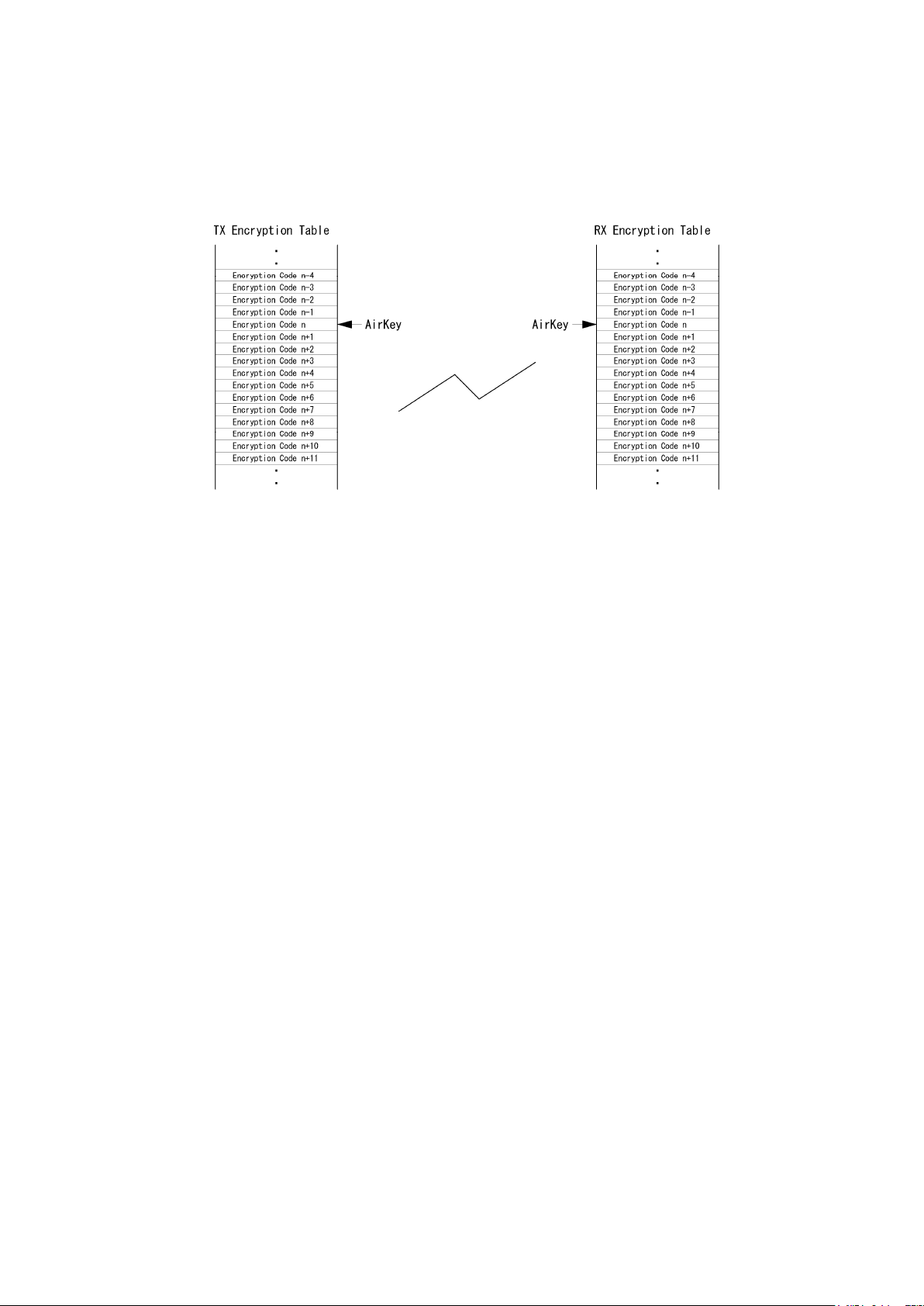
Encryption Method
Using the Master key and algorithm, the encryption table for the data
encode is created. Therefore, the Master key and algorithm must be set to
the same values for both the transmit and the receive units.
The actual encryption code is selected from the encryption table by the Air
Key.
In the Fixed Encription mode (Flag: 00), the transmit data does not contain
the Air Key. At the receive end, therefore, the same Air Key must be
obtained in advance to select the encrption code and decode the signals.
In the Random Encrption Mode 1, 2 (Flag: 40), the Air Key selected at the
transmit end is sent along with transmit data. At the receive end, the
received data will be decoded by selecting the encryption table using the
received Air Key.
In the Random Encrption Mode 3, 4 ( Flag: 50), the random number coded
Air Key is sent along with transmit data. At the receive end, the received
data will be decoded by selecting the encryption table using the received
Air Key.
In the Random Encrption Mode 2, 4 (algorithm 80 – 99), the encryption
code will be changed in every 20 mSec. At the receive end, the received
data will be decoded by changing the encryption code in every 20 mSec.
in synchronization with the original Air Key.
Page 23
22
Encrpt.
SQ
Air Key at
Air Key
Scrambl
Received
Received
Received
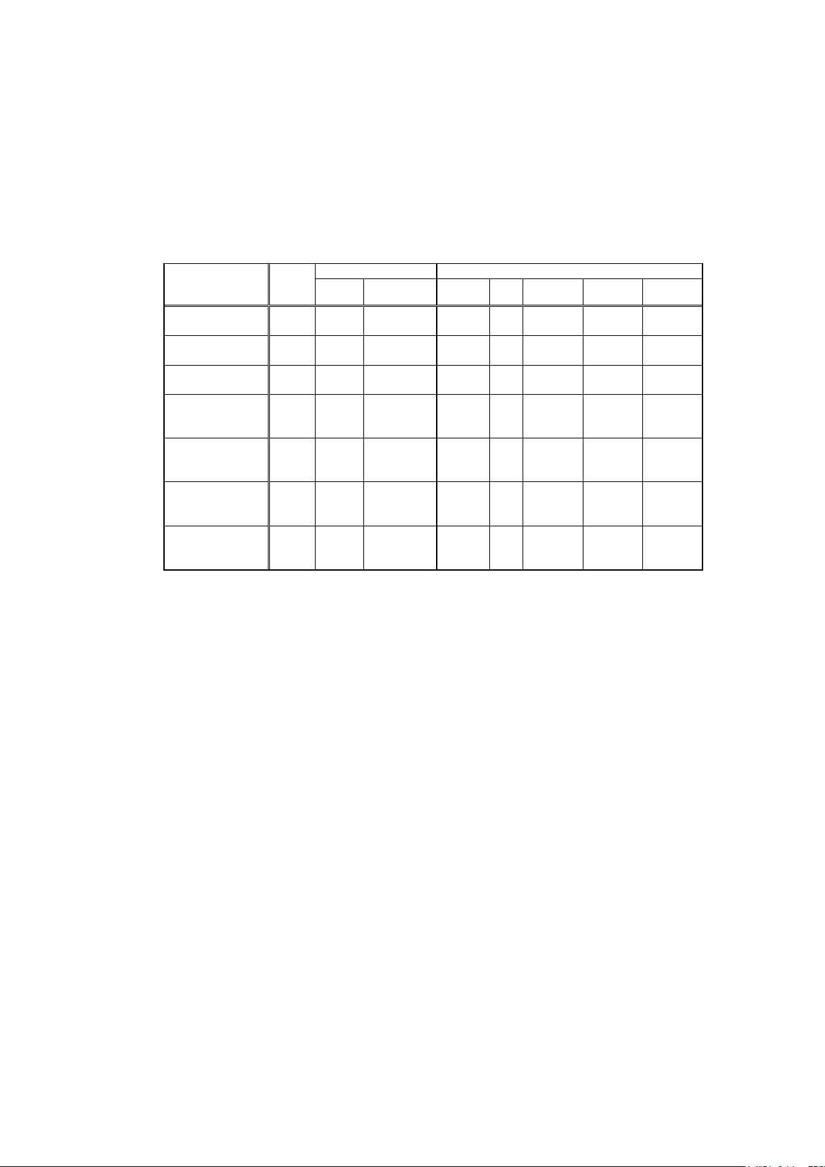
Communication Selection Guidance
The following is a list of communication modes for the ARD9900. Choose the
most suitable communication mode for your applications.
Factory default setting is the non encryption
mode (Communication mode: 0).
Communication
Mode
Non Encrption
Mode
Digital Squelch
Mode
Fixed Encrption
Mode
Random
Encrption Mode
1
Random
Encrption Mode
2
Random
Encrption Mode
3
Random
Encrption Mode
4
(Note: Encrypt: Encryption SQ: Squelch RX: Transmission )
When the falg value is set to [80], enter the algorithm value for either [00] or [01] only.
No other value must be entered.
When the flag value is set to [00], enter algorithm value between [00] to [79]. No other
value must be entered.
Scramble function will be valid only in the random encryption mode when the algorithm is
set to between [80 – 99]. During the communication, the encryption code will be changed
in every 20 mSec according to the algorithm
Mode Setting Function
Flag Algorithm
0 80 00 No No --- --- ---
1 80 01 No Yes --- --- ---
2 00 00-79 Yes No Preset No Fixed
3 40 00-79 Yes Yes
3 40 80-99 Yes No Received
3 50 00-79 Yes Yes
3 50 80-99 Yes Yes
RX
Air Key
Air Key
Air Key
Air Key
TX
Preset Fixed
Preset Variable
Random
number
Random
number
Variable
e
Fixed
Page 24

23
Communication Mode Setting
The communication setting is set into discrete channels.
[Procedures]
1. Using the AMA command, enter the System Management Screen.
2. Select the desired channel on the front panel.
3. Using the ACP command, set the desired commnucation mode setting.
To verify details of the setting, use the ACP command.
ACP [CR]
To verify details of the communication channel, use the ADS command.
ADS [CR]
[Example] ACP [CR]
CH: 5 ID: 12345 NM: FFFFF MD: 0
CH: 5 Channel 5 is selected
ID: 12345 Destination ID is set to 12345
NM: FFFFF Displays the nest mask setting. [ F] is indicating the
digit is valid.
MD: 0 Communication mode is [ 0 ] (Non encryption mode).
Page 25

24
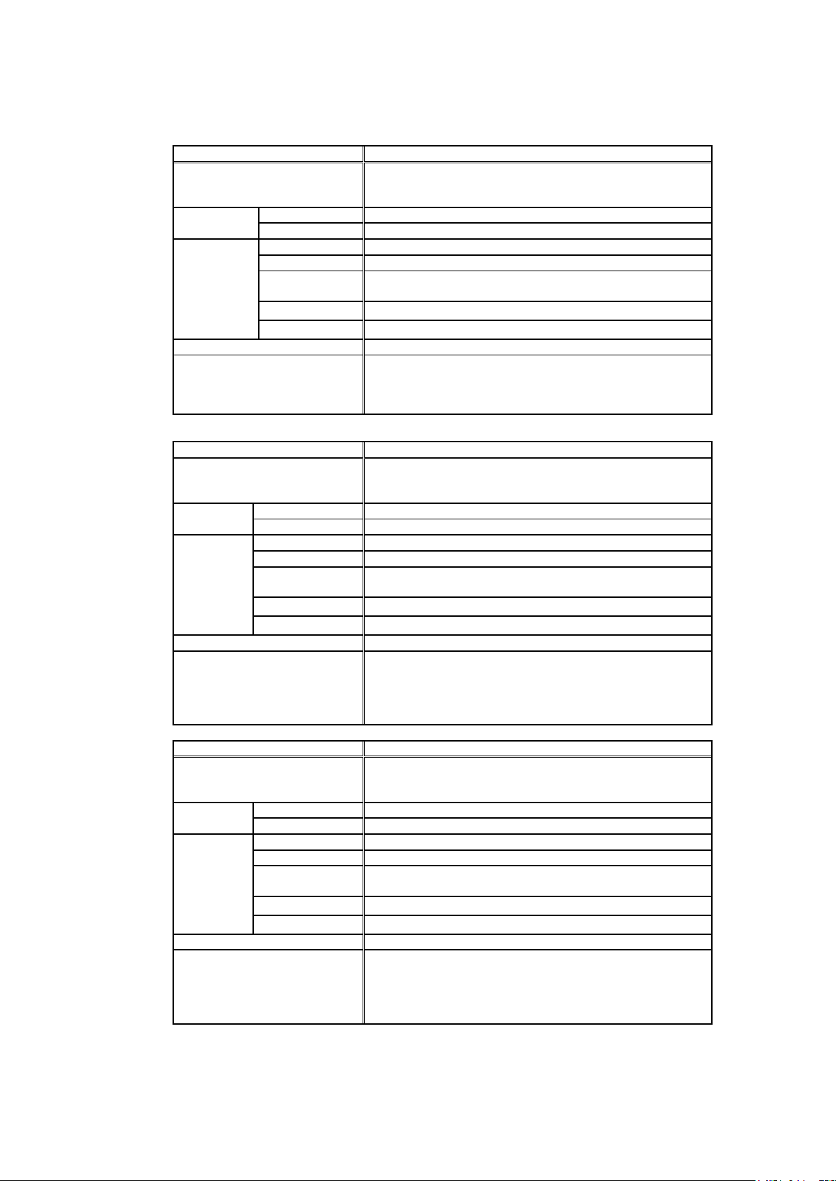
Detailed function of communication mode
[Note: A value of algorithm must be set between [00 ~ 79].
[Caution: Communication mode must be set to the same for transmit end and receive end.]
Mode Non encryption mode
Features Non encryption. Factory default setting. Force receiving
available
Setting Flag 80
Algorithm 00
Functions Encrption No
Squelch No
Air Key at RX
end
Air Key TX ---
Rolling Code ---
Mode Code 0
Remarks Factory default setting
Mode Digital Squelch mode
Features Digital Squelch is available
Setting Flag 80
Algorithm 01
Functions Encrption No
Squelch No
Air Key at RX
end
Air Key TX ---
Rolling Code ---
Mode Code 1
Remarks Squelch will open or close by comparing the destination ID
Mode Fixed Encrption mode
Features Effective against noise. Force receiving is available
Setting Flag 00
Algorithm 00-79
Functions Encrption Yes
Squelch No
Air Key at RX
end
Air Key TX No
Rolling Code Fixed
Mode Code 2
Remarks Air Key, Flag, Algorithm msut be set to the same for both
---
Non encryption
---
and value of the net mask with the receiver’s user ID.
Use the Air Key set at the receive end
parties prior to communication
Page 26
25
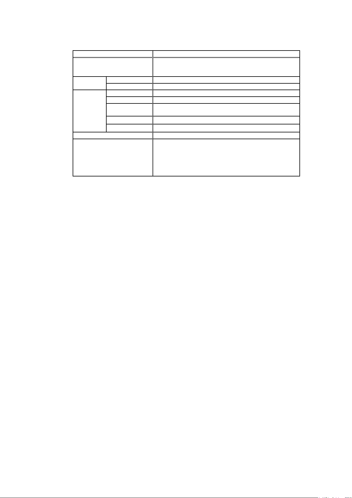
Mode Random Encrption mode 1
Features Communication can be made with the station that has Flag
40 or Flag 50. (The Master key and algorithm must be set
to the same value.)
Setting Flag 40
Algorithm 00-79
Functions Encrption Yes
Squelch Yes
Air Key at RX
Use the Air Key in the transmit data
end
Air Key TX Send the preset code from the transmit end
Rolling Code Fixed
Mode Code 3
Remarks Once algorithm is set to the same, communication can be
made with the statation that has Flag 40 or Flag 50. Since
the Air Key is sent from the transmit end, it is not necessary
to have the same Air Key at the receive end.
Mode Random Encrption mode 2
Features Communication can be made with the station that has Flag
40 or Flag 50. (The Master key and algorithm must be set
to the same value.)
Setting Flag 40
Algorithm 80-99
Functions Encrption Yes
Squelch No
Air Key at RX
Use the Air Key in the transmit data
end
Air Key TX Send the preset code from the transmit end
Rolling Code Will change in every 20 mSec according to the algorithm
Mode Code 3
Remarks Once algorithm is set to the same, communication can be
made with the statation that has Flag 40 or Flag 50. Since
the Air Key is sent from the transmit end, it is not necessary
to have the same Air Key at the receive end. The code will
be scramblked and will change every 20 mSec.
Mode Random Encrption mode 3
Features Communication can be made with the station that has Flag
40 or Flag 50. (The Master key and algorithm must be set
to the same value.)
Setting Flag 50
Algorithm 00-79
Functions Encrption Yes
Squelch Yes
Air Key at RX
Use the Air Key in the transmit data
end
Air Key TX Send the random coded Air Key from the transmit end
Rolling Code Fixed
Mode Code 3
Remarks Once algorithm is set to the same, communication can be
made with the statation that has Flag 40 or Flag 50. Since
the Air Key is sent from the transmit end, it is not necessary
to have the same Air Key at the receive end. The code will
be scramblked and will change every 20 mSec.
Page 27
26
Mode Random Encrption Mode 4
Features Communication can be made with the station that has Flag
40 or Flag 50. (The Master key and algorithm must be set
to the same value.)
Setting Flag 50
Algorithm 80-99
Function Encrption Yes
Squelch Yes
Air Key at RX
end
Air Key TX Send the random coded Air Key from the transmit end
Rolling Code Will change in every 20 mSec according to the algorithm
Mode Code 3
Remarks Once algorithm is set to the same, communication can be
Use the Air Key in the transmit data
made with the statation that has Flag 40 or Flag 50.
Since the Air Key is sent from the transmit end, it is not
necessary to have the same Air Key with the receive end.
The code will be scramblked and will change in every 20
mSec.
Page 28

27
Control Commands
Interfacing to a PC
Using the supplied PC interface cable, connect between the COM connector at the rear
panel (marked as [10101] ) to the serial port of a PC.
[NOTE: Be sure your PC’s serial port is active. Check for correct hardware and software settings!]
Below are the pin assignments of the COM connector of the ARD9900.
ARD9900 COM connector Serial connector of a PC (D-Sub 9 – pin)
Pin # Pin #
1 ---------- 2
2 ---------- 6
3 ---------- 4
4 ---------- 5
5 ---------- 3
6 ---------- 8
7 ---------- 7
8 ---------- 1
GND ---------- GND
Terminal Settings
Communication Speed: 9600 bps
Data Length: 8 bit
Start Bit: 1
Stop Bit: 1
Parity: None
Flow Control: Hardware
Local Echo: None
Specifications: RS-232C compatible
Page 29

28
Command Format
Run a terminal software program, and then turn the power of the ARD9900 on.
The following message should appear on the PC screen:
CMD>
This indicates the ARD9900 is ready to accept commands from the PC.
Each command consists of three (3) alphabetical characters.
CMD>CCC_NN [CR]
CCC: Command (Must be a capital letter)
_ : Space
NN: Parameter
[CR]: Carriage Return
Entering a command without a parameter will display the current parameter (value)
setting.
CMD>CCC[CR]
If an invalid parameter or command is entered, the ARD9900 will respond as follows:
CMD>
?
CMD>
Entering the System Management Screen
Using the AMA command with the master key code, you can enter the System
Management Screen.
CMD>AMA_
( _ : space key)
CMD> (Response from PC)
[Note : The master key code consists of 12 digits of numeric code (0 ~ 9).
[Warning ! ]
The master key code MUST be kept in a secure place. Without the proper
master key code, no code changes can be made.
If you made an entry error entering a setting, correct it in the above entry screen.
If you exit from the master key code setting screen with a wrong code, neither
you nor our factory can change it.
Each command consists of three (3) alphabetical characters.
The factory default is 123456789012]
CMD>CCC_NN [CR]
CCC: Command (Must be a capital letter)
_ : Space
NN: Parameter
[CR]: Carriage Return
************
[CR] ( Enter the master key code.)
Page 30

29
Entering a command without a parameter will display the current parameter
(value) setting.
CMD>CCC[CR]
If an invalid parameter or command is entered, the ARD9900 will respond:
CMD>
?
CMD>
Operator’s Command List
Command Function
AAQ Send VIDEO In signal to VIDEO OUT (to a monitor screen)
ACD Display the last received sender’s ID
ACN Display the last received net mask
ACO Enter the Converse mode
ACS Display the last received sender’s ID
ADC List the current commands
ADS Display current settings
AMA Entering the System Management Screen
ATX Send digital image
AVR Display the current firmware version
Capture image into memory of the ARD9900
Page 31
30
Operator’s command details
AAQ
Function Send VIDEO In signal to the VIDEO OUT (to the monitor screen)
Capture image into memory of the ARD9900
Default None
Format AAQ {0 / 1} [CR]
Parameter 1: Send VIDEO In signal to the VIDEO OUT (to the monitor
screen)
0: Capture image into memory of the ARD9900
Details While AVT command is OFF, [AAQ 0] will be accepted.
Entering AAQ[CR] will respond with the current status.
AAQ ON --- Video signal is passed to the VIDEO OUT port
AAQ OFF --- Video signal is not passed to VIDEO OUT
Example AAQ_0 [CR]
ACD
Function Display the last received sender’s ID
Default 12356
Format ACD [CR]
Parameter None
Details Display the last received sender’s ID
Example ACD [CR]
ACN
Function Display the last received net mask
Default FFF00
Format ACN [CR]
Parameter None
Details Display the last received net mask
Example ACN [CR]
ACO
Function Enter the Converse mode
Default None
Format ACO [CR]
Parameter None
Details Change from the command mode (displaying [CMD>] on the screen)
to the converse mode.
In the converse mode, characters and/or binary data can be sent.
To return to the command mode, press the “C” key while holding the
“Ctrl “(control) key.
Example ACO [CR]
Page 32

31
ACS
Function Display the last received sender’s ID
Default 12356
Format ACS [CR]
Parameter None
Details Display the last received sender’s ID
Example ACS [CR]
ADC
Function List the current commands
Default None
Format ADC [CR]
Parameter None
Details List the current commands
Example ADC [CR]
ADS
Function Display current settings
Default Headerlen: 1.00
AFC = ON
Analog: ON
UserID: 77777
CH: X ID: 00000 NM: 00000 MD: 0
X: Currently selected channel number
Format ADS [CR]
Parameter None
Details Display current settings
Example ADS [CR]
AMA
Function Entering to the System Management Screen
Default 123456789012
Format AMA_ {000000000000 – 999999999999} [CR]
Parameter 000000000000 - 999999999999
Details Entering the System Management Screen by entering the master key
code.
Example AMA_123456789012 [CR]
[Warning ! ]
The master key code MUST be kept in a secure place. Without a master key
code, no code change can be made.
If you made an entry error during an initial setting, correct it under the above
entry screen. Once you exit from the master key code setting screen with a
wrong code, neither you or our factory can change it.
Page 33
32
ATX
Function Send digital image
Default None
Format ATX [CR]
Parameter None
Details An image must be captured and stored into memory before it can
be sent.
Example ATX [CR]
AVR
Function Display the current firmware version
Default None
Format AVR [CR]
Parameter None
Details Displays the current firmware version
Example AVR [CR]
Command List for the System Manager
[Note: 1. The following commands are available under the system management
screen only.
2. After any of the following commands have been changed, the ARD9900 must
be turned power off, and then turned back on to reinitialize.]
Command Function
AAK Set an Air Key code
ACP Set the transmit channel
ADC Display the current commands
ADS List the current commands
AFC Set AFC on/off
AHL Set the duration of the synchronous header signal
ALF Select to add the LF code followed by the CR to the terminal
AMS Change the master code key
APR Reset the unit to the factory’s default setting
ARA Select to monitor digital voice/analog voice or digital voice
ATT Set the output level of the ARD9900 to the radio
AUI Set user ID
AVT Activate/deactivate the video through function
Command details for the System Manager
AAK
Function Set an Air Key code
Default 0000
Format AAK {0000 – 9999} [CR]
Parameter {0000 – 9999}
Details Set an Air Key code
Example AAK_1111 [CR]
Page 34

33
ACP
be
99 (Variable
Function Set the transmit channel
Default CH: X ID: 00000 NM: 00000 MD: 0
X: The current selected channel
Format ACP _ {00000 – 99999} _ {each digit 1/0} _ {80/00/40/50}{00 –
99}[CR]
Parameter 00000 – 99999
Other party’s ID (Do not enter any character)
Each digit 1/0
Net mask setting
0: Net mask / squelch invalid
1: Net mask / squelch valid
(Note: the “1” will be displayed as “F” on the screen.)
80/00/40/50
Flag setting
80: Non encryption communication mode
00: Fiixed encryption communication mode
40: Random encryption communication mode 1 or 2
50: Random encryption communication mode 3 or 4
(Note: When the falg is set to [40], then the Random
encryption mode 1 or 2 will be selected according
to the value of algorithm.)
When the flag is set to [50], then the Random
encryption mode 3 or 4 will be selected according
to the value of algorithm.
00 –99
Algolithum setting
When the flag is set to [80], the algorithm MUST be set to
00 (Non encryption mode) or 01(Digital squelch mode.)
When the flag is set to [00], the algorithm MUST be set
between 00 – 79.
When the flag is set to [40] or [50], the algorithm MUST
00 – 79 (Fixed rolling code mode) or 80 –
rolling code in every 20 mSec.)
Details Each channel can select any desired setting
In the factory default setting, type ACP [CR] will display the following
setting parameters.
CH:0 ID:00000 NM:00000 MD:0
- - - -
- - - Communication mode
- - - [0] Non encryption mode
- - - [1] Digital squelch mode
- - - [2] Fixed encryption mode
- - - [3] Random encryption mode
- - Net mask setting [1] valid, [0] invalid
- Other party’s ID {00000 – 99999}
Channel switch number
[Note: Using the ACP command will NOT display the algorithm
Value. Use the ADS command instead.
Example Channel: 8, ID: 12345, Net mask: 11100, Fixed encryption mode,
algorithm: 20
Set the channel switch to [8].
ACP_12345_11100_0020 [CR]
Page 35

34
ADC
Function Display the current commands
Default None
Format ADC [CR]
Parameter None
Details Display the current commands
Example ADC [CR]
ADS
Function List the current commands
Default Flag: 80
Algorithm: 00
Air Key: 0000
User ID: 77777
CH: X ID: 00000 NM: 00000 MD: 0
X: The current selected channel
Format ADS [CR]
Parameter None
Details List the current commands
Example ADS [CR]
AFC
Function Set AFC on/off
Default ON
Format AFC {ON/OFF} [CR]
Parameter ON: AFC valid
OFF: AFC invalid
Details Set the AFC (Automatic Frequency Control) function on/off.
In the SSB mode, the AFC function must be set to be valid.
In the FM mode, the AFC function may be set to be invalid
Example AFC_ON [CR]
AHL
Function Set the duration of the synchronous header signal
Default 1.00 ( 1 second)
Format AHL {050 – 198} [CR]
Parameter 050 – 198 (0.02 incremental)
Details Set the duration of the synchronous header signal.
{100} means 1.00 second of duration.
Example AHL_146 [CR] - - - Set AHL to 1.46 seconds
Page 36
35
ALF
Function Select to add the LF code followed by the CR to the terminal
Default ON
Format ALF {ON/OFF} [CR]
Parameter ON: Add LF after CR
OFF: Does not add LF after CR
Details Select to add the LF (Line Feed) code followed by the CR (Carriage
Return) to the terminal
Example ALF_ON [CR]
AMS
Function Change the master code key
Default 123456789012
Format AMS_ {000000000000 – 999999999999} [CR]
Parameter 000000000000 - 999999999999
Details Change the master code key
Example AMS_111333444555 [CR]
[Warning ! ]
The master key code MUST be kept in a secure place. Without a master key
code, no code change can be made.
If you made an entry error entering a setting, correct it in the above entry
screen. Once you exit from the master key code setting screen with a
wrong code, neither you nor our factory can change it.
APR
Function Reset the unit to the factory’s default setting
Default None
Format APR [CR]
Parameter None
Details Reset the unit to the factory’s default setting
Example APR [CR]
ARA
Function Select to monitor digital voice/analog voice or digital voice
Default ON
Format ARA_{ON/OFF} [CR]
Parameter ON: Monitor digital voice and analog voice signal
Details Select to monitor digital voice/analog voice or digital voice
Example ARA_ON [CR]
OFF: Only analog voice signal can be monitored
Page 37
36
ATT
Function Set the output level of the ARD9900 to the radio
Default ON
Format ATT_{ON/OFF} [CR]
Parameter ON: Select low level signal output to the radio
OFF: Select high level signal output to the radio
Details Set the output level of the ARD9900 to the radio
Example ATT_OFF [CR] - - - Select high level output
AUI
Function Set user ID
Default 77777
Format AUI_{00000 – 99999} [CR]
Parameter 00000 – 99999
Details Set user ID. The user ID is used in the digital squelch mode
Example AUI_12345 [CR]
AVT
Function Activate/deactivate the video through function
Default ON
Format AVT_{ON/OFF}[CR]
Parameter ON: Activate the video through function
OFF: Deactivate the video through function
Details When the AVT is set to ON, pressing the TX switch will display the “live”
image on the screen. Pressing the TX switch again will capture the image
and send it from the ARD9900.
When the AVT is set to OFF, pressing the TX switch will automatically
capture the image and send it from the ARD9900.
Example AVT_ON [CR]
Page 38

37
Manufacturer: AOR, LTD.
2-6-4, Misuji, Taito-Ku,
Tokyo, 111-0055, Japan
URL: www.aorja.com
US distributor: AOR USA, INC.
20655 S. Western Ave. Suite 112
Torrance, CA 90501
Phone: 310-787-8615
Fax: 310-787-8619
URL: www.aorusa.com
e-mail: info@aorusa.com
April 17, 2013
Printed in Japan
 Loading...