

Page 1
FAST RADIO MODEM
ARD9800
ARD9800
ARD9800ARD9800
Instruction Manual
Multi-Mode And Digital Voice Interface
AOR, LTD.
Authority On Radio communications
Page 2

Thank you for purchasing the AOR ARD9800 M ultimode and Digital Voice Interface.
The ARD9800 is designed to convert your HF radio equipment to a multi mode and digital voice
capable radio without performing any modifications to your transceiver .
Please read through this instruction manual and familiarize yourself with the operation of the
We suggest you keep this instruction manual for future reference.
We believe you will enjoy using the ARD9800 as an enhancement to your enjoyment of amateur radio.
ARD9800
AOR, L TD.
.
1
Page 3

Features:
Digital voice communications using existing analog 2 way radios.
The ARD9800 uses the same audio frequencies (300 Hz ~ 2500 Hz) as microphone audio to
modulate the voice signal. This allows you to use an analog radio as a digital voice transceiv er.
Digital voice communications in the Single Side Band (SSB) mode.
The automatic frequency clarifier function adjusts frequency drift automatically in the SSB mode.
(Approximately up to +/- 125 Hz). Utilizes the OD FM (Multi Carrier Modulation) circuit that is ef fective
against Multi-path or Selective Fading.
Automatic digital receive
Automatic voice signal detector recognizes the received signal as analog or digital, automatically
switching to the appropriate mode.
Digital Slow Scan TV (SSTV) -- Optional memory module (VM 9800) required
Built-in video capture function (NTSC). Compresses the signal into our original adaptive JPEG format.
Send and receive images (similar to analog slow scan TV) in the Digital mode. Built-in video output
connector (NTSC) allows view ing the picture on an external monitor.
Built–in high grade Vocoder (AM BE)
Utilizing high grade digital voice compression; delivers quality digital voice communications.
Built-in FEC error correction
A powerful error correction circuit delivers stable and reliable communications.
Data communications on the HF band
Data communication is possible on the HF (High frequency) bands at no extra cost. (Speed may be
limited by regulations in certain jurisdictions.)
Small and compact unit. Easy to operate.
Simply connect the ARD9800 to the microphone jack. No complicated or risky radio modifications are
necessary .
Utilizes a uniquely designed high performance DSP (Digital Signal Processor) engine
Battery operation for field use.
2
Page 4

Information to the Digital Device user required by the FCC
This equipment has been tested and found to comply with the limits for a Class B digital device, pursuant to Part
15 of the FCC Rules. These limits are designed to provide reasonable protection against harmful interference in a
residential installation.
This equipment generates, uses and can generate radio frequency energy and, if not installed and used in
accordance with the instructions, may cause harmful interference to radio communications. However, there is no
guarantee that the interference will not occur in a particular installation. If this equipment does cause harmful
interference to radio or television reception, which can be determined by turning the equipment off and on, the use r
is encouraged to try to correct the interference by one or more of the following measures:
Reorient or relocate the receiving antenna.
Increase the separation between the equipment and receiver .
Connect the equipment to an outlet on a circuit different from that to which the receiver is connected.
Consult the dealer for technical assistance.
Precautions
T o prevent fire, personal injury , or unit damage, please observe the following precautions:
Do not attempt to adjust this unit unless instructed to do so by this manual.
Do not expose the unit to direct sunlight or place the unit close to heating appliances.
Do not place the unit in excessively dusty , humid, wet areas.
We are not responsible for any damages to the radio equipment due to improper settings or interface.
We are not responsible for any loss of communications due to an unexpected change of propagation or
operating environment.
3
Page 5

T able of Contents
Supplied Accessories ----------------------------------------------------------- 5
Controls and functions --------------------------------------------------------- 5
Front Panel ------------------------------------------------------------------- 5
Rear Panel -------------------------------------------------------------------- 8
T op Panel ----------------------------------------------------------------------- 12
Internal View ------------------------------------------------------------------ 12
Bottom View ------------------------------------------------------------------ 14
Interfacing the ARD9800 ------------------------------------------------------ 15
Connection to a Radio ----------------------------------------------------- 15
Connection to a Microphone -------------------------------------------- 16
Connection to a PC -------------------------------------------------------- 16
Connection to a Power supply ----------------------------------------- 17
Connection to an External speaker ---------------------------------- 17
Level Adjustment ---------------------------------------------------------------- 17
Microphone level ------------------------------------------------------------ 17
Radio Input level ------------------------------------------------------------- 18
Microphone Balance ------------------------------------------------------- 18
Operation ----------------------------------------------------------------------------- 19
Voice Communication ----------------------------------------------------- 19
Digital Voice Communication ----------------------------------- 19
Analog Voice Communication --------------------------------- 19
Data Communication ------------------------------------------------------ 19
Receive ------------------------------------------------------------------ 19
Transmit ------------------------------------------------------------------ 20
Digital Image Communication ------------------------------------------ 21
Receive ------------------------------------------------------------------ 21
Transmit ----------------------------------------------------------------- 21
Specifications ------------------------------------------------------------------------ 22
Control Commands -------------------------------------------------------------- 23
Limited Warranty ------------------------------------------------------------------ 31
Page
4
Page 6
Supplied Accessories
The following items are provided in the box:
Accessory Quantity
----------------------------------------------------------------
Microphone 1
PC interface cable 1
Speaker Cable 1
DC Power cable 1
Microphone Connector 1
Instruction manual (this booklet) 1
Controls and functions
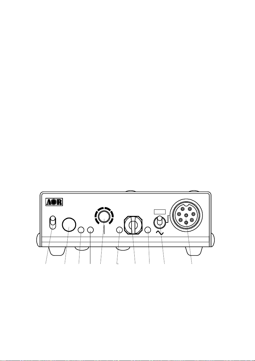
Front Panel
DRA
0089
|
○
MMFEDOOIDARTSA
11110000111100001111
8
9
7
A
6
B
5
MaxMin
C
4
D
3
E
2
F
1
PPPPOOOOWWWWEEEERRRR
BBBBUUUUSSSS
SSSTTTTAAA
MMMOOOODDDDEEE
SSSSPPPPL
AM
VTTTTXXXXS
E
LLLEEEEVVV
OOOOVVVVEEEERRRR
MMMMIIIICCCC
a
c d
b
f
e
a. Power on/off switch
b. TX switch
(Note: This function is available only when an optional memory module has been installed.)
Press this switch to capture and send an image.
When the Video Through Function is activated (AVT command is ON), pressing this
h
g
i
j
5
Page 7

switch will enable output of the video signal connected to the Video Input to also be sent
to the video output port, so that you can monitor the video image. Press this switch again
to capture and send the image through the radio equipment.
When the Video Through Function is de-activated (AVT command is OFF), pressing
this switch will automatically capture the video image and then transmit it through the
radio equipment.
Refer to : Operation -- Digital Image Communication at page 21 for details.
c. 2 color LED
Steady red display ---- The unit is in the transmit mode
Flashing red -- Flashes red while the header information is being sent when in the digital
communication mode. (approximately one second).
Lit in green -- The unit is in the receive mode
Not lit --------- The unit is in the standby receive mode or in the analog voice receive mode.
d. Status LED (ST A LED)
In the data communication mode, lit while unsent data is in the memory . It is lit when the
Video Through Function is activated (Digital Image Communication mode). When the
Video Through Function is de-activated (A VT command is OFF), this LED w ill not be lit.
e. Speaker volume adjustment
Adjustment for the internal speaker output level or the external speaker output level when it
is connected.
f. Operation Mode LED (3 colors)
Indicates the current operation mode:
Green display ----- Digital V oice mode
Red display ------- Analog Voice mode
Orange display -- Data Communication mode
Not lit ---------------- Digital Image Communication mode
g. Microphone Input Level Adjustment
Adjustment for microphone input level
6
Page 8

(This adjustment may be required when using a microphone other than the one that came
with your AR9800.)
Refer to Microphone Level Adjustment at page 17 for details.
In case of unbalanced levels between analog voice and digital voice, perform a
microphone balance adjustment as described below.
Microphone Balance
1. At first, set the proper microphone level in the digital voice mode.
2. Turn off the pow er to the ARD9800. Press and hold the TX switch then turn the
power back on. The Mode LED should flash in orange color indicating the
ARD9800 is in the microphone balance adjustment mode.
3. Holding the PTT switch, and w hile speaking into the microphone, adjust the
microphone level.
4. After the adjustment is completed, push the TX switch to save the new setting. The
ST ALED will light to indicate the setting process is completed.
5. T o complete the operation, turn the power of the ARD9800 off, and turn back it on.
h. Overload indicator
Lit when the microphone input is overloaded (too high).
A proper microphone input level will cause the LED to flash from time to time when
speaking into the microphone at a normal level.
The microphone level can be adjusted with the microphone level controller .
Refer to Microphone Level Adjustment at page 17 for details.
i. Mode switch
Select the Digital voice mode (10101) or the Analog voice mode (~)
When the Analog voice mode (~) is selected, ordinary analog voice communications will
be made. In the receive mode, however , the ARD9800 will automatically detect the mode
of the incoming signal and decode signals accordingly . The LED indicates the respective
operation mode.
7
Page 9
j. Microphone connector
Connect the supplied microphone to this connector.
Below are the pin assignments of the connector .
1. Speaker output -- Monitor output signal is present at this pin.
2. BIAS -- Power source for an electret condenser type of microphone.
5V DC through 2.2Kohm of resistor
3. GND -- Chassis ground
4. TX
T aking this pin to the ground will enable the transmit mode.
(Same operation as the TX switch on the front panel.)
5. D/A
T aking this pin to the ground will force the unit to the digital voice communication
mode. When this pin is left open, the operation mode will be set by the mode
switch on the front panel.
6. MIC PTT -- PTT (Push T o T alk) input.
7. MIC GND -- Microphone ground signal
8. MIC IN -- Microphone signal input
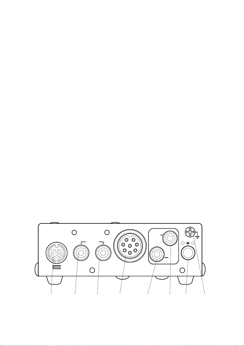
Rear Panel
AOR,LTD.
VIDEO
IN OUT
RADIO
OUT
SP
IN
+‑
DC IN
k
l
m n
o
pq r
8
Page 10

k. Communication Connector (mini DIN 8 pin)
A communication connector for PC (RS-232C)
Pin Number Signal Signal Direction
1 TX ARD9800 PC
2 DTR ARD9800 PC
3 DSR ARD9800 PC
4 GND GND
5 RX ARD9800 PC
6 RTS ARD9800 PC
7 CTS ARD9800 PC
8 NC No Connection
Shell FG Frame ground
Baud Rate: 9600
Start bit: 1
Stop bit : 1
Parity: None
Synchronization: Asynchronous
Flow control: Hardware
l. VIDEO - IN connector (NTSC 1V p – p, 75 ohm)
Connect a video signal source such as a video camera, VCR output, etc.
m. VIDEO – OUT connector (NTSC 1V p – p, 75 ohm)
Connect a video monitor to this connector to monitor a received image or a picture to be sent.
n. RADIO Connector
Using the supplied 8 pin connector, connect the ARD9800 to y our radio equipment. Y ou will
need to wire a cable according to the microphone connector specifications of your radio.
Below are the pin assignments of the connector on the ARD9800.
9
Page 11
Pin number Signal Details
1 MIC GND Microphone ground
2 MIC IN Microphone Input
3 PTT PTT (Push To T alk) input
4 GND PTT ground
5 NC No connection
6 NC No connection
7 GND Ground
8 NC No connection
Note: MIC GND and GND must not
RF feedback will result.
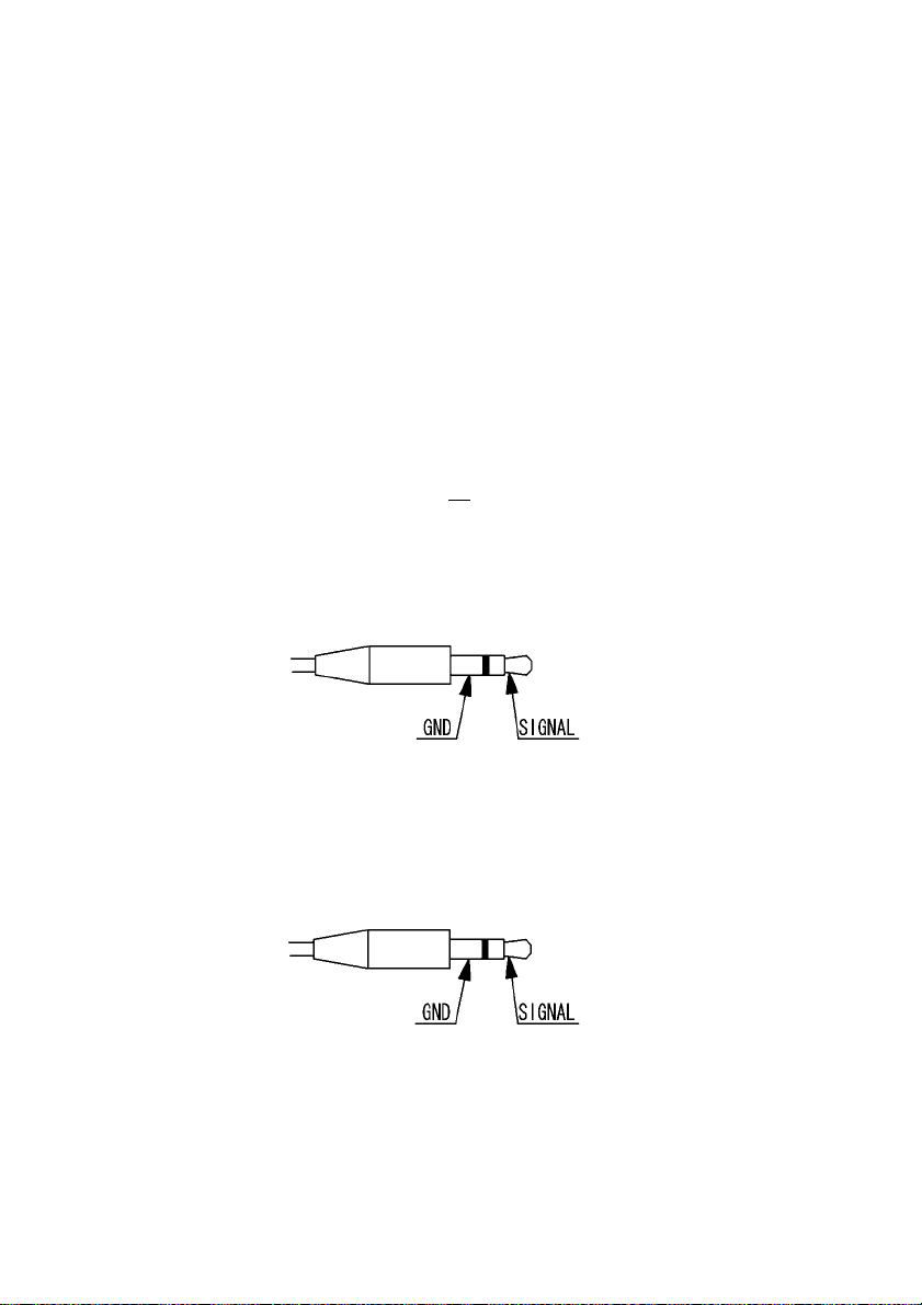
o. SP IN Connector (3.5 mm mono jack)
Connect to the radio equipment’s speaker jack. (Input level: 0.5 V – 5 V p-p)
Note: The output signal from a radio’s “accessory” connector may not be sufficient to use for
this purpose. Use the transceiver’s “speaker out” jack.
p. SP OUT Connector (3.5 mm mono jack)
Connect an external speaker to this jack to disable internal speaker .
q. DC IN Connector (EIAJ T ype 4)
Connect to a regulated power supply. (10.7 ~ 16.0 V DC, Center pin – positive) For lower voltage
battery operation, set the internal jumper terminal for battery operation, and then connect external
batteries .
be connected together in the ARD9800 connector, or
10
Page 12

r. FG
Frame ground
If you have changed the internal jumper for low-voltage battery operation,
battery voltage must be within the range of 5.6 ~6.5 VDC. DO NO T apply
12.0V or severe damage will result, and the warranty w ill be void!
Note: No low battery voltage detector is built-in the ARD9800.
11
Page 13

T op Panel
s. Internal Speaker
Internal View
t. Factory setting jumper
s
v
t
Must be set between 2-3. (Do not change this setting at any time.)
u
w
x
12
Page 14

u. Optional Memory module connector
Insert an optional Memory module to use Digital SSTV functions.
Refer to Memory Module Installation Manual for details.
v. Battery operation selector
Place the jumper between 1 – 2 (NOR) for normal operation.
Change it between 2-3 (BA TT) for battery operation.
If you have changed the internal jumper for low-voltage battery operation,
battery voltage must be within the range of 5.6 ~6.5 VDC. DO NO T apply
12.0V or severe damage will result, and the warranty w ill be void!
Note: No low battery voltage detector is built-in the ARD9800.
w. Internal speaker setting
Jumper setting
1 – 2 Activates internal speaker (default)
2 -- 3 Disable internal speaker
Speaker output is also available from the pin #1 of the microphone connector.
Note: The SP OUT (external speaker output) has priority regardless of the above jumper
setting.
x. Output level setting
Jumper setting
1 – 2 Normal level (default) (LOW)
2 – 3 High level (HIGH)
In case the microphone output level is too low to drive your radio equipment,
place the jumper to the 2-3 position.
Refer to Microphone Level Adjustment at page 17 for details.
13
Page 15

Bottom View
y. Microphone output level
Refer to Level Adjustment Radio Input Level at page 18 for details
Interfacing the ARD9800
Connection to a Radio
Before using your ARD9800, you will first need to wire the cable betw een your radio
equipment and the ARD9800.
For your convenience, an 8-pin of a microphone connector for the ARD9800 is included.
Y ou will need to prepare, however , your own microphone connector for your radio
equipment.
y
14
Page 16

Below are the pin assignments of the 8-pin RADIO connector on the rear panel of the
ARD9800.
Pin number Signal Details
1 MIC GND Microphone ground
2 MIC OUT M icrophone Output
3 PTT (H) PTT (Push To T alk) Output (H level)
4 PTT (L) PTT (Push To T alk) Output (Low level)
5 NC No connection
6 NC No connection
7 GND Ground
8 NC No connection
Note: MIC GND and GND must not be connected together in the ARD9800 connector, or RF
feedback will result.
15
Page 17

Connection to a Microphone
A speaker microphone is included with your ARD9800. However , if you wish to use y our own
microphone with the ARD9800, you may do so by w iring your microphone to correlate w ith the input
jack of the ARD9800. Below are the pin assignments of the Microphone connector of the ARD9800.
1. Speaker output
Monitor output signal is present at this pin.
2. BIAS
Power source for an electlet condenser type of microphone.
5V DC through 2.2K ohm of resistor
3. GND
Chassis ground
4. TX
T aking this pin to the ground will enable to transmit.
(Same operation as the TX switch on the front panel.)
5. D/A
T aking this pin to the ground will force the ARD9800 to the Digital v oice
communication mode.
When this pin is left open, the operation mode will be set by the mode switch on
the front panel.
6. MIC PTT
PTT (Push T o Talk) input.
7. MIC GND
Microphone ground signal
8. MIC IN
Microphone signal input
Connection to a PC
A PC interface cable is included with the ARD9800.
Parameter settings can be made by using terminal software.
Refer to Control Commands at page 23 for details
16
Page 18

Connection to a Power Supply
T o operate your ARD9800, use a regulated power supply .
The operating voltage must be within the range of 10.7 ~ 16.0 V DC (approx imately 200mA).
A DC power cable is also included with the ARD9800.
Color Polarity
========================
RED Positive (+)
BLACK Negative ( - )
Refer to Internal View: Battery operation at page 12 for details
If you have changed the internal jumper for low-voltage battery operation,
supplied voltage must be within the range of 5.6 ~ 6.5 VDC. DO NOT apply
12.0 V or severe damage will result, and the warranty w ill be void!
Note: There is no low battery voltage detector built-into the ARD9800.
.
Connection to an External Speaker
If an external speaker is desired, connect it to the SP OUT jack. This w ill also disable the internal
speaker.
Level Adjustment
Microphone Level
The microphone level has been properly adjusted at the factory with the provided microphone.
Therefore, no further adjustment is needed for normal operation.
If you wish to use your own microphone rather than the included one, you w ill need to wire your
microphone connector to match the pins of the ARD9800, and then adjust the microphone level as
described in the following steps:
17
Page 19

1. Connect your microphone to the Microphone connector of the ARD9800.
2. Turn the [LEV] knob fully counterclockw ise.
3. Press and hold the PTT switch of the microphone, and speak into microphone normally .
4. Slowly turn the [LEV] clockwise until the [OVER] LED flashes occasionally , w ith the peaks of
your voice signal.
Radio Input Level
Perform the following steps to adjust the radio input level of your radio equipment:
1. Connect the microphone to the ARD9800, and then connect the ARD9800 to your radio
equipment. Finally , Connect the ARD9800 to a power supply .
2. Turn the output level adjustment on the bottom of the ARD9800 fully counterclockwise. Turn
the power on to the ARD9800. T urn the power on to your radio equipment.
3. Set the mode switch to the Digital mode [10101].
4. Press the [PTT] switch to transmit from the radio equipment.
5. Adjust the microphone gain of the radio equipment until the ALC function just activates.
6. If the microphone gain is too low, readjust the output lev el on the bottom of the ARD9800.
Microphone Balance
adjust the audio balance, perform the following steps:
If the output level of analog voice and digital voice are not equal, an adjustment can be made. T o
1. First, set the proper microphone level in the digital voice mode.
2. Turn off the pow er to the ARD9800. Press and hold the TX switch then turn the pow er back
on. The MODE LED should be blinking orange, indicating the ARD9800 is in the
microphone balance adjustment mode.
3. Hold ing the PTT s witch, and while speakin g into the m icrophone, adj ust the mic rophone
level.
4. After the adjustment is completed, push the TX switch to save the new setting. The ST A LED
will light to indicate the setting process is completed.
5. T o complete the operation, turn the power of the ARD9800 off, and then turn back it on.
18
Page 20

Operations
Note: All adjustments must be properly performed before operation.
Voice Communication
Y our ARD9800 is capable of Digital V oice Communications and Analog Voice C ommunication.
In the receive mode, the ARD9800 will automatically recognize the type of communication, and set the
appropriate operation mode.
In the transmit mode, the operation mode can be selected by using the front Mode switch.
Digital Voice Communication
Set the mode switch [10101 - ~] upward to the digital mode position. [10101]
Press and hold the PTT switch of the microphone. The ST A (Status) LED w ill flash for about 0ne (1)
second while sending a data header signal.
When the LED stops flashing, speak into the microphone normally.
Analog Voice Communication
Set the mode switch [10101 - ~ ] downward to the analog mode position. [~] Press and hold the PTT
switch of the microphone, and speak into the microphone normally .
Data Communication
Receive
19
Run a terminal software program to control the ARD9800, and to enter control commands.
Refer to Control Commands at page 23 for details
Tw o different types of data, ASCII data or binary data, can be used.
Both data can be mixed as communication data.
Enter the command [ACO] to go into the converse mode.
The received valid data will be decoded and displayed on the PC screen.
If received data is missing, (which may occur during poor propagation conditions) “garbage” data
may be displayed on the PC screen.
Page 21

Transmit
Enter the command [ACO] to go into the converse mode.
Ty pe text from the keyboard, then hit the enter key at the end of the text.
NNNNNNNN [CR]
NNNNNNNN ASCII character
[CR] Carriage Return
Note: Maximum data length is 2046 bytes per packet.
T o send binary data, add [FE] (hexadecimal) to a header and footer w ith the data.
FE BBBBBBBBBBBBBBBB FE
BBBBBBBBBBBBBBB Binary data
FE ID as a binary data
Note: If you need to insert the data [FE] in hexadecimal in the middle of the text,
convert it into two (2) bytes of hexadecimal data.
FE FDD8
If you need to insert the data [FD] in hexadecimal in the middle of the text,
convert it into two (2) bytes of hexadecimal data.
FD FDDD
Note: Maximum data length is 2046 bytes per packet.
At the receive side, the data will be automatically decoded and displayed on the PC screen.
If the [ALF] command is set ON, the LF (line feed) code will be added at the end of received
data.
20
Page 22

Digital Image Communication
Note: An optional memory module is required to use this function.
Receive
When valid digital image data is received, it will be decoded and output as a video image from the
VIDEO OUT connector .
If received data is missing during a transmission, that portion will be displayed as invalid (like noise).
Transmit
When pin - 4 of the microphone connector is grounded, the ARD9800 starts sending the image.
Note: When the Video Through Function is activated (A VT command is ON), pressing the T X switch
will enable output of the video signal connected to the Video Input to also be sent to the video
output, so that you can monitor the video image. Press the TX switch again to capture the
image and then transmit it through the radio equipment.
When the Video Through Function is de-activated (AVT command is OFF), pressing the TX
switch will automatically capture the video image and then transmit it through the radio
equipment.
A Progress indicator will display on the monitor during image transmission.
21
Page 23

Specifications
Modulation Method
Auto Frequency
Offset
Error Correction Data: Reed Solomon + Vitabi Decoder V oice: Golay + Hamming
Header 1 second, 3 tone + BPSK training pattern for synchronization
Digital Audio AM BE ® 2020 Coder/Decoder
Mode Selection Receive: Automatic selection
Video Compression AOR original JPEG format
Video Input/output NTSC (NTSC 1Vp-p 75ohm)
Power Requirement 10.7 ~ 16 V DC (Approximately 200 mA @ 12 V DC)
Communication RS-232C Asynchronous, 9600 bps (setting / data)
I/O Connectors Microphone: 8 – pin metal
Dimensions 100 (w) x 32 (h) x 156 (d) (mm)
OFDM Band Width: 300 Hz ~ 2.5 KHz, 36 carrier
Symbol Rate 20 mS (50 Baud)
Guard Interval 4 mS
T one Space 62.5 Hz
Individual T one
Modulati on
Method
+/- 125 Hz
Transmit:
Data communication mode: Automatic exchange according to TX request from
PC
Digital voice mode: Manually selected by the mode sw itch
Digital Image mode: Manually selected by pressing the TX switch
Analog voice mode: Manually selected by the mode sw itch
6.0 V DC with battery operation ( 5.6 ~ 6.5 V DC)
1 15.2 kbps (image)
Radio: 8 – pin metal
PC interface: Mini 8 – pin DIN
Video In/Out: RCA
Speaker In/Out: 3.5 mm mono jack
Power: EIAJ type 4
4 (w) x 1.3 (h) x 6.2 (d) (inches) Projections not included
Weight: Approximately 600 g (1 lb – 5 oz)
36 carrier: DQPSK(3.6K)
22
Page 24

Control Commands
Interfacing to a PC
Using the supplied PC interface cable, connect between the COM connector at the rear panel (marked
as [10101] ) to the serial port of a PC.
NOTE: Be sure your PC’ s serial port is active. Check for correct hardware and software settings!
Below are the pin assignments of the COM connector of the ARD9800.
ARD9800 COM connector Serial connector of a PC (D-Sub 9 – pin)
Pin # Pin #
1 -------------------------- 2
2 -------------------------- 6
3 -------------------------- 4
4 --------------------------- 5
5 --------------------------- 3
6 --------------------------- 8
7 --------------------------- 7
8 --------------------------- 1
GND ---------------------------- GND
T erminal Settings
23
Communication Speed: 9600 bps
Data Length: 8 bit
Start Bit: 1
Stop Bit: 1
Parity: None
Flow Control: Hardware
Local Echo: None
Specifications: RS-232C compatible
Page 25

Command Format
Run a terminal software program, and then turn the power of the ARD9800 on.
The following message should appear on the PC screen:
cmd>
This indicates the ARD9800 is ready to accept commands from the PC.
Each command consists of three (3) alphabetical characters.
cmd>CCC_NN [CR]
CCC: Command (Must be a capital letter)
_: Space
NN: Parameter
[CR]: Carriage Return
Entering a command without a parameter will display the current parameter (value) setting.
cmd>CCC[CR]
If an invalid parameter or command is entered, the ARD9800 will respond as follows:
cmd>
?
cmd>
24
Page 26

Command List
Command Function
AAQ Send VIDEO In signal to VIDEO OUT (to a monitor screen)
Capture image into memory of the ARD9800
ACO Enter the Conv erse mode
ADC List the current commands
ADS Display current settings
AFC Activate AFC (Automatic Frequency control) function
AHL Set the duration of the synchronization header
ALF Add the LF (Line Feed) code at the end of the C R code
ARA Monitor both digital/analog voice signal or monitor digital voice only
ATT Select output level for the radio equipment
ATX Send digital image
AVT Activate the Video through function when capturing image
AVR Display the current firmware version
25
Page 27

Command details
AAQ
Function Send VIDEO In signal to the VIDEO OUT (to the monitor screen) Capture image
Default None
Format AAQ {0 / 1} [CR]
Parameter 1: Send VIDEO In signal to a VIDEO OUT (to the monitor screen) 0: Capture
Details While AVT command is OFF, [AAQ 0] will be accepted.
Example AAQ_0 [CR]
ACO
Function Change from the Command mode to the Converse mode
Default None
Format ACO [CR]
Parameter None
Details Change from the Command mode (while cmd> appears on the PC screen) into
Example ACO [CR]
into memory of the ARD9800
image into memory of the ARD9800
Entering AAQ[CR] will respond with the current status.
AAQ ON --- Video signal is passed to the VIDEO OUT port
AAQ OFF ---- Video signal is not passed to VIDEO OUT
Note: Optional memory module MUST be installed to use this function.
the Converse mode.
In the Converse mode, data from the PC keyboard can be sent.
T o return to the Command mode, enter [Ctrl – C] (holding the Control key while
entering the C.)
26
Page 28

ADC
Function List the current commands
Default None
Format ADC [CR]
Parameter None
Details Lists the current commands
Example ADC [CR]
ADS
Function Display current settings
Default Headerlen : 1.00
AFC = ON
Analog : ON
Format ADS [CR]
Parameter None
Details Displays the current parameter settings
Example ADS [CR]
AFC
Function Activate AFC (Automatic Frequency control) function
Default On
Format AFC {ON/OFF} [CR]
Parameter ON: Activates the AFC function
OFF: Deactivates the AFC function
Details Must be set to ON in the SSB mode
Set to OFF in the FM mode
Example AFC_ON [CR]
27
Page 29

AHL
Function Set the duration of the synchronization header
Default 100 (1 second)
Format AHL {050 – 198} [CR]
Parameter 050 – 198 (0.02 incremental)
Details Sets the duration of the synchronization header
{100} represents 1.00 second .
Example AFC_146 [CR] Set duration to 1.46 seconds.
ALF
Function Add the LF (Line Feed) code at the end of the CR code
Default ON
Format ALF {ON/OFF} [CR]
Parameter ON : Add the LF code at the end of the CR code
OFF : The LF will not be added to the end of the CR code
Details W hen this c ommand is se t to ON, it fac ilitates t he entry of new da ta from th e
transmit terminal, as a new line is automatically started (and the previous line is
automatically sent).
Example ALF_ON [CR]
ARA
Function Monitor both digital/analog voice signals or monitor digital voice only
Default ON
Format ARA_ {ON/OFF} [CR]
Parameter ON : Monitor digital voice and Analog voice
OFF : Monitor Digital voice only
Details Monitor both digital/analog voice signal or monitor digital voice only
Example ARA_ON [CR]
28
Page 30

ATT
Function Selects the output level to the radio equipment
Default ON
Format A TT_ {ON/OFF} [CR]
Parameter ON : Lower level
Details Selects the output level to the radio equipment
Example ATT_ON [CR]
ATX
Function Send digital image
Default None
Format A TX [CR]
Parameter None
Details An image must be captured and stored into memory before it can be sent.
Example A TX [CR]
AVT
Function Activate the Video through function when capturing an image
Default ON
Format A VT_ {ON/OFF} [CR]
Parameter ON : Activate the Video through function
Details When the AVT command is ON, pressing the TX switch will enable output of the
Example A VT_ON [CR]
OFF : Higher level
Refer to Level Adjustment at page XX for details
Note: Optional memory module MUST be installed to use this function.
OFF : Deactivate the Video through function
video signal connected to the Video Input to be passed to the video output so that
you can monitor the video image. Press the TX switch again to capture the image
and then transmit it through the radio equipment.
When the AVT command is OFF, pressing the TX switch will automatically
capture the video image and then transmit it through the radio equipment.
29
Page 31

AVR
Function Display the current firmware version
Default None
Format A VR [CR]
Parameter None
Details Displays the current firmware version
Example A VR [CR]
30
Page 32

LIMITED WARRANTY
AOR USA, Inc. (AOR) warrants its products as described below:
AOR will repair or exchange equipment as a result of defects in parts or w orkmanship for a period of one year
from the date of original retail purchase from an authorized AOR dealer .
Exclusions
The following items are not covered by the AOR limited w arranty:
1. Products that are damaged through accident, abuse, misuse, neglect, or user modifications.
2. Problems that arise through failure to follow directions in the owner’s manual.
3. Exposure of the product to adverse or severe weather conditions, including temperature extremes or water ,
including rainfall or immersion.
4. Exposure to toxic materials, biohazards, radioactive materials or other contamination.
5. Repairs attempted by parties other than AOR or its authorized personnel.
6. Damage that results from improper installation, including improper voltage and/or reversed polarity , or
exposure of a receiver to signal levels exceeding specifications.
7. Damage resulting through the use of accessories from manufacturers other than AOR.
8. Equipment that has had serial numbers removed or altered in any way .
9. Damage that occurred as a result of shipment. Claims must be presented to the carrier.
10. AOR is not responsible for any costs arising from installation or reinstallation of the equipment, nor for any
consequential (such as loss of use) damage claims.
Obtaining Warranty Service
1. Y ou are responsible for shipping the product to AOR and any related costs.
2. Warranty claim must be accompanied by a legible copy of the original product purchase receipt.
3. Y ou must include a description of the problem(s) encountered with the product.
4. Y ou must include your name, a valid ground shipping address (including zip code) and telephone contact
information.
5. AOR will ship the repaired (or replaced) product by ground transport.
31
Page 33

Limitations
Any and all implied warranties, including those pertaining to merchantability and utility for a specific purpose are
limited to the duration of this limited warranty .
AOR’s limits on warranty pertain only to the repair or , at its option, replacement of defective products. AOR shall not
be liable for any other damages, including consequential, incidental or otherwise, arising from any defect.
Some states do not allow limitations on how long an implied warranty lasts and may not allow the exclusion of
incidental or consequential damages. As such, the above limitations may not apply in every case. This w arranty
gives you specific legal rights and you may have other rights that apply in your state.
If you have questions about this limited warranty , or the operation of your AOR product, contact AOR at
(310) 787-8615 during normal business hours (9 am ~ 5 pm Pacific Time Zone), or wr ite to AOR, 20655
S. Western Ave., Suite 112, T orrance, CA 90501. Y ou may also send a fax to AOR at (310) 787-8619. Additional
information is available at the AOR web site: www .aorusa.com
We suggest attaching your purchase receipt to this half of the warranty information sheet and that you keep this
information in a secure location.
AOR Model Number __________________________
Serial Number ________________________________
Dealer Name _________________________________
Purchase Date ________________________________
32
Page 34

AOR, L TD.
2-6-4, Misuji, T aitok-Ku
T okyo, 1 1 1-0055, Japan
http://www .aorja.com
AOR USA, INC.
20655 S. Western Ave. Suite 112
T orrance, CA 90501, U.S.A.
Phone: 310-787-8615
Fax: 310-787-8619
http://www .aorusa.com
info@aorusa.com
Copyright © 2003
All rights reserved
Rev . 1. 2
33
 Loading...