

Page 1

Contents
(1) T able of contents .......................................................................... 1
(2) Introduction ................................................................................... 2
2-1 Key information and common menus .................................. 3
2-2 Accessories supplied .......................................................... 4
(3) Major Features .............................................................................. 4
(4) Precautions ................................................................................... 4
4-1 Location .............................................................................. 4
4-2 Looking after your receiver ................................................... 5
4-3 Power requirements ............................................................ 5
4-4 Aerial (antenna) connection ................................................. 5
(5) Controls and functions ................................................................ 6
Front panel
5-1 On/Off power switch ............................................................ 6
5-2 S-meter (signal strength meter) ........................................... 6
5-3 Liquid Crystal Display (LCD) ................................................ 6
5-4 Main (large) rotary tuning control - MAIN DIAL .......................... 8
5-5 Sub (small) rotary tuning control - SUB DIAL ............................ 8
5-6 Torque adjustment (MAIN DIAL brake) ..................................... 8
5-7 Removable feet ................................................................... 9
5-8 Internal speaker .................................................................. 9
5-9 SQ - squelch control (plus RF control) ................................. 9
5-10 Volume control (AF GAIN) ................................................. 10
5-11 ACC 1 accessory number one socket ................................ 10
5-12 Headphone socket ............................................................. 10
5-13 Front panel keys ................................................................ 10
Rear panel
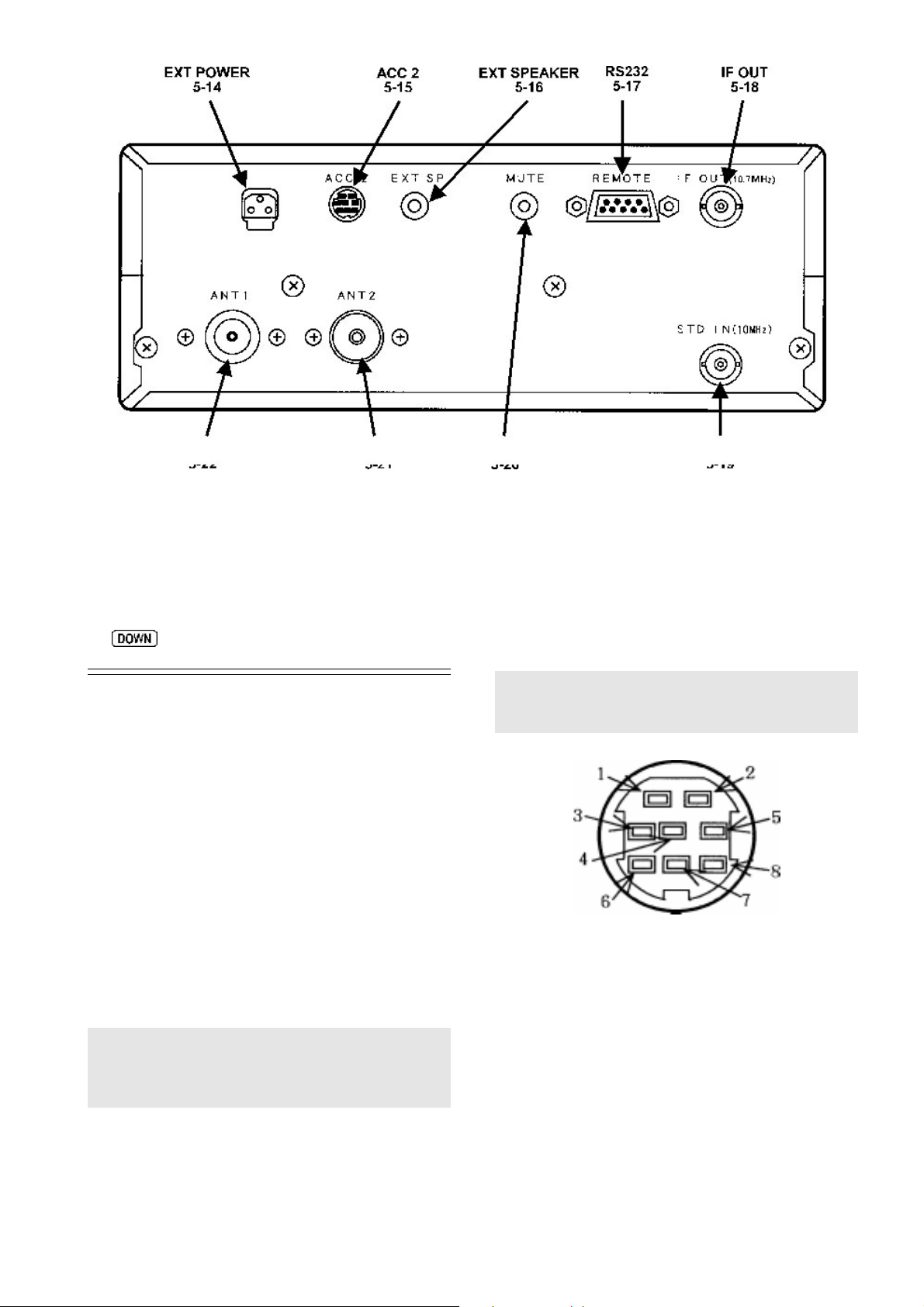
5-14 DC 12V - external power connection .................................. 15
5-15 ACC 2 (accessory 2 socket) ............................................. 15
5-16 EXT SP - external speaker output socket ........................... 16
5-17 REMOTE - RS232C computer control port ........................ 16
5-18 I.F. OUTPUT (10.7 MHz) ................................................... 16
5-19 STD IN (10 MHz) ............................................................... 16
5-20 MUTE ............................................................................... 16
5-21 ANT 2 ............................................................................... 17
5-22 ANT 1 ............................................................................... 17
(6) Basic manual operation of the receiver ..................................... 17
6-1 Switching on for the first time .............................................. 17
6-2 Changing VFO .................................................................... 17
6-3 Tuning the receiver using the rotary controls ........................ 18
6-4 Entering a frequency via the numeric keypad ....................... 18
6-5 Correction of frequency input via the numeric keypad ........... 19
6-6 Selecting tuning step (increment) ......................................... 19
6-7 Step-adjust .......................................................................... 20
6-8 FREQUENCY OFFSET ....................................................... 22
6-9 Changing receive mode (AUTOMODE) ................................ 22
6-10 IF BANDWIDTH ................................................................ 24
6-11 AF SET - (Audio characteristics) ........................................ 25
6-12 Audio tone eliminator (T-ELMT) ......................................... 27
6-13 DTMF decoder .................................................................. 28
6-14 RF Attenuator & preamplifier ............................................. 28
6-15 CONFIG menu outline of facilities ...................................... 28
6-16 CONFIG - LAMP ............................................................... 29
6-17 CONFIG menu - BEEP ..................................................... 29
6-18 CONFIG - EXTERNAL I.F. output (SDU5000) ..................... 29
6-19 CONFIG - Computer control BPS ....................................... 29
6-20 CONFIG - Advanced aerial switching .................................. 30
6-21 CONFIG - Frequency standard ............................................ 32
(7) Memory banks & channels ............................................................ 33
7-1 Storing receive data into memory - VFO mode ...................... 33
7-2 Memory recall - Recalling receive data from memory ............. 34
7-3 Transfer of memory channel to VFO ...................................... 35
7-4 Changing and deleting memory data ..................................... 35
7-5 Deleting memory channels and banks ................................... 36
(8) SCAN - scanning memory channels & banks ............................. 37
8-1 SCAN - outline introduction to facilities available ................... 37
8-2 Starting to SCAN, considerations .......................................... 37
8-3 SCANNING a memory bank ................................................. 38
8-4 Selecting a single memory bank to scan ................................ 38
8-5 Memory bank linking to scan ALL memory banks .................. 39
8-6 Specifying memory bank linking ............................................ 39
8-7 Scanning a memory bank which is not linked ........................ 39
8-8 SCAN channel PASS (lockout) .............................................. 40
8-9
(9) Additional SCAN facilities ............................................................. 41
9-1 SCAN - PAUSE .................................................................... 41
9-2 SCAN - DELAY .................................................................... 42
9-3 SCAN - LEVEL SQUELCH ................................................... 42
9-4 SCAN - VOICE ..................................................................... 42
9-5 SCAN - MODE (receive mode AM, FM etc) ........................... 43
(10) SELECT SCAN - special
10-1 Tagging scan select channels .............................................. 43
10-2 SELECT SCAN - while in SCAN MODE .............................. 44
10-3 SELECT SCAN while in MEMORY RECALL mode ............. 44
10-4 Starting SELECT SCAN ..................................................... 44
10-5 Deleting all SELECT SCAN channels in one go ................... 44
(11) Priority operation .......................................................................... 45
11-1 Engaging PRIORITY channel .............................................. 45
11-2 Changing PRIORITY channel parameters ............................ 45
(12) SEARCH ......................................................................................... 46
12-1 Manual SEARCH between two VFO frequencies (VA, VB) ... 46
12-2 Simple search (VC, VD, VE) ............................................... 47
12-3 Optimising VFO search parameters ..................................... 48
12-4 Program search banks ........................................................ 49
12-5 Starting program search ...................................................... 50
12-6 Cancelling, restarting program search ................................. 50
12-7 Programming and reprogramming SEARCH BANKS .......... 51
12-8 Deleting PROGRAM SEARCH BANKS ............................... 53
12-9 SEARCH - outline introduction to additional facilities ........... 53
12-10 Linking program search banks ........................................... 54
12-11 Linking only a few search banks ......................................... 55
12-12 Searching a bank which is not selected in BANK LINK ...... 55
12-13 Additional PROGRAM SEARCH facilities (introduction) ..... 55
12-14 PROGRAM SEARCH - PAUSE ......................................... 55
12-15 PROGRAM SEARCH - DELAY ......................................... 56
12-16 PROGRAM SEARCH - LEVEL SQUELCH ....................... 56
12-17 PROGRAM SEARCH - VOICE ......................................... 57
12-18
12-19 AUTO-STORE .................................................................. 58
Cyber Scan
in SCAN mode .................................................. 41
select scan list
overview ................... 43
Cyber Search ................................................................... 57
AR5000 OPERATING MANUAL PAGE 1
Page 2

(13) Frequency Pass .......................................................................... 58
13-1 Register PASS Frequency ................................................ 59
13-2 Manually adding a PASS frequency ................................... 59
13-3 Editing pass frequencies ................................................... 60
13-4 Deleting individual pass frequencies .................................. 60
13-5 Deleting complete banks of pass frequencies ..................... 61
(14) Real time clock ........................................................................... 61
14-1 Displaying the clock .......................................................... 61
14-2 Setting time ...................................................................... 62
14-3 Alarm clock ...................................................................... 63
14-4 ALARM programming ....................................................... 63
14-5 ALARM activation ............................................................. 64
14-6 SLEEP timer .................................................................... 64
(15) Option - Descrambler (voice inverter) - DS8000 .................... 65
15-1 Descrambler installation .................................................... 65
15-2 Descrambler operation ...................................................... 66
(16) Option - CTCSS tone squelch - CT5000 .................................. 66
16-1 Installation of the CT5000 ................................................. 67
16-2 Operation of the CT5000 - overview .................................. 67
16-3 CTCSS SEARCH ............................................................. 67
16-4 CTCSS SQUELCH ........................................................... 68
(17) Optional I.F . filters (500 Hz, 2.5 kHz & 5.5 kHz) ...................... 68
17-1 Fitting the optional 500 Hz filter ......................................... 68
17-2 Installation of other filters .................................................. 69
(18) Trouble shooting - microprocessor reset ............................... 70
18-1 Power Off / On .................................................................. 70
18-2 CPU reset switch .............................................................. 70
18-3 CPU soft reset .................................................................. 70
18-4 AF.SET INT/EXT .............................................................. 71
18-5 What next - dealer support ................................................ 71
18-6 Power-up special key sequences ....................................... 71
(19) Optional accessories ................................................................. 72
(20) Aerials (Antennas) and earth systems .................................... 72
(21) Propagation - short wave bands .............................................. 75
(22) Specification ............................................................................... 76
(2) Introduction
Thank you for purchasing the AOR AR5000 wide band all
mode receiver. The AR5000 uses the very latest NCO
(Numerically Controlled Oscillator) technology to ensure
the highest levels of design, performance and reliability .
It is recommended that you carefully read this handbook
and familiarise yourself with the receiver before placing it
into operation. Every effort has been made to make this
manual correct and up to date. Due to continuous
development of the receiver and by error or omissions
anomalies may be found and this is acknowledged. Most
apparent faults are usually due to accidental misoperation
of the receiver, carefully read all of the manual before
deciding to return the receiver for repair.
Although carefully designed, this receiver (like all receivers)
suffers from a degree of internal noises known as spurii.
They are a product of the receiver’s circuitry and do not
represent a fault.
© This manual is protected by copyright AOR Ltd 1995,
1996. No information contained in this manual may be
copied or transferred by any means without the prior
written consent of AOR Ltd. ® AOR and the AOR logo
are registered trade marks of AOR, Ltd. All other trade
marks and names acknowledged. E&OE.
If you are very familiar with operating similar
equipment you may choose to refer directly to section
(6) once you are sure the precautions are fully
understood.
Operating manual Conventions
Where text appears in a graphic format such as
the key is to be pressed exactly as shown.
For example:
Means press the 4 key followed by the 9 key followed by
the enter key.
,
PAGE 2 AR5000 OPERATING MANUAL
Words contained in speech marks “P ASS” or “ F-PASS
VFO” refer to indications displayed on the Liquid Crystal
Display .
Where the mode of FM is referred to, this indicates
Frequency Modulation (narrow and wide depending upon
I.F. filter selection). For clarity, the triple function [MHz]
[ENT] [TEXT] key is referred to as
.
Note: If you take too long entering data (about 90
seconds) the display will revert to it’s original
condition.
Page 3
2-1 Key information and common menus
Config menu (6-16, 6-17, 6-18, 6-19, 6-20, 6-21):
The five VFOs are assigned special status (6-2):
VFO-A (VA) Manual search between VFO-A
and VFO-B
VFO-B (VB) Manual search between VFO-A
and VFO-B
VFO-C (VC) Simple search
VFO-D (VD) Simple search & accept
frequency from the search mode
VFO-E (VE) Simple search & accept
frequency from the scan mode
Memory write (7-1):
Press and hold the
second and follow the prompts.
Mode selection (6-9):
To change the receive mode, briefly press the
key. The “MODE” legend will flash on the LCD to
confirm that the mode select menu has been activated.
The following modes are available from the MODE
menu: “AUTO”, “FM”, “AM”, “LSB”, “USB” and
“CW”. If automode is currently in use, the legend
“AUTO” will be displayed on the LCD. When you have
made selection, press
To select automode press and hold the
more than one second, the legend “AUTO” is displayed
on the LCD to confirm operation.
key for more than one
to accept the new mode.
key for
Press
LAMP ON
BEEP 4
EXT-IF OFF
BPS 9600
ANT 1
STD.INT 12.8 MHz
Delete menu (7-5, 10-5, 8-8, 12-8, 13-5):
Press
than one second.
DEL MEM-CH
DEL SEL-CH
DEL M-PASS
DEL SRCH
DEL F-PASS
Additional scan facilities (9-1, 9-2, 9-3, 9-4, 9-5):
Press
PAUSE OFF
DELAY 2.0
L-SQ OFF
VOICE OFF
MODE ALL
Additional VFO facilities (12-3):
then press and hold the key for more
AGC (6-9):
Press
When in automode the legend “AUT” is displayed.
AGC OFF
AGC FAST
AGC MIDDLE
AGC SLOW
Audio characteristics (6-11):
Press
A-LPF 3.0 kHz
A-HPF 0.05 kHz
DE.EMP 750
CW.PITCH 0.7 kHz
AUDIO INT
Option menu (6-12, 6-13, 15-2, 16-2):
Press
DE-SCR OFF
CTCSS OFF
DTMF OFF
T-ELMT OFF
(if DS8000 option is fitted)
(if CT5000 option is fitted)
Press
DELAY 2.0
L-SQ OFF
VOICE OFF
Programming search banks (12-7):
Press
LO
HI
MODE FM
IFBW 0.5
STEP 1.000
TXT
Additional search facilities (12-14, 12-15, 12-16,
12-17, 12-19):
Press
PAUSE OFF
DELAY 2.0
L-SQ OFF
VOICE OFF
A.STORE OFF
(set to AUTO if AUTOMODE is used)
(skipped if AUTOMODE is used)
(skipped if AUTOMODE is used)
AR5000 OPERATING MANUAL PAGE 3
Page 4

Clock programming (14-2):
Press
than one second.
SELECT 24H / SELECT 12H
6-25-00 1 / AM.6-25-00 1
TXT 1
4-23-30 2 / PM.4-23-30 2
TXT 2
Alarm clock programming (14-4):
Press
than one second.
ALARM 0-00
ALARM LENGTH 15
ALARM ALM RADIO / ALARM ALM BEEP
ALARM VOLUME 80
then press and hold the key for more
then press and hold the key for more
2-2 Accessories supplied
receiver. This inclusion will greatly simplify both frequency
entry and search programming.
The receiver will
and channel step. Of course, should you wish then both
the mode and channel step may be manually changed as
desired.
automatically
select the appropriate mode
l Wide variety of useful operational features
w High speed
Cyber Scan
and
Cyber Search
w Multi VFO (5-VFO)
w A minimum of 1 Hz tuning rate by NCO
w Frequency Offset facility to help follow
duplex transmission
w RF preamp & attenuator
w Auto aerial selection - programmable
w Wide range of search/scan facilities
w Pre-programmed automode (receive mode,
step size, IF bandwidth)
w Step-adjust for unusual banplans
w Standard TCXO plus external 10 MHz input
w Twin tuning knob (MAIN DIAL has a variable
torque controller)
a.c. mains power supply
Operating manual
Additional extensions for front feet
(3) Major Features
l Large LCD
A large rear illuminated liquid crystal display (LCD)
provides display of receive frequency, mode, etc plus alpha
numeric text along with each search bank and memory
channel.
l Massive memory
A large EEPROM memory store holds a total of 1000
memory channels (100 ch x 10 banks), and 20 search
banks. Each search bank has a total of 100 PASS
frequencies plus a further 100 for VFO operation. This
type of memory store does not require external power or
internal battery power to retain the memory contents. The
real time clock is backed by an additional super capacitor
which will maintain the correct time for approximately 50
hours even with no external power connected to the
receiver.
l Wide frequency coverage, all mode, automode
The AR5000 has a very wide frequency coverage of
10kHz to 2600MHz (acceptable input from 5 kHz) in FM,
AM, USB, LSB & CW. The all new receive circuitry
provides high sensitivity and superior strong signal handling
thanks to the clever RF design which is optimised to each
receiving band with electronic tuning (pre-selector) circuits
up to 1GHz.
Comprehensive bandplan information specific to the target
market area has been programmed into the AR5000
l Other useful features
w Variable beep tone
w Sleep timer On/Off, alarm
w Analogue signal meter for easy reading
w Output terminals for external decoder, etc
w Auto-memory facility (On/Off switchable)
w RS232 PC remote control
w Large capacity EEPROM for memory backup
w Tuning step size from 1Hz to 999.999kHz
(4) Precautions
4-1 Location
Do not use or leave the receiver in direct sunlight
(especially the LCD). It is best to avoid locations where
excessive heat, humidity , dust and vibration are expected.
Always treat the receiver with care.
Take care to avoid spillage or leakage of liquids into the
receiver and a.c. power supply. Special care should be
taken to avoid liquid entering via the power jack and
earphone sockets.
Avoid static discharge from discones or long wire aerials,
earth to a central heating radiator or similar earthing point
in order to discharge the wire before connection to the
receiver. Always disconnect and earth any external aerial
system if an electrical storm is expected.
Avoid a rapid power switch On/Off sequence. If switched
off, leave at least two seconds before switching on again.
Ensure the a.c. mains plug connections are tight and other
d.c. connections (such as cigar lighter plugs) are secure.
Avoid strong RF fields from nearby transmitters. If in doubt,
disconnect the AR5000 from the aerial and switch the set
off.
PAGE 4 AR5000 OPERATING MANUAL
Page 5
4-2 Looking after your receiver
Always keep the receiver free from dust and water. Use
a soft dry cloth to gently wipe the set clean. Never use
chemicals such as benzine or thinners which will damage
certain parts.
4-3 Power requirements
The AR5000 is designed for operation from an external
d.c. supply of 12 ~ 16V at approximately 1.0A minimum.
Always use the mains power supply provided, or a
regulated d.c. power supply of 13.5V @ 1.0A or more
using the optional DC3000 connecting lead. Always switch
the receiver off when connecting or disconnecting the
power lead.
Note: The d.c. input socket uses a special type of
connector. This plug / socket is of a moulded type and
pre-wired, positive is the RED wire. The chassis of the
receiver is negative ground.
The power supply is pre-fitted with the correct mains (a.c.)
plug for the appropriate market. This AR5000 power
supply has no connection to the EARTH pin of the mains
plug. A separate earth may be taken to the outer
connection of the SO239, N-type of BNC rear panel
sockets, then to a water pipe, central heating system
radiator or external earth rod. If fitting a separate external
earth rod, consider the implications carefully if your a.c.
mains supply uses a Protective Multiple Earth (PME)
system. If in doubt consult an expert electrician. Never
earth to a gas pipe!
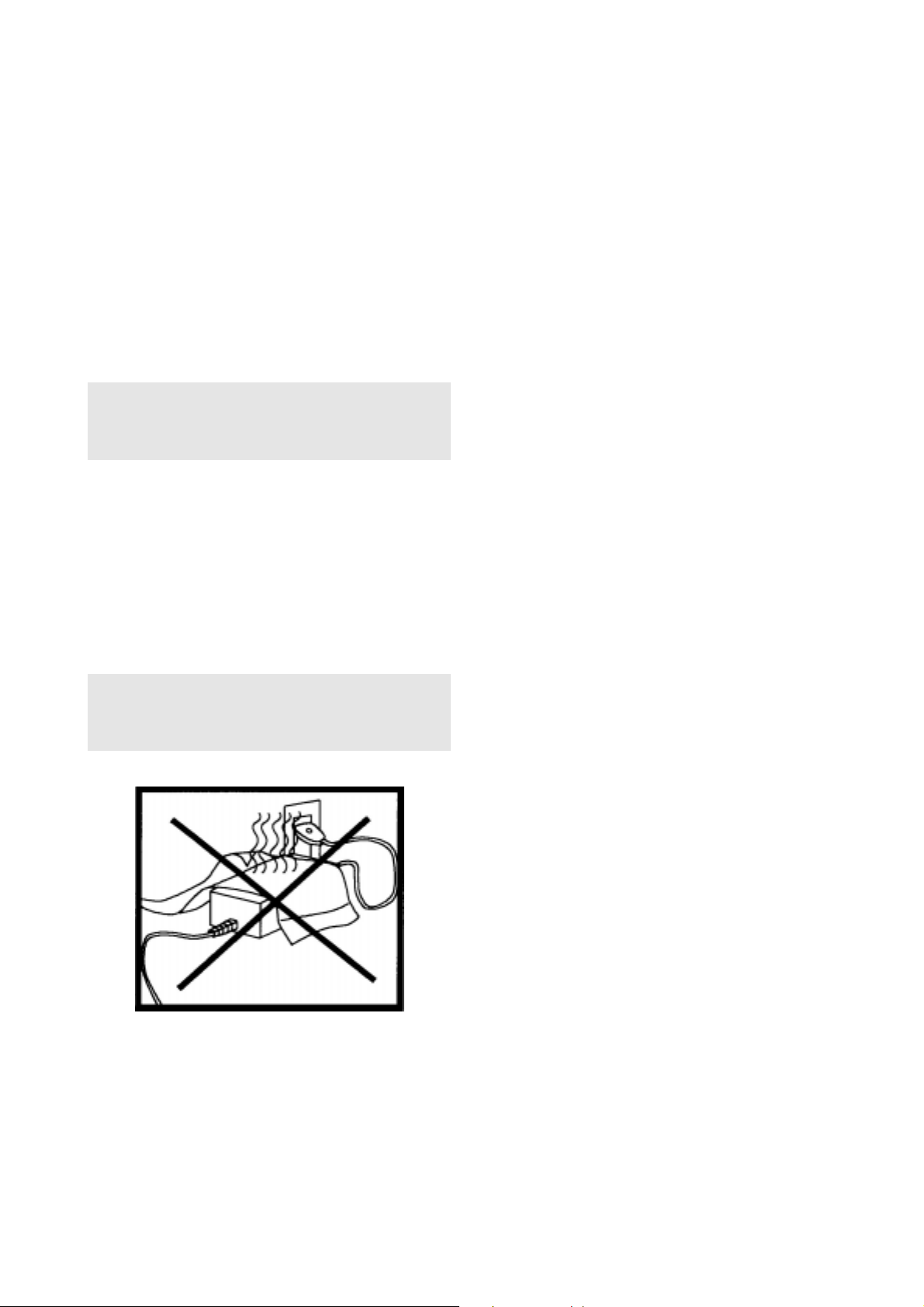
Safety notice: Allow air to circulate around the power
supply, never cover the top with paper , clothing etc. Always
disconnect the power supply from the a.c. mains supply
when not in use.
The aerials input selection may be programmed by the
user for different bands, at default these are:
ANT 1: 50 OHM N-type socket - All frequencies
ANT 2: 50 OHM SO239 socket - User selectable
Aerial inter-series adapters are readily available to convert
from N-type, SO239 etc to BNC or other plugs & sockets
as required allowing straight forward connection to almost
any aerial.
An aerial attenuator system allows selection of AUTO,
0dB, 10dB or 20dB. The attenuator control switches in /
out of circuit the RF preamplifier and attenuator affecting
the sensitivity of the receiver. 20dB may not be selected
above 230 MHz. RF gain is also available in all modes
via a front panel rotary control, this is especially useful in
providing optimum audio quality for SSB operation.
Aerial Tuning Units (A TU)
An A TU can improve the selectivity of any receiver when
listening to the short wave bands when connected to long
wire aerials (other than a short wire of a few metres). This
valuable extra selectivity is created provided by rejecting
out of band signals enabling the receiver to
one band of frequencies while rejecting potentially strong
unwanted transmissions. The AR5000 has a built in
automatic preselected front end
1GHz.
An ATU is usually constructed in a small box with about
two or three controls on the front panel. One disadvantage
however is the need to constantly retune the ATU when
changing frequency. An ATU of this type has no active
circuitry so is known as a
Active short wave desktop loop aerials
passive
for frequencies up to
device.
single out
4-4 Aerial (antenna) connection
The AR5000 has two 50 OHM aerial input sockets fitted
as standard to the rear panel. Further aerials may be
connected using the optional aerial switching unit AS5000
with switching data being fed from a rear panel accessory
socket (ACC 2).
Designed for the short wave bands (such as the AOR
LA320), loop aerials have the advantage of small size
when compared to long wire aerials, and being within easy
reach of the operator it can be rotated to provide directivity .
The circuitry offers a small level of gain with the advantage
of selectivity similar to that of an A TU.
* For further information please refer to section 20 of this
manual regarding aerial and earth systems.
AR5000 OPERATING MANUAL PAGE 5
Page 6

(5) Controls and functions
The AR5000 receiver is housed in a strong metal cabinet.
Controls for operation are located on the front of the
cabinet with connections to the rear.
Front panel
5-1 On/Off power switch
This rectangular shaped plastic button (key) is located in
the top left corner of the front panel and switches the set
On/Off.
To switch the set on, connect a suitable power source
and depress the
then power the set up.
T o switch the receiver off press the
time, the microprocessor will then switch the set off.
switch, the microprocessor will
switch a second
5-2 S-meter (signal strength meter)
The rear illuminated analogue SIGNAL METER is located
to the left hand side of the front panel. Relative strength
of incoming signal is indicated in standard S points where
S1 is weak and S9 is strong. Calibration above S9 is in
dB up to +60dB. As with other receivers, the meter is for
relative
not be totally reliable especially on FM mode.
signal strength comparison and calibration may
5-3 Liquid Crystal Display (LCD)
Display of operational information is provided via a high
contrast wide angle backlit green LCD, this includes
frequency, mode, bandwidth, alpha-numeric comments
for memory channels and search banks etc.
LCD test
The LCD may be tested by holding the
switching on the receiver using the
1 Ensure that set is switched off. Press and hold the
key... don’t let go of it!
2 Press the
may be a two handed operation.
3 Release the
displayed.
4 Press the
key to switch on the AR5000, this
key. All LCD characters will be
key to restore a normal display .
key .
key while
PAGE 6 AR5000 OPERATING MANUAL
Page 7
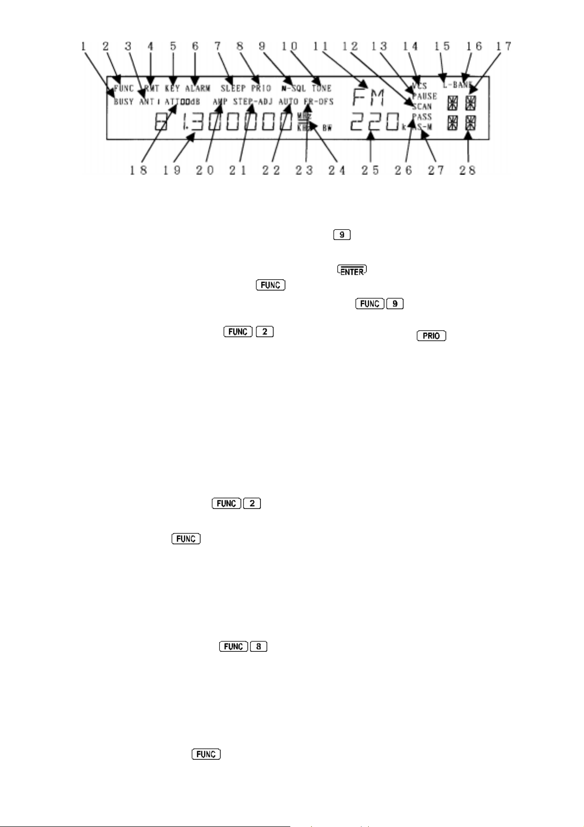
The display is split into 28 specific areas, a summary
of which follows:
1 “BUSY” legend appears when the squelch is open
(signal present).
2 “FUNC” as a reverse legend appears when the
key is pressed signifying that the receiver’s microprocessor
is awaiting the press of another key, where the SECOND
FUNCTION shown in white (not orange) adjacent to the
keys will be activated... an example is
activate the keylock. When the second function is
activated, the “FUNC” legend disappears and often a new
LCD legend appears to confirm selection.
3 “ANT” aerial (ANTENNA) number currently in use. As
standard this will be “ANT 1” or “ANT 2” but may be higher
if the optional aerial switch AS5000 is in use.
4 “RMT” signifies whether the receiver is under normal
keypad control or by a REMOTE device such as the
optional SDU5000 spectrum display unit or computer.
RMT = ReMoTe,
no legend
indicates standard keypad
operation.
5 “KEY” indicates that KEY LOCK has been selected,
this is activated by the key sequence
. Key
lock prevents accidental changing of the receiver’s front
panel controls. When in the locked condition only the
Volume, Squelch, Power and
controls will respond.
6 “ALARM” indicates that the alarm facility has been
activated. The legend “ALARM” will be displayed on the
LCD even when the AR5000 is switched off (as long as
power is maintained to the receiver). At the prescribed
time, the receiver will automatically switch on. It is possible
to program the switch on time, select radio or beep, volume
level and duration before switch off.
To activate the alarm use the sequence
, the
same sequence cancels the alarm as a toggle. This is
very useful for setting up unattended recording or when
using the AR5000 as an alarm clock!
7 “SLEEP” indicates that the sleep timer circuit has been
activated. When the prescribed time for sleep has elapsed
the receiver will switch off automatically ... very useful when
listening to the radio in bed.
To program the sleep time press
then press and
to
hold
for more than one second. A sleep selection
menu will be displayed, use the MAIN DIAL or SUB DIAL to
select the required time (between 1 & 120 minutes) then
press
To activate / deactivate the SLEEP facility use the toggle
sequence
8 “PRIO” indicates when the PRIORITY facility has been
activated by pressing the
key.
9 “N-SQL” and “L-SQL” indicate that the receiver is set
to operate from its squelch circuit, the “BUSY” legend
appearing during activity. In normal use “N-SQL” noise
squelch is used but “L-SQL” (level squelch) may be
selected for search and scan operations. If neither legend
is displayed, the RF GAIN facility has been activated.
10 “TONE” is displayed when the optional CTCSS board
has been selected for tone decoding, often used by
amateur radio repeaters and utility users.
11 “FM”, “AM”, “LSB”, “USB” or “CW” - indicates AR5000
receive mode.
12 “SCAN” is displayed when the memory banks are
SCANNED (automatically checked for activity).
13 “PAUSE” is a selectable parameter for SCAN and
SEARCH modes, the legend indicates that the facility is
in operation. The AR5000 will wait the specified duration
of pause time on a busy frequency before moving off again
even if the frequency is still busy .
14 “VCS” is a selectable parameter (VOICE) for SCAN
and SEARCH modes, the legend indicates that the facility
is in operation. The AR5000 may be programmed to
ignore certain types of blank carriers and unwanted signals.
The value may be selected between 1 to 255 and OFF
while in the scan and search parameter program sub
menus.
15 “L-BANK” as opposed to “BANK” indicates that more
than one scan or search bank has been selected to be
scanned or searched as a group. In other works the banks
have been LINKED, bank link.
16 “BANK” indicates that the receiver is currently in
memory recall mode (no SCAN legend), scan mode (two
lines of bank & channel numbers) or search mode.
AR5000 OPERATING MANUAL PAGE 7
Page 8
In search mode only a bank number and the legend “SR”
is displayed - but no channel number.
the MHz / kHz LCD legends. The available selection of
AGC is: OFF, FAST, MIDDLE & SLOW.
17 The one or two digit number indicates which scan or
search banks have been selected. In scan mode the range
is 0 to 9 (ten banks) and in search mode 00 to 19 (twenty
banks).
18 Attenuator setting. The display is always proceeded
by “ATT” (for attenuator) and followed with dB for level
(decibel). “ATT 00 dB” indicates attenuator OFF, “ATT
10 dB” indicates that 10dB of attenuation has been
applied and “ATT 20 dB” indicates that 20dB of
attenuation has been applied. The attenuator menu is
activated by the
Note: Above 230 MHz only 0dB & 10dB are available
and the RF preamplifier is always in circuit (“AMP” legend
displayed). Below 230 MHz the “AMP” is displayed in the
“00” position.
19 Frequency, text and various status messages are
displayed in this area. There are a maximum of ten digits
providing frequency read-out down to 1Hz resolution. In
text mode a maximum of eight characters may be
displayed for search bank and memory channel
recognition. The frequency red-out is always followed by
the legends kHz or MHz.
Note: frequencies below 3.0 MHz (3000 kHz) are always
shown as kHz.
key.
25 I.F. filter bandwidth is displayed on the LCD in kHz.
The options are:
“220”, “110”, “30”, “15”, “6”, “3”, (“0.5” optional),
i.e. “3K” for 3.0 kHz.
26 “PASS” is displayed to indicate that a memory channel
has been LOCKED OUT so that it will not be scanned,
similarly with a frequency in search mode, it will be skipped.
27 “AS-M” indicates that active frequencies found while
in search mode will be automatically added to memory
bank “0” (Auto Store to Memory). Auto-store is switched
on.
28 The two digit number ranging from 00 to 99 indicates
that the AR5000 is in MEMORY RECALL or SCAN mode
(if the scan legend is also displayed). The two digit number
represents the memory channel number. The
keys or SUB DIAL select bank, the MAIN DIAL selects
memory channel number and the keypad allows direct
access to the three digit bank/channel number i.e.
for bank 1 channel 23, there is no need to press
enter.
In SEARCH mode the letters “SR” are displayed in this
lower right corner of the LCD with the bank number
displayed above.
20 “AMP” is displayed when the RF preamplifier is
switched on. The amplifier is selected in the
ATTENUATOR sub menu accessed by pressing
Note: Above 230 MHz the RF preamplifier “AMP” legend
is always displayed. Below 230 MHz the “AMP” is
displayed in the “00” attenuator position.
21 “STEP” is displayed during entry of STEP SIZE (tuning
increment) for manual tuning or search operations.
“STEP-ADJ” is displayed when the STEP-ADJUST facility
is in use so that unusual bandplans may be correctly
tracked.
22 “AUTO” is displayed when the receive mode selection
is set to AUTO. In this condition the AR5000 will select
the appropriate receive mode, channel step (and many
other parameters) for the frequency entered in VFO mode
and during search programming. This simplifies operation
and speeds up manual changes in frequency.
23 “FR-OFS” is displayed when the FREQUENCY
OFFSET facility is selected. This enables a fixed offset
frequency to be stored in a special bank allowing quick
frequency change and monitoring of duplex pairs such as
inputs to amateur band repeaters or VHF marine traffic.
5-4 Main rotary tuning control - MAIN DIAL
The large rotary tuning control is prominently located on
the front of the cabinet. This control changes the received
frequency up and down in whatever step increment has
been selected between 1 Hz ~ 999.999 kHz. This control
is often referred to as the
Oscillator), a rather historic name for a tuning mechanism.
In this operating manual it is referred to as the MAIN DIAL.
VFO
(Variable Frequency
5-5 Sub rotary tuning control - SUB DIAL
This smaller control may be programmed in a number of
different ways. It too is largely used to tune the receiver
and is intended to make channel tuning easier where
channelised bandplans are in force (such as 2m amateur
band FM allocations etc). The control is extensively used
during the input and changing of operational parameters
such as attenuator, IFBW etc. In this operating manual
the control is referred to as the SUB DIAL.
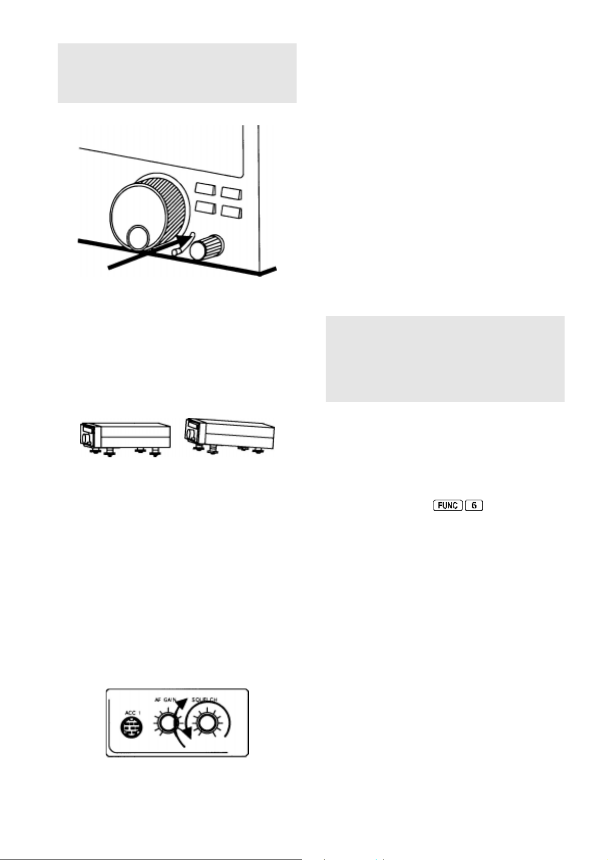
5-6 Torque adjustment (MAIN DIAL brake)
24 “=” AGC OFF indication. When the AGC (Automatic
Gain Control) is switched off, strong signals may sound
distorted... however AGC off may be useful for DX’ing
when the optional 500 Hz Collins mechanical CW filter is
fitted. To ensure that the AGC is not switched off
unintentionally, two parallel bars are displayed between
PAGE 8 AR5000 OPERATING MANUAL
This small slide control affects the
large rotary tuning control (MAIN DIAL), this is useful to help
prevent unintentional frequency change due to accidental
movement of the MAIN DIAL. When the lever is in the
UPWARD position, the MAIN DIAL is FREE RUNNING,
moving the lever downward adds friction to dampen the
control.
free movement
of the
Page 9
Note: A microprocessor
the upper section of the lever’s slot. Reset can be useful
if the receivers operation has been upset due to static
discharge or power supply transients. Details are given in
section 18 of this operating manual.
reset
switch is hidden behind
5-7 Removable feet
The front of the receiver is lifted up clear of the table top
to allow easy access to the front panel controls and clear
visibility of the LCD. The front feet may however be
removed (unscrewing by hand in an anti-clockwise
direction using the knurled disk) for mobile operation.
Additional height may be added by fitting the two spacers
provided with the receiver in the accessories bag.
clockwise until the background noise just disappears
(threshold), this is the most sensitive setting of the control.
In practice the control is usually rotated a little further
clockwise beyond the threshold point to prevent the
receiver from stopping on noise or very weak and
unreadable signals.
If the control is rotated too far clockwise then weaker
signals will be totally lost and only local strong signals will
be heard.
When the squelch control is rotated anticlockwise so that
background noise is audible, the squelch is referred to as
being
OPEN
. In a similar manner, when the squelch
control is rotated clockwise so that the background noise
is muted, the squelch is referred to as being
The squelch is not normally used when listening to short
wave transmissions due to the relatively high short wave
background noise, the usual setting for the control when
listening to short wave is fully anticlockwise (squelch open).
When the squelch is OPEN (busy), a “BUSY” legend is
displayed on the left of the LCD.
Note: Even when the squelch is fully CLOSED a very
low level background noise may still be audible. This is
because the receiver’s audio amplifier circuit is
permanently operational in order to provide fast search /
scan rates and an efficient squelch opening characteristic.
This phenomenon is common with other wide band
receivers on the market today .
When the squelch is set up for normal operation, the
legend “N-SQL” is displayed on the top line of the LCD
slightly centre-right, this stands for Noise SQueLch.
CLOSED
.
5-8 Internal speaker
The AR5000 is fitted with a lower case mounted speaker.
In order to provide best projection of audio from the
receiver, a custom horn has been designed and fitted to
the receivers underside (visible from the front panel).
5-9 SQ - squelch control (plus RF control)
The squelch control is used to eliminate unwanted
background noise when monitoring a normally inactive
frequency and is also used by the AR5000 microprocessor
to determine when a channel is
receiver cannot scan or search when the background
noise is present.
active
(busy).
The
RF GAIN
It is possible to configure the squelch control to function
as RF GAIN by selecting
“N-SQL” legend is removed from the LCD to confirm
operation. The RF GAIN control reduces the level of
amplification applied to the receiver’s I.F. circuits. This
has the effect of reducing the sensitivity of the receiver in
much the same way as the attenuator but is more
controllable.
The usual position for the AR5000 RF GAIN control is
fully anti-clockwise when the set is at its most sensitive.
As the control is rotated clockwise the S-meter will
advance to indicate what strength signal is required to
produce solid and readable results.
The control is most useful on SSB where the RF GAIN
should be adjusted so that the
deflect the S-meter. This will greatly reduce the level of
background noise especially during pauses in speech or
inactivity .
When RF GAIN is used (squelch switched off), the word
“N-SQL” is removed from the top line of the LCD.
on the keypad, the
peaks
of SSB signals just
The squelch control requires careful setting to achieve
optimum operating performance. Rotate the control
AR5000 OPERATING MANUAL PAGE 9
Page 10
5-10 Volume control (AF GAIN)
The volume control is located to the left of the front panel
underneath the signal meter. It is used to set the required
audio output through the loudspeaker or headphone.
When turned fully clockwise the volume is at maximum,
when rotated fully anti-clockwise the volume is reduced
to minimum.
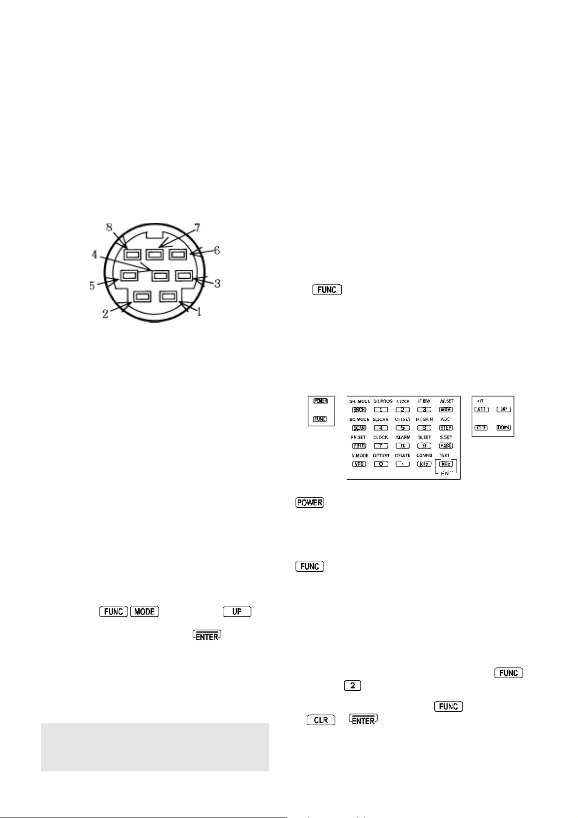
5-11 ACC 1 accessory number one socket
4 & 5 T ape record motor switching using a non-polarised
photo-MOS relay. The switched output is designed for
low voltage (12V) d.c. with a maximum current of 350mA,
the insulating voltage is 40V . The
is 1.2 OHMS.
6 High level audio output. The AR5000 provides both
high and low level audio output for feeding tape recorders
and other remote devices, the output is independent of
volume control level. Pin 6 provides a level of 700mV
RMS @ 600 OHMS, ideal for line output.
switch-on-impedance
A front panel accessory socket is located to the lower left
corner of the front panel which provides outputs for audio,
tape motor switching and discriminator.
A standard 8-pin mini-din connector is used (which is widely
available or the optional CR5000 tape lead may be used).
The pin-outs for ACC 1 are as follows:
1 12V d.c. output with a maximum available current of
30mA (useful for feeding electret microphones and other
low power devices). The voltage will fluctuate depending
upon supply voltage being fed to the AR5000.
2 Detector output (without audio filtering), useful for
improving performance of certain decoders such as
pagers etc. The level output is 180mV RMS and
impedance is 100k OHMS or greater.
7 Low level audio output. Pin 7 provides a level of 2mV
RMS @ 600 OHMS, ideal for microphone input of tape
recorders.
8 Ground.
5-12 Headphone socket
This quarter inch (6.3mm) socket is located on the left
hand side of the front cabinet directly underneath the power
and
be connected with an impedance of 8 OHMS or greater.
When this headphone socket is used, the internal speaker
and any external speaker will be automatically
disconnected.
keys. A pair of headphones or earphone may
5-13 Front panel keys
3 Audio input. The receiver’s audio amplifier stage can
be configured to use signal from an external device rather
than from its own receive circuits. This permits
break-out
reapplied to the receiver for amplification. The input circuit
is configured for a level of 180mV at a nominal impedance
of 100k OHMS.
As the internal audio path needs to be
break-out
configured accordingly. To select EXTERNAL AUDIO
INPUT press
four times to display “AUDIO INT”. Rotate the SUB DIAL
to display “AUDIO EXT” then press
sound from the receiver will be muted until an external
audio signal is applied (fed back in).
Of course, the set’s own audio may be fed out through
the ACC 1 socket and back in again which increases the
receivers flexibility under certain professional monitoring
applications.
Note: At high volume levels, a low level leakage of internal
audio signal may still be heard from the receiver’s
speaker... this is normal and does not represent a fault
(or problem).
of signal for processing (DSP etc) which is then
cut
as part of the
set-up, the microprocessor has to be
then press the
. The usual
key
- POWER
This rectangular shaped plastic key located in the upper
left corner of the front panel switches the set On/Off.
- FUNCTION
This key is located to the upper left of the front panel and
selects SECOND FUNCTION of the front panel keys.
When pressed a reverse “FUNC” appears in the top left
of the LCD. The FIRST function of the keys are printed
on their faces (in orange for words and white for numbers),
the SECOND functions are printed in white directly above
the corresponding key .
For example, the select KEY LOCK, press
or
or tune the receiver using the MAIN
followed by
If you wish to cancel “FUNC” press a second time,
or
DIAL or SUB DIAL.
PAGE 10 AR5000 OPERATING MANUAL
Page 11
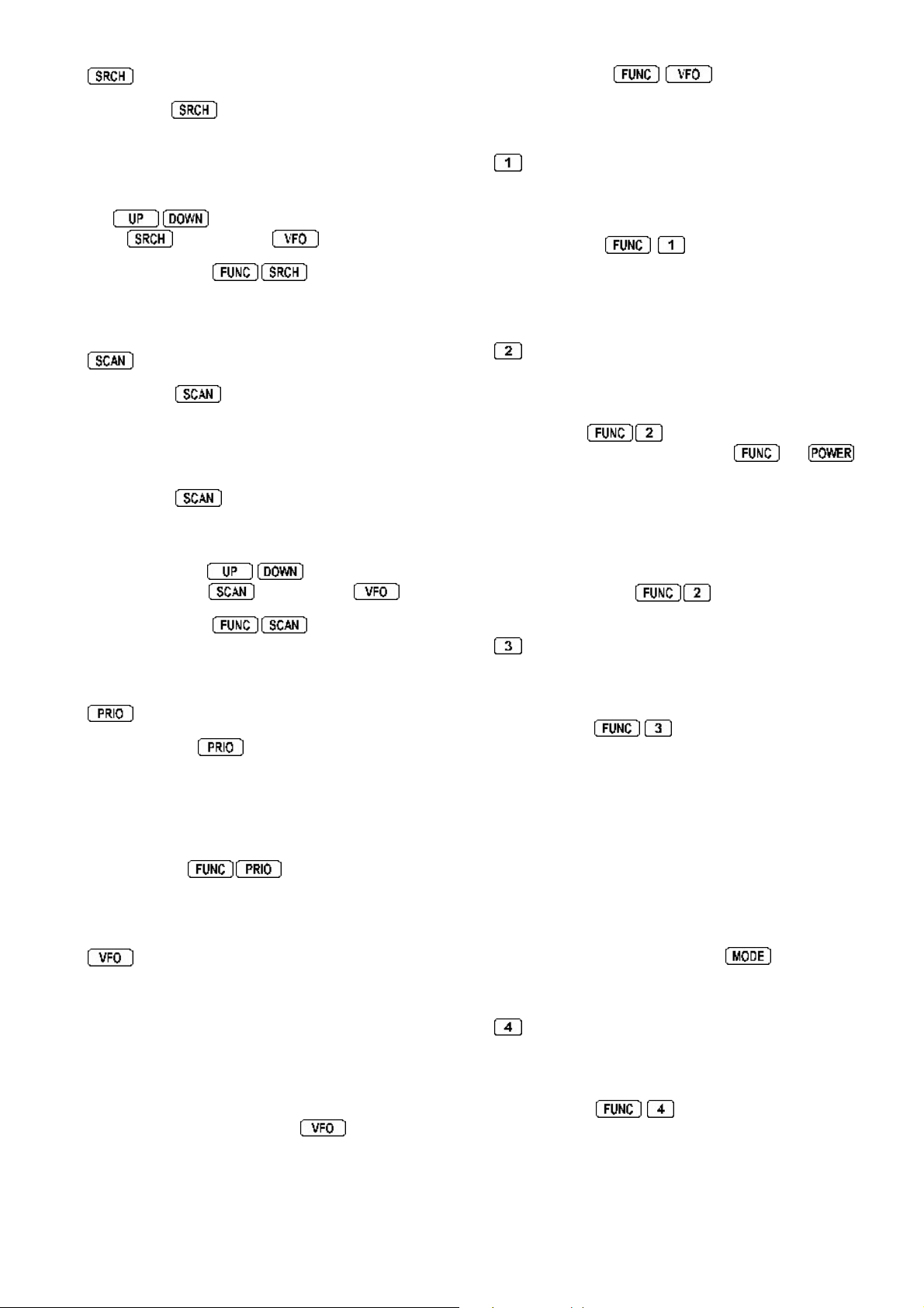
- SR.MODE
Pressing the key places the receiver into program
search mode. There are twenty search banks in total
numbered from 00 to 19. To change the bank number
rotate the SUB DIAL, the bank number appears in the top
right of the LCD. If the receiver stops on an unwanted
busy channel during search, it can be forced onward using
the
press
The key sequence
where bank link, pause, delay , level squelch, voice squelch
and auto-store may be configured.
Pressing the key briefly places the receiver into
MEMORY RECALL MODE. The bank number may be
selected using the SUB DIAL, channel number using the
MAIN DIAL and three digit bank/channel number using the
numeric keypad.
Pressing the
into memory scan mode. There are ten scan banks in
total numbered from 0 to 9. If the receiver stops on an
unwanted busy channel during scan, it can be forced
onward using the
cancel scan press
- SC.MODE
keys or MAIN DIAL. To cancel search
again or press
a second time places the receiver
again or press
activates a sub menu
keys or MAIN DIAL. To
If the sequence
parameters affecting VFO search operation may be
configured: DELAY, L-SQ & VOICE.
- SR.PROG
Figure ONE for the numeric input of frequencies, bank,
channel numbers etc.
The sequence activates the SEARCH
PROGRAM menu where bank number, lower frequency
limit, upper frequency limit, mode, and text comment may
be programmed.
- K.LOCK
Figure TWO for the numeric input of frequencies, bank,
channel numbers etc.
The sequence
disables all front panel keys except for
the rotary tuning controls (MAIN DIAL & SUB DIAL) are also
locked to prevent accidental misoperation of the receiver
when listening to an important frequency. The volume
and squelch controls remain operative.
The legend “KEY” is displayed on the top row of the LCD
left of centre to indicate when key lock is in operation. T o
unlock the keys press
activates the KEY LOCK which
is keyed, additional
and
which acts as a toggle.
,
The key sequence activates a sub menu
where bank link, pause, delay , level squelch, voice squelch
and mode may be configured.
- PR.SET
The priority key activates / deactivates receive
PRIORITY as a toggle. The legend “PRIO” appears on
the centre-top row of the LCD to show that priority has
been activated and the legend “Pr” on the right of the
LCD signifies when the priority frequency is currently active
(busy).
If the sequence
for priority may be selected followed by the interval for
sampling, which is 5 seconds as default.
- V.MODE
The AR5000 has a FIVE VFO system being identified
“VA”, “VB”, “VC”, “VD” & “VE” on the right of the LCD.
The term VFO historically means
Oscillator
contains frequency, mode, step, attenuator and other
relevant information.
and today refers to a tuneable data store which
is keyed, the channel used
Variable Frequency
- IF BW
Figure THREE for the numeric input of frequencies, bank,
channel numbers etc.
The sequence activates the I.F. bandwidth
menu. In normal operation the word “AUTO” will be
displayed toward the centre of the LCD to signify that
automode is in operation and the I.F . bandwidth, receiver
mode and channel step will be automatically selected by
the receiver from its detailed pre-programmed bandplan
data. Selecting a new bandwidth from the list of 220,
110, 30, 15, 6 and 3 kHz is accomplished using the
SUB DIAL, 0.5 kHz is only available if the optional CW filter
has been fitted.
Once automode has been cancelled, it may be reinstated
from the MODE select menu using a short cut... select
AUTO by pressing and holding the
than one second.
- S.SCAN
Figure FOUR for the numeric input of frequencies, bank,
channel numbers etc.
key for more
The first time you enter a frequency via the numeric
keypad, it is best to first press the
displayed to place the receiver in a known state of
operation. The condition of
is generally referred to as MANUAL MODE.
VFO
key until “VA” is
(A-VFO), (B-VFO) etc
The sequence initiates SELECT SCAN, a
special form of scan where memory channels may be
temporarily tagged in a form of notebook.
AR5000 OPERATING MANUAL PAGE 11
Page 12
- OFFSET
- ALARM
Figure FIVE for the numeric input of frequencies, bank,
channel numbers etc.
The sequence
OFFSET where the receiver will automatically jump to a
pre-programmed frequency offset, this is very useful for
checking the other side of duplex transmissions such as
the input frequency of amateur radio repeaters or VHF
marine traffic.
The sequence
than one second activates the FREQUENCY OFFSET
menu where new offsets may be specified and saved /
recalled from one of 48 special locations for easy retrieval
at any time.
- RF GAIN
Figure SIX for the numeric input of frequencies, bank,
channel numbers etc.
The sequence
in place of the squelch control. The “N-SQL” legend is
removed from the LCD to confirm operation. The
RF GAIN control reduces the level of amplification applied
to the receiver’s I.F . circuits. This has the effect of reducing
the sensitivity of the receiver in much the same way as
the attenuator but is more controllable.
initiates FREQUENCY
then hold the
activates the RF GAIN control
key for more
Figure EIGHT for the numeric input of frequencies, bank,
channel numbers etc.
The sequence
can be programmed to switch the receiver on automatically
as an alarm clock or for unattended recording with the
provision to program the active period between 1 and 120
minutes.
The sequence
than one second activates the alarm set menu.
- SLEEP
Figure NINE for the numeric input of frequencies, bank,
channel numbers etc.
The sequence
which can be programmed to switch the receiver off
automatically after a prescribed time period of 1 to 120
minutes... useful if you go to sleep with the AR5000 as a
bedside radio.
The sequence
than one second activates the sleep set menu.
- OPTION
activates the ALARM which
then hold the key for more
activates the SLEEP facility
then hold the key for more
The usual position for the AR5000 RF GAIN control is
fully anti-clockwise when the set is at its most sensitive.
As the control is rotated clockwise the S-meter will
advance to indicate what strength signal is required to
produce solid and readable results.
The control is most useful on SSB where the RF GAIN
should be adjusted so that the
deflect the S-meter. This will greatly reduce the level of
background noise especially during pauses in speech or
inactivity .
When the squelch control is switched off and RF GAIN
used, the legend “N-SQL” is removed from the top line of
the LCD slightly centre-right.
peaks
of SSB signals just
- CLOCK
Figure SEVEN for the numeric input of frequencies, bank,
channel numbers etc.
If the sequence
on the LCD. The SUB DIAL may be used to select one of
two clocks (a second clock is often useful to store world
time of a regular DX site).
The sequence
than one second activates the clock set menu where
display of 12hr / 24hr may be selected, times set for both
clocks and a three character text identifier added to each
clock.
is keyed, the clock is displayed
then hold the key for more
Figure ZERO for the numeric input of frequencies, bank,
channel numbers etc.
The sequence
where the options of DTMF tone display and T-ELMT may
be selected. If the optional boards are fitted, DE-SCR
(descrambler, not available in all countries) and CTCSS
tone selection may also be configured.
- DELETE
Used during the MHz input of frequency to separate the
MHz to the left of the frequency input from the rest of the
entry of kHz and Hz. For example the entry of 88.300000
MHz would be
Note: frequencies below 3.0 MHz (3000 kHz) are always
displayed as kHz regardless of input format.
The sequence of
causes the displayed memory channel to be deleted.
The sequence
than one second activates the DELETE menu where the
item to be deleted may be selected:
MEM-CH memory channel
SEL-CH select scan channel
M-PASS memory channel pass
SRCH search bank
F-PASS frequency pass
activates the OPTION menu
while in memory recall mode
then hold the key for more
PAGE 12 AR5000 OPERATING MANUAL
Page 13
- CONFIG
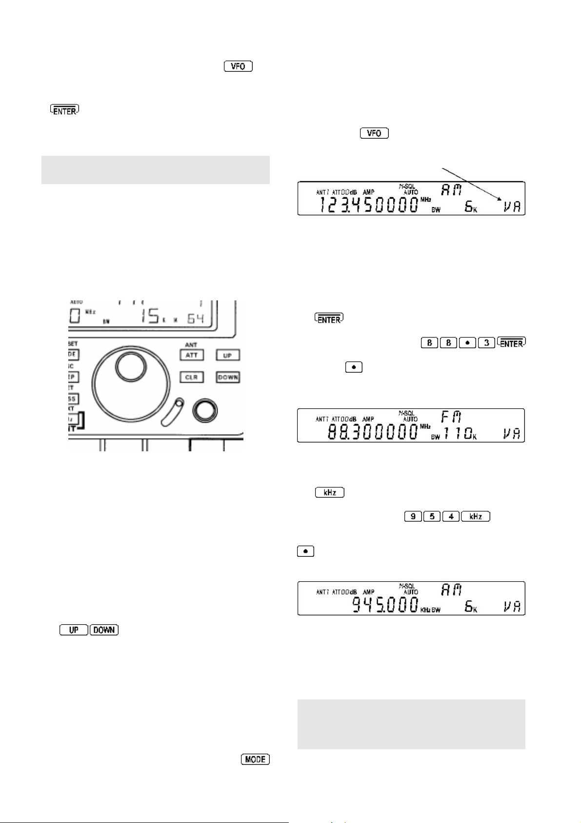
This key is used to accept frequency input via the numeric
keypad in kHz format. For example: T o key in a frequency
of 954 kHz key
954.000 kHz. This has the same effect as keying
0.954MHz or .954MHz
Note: keying a decimal
preceding zero to be added automatically .
The kHz method of frequency entry reduces the number
of key presses required when working with low frequencies
and simplifies operation as short wave listings are often
stated in kHz. Example: Oceanic air traffic 5616kHz or
short wave transmissions Radio Netherlands 5955kHz and
6045kHz.
The key sequence
menu where the lamp On/Off, keypad beep tone status
OFF / volume, external IF output, remote baud rate, aerial
(antenna) automatic switching and internal / external
frequency reference may be configured.
- AF.SET
This key is used primarily to select receive mode.
To select AUT OMODE press and hold the
for more than one second, the receive mode, I.F.
bandwidth and frequency step will be selected by the
AR5000 automatically from its extensive pre-programmed
bandplan listing.
When automode is in operation, the legend “AUTO” is
displayed above the right hand digit (Hz position) of the
frequency red-out.
To over-ride the receive mode, briefly press the
key. The options are: FM, AM, LSB, USB, CW and AUT O.
WFM is supported as a product of the I.F. bandwidth
selected (i.e. 110 or 220 kHz).
The key sequence
(audio frequency set-up) where the AUDIO LOW PASS
FILTER (3.0 kHz, 4.0 kHz, 6.0 kHz or 12 kHz), AUDIO
HIGH PASS FILTER (0.05 kHz, 0.2 kHz, 0.3 kHz or 0.4
kHz), AUDIO DE-EMPHASIS (25, 50, 75, 750 or THRU),
CW PITCH (0.4 kHz, 0.5 kHz, 0.6 kHz, 0.7 kHz, 0.8 kHz,
0.9 kHz, 1.0 kHz or 1.1 kHz) and AUDIO INPUT
(INTERNAL or EXTERNAL) may be configured.
- AGC
This key primarily selects the frequency step size for tuning
the receiver. If the legend ”AUTO” is displayed then the
step size will automatically be determined from the
automode bandplan data, as soon as another selection is
made automode is cancelled.
The standard step sizes offered for the MAIN DIAL are:
0.001 kHz (1 Hz), 0.010 kHz (10 Hz), 0.050 kHz (50 Hz),
0.100 kHz (100 Hz), 0.500 kHz (500 Hz), 1.000 kHz,
5.000kHz, 6.250 kHz, 9.000 kHz, 10.000 kHz, 12.500
kHz, 20.000 kHz, 25.000 kHz, 30.000 kHz, 50.000 kHz,
100.000 kHz and 500.000 kHz.
before the number causes a
activates the CONFIG
activates the AF.SET
the LCD will display
key
In addition unusual step sizes may be entered using
the numeric keypad (i.e.
The SUB DIAL may also be configured for: MAIN (same as
MAIN DIAL), x10 speed of MAIN DIAL, 0.1 kHz, 0.5 kHz, 1.0
kHz, 5.0 kHz, 10.0 kHz, 50.0 kHz, 100.0 kHz, 500 kHz or
1000.0 kHz (1 MHz).
for 200 Hz).
for 22 kHz or
AGC
The key sequence
(Automatic Gain Control) menu.
In FM mode the options are AGC ON / OFF and in other
modes are OFF , F AST, MIDDLE and SLOW. When AGC
OFF has been selected, two horizontal bars are displayed
on the LCD between the kHz and MHz legends.
FM: AGC OFF
Other modes: AGC OFF
Note: “AUT” for AUTO AGC will be displayed toward
the top right of the LCD if AUTOMODE is in operation
and the appropriate AGC selection will be made
automatically by the AR5000.
AGC ON
AGC FAST
AGC MIDDLE
AGC SLOW
activates the AGC
- S.SET
This key is used to PASS (skip over) unwanted active
frequencies in search and scan mode. In search mode,
the unwanted frequencies are held in a special P ASS LIST
where they may be added to, deleted or reviewed. In
scan mode the memory is locked out so is skipped.
The pass list is laid out in 20 banks for search mode (00
to 19) plus one extra for frequencies to be skipped while
in VFO mode.
Pressing the
scan mode
skipped over. The “PASS” legend is displayed to the left
of the memory channel number (above the “M” legend) to
signify that the channel is selected as P ASS. The
key acts as a toggle, simply press it again to remove the
P ASS status.
When the key sequence is keyed while in
SCAN mode or MEMORY RECALL mode, the displayed
channel is added to the SELECT SCAN list. This is a
special temporary notepad memory bank. The legend
“S” is added to the display above the channel number, to
the left of the bank number to signify that the channel is
selected for SELECT SCAN (see section 10 of this
manual).
Note: If this key is accidentally pressed, it may give the
impression that the AR5000 is not receiving certain
frequencies... so make sure you are familiar with the P ASS
operations.
locks out
key while in memory recall mode or
the current channel so that it will be
AR5000 OPERATING MANUAL PAGE 13
Page 14
The key also allows selection On/Off of certain
options while in menus (such as step-adjust) and selects
defaults in other menus.
may also be controlled via the optional AS5000 switching
unit. AUTO may be selected where the aerial will be
automatically switched based upon the programming of
frequency / aerial data.
-
[MHz] [ENT] - TXT (
This key has three main applications:
MHz - the key is used to enter frequencies as MHz while
in VFO mode. For example to enter a frequency of 88.300
MHz follow the key sequence
There is no need to add the trailing zeros to the right,
once the
microprocessor will automatically add the additional trailing
digits. The display will read “88.300000 MHz”
Note: Frequencies below 3.0 MHz (3000 kHz) will be
displayed as kHz regardless of the entry format. It is
usually more convenient to enter medium wave / long wave
frequencies using the kHz format.
ENT - the key is used as ENTER in
to complete sequences in most menus.
If the
in VFO mode, the receiver enters memory write mode.
Use the MAIN DIAL to select channel number to be
overwritten, the SUB DIAL to select the memory bank
number or key in the three digit memory location using
the numeric keypad. Pressing the
key will enable text comments of up to eight
characters to be added to each memory channel.
The key sequence
key for more than one second activates
where scan and search speeds are approximately doubled
(the frequency display is blanked out during
&
CYBER SEARCH
TEXT - The key sequence
causes the TEXT COMMENTS to be displayed in
memory recall, scan and search modes
(in place of the frequency readout).
key has been used, the AR5000
key is held for more than one second while
then press and hold the
).
Cyber Scan
many
operations and
CYBER SCAN
CYBER SCAN
then a brief press of
)
,
or
The sequence
held for more than one second activates the M.TUNE
AUTO / MANU RF input preselection for frequencies up
to 999.999999 MHz. The default is AUTO where the
microprocessor controls the RF front end preselection.
However if strong adjacent-channel interference is
experienced, the preselection may manually moved
off frequency
the
on channel
some degree, for this reason do not manually tune the
preselector too far away from the start point.
The
M.TUNE with preselection being controlled by the SUB DIAL.
To accept changes press
The CLEAR key may be used to abort frequency entry
during programming or to escape from a menu. If the
on using the
be
soft reset
reducing interference. Under this situation
- CLEAR
key is held depressed while the receiver is switched
.
followed by the key being
sensitivity will generally be reduced to
keys toggle between AUTO and
key, the AR5000 microprocessor will
- UP
This key has three functions:
UP - if quickly pressed causes the displayed frequency in
VFO mode to be incremented in an upward direction by
one step. The key may be pressed to force the scan and
search onward past a busy frequency or channel, it may
also be used to reverse the direction of scan and search.
If held for more than one second while in VFO mode,
frequency search
second while in memory recall mode, the
will start.
is initiated. If held for more than one
scan
process
- ANT
This key activates the RF attenuator menu.
An aerial attenuator system allows selection of AUTO,
0dB, 10dB or 20dB. The attenuator control switches
in / out of circuit the RF preamplifier and attenuator
affecting the sensitivity of the receiver. 20dB may not be
selected above 230 MHz. RF gain is also available in all
modes via a front panel rotary control, this is especially
useful in providing optimum audio quality for SSB
operation.
The selection of attenuator is made using the SUB DIAL,
the final selection is accepted by pressing the
The key sequence
selection menu. The SUB DIAL is used to select input via
either of the two rear panel aerial sockets (ANT 1 for the
N-type input and ANT 2 for the SO239). Additional aerials
PAGE 14 AR5000 OPERATING MANUAL
activates the aerial
key.
INCREMENT - the key will often increment menu options
such as DTMF to T .ELMT etc. While in TEXT write mode,
the key will move the cursor one space to the right.
BACK SPACE - if an error is made while keying in
frequencies in VFO mode, the
to back space delete the entry from the right hand side. If
all digits are deleted, the display will return to the previous
frequency .
- DOWN
If this key is quickly pressed, the displayed frequency in
VFO mode to be incremented in a downward direction by
one step. The key may be pressed to force the scan and
search onward past a busy frequency or channel, it may
also be used to reverse the direction of scan and search.
key may be used
Page 15
If held for more than one second while in VFO mode, a
frequency search is initiated. If held for more than one
second while in memory recall mode, the scan process
will start.
INCREMENT - the key will often increment menu options
such as DTMF to T .ELMT etc. While in TEXT write mode,
the
key will move the cursor one space to the left.
Rear panel
5-14 DC 12V - external power connection
This is a special three pin socket designed to accept
external d.c. input of a nominal 13.5V d.c. @ 1.0A negative
ground. Y ou may either connect the power supply provided
or another suitable supply such as a 12V car battery using
the optional DC3000 d.c. lead and observing the correct
polarity:
RED = positive
WHITE (black on some cables) = negative
more than two aerials (up to four) may be connected to
the receiver and switched manually or automatically from
the receivers front panel.
The optional AS5000 is connected to ANT 1 and the
control switching signal is taken from ACC 2. ANT 2 is
left unaffected and available for connection to an aerial
leaving the AS5000 to provide access to ANT 1, ANT 3
and ANT 4.
Note: ACC 2 uses a different plug/socket to ACC 1.
A typical example of the ACC 2 plug is manufactured by
Hoshiden type TCP6180-01-1 120.
Viewed from the rear of the receiver, the socket forms a
pyramid of three terminals. The top is not used, the left is
negative and the right positive. Y ou need not worry about
this in normal use as the special plugs are pre-wired and
moulded onto the lead.
Note:
At no time must a.c. mains power (100/1 10/120/
220/230/240V a.c.) be connected directly to this socket
or serious damage may occur including the risk of
personal injury and fire.
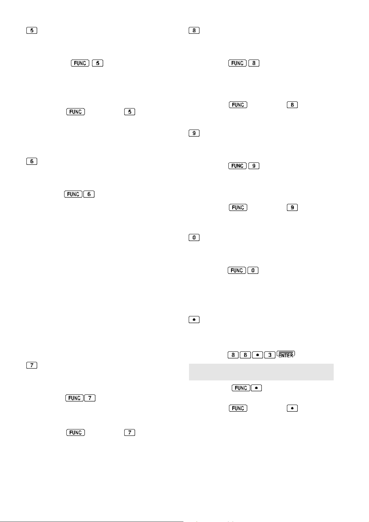
5-15 ACC 2 (accessory 2 socket)
This 8-pin miniature socket is used for connection of an
optional aerial (antenna) switching unit (AS5000) so that
Pin out is as follows:
1 12V 50mA MAX
2 10V 50mA MAX
3 AGC 4.5 ~ 3.0V
4 No connection
5 ANT SW A (data line)
6 ANT SW B (data line)
7 No connection
8 Ground
AR5000 OPERATING MANUAL PAGE 15
Page 16
The control truth table is as follows:
Aerial number 1 3 4
ANT SW A (data) G G
ANT SW B (data) G
Open collector 100mA MAX
(G) connects to ground
5-16 EXT SP - external speaker socket
This 3.5mm mono jack socket provides audio output to
drive an external speaker unit. Connection to this socket
automatically disables the internal speaker but not a
headphone if connected to the front panel socket.
An external speaker should have a nominal 8 OHM
impedance and power handling of 2 WATTS or greater.
5-17 REMOTE - RS232C computer port
The 9 pin female D type RS232C control socket and
associated internal circuitry is fitted as standard. This
permits the AR5000 to be connected directly to a computer
for
hands off
remote control.
must be switched on using the CONFIG menu
,
item three EXT-IF OFF, 1 or 2.
5-19 STD IN (10 MHz)
This BNC socket may be configured using the CONFIG
menu
10 MHz reference (such as off-air atomic coupled).
In the standard configuration, a built-in 12.8 MHz TCXO
is employed.
to accept an external high stability
5-20 MUTE
This PHONO/RCA socket is used to mute the AR5000
when used in conjunction with a transmitter (to mute the
AR5000 when placed into transmit). The transmitter
should provide a normally closed contact becoming open
during transmit.
Note: An internal yellow jumper wire is fitted across the
mute terminals to enable normal operation without the
need for a shorted phono/RCA plug to be fitted in place.
If connected to a transmitter this yellow link wire
be cut. If the receiver is then to be used
shorted plug MUST be left in the mute socket for standard
operation or the AR5000 will not receive and no audio will
be heard from the speaker.
stand alone
must
, a
PC control Windows/95 software is under development
for the AR5000 and a programmer’s RS232 command
protocol supplement is available as an option.
Connection to an IBM compatible PC is as follows:
AR5000 PC 9-pin serial input
2 2
3 3
5 5 (GROUND)
7 7
8 8
AR5000 PC 25-pin serial input
2 3
3 2
5 7 (GROUND)
7 4
In receive mode: Short circuit
In transmit mode (muted): Open circuit
Enabling the mute facility
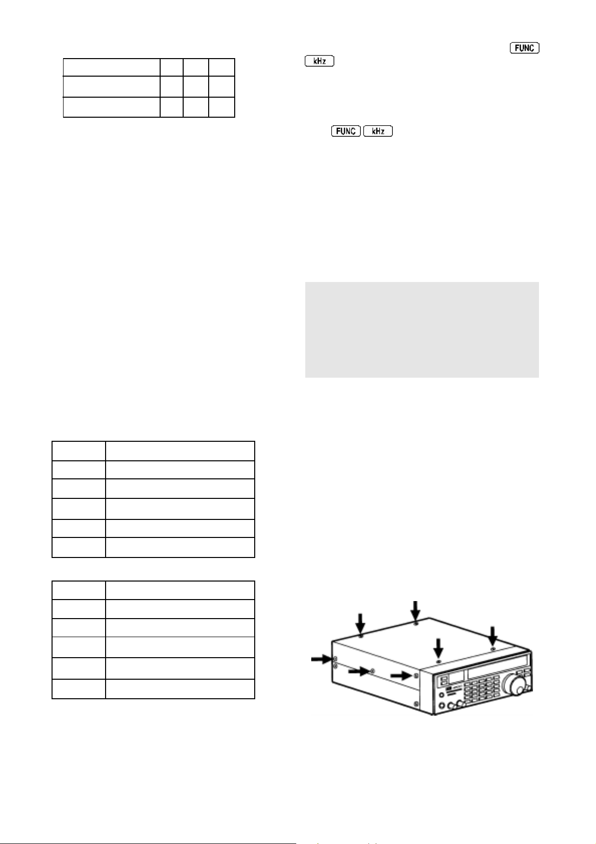
Only the upper case of the AR5000 need by removed to
access the area containing the yellow jumper wire. Switch
the receiver off and unplug the power cord.
1 In order to lift the upper case,
fitting posi-drive screwdriver) remove the 4 screws from
the top cabinet and the 3 screws from each side panel
(the screws on the side of the unit toward the front are
larger than the rest). The rear edge of the top cabinet
has a flange and the sides have two unused holes
(for mobile mounting).
carefully
(with the correct
8 5
5-18 I.F. OUTPUT (10.7 MHz)
This BNC socket provides a suitable output to drive the
optional AOR SDU5000 spectrum display unit providing
a usable ± 5 MHz of bandwidth. The output to this socket
PAGE 16 AR5000 OPERATING MANUAL
2 Locate and cut the yellow jumper wire positioned above
the MUTE terminal.
3 Refit the upper case.
Page 17
5-21 ANT 2
This is the secondary aerial (antenna) input for the AR5000
receiver. It may be controlled from the front panel or
programmed to switch automatically.
The socket is a 50 OHM SO239 type and
the corresponding plug is the PL259. Many off the shelf
inter-series adapters are available for connection to BNC,
N-type or other types of aerial termination.
5-22 ANT 1
This is the primary aerial (antenna) input for the AR5000
receiver. It may be controlled from the front panel or
programmed to switch automatically.
the last right hand digit of the frequency readout (Hz
position) to ensure the receiver is in AUTO MODE. This
places the receiver into a known state of operation ready
to accept frequency input, change of mode etc. As with
all modern microprocessor controlled equipment, the
AR5000 has enormous potential and capabilities.
Note: The AR5000 uses an EEPROM (Electronically
Erasable Programmable Read Only Memory) for storage
of memories and other parameters. A permanent storage
EEPROM has the advantage of not requiring a back-up
battery to maintain data even when the receiver is
disconnected from a power supply. The EEPROM may
be over-written many thousands of times.
6-2 Changing VFO
The socket is a high quality 50 OHM N-type. Many off the
shelf inter-series adapters are available for connection to
BNC, PL259/SO239 or other types of aerial termination.
(6) Basic manual operation of the receiver
To achieve the maximum use of the receiver’s
performance and features, it is important to fully familiarise
yourself with it’s operation through the use of this
handbook.
Connect and select an appropriate aerial (antenna) to the
ANT 1 input on the rear of the receiver. The selection of
aerial depends upon your location and specific
requirements but may include a dipole, discone, colinear
or long wire. There is further aerial information in section
20 of this manual, if in doubt please consult your dealer.
Connect the AR5000 to an appropriate d.c. power source
using either the supplied a.c. adapter or optional DC3000
d.c. lead.
Note: Never connect the AR5000 directly to the
a.c. mains supply.
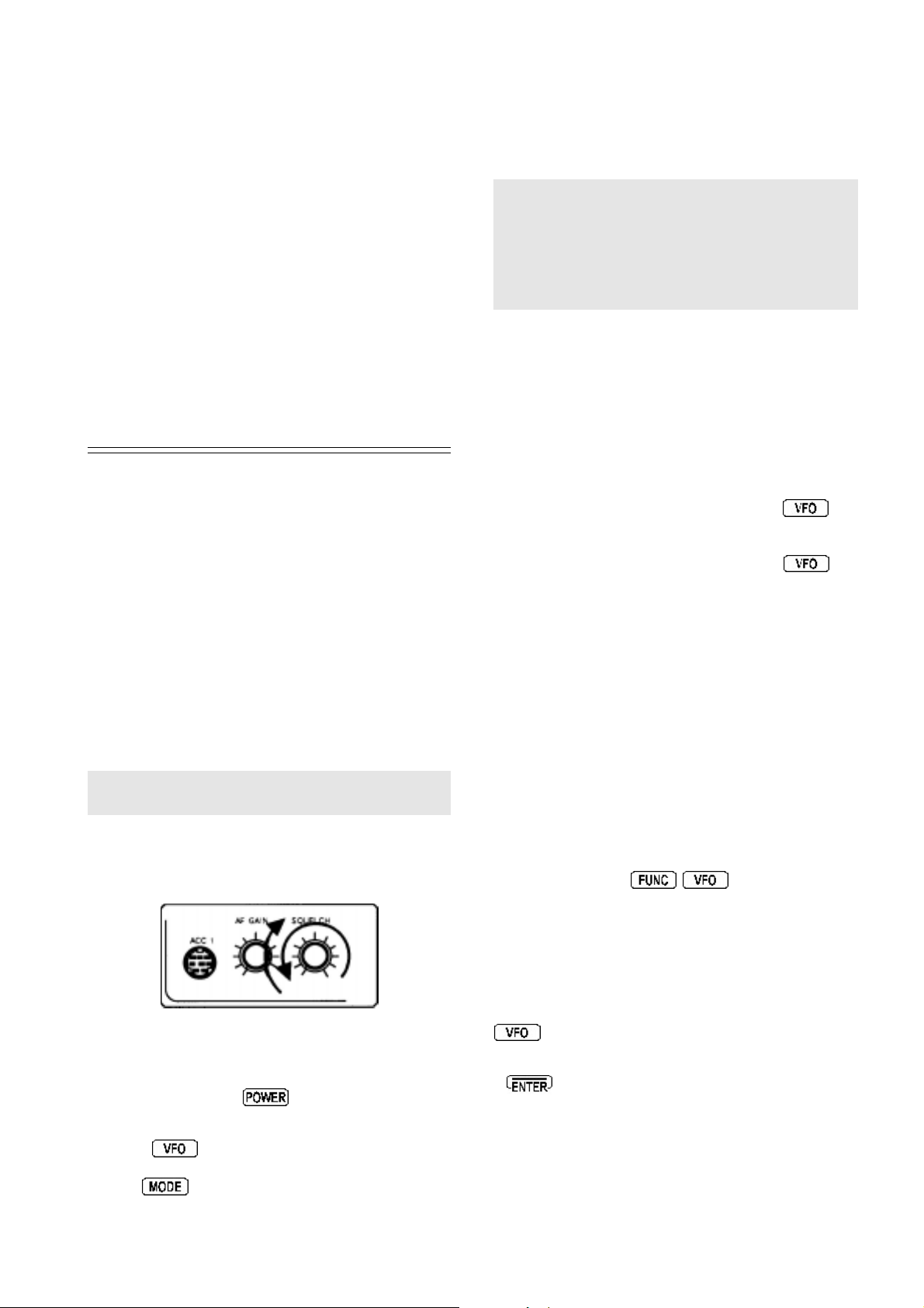
Before turning on the power switch, set the volume to the
10 o’clock position and squelch control to the 12 o’clock
position.
The term VFO historically means
Oscillator
contains frequency, mode, step, and attenuator
information.
The AR5000 has a total of FIVE VFOs which store
frequency , mode, tuning step, I.F. bandwidth, attenuator
setting etc. VFO mode is selected using the
The currently active VFO is displayed in the lower right
corner of the LCD as “VA”, “VB”, “VC”, “VD” and “VE”.
To cycle through the five VFOs, press the
repeatedly until the desired VFO is displayed.
Each VFO can be used for tuning and keying frequencies,
all can hold different parameters. This is useful for keeping
one VFO on VHF airband (AM), one on VHF marine band
(FM), one on 20m amateur band (USB) etc...
In addition, the five VFOs are assigned additional status:
VFO-A
VFO-B Manual search between VFO-A and VFO-B
displayed frequencies
and today refers to a tuneable data store which
Variable Frequency
key .
key
If an automatic frequency search is initiated with “VA” or
“VB” displayed, the process will loop from the start
frequency in VFO-A and search until it gets to VFO-B
then loop back to the start frequency of VFO-A and repeat.
The key sequence
accesses a menu
where the DELA Y , L-SQ level squelch and VOICE options
may be set up for search between VFO-A and VFO-B.
6-1 Switching on for the first time
Press and release the
power up and the LCD back light will illuminate.
Press the
displayed in the lower right corner of the LCD. Press and
hold the
“AUTO” legend is displayed in the centre of the LCD above
key a few times until the legend “VA” is
key for more than one second so that the
switch, the receiver will
VFO-C
VFO-D Accept the frequency from the search mode
If a frequency is keyed in to VFO-C or VFO-D and the
key held for more than one second the search
process will commence from the displayed frequency.
If
is pressed while in SEARCH MODE, the active
frequency will be transferred to VFO-D, the AR5000 will
switch to VFO-D automatically where you may monitor
and tune from the selected frequency.
AR5000 OPERATING MANUAL PAGE 17
Page 18
VFO-E Accept the frequency from the scan mode
If a frequency is keyed in to VFO-E and the key
held for more than one second the search process will
commence from the displayed frequency.
key for more than one second, the “AUTO” legend will
appear on the LCD to confirm selection.
6-4 Entering a frequency via the numeric keypad
If
is pressed while in SCAN MODE, the active
frequency will be transferred to VFO-E, the AR5000 will
switch to VFO-E automatically where you may monitor
and tune from the selected frequency.
Note: If you press the VFO key for one second
or longer, SEARCH will be activated.
6-3 Tuning the receiver using the rotary controls
The receiver may be tuned using the rotary tuning controls
(MAIN DIAL and SUB DIAL) which are used to select receive
frequency and in memory mode for selection of memory
channel etc.
Select VFO mode and the desired VFO out of the five
available “VA”, “VB”, “VC”, “VD” and “ VE”, this achieved
by pressing the
VFO is displayed on the lower right corner of the LCD
(i.e. “VA”).
The AR5000 is now in a known state of operation ready
for data input.
There are two methods of frequency entry , MHz & kHz:
key several times until the desired
MHz
The
in VFO mode. For example to enter a frequency of 88.300
MHz follow the key sequence
There is no need to add the trailing zeros to the right,
once the
microprocessor will automatically add the additional trailing
digits. The display will read “88.300000 MHz”
key is used to enter frequencies as MHz while
key has been used the AR5000
A tuning knob is by far the most
tuning on short wave, the MAIN DIAL provides a smooth
feel and the best method of user interface especially when
listening on the SSB, FAX and CW modes. The SUB DIAL
is indented so tunes in a number of clicks and is best suited
for channelised tuning on the VHF/UHF bands.
It is possible to tune the receiver through it’s entire range
from 10 kHz to 2600 MHz. Rotating the MAIN DIAL &
SUB DIAL clockwise increases the displayed frequency
(and tunes the receiver upward), rotating the controls
anti-clockwise decreases the displayed frequency (and
tunes the receiver downward).
The
decrease the receive frequency .
The AR5000 has an AUTOMODE capability where the
receive mode, frequency step and I.F. filter selection is
made automatically by the AR5000 microprocessor
following detailed bandplan information (for each world
market area). This very much simplifies and speeds up
operation, particularly in the early stages of familiarisation.
When automode is active, the legend “AUTO” is displayed
above the right hand digit (last one, Hz) of frequency
readout. If it is not displayed, press and hold the
keys may also be used to increase or
traditional
approach to
kHz
The
numeric keypad in kHz format. For example: To key in a
frequency of 954 kHz, key
will display “954.000 kHz”. This has the same effect
as keying 0.954MHz or .954MHz (Note: keying a decimal
before the number causes a preceding zero to be
added automatically).
The kHz method of frequency entry reduces the number
of key presses required when working with low frequencies
and simplifies operation as short wave listings are often
stated in kHz. Example: Oceanic air traffic 5616kHz or
short wave transmissions Radio Netherlands 5955kHz and
6045kHz.
Note: Frequencies below 3.0 MHz (3000 kHz) will always
be displayed as kHz regardless of the entry format. It is
usually more convenient to enter medium wave / long wave
frequencies using the kHz format.
key is used to accept frequency input via the
the LCD
PAGE 18 AR5000 OPERATING MANUAL
Page 19
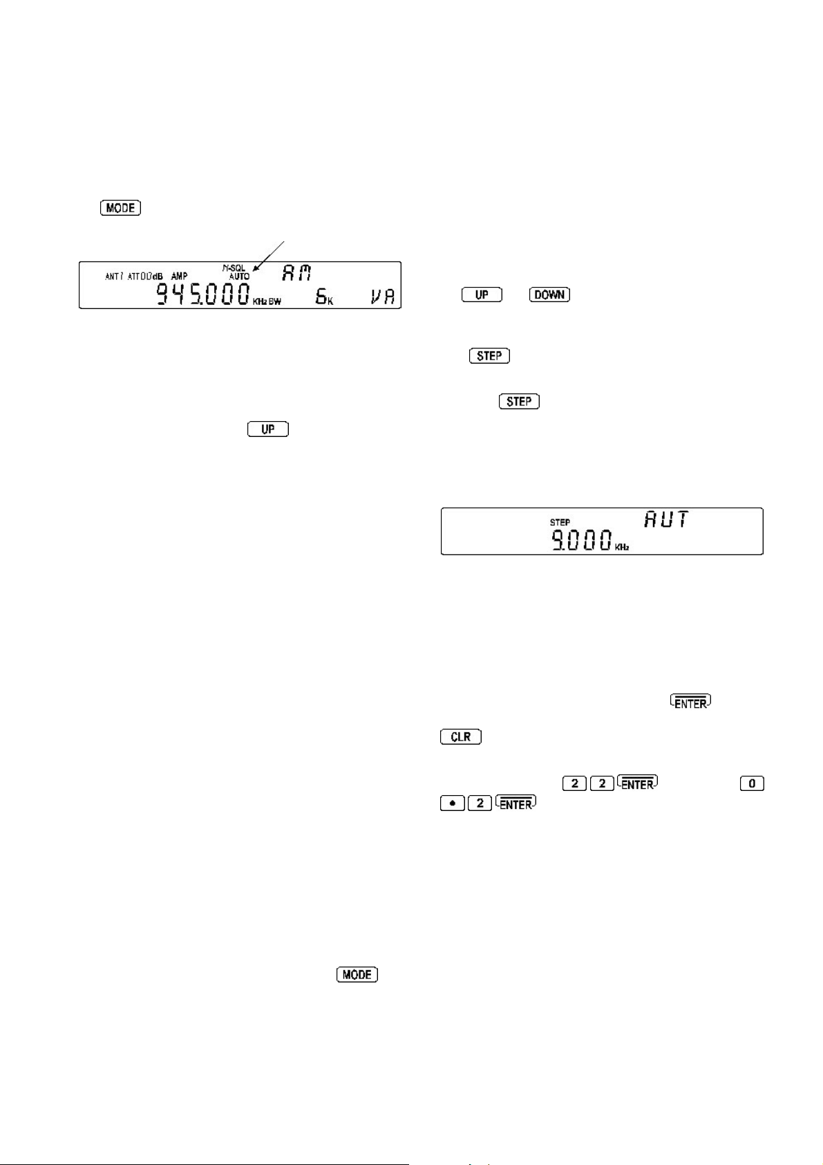
Providing the AUTOMODE facility has been engaged
(so that the “AUTO” legend is displayed above the right
hand digit of frequency readout), you may monitor the
frequency or tune the receiver using the MAIN DIAL or
SUB DIAL. The AR5000 microprocessor will automatically
select the appropriate tuning increment, mode and I.F.
bandwidth from the detailed automode bandplan data
pre-programmed into the receiver (specific to each world
market area). If automode is not active, press and hold
the
legend on the LCD will confirm operation.
key for more than one second. The “AUTO”
Most known step sizes are available with the exceptions
such as TV channels which are allocated with 6MHz or
4MHz spacing. There will be occasions when you may
wish to change the automode step selection so it is
possible to customise the step size used by the MAIN DIAL
and SUB DIAL (step size may also be programmed in search
mode).
MAIN DIAL
Only when the VFO mode is engaged may the MAIN DIAL
be used to select the receive frequency. Rotate the
MAIN DIAL to change the receive frequency, alternatively
the
step in the pre-programmed step size as dictated by the
automode bandplan data.
and
keys can be used. Frequency will
6-5 Correction of frequency during input via
the numeric keypad
Should a mistake be made while entering frequency via
the keypad in VFO mode, the
backspace delete the entry from the right hand side. If all
digits are deleted, the display will return to the previous
frequency.
key may be used to
6-6 Selecting tuning step (increment)
The specification for channel occupancy , step (separation)
and mode are decided by and allocated by departments
of Government following International discussions.
Not surprisingly the allocation of frequency bands are not
the same all over the world and channel separation (step)
varies from band to band. As an example, the channel
separation (step) for the medium wave band in Europe is
9 kHz while in the U.S.A. it is 10 kHz.
For the above reason it is necessary to alter the STEP
size according to local bandplan conventions. The
AR5000 has been pre-programmed at the factory with all
the bandplan data (specific to each market area) so that
the AR5000 will automatically select the appropriate step
size and mode for the frequency chosen. This greatly
simplifies operation of the receiver while you are
familiarising yourself with all the facilities.
The pre-programming of step size may be manually
overridden so you may choose alternative settings at will
or when bandplans are updated.
The tuning step (often referred to as the tuning rate or
increment) is usually automatically set by the AR5000
using the automode bandplan information - WHEN
AUTOMODE IS ENGAGED.
To enable AUT OMODE, press and hold the
for more than one second, the “AUTO” legend will
appear on the LCD above the right hand (last) digit of
the frequency readout to confirm selection.
key
The
receiver to be customised.
Press the
LCD confirms that the STEP SELECT MENU has been
activated. If the legend ”AUT” is displayed above-right,
then the step will automatically be determined from the
automode bandplan data. As soon as another selection
is made automode is cancelled.
At this point the SUB DIAL may be rotated to select a new
step size for the MAIN DIAL from the following list: 0.001
kHz (1 Hz), 0.010 kHz (10 Hz), 0.050 kHz (50 Hz), 0.100
kHz (100 Hz), 0.500 kHz (500 Hz), 1.000 kHz, 5.000kHz,
6.250 kHz, 9.000 kHz, 10.000 kHz, 12.500 kHz, 20.000
kHz, 25.000 kHz, 30.000 kHz, 50.000 kHz, 100.000 kHz
and 500 kHz.
Once the selection has been made press
any changes. If you wish to abort step size selection press
In addition, unusual step sizes may be entered using the
numeric keypad (i.e.
1 Hz to 999.999 kHz.
Important: The receive frequency must be divisible by
the step size or the receiver will not receive the desired
frequency or follow the bandplan.
Examples:
Receive frequency / Step size
433.200MHz/20kHz = Divisible (433200 / 20 = 21660 all okay)
152.010MHz/20kHz = Not divisible (152010 / 20 = 7600.5 so must
key enables the step size for tuning the
key , the flashing legend “STEP” on the
to accept
for 200 Hz). Acceptable input range is
for 22 kHz or
must = round number
use the special STEP-ADJUST
FACILITY detailed section 6-7
of this manual).
AR5000 OPERATING MANUAL PAGE 19
Page 20
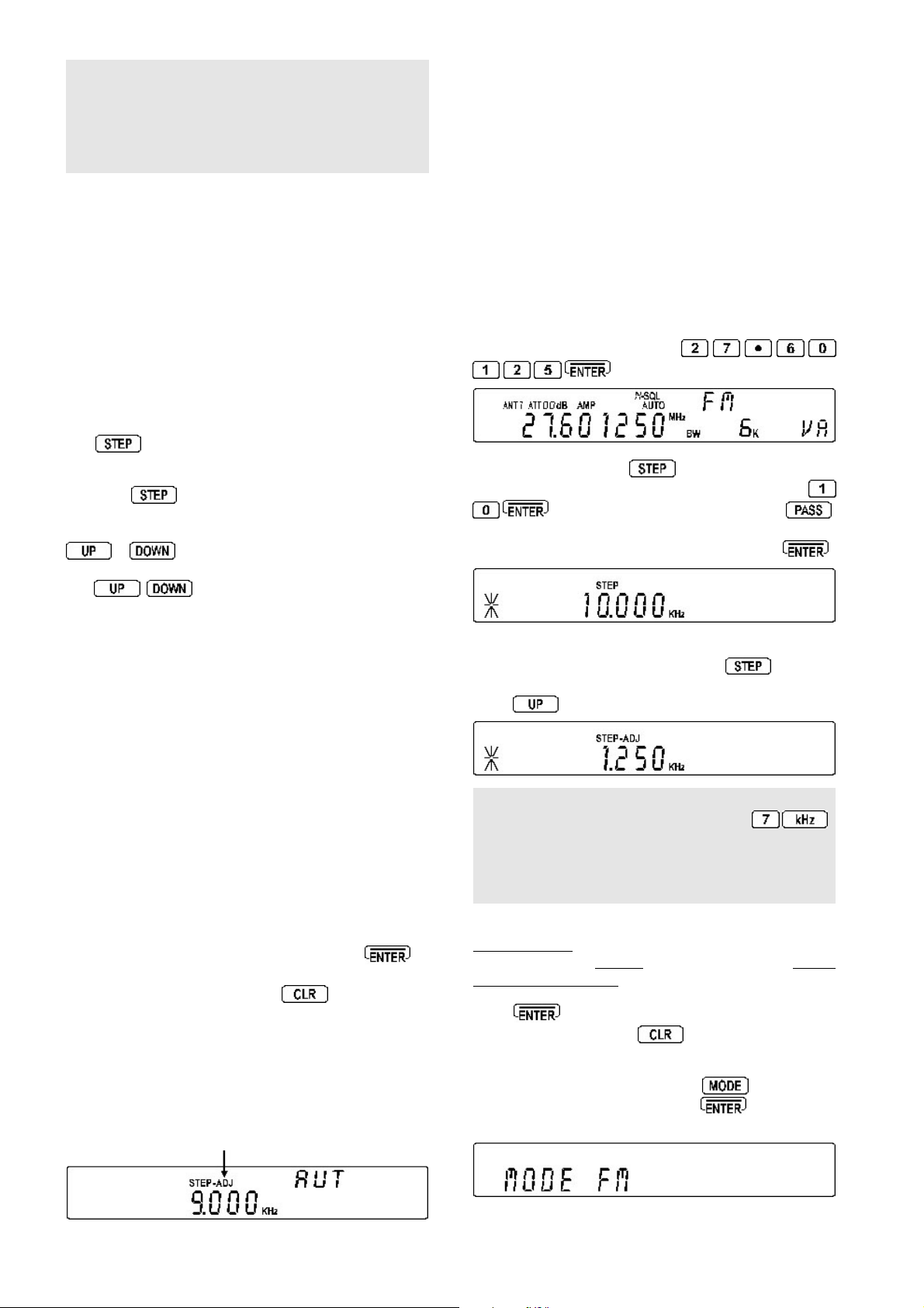
Note: The MAIN DIAL is a mechanical encoder and as
such small variations in tuning may be experienced or the
frequency may move slightly after rotation, this is normal.
To ensure the best life span and smoothest operation,
rotate the control from time to time to ensure the encoder’s
track remains clean.
SUB DIAL
Step-adjust is used when the receiving frequency is not
divisible by the step size in use (It is possible that stepadjust has been programmed into the automode bandplan
data for some world market areas). Therefore step-adjust
is useful for certain bandplans such as cellular which in
some areas starts as 917.0125 MHz then increments in
25 kHz steps. Another example is the CB allocation in
certain areas which starts at 27.60125 MHz then
increments in 10 kHz steps.
The SUB DIAL can also be used to select the receive
frequency in three different ways:
l Same step size as the MAIN DIAL
l 10 times faster than the MAIN DIAL
l One of the step sizes from 0.1 kHz (100 Hz),
0.5 kHz (500 Hz), 1.0 kHz, 5.0 kHz, 10.0 kHz,
50.0 kHz, 100.0 kHz, 500.0 kHz or 1000.0
kHz (1 MHz).
The
be selected.
Press the
LCD confirms that the STEP SELECT MENU has been
activated. The first menu is for the MAIN DIAL so press
(if step adjust is in use the legend “*” will be displayed and
the
increment to the SUB DIAL menu). The flashing legends on
the LCD “STEP” and “SUB” indicate that the SUB DIAL
step selection menu has been activated. Use the
SUB DIAL to make selection:
key enables the step size for the SUB DIAL to
key , the flashing legend “STEP” on the
or
SUB MAIN
SUB x 10
SUB 0.1 kHz
to move on to the SUB DIAL configuration
keys will require two presses to
Example:
Tune through the UK CB frequencies of 27.60125 MHz in
10 kHz steps with mode set to FM, 15 kHz bandwidth.
Select frequency: Select the start frequency for tuning,
in this example 27.60125 MHz
Set up step: Press the
step menu. Select a step size of 10 kHz by pressing
the “*” legend is displayed on the left of the LCD to confirm
operation. Complete the sequence by pressing
You may review or change the
step-adjust via the STEP menu. Press
the tuning step menu. Initially the
press
. Select STEP-ADJUST by pressing
to view the
STEP-ADJUST
key to access the tuning
offset
step
value used by
to access
size is displayed,
value.
,
.
MAIN = tuning rate for the SUB DIAL will be the same as
that of the MAIN DIAL.
x10 = tuning rate of the SUB DIAL will be ten times faster
than the MAIN DIAL (i.e. a tuning rate on the MAIN DIAL of
25 kHz will be 250 kHz on the SUB DIAL).
0.1 kHz (100 Hz), 0.5 kHz (500 Hz), 1.0 kHz, 5.0 kHz,
10.0 kHz, 50.0 kHz, 100.0 kHz, 500.0 kHz, 1000.0 kHz
(1 MHz) = tuning rates for SUB DIAL.
When the selection has been made, press
accept the changes and return to VFO mode. If you wish
to abort step size selection press
to
6-7 Step-adjust
The AR5000 provides a powerful feature to enable
accurate following of unusual bandplans. When active,
the “STEP-ADJ” legend is displayed in the centre of the
LCD.
Note: It is possible to enter a new value of step-adjust
using the
SUB DIAL
and numeric keypad (i.e.
)
while viewing the step-adjust value, you can experiment
with interesting results! If you intend direct programming
please refer to the mathematical explanation at the end
of this section 6-7.
Half step:
If the original tuned frequency were a
round number such as 145.000 MHz with a step size
of say 25 kHz, the default step-adjust would be half of
the original step size (12.5 kHz).
Press to accept the data input and return to VFO
mode. Alternatively press
to VFO mode.
Select receive mode: Press the
the SUB DIAL to select “FM”. Press
selection and return to VFO mode.
to abort entry and return
key and use
to accept the
PAGE 20 AR5000 OPERATING MANUAL
Page 21
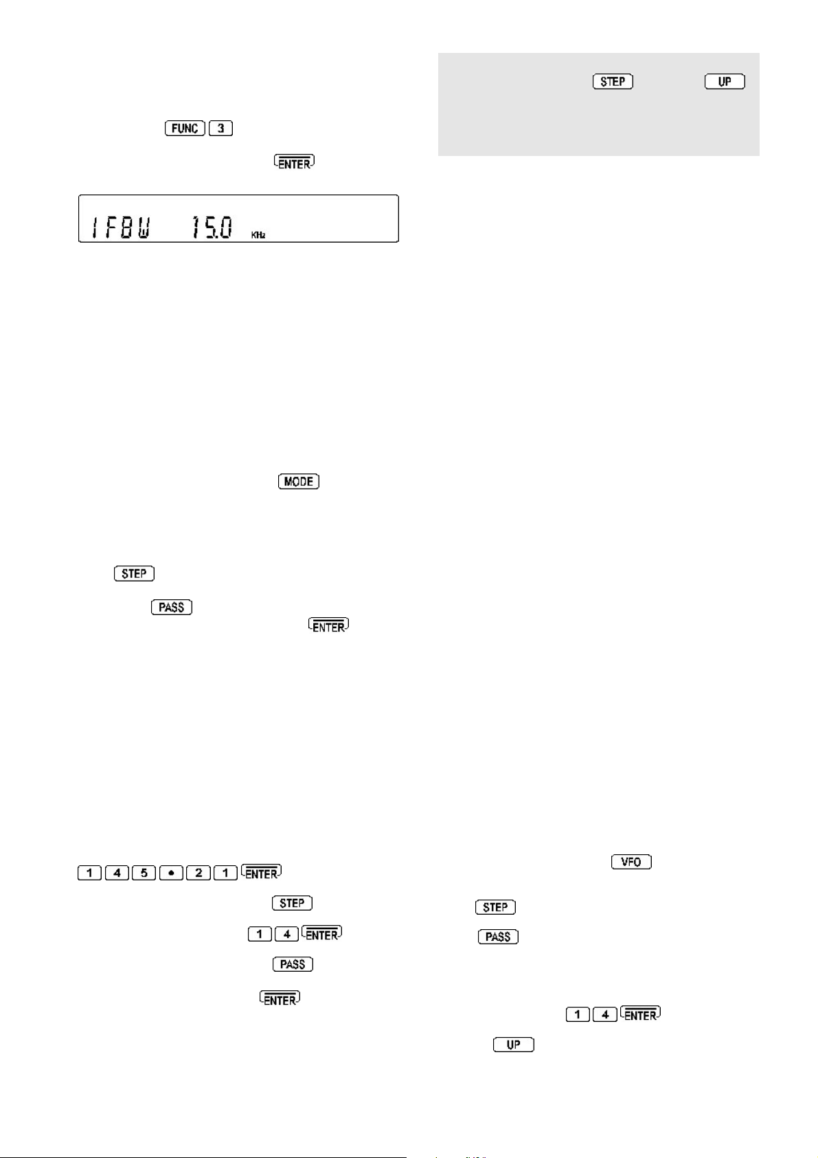
Select receive bandwidth: For point-to-point
communications a bandwidth of 15 kHz usually provides
best results, however if adjacent channel interference is
experienced a bandwidth of 6 kHz may provide better
results. Press
menu then use the SUB DIAL to make the selection (in this
example select 15 kHz). Press
selection and return to VFO mode.
If the MAIN DIAL is rotated the frequency will increment in
10 kHz steps but the trailing 1.25 kHz will remain in place...
27.60125 MHz, 27.61125 MHz, 27.62125 MHz etc.
The trailing digits will not be set to zero enabling tracking
of unusual band plans.
The
MAIN DIAL
bandplan while the
t
o access the I.F. bandwidth
to accept the
follows the adjusted frequency
SUB DIAL
kills the trailing digits
and steps rigorously in round numbers.
To cancel step-adjust
The easiest way to cancel step-adjust is to return to
AUTOMODE, press and hold the
than one second. Step-adjust will be cancelled and the
frequency will hop to the nearest whole increment as
determined by the automode bandplan data.
Y ou may also cancel step-adjust using the STEP MENU.
Press
active, the legend “*” will be displayed on the left of the
LCD. Press
Off. T o accept the change to OFF, press
to VFO mode.
to activate the step menu. If step-adjust is
to toggle the step-adjust facility On/
key for more
to return
Note: Y ou may review the step-adjust value quite simply ...
While in VFO mode, press
access the step-adjust sub menu. In the above example
the step-adjust value will be 2.0 kHz, refer to the following
text for the mathematical explanation...
followed by
to
this is not
essential but makes good bedtime reading!!!
Application of arithmetic for the step-adjust
For those who wish further information on the
mathematics involved... the AR5000 works this out for
you automatically! The following examples should explain
how the step-adjust works in theory.
If the frequencies you need to search are allocated as:
145.210 145.224 145.238 145.252 145.266 145.280
145.294 145.308 (MHz)
Check the stepping size at first:
145.224 - 145.210 = 0.014 STEP SIZE (MHz)
Now you have found that each frequency is allocated
with a 0.014 MHz (14kHz) spacing you now have to
calculate the value of the internal processing frequency:
145.210 / 0.014 = 10372.14285
This should be rounded as 10372 INTERNAL
PROCESSING VALUE
To obtain the internal processing frequency, multiply the
STEP SIZE by the INTERNAL PROCESSING VALUE:
0.014 x 10372 = 145.208 INTERNAL PROCESSING
FREQUENCY (in MHz).
Now calculate the STEP-ADJUST VALUE by subtracting
the INTERNAL PROCESSING FREQUENCY from the
DESIRED FREQUENCY:
Another example:
If the frequencies you need to search are allocated as:
145.210 145.224 145.238 145.252 145.266 145.280
145.294 145.308
Check the stepping size at first:
145.224 - 145.210 = 0.014 STEP SIZE
T o enter this step size and data using the
First key in the start frequency while in VFO mode:
Select the step menu by pressing
Key in the required step size:
Select
step-adjust
“*” appears on the left of the LCD to confirm selection.
Complete the entry by pressing
The MAIN DIAL will now tune the receiver in 14 kHz steps
with the trailing offset maintained. The SUB DIAL tunes the
receiver in 14 kHz steps but clears the offset to a round
number (i.e. zero).
by pressing the key , the legend
easiest
method!
145.210 - 145.208 = 0.002 (MHz) = 2 kHz
STEP-ADJUST VALUE
It can be concluded that a step-adjust value of 2 kHz is
required.
In order to step through the above frequency
allocation you need to apply a STEP SIZE OF 14 kHz
with a 2 kHz STEP-ADJUST.
To apply a step size of 14 kHz and step-adjust of 2kHz:
Select VFO mode by pressing
, select the desired
VFO (displayed in the right hand lower corner of the LCD).
Press
Press
to activate the STEP select menu.
to select STEP-ADJUST. The legend
“*” will appear on the left of the display to confirm selection
of step-adjust.
Key in the required step size for tuning (14 kHz in this
example) by pressing
Press the
key to select the step-adjust entry menu.
The “STEP-ADJ” legend will flash in the middle of the
AR5000 OPERATING MANUAL PAGE 21
Page 22
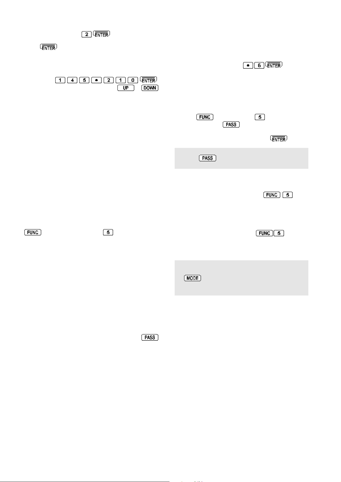
LCD inviting you to enter the value for step-adjust (2 kHz
in the example). Press
Press once more to return to VFO mode. You
will note the static legend “STEP-ADJ” to confirm that
step-adjust is in operation.
Key in the start frequency (145.210 MHz in this example)
by pressing
Change frequency using the
MAIN DIAL
,
or
.
keys to confirm correct operation.
6-8 FREQUENCY OFFSET
This facility enables receive frequency to be quickly
SHIFTED (two key presses) by pre-determined margin,
which makes it easy to track duplex-transmissions or check
repeater inputs / outputs.
Offset frequencies may be factory pre-programmed into
the automode bandplan data for some world market areas.
Frequency offset may also be programmed manually.
Setting up an OFFSET FREQUENCY
Before the FREQUENCY OFFSET facility can be used,
it first needs to be configured (unless factory programmed
for certain bands).
1. To activate the frequency offset set-up menu press
then press and hold the
one second.
Example of display:
OFF
+ 45.000000 02
+ 0.600000 01
Offset frequency can be selected between the ranges of
0 to 999.999999 MHz and OFF. Available offset
frequencies can be allocated into special storage locations
numbered from 01 to 47. Number 00 is always treated
as OFF and cannot be overwritten.
Locations 20 to 47 are reserved for factory preprogramming. These locations may be recalled and the
positive / negative frequency shift altered using the
key but new numeric frequency offsets may not be stored.
Locations 01 to 19 are available for the operator to store
new frequency offsets.
key for more than
2. While the “FR-OFS” legend is flashing on the display
to indicate that the frequency offset menu has been
selected, rotate the SUB DIAL to select a new (blank) location
(i.e. 02).
3. Enter the offset frequency via the numeric keypad in
MHz (i.e. for 600 kHz press
will return to VFO, MEMORY, SCAN or SEARCH mode,
whichever was previously in use.
4. If editing a previously stored offset frequency it is
possible to select whether the offset should be up (+) or
down (-) from the displayed frequency. If the frequency
entered was new, simply re-enter the setup mode by
pressing
one second. Press
offset either “+” or “-”, confirmation will be displayed on
the LCD. To accept any changes press
Note: The direction of frequency offset “+” or “-” selected
using the
locations. The default is “+”.
Activating frequency offset
To activate frequency offset press
legend “FR-OFS” will be displayed on the LCD above the
“MHz” legend to confirm operation. The displayed receive
frequency will change to reflect the offset value and the
receiver will monitor the new displayed frequency .
T o deactivate frequency offset key
“FR-OFS” legend will be removed from the LCD and the
receiver will revert to the original frequency. See above
(item 4) for selection of “+” or “-” offset.
Note: The use of frequency offset will take the AR5000
out of automode. T o reactivate automode press and hold
the
“AUTO” appears on the LCD to confirm that automode
has been reactivated.
Frequency offset with memory channels
All of the above may appear rather long-winded, however
the facility comes into its own when the frequency offset
is stored into memory along with other data such as receive
frequency, mode etc during normal memory write (see
section 7 of this manual), no special sequence is required.
When written to memory both the frequency offset and
direction of offset are stored for quick recall.
then holding the
key has global effect on all OFFSET
key for more than one second, the legend
to toggle the direction of the
. The LCD
key for more than
. The
again, the
00 OFF
01 ~ 19 Available for storage of new offsets
20 ~ 47 Reserved for factory pre-programming
Having a number of frequency offset set-ups programmed
ready for retrieval makes the facility even more useful
when changing between frequency bands which have
different duplex or repeater frequency offsets.
PAGE 22 AR5000 OPERATING MANUAL
6-9 Changing receive mode (AUTOMODE)
As mentioned earlier in this manual, the specification for
step and mode are allocated by departments of
Government following International discussions. Like step
size, the receive mode has been pre-programmed at the
factory to simplify operation of the receiver while you
familiarise yourself with all the facilities.
Should you wish, the defaults may be manually overridden
at any time so that an alternative receive mode can be
Page 23
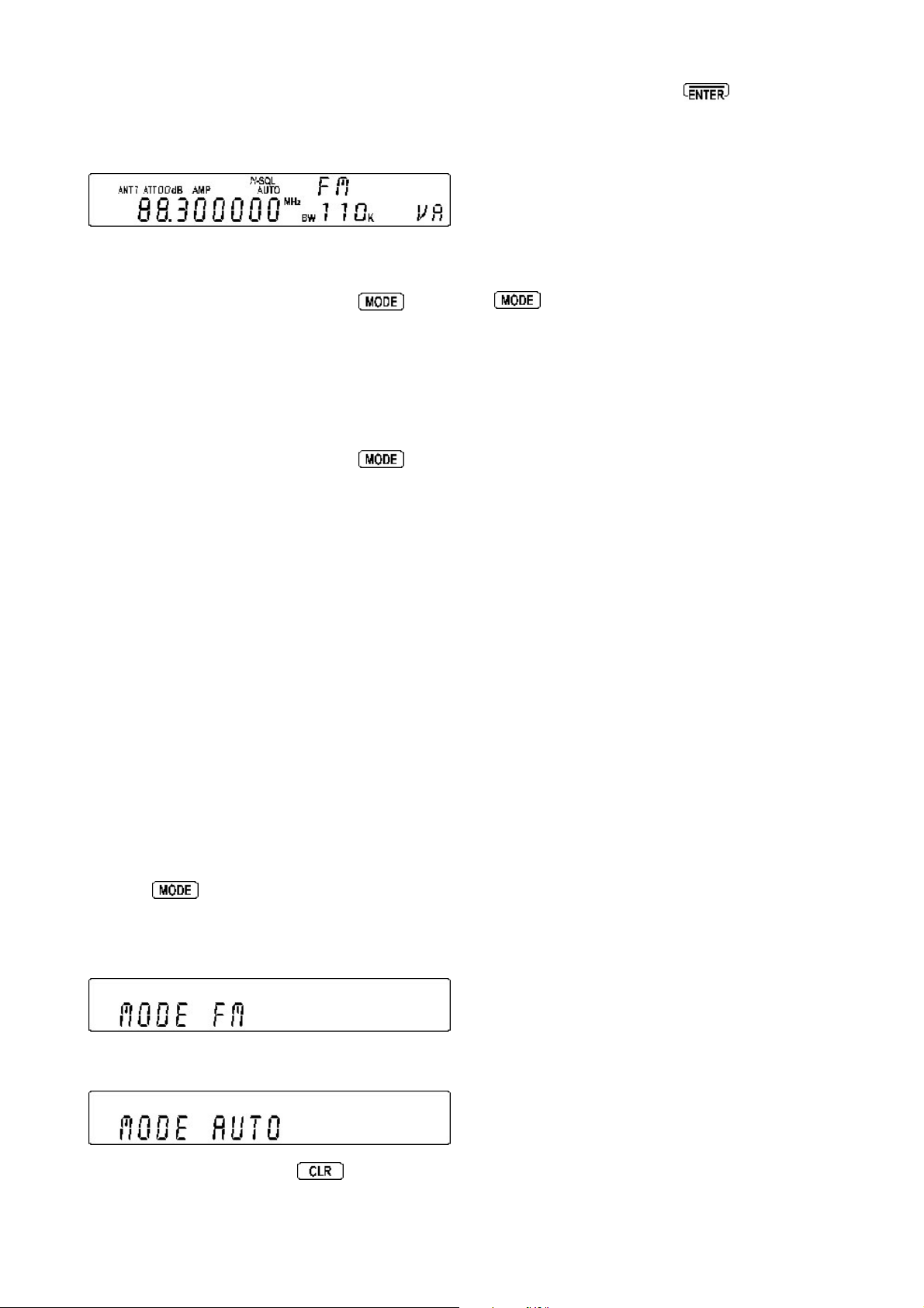
used on any frequency within the set’s range.
In normal operation AUTOMODE should be used. The
legend “AUTO” is displayed above the right hand (last)
digit of the frequency readout when automode is in
operation.
Activating AUTOMODE
To activate automode, press and hold the
more than one second. The receive mode, I.F. filter
bandwidth, step, step-adjust and frequency offset will then
be automatically read from the automode bandplan data
pre-programmed at the factory for each specific world
market area.
key for
The SUB DIAL is used to change mode. When you have
made your selection, press
mode. The display will revert to VFO mode and the
AR5000 will receive in the selected receive mode.
Automode will have been cancelled and the “AUTO”
legend will not be displayed on the LCD.
Each of the five VFOs (“VA”, “VB”, “VC”, “VD”, “VE”)
can hold different modes, it is suggested that one be left
on AUTOMODE for general tuning and others set to
specific modes for specialist listening applications.
to accept the new
Remember: To reinstate automode press and hold the
key for more than one second.
Although any receive mode may be selected at any
frequency within the receiver’s frequency coverage,
generally speaking the following modes will apply:
Manually changing any of the parameters held by the
automode bandplan data will cancel automode operation.
T o reinstate automode press and hold the
more than one second again.
Selecting automode will cancel any user defined items
from the following list and select them automatically from
the AR5000 bandplan data:
key for
w Receive mode
w Offset frequency
w IFBW
w LPF
w HPF
w De-emphasis
w Tuning step
w Step-adjust
w AGC
The automode bandplan information can only be
programmed at the factory or via a specialised computer
program.
Manually changing receive mode
To change receive mode and override automode, briefly
press the
the LCD to confirm that the mode select menu has been
activated. The following modes are available from the
MODE menu: “AUTO”, “FM”, “AM”, “LSB”, “USB” and
“CW”.
key. The “MODE” legend will flash on
AM
Amplitude Modulation - Used by broadcast services
throughout the world on long wave, medium wave and
short wave. AM is also used by VHF civil airband, UHF
military airband and some PMR (Private Mobile Radio)
and utility services.
FM
There are two common types of FM (Frequency
Modulation), these are:
NFM - Narrow Band Frequency Modulation - this provides
high quality communication for relatively short distance
operation. FM uses a greater frequency bandwidth than
other modes such as SSB so is less efficient.
NFM is the most common mode used above 30 MHz with
the exception of the airbands. NFM is widely used on the
VHF bands: VHF marine band, 2m amateur band
(145MHz), 70cm amateur band (433 MHz), PMR (Private
Mobile Radio) and utilities.
In the absence of a signal, the background white noise
may appear quite loud. For ease of listening, the squelch
control should be rotated clockwise until the background
noise just disappears, this should be carried out while no
signal is present. The point where the background noise
is cancelled is known as
the squelch control more than necessary or the receiver
will appear to be desensitised and weaker signals will be
missed.
threshold point
. Do not advance
If automode is currently in use, the legend “AUTO” will
be displayed on the LCD.
To escape from the menu press
WFM - The AR5000 does not list WFM (Wide Band
Frequency Modulation) as a separate mode, it is simply a
product of the I.F . filter bandwidth selection. Select a wide
filter such as 100 kHz or 220 kHz and the receiver will
use WFM.
Wide Band Frequency Modulation - used by VHF and
UHF broadcast stations as excellent audio quality is
available due to the relatively wide frequency bandwidth
employed. Used only for local services such as VHF
Band-II stereo (received as mono on the AR5000) and
UHF TV sound channels.
AR5000 OPERATING MANUAL PAGE 23
Page 24

LSB
Lower Side Band - is a form of Single Side Band (SSB).
LSB tends
used by Radio Amateurs on frequencies below 10 MHz.
This assists the separation of Commercial and Amateur
users on traditionally shared bands and prevents them
from speaking to each other.
SSB is a very efficient method of transmission as the
unwanted second sideband and carrier have been
removed. This allows the full transmitter power to be
employed in carrying useful information within the wanted
sideband. As a result, greater distances are possible on
SSB and a smaller frequency bandwidth is required than
most other modes.
The AR5000 uses true carrier re-insertion and a dedicated
SSB I.F . filter so that voice becomes intelligible. However
due to the complexities of SSB, audio never sounds 100%
natural and often listeners comment on it sounding a little
like
with practice you soon become used to this characteristic.
This is not a criticism of the AR5000 and is applicable to
ALL SSB receivers in varying degrees... the AR5000
being very good.
Small tuning steps of 10 Hz (or 100 Hz at most) should
be used for tuning in LSB and other similar modes USB &
CW.
The SSB frequency display is not offset (like some other
units). However being such a compact wide band receiver,
it will not be unusual for the SSB display to be very slightly
off frequency when listening to known frequencies such
as VOLMET (airband weather forecast service).
not
to be used commercially but is extensively
Donald Duck
or
Micky Mouse
but this is normal and
In FM mode the options are AGC ON / OFF and in other
modes are OFF , F AST, MIDDLE and SLOW. When AGC
OFF has been selected, two horizontal bars “=“ are
displayed on the LCD between the kHz and MHz legends.
FM: AGC OFF
AGC ON
Other modes: AGC OFF
AGC FAST
AGC MIDDLE
AGC SLOW
Note: “AUT” for AUTO AGC will be displayed toward
the top right of the LCD if AUTOMODE is in operation,
the appropriate AGC selection will be made automatically
by the AR5000.
6-10 IF BANDWIDTH
The I.F . bandwidth selects how SELECTIVE the receiver
will be when monitoring signals off air . However it is not
simply a case of using the narrowest filter at all times,
particular modes require differing amounts of bandwidth
in order to operate otherwise the receive system simply
will not produce intelligible sound!
Correct receive mode and IF bandwidth must always be
selected for optimum reception. If the bandwidth selection
is too narrow, distortion or signal break-up may occur. If
the bandwidth selection is too wide, adjacent interference
may be encountered.
For this reason, a selection of I.F. filter bandwidths are
fitted as standard. Typical examples of receive mode and
IF bandwidth are:
USB
Upper Side Band - The same comments apply as for
LSB. By convention, Radio Amateurs also use USB above
10MHz.
All long range shipping and oceanic air traffic (as well as
long range military aircraft) use USB. DATA modes such
as RTTY, SITOR, PACKET, FAX etc may be resolved
using USB.
CW
Continuous Wave - Often referred to as Carrier Wave or
Morse code (
short wave bands by radio amateurs toward the lower
end of each band allocation. Some commercial use is
still made by shipping etc although its use is being phased
out due to the introduction of automated stations. The
AR5000 has the provision for the operator to select the
frequency offset used by the receiver in CW mode using
the AF.SET menu.
Note about AGC (Automatic Gain Control)
If the AGC is not set appropriately, audio will sound
distorted. The key sequence
AGC menu.
dots and dashes)
. Commonly used on the
activates the
FM 220kHz VHF FM broadcast (110k may also be
used - mono only)
FM 110kHz TV audio (also VHF FM broadcast - in
mono only)
FM 100 or 30kHz Wireless mic, etc (30kHz for
satellite FAX too)
FM 15kHz PMR, amateur band etc FM 6 kHz may
also be used
AM 6kHz VHF / UHF airband, short wave broadcast,
medium & long wave, PMR etc
USB/LSB 3kHz Short wave amateur band, short wave
utility such as oceanic airband etc
CW 3kHz (0.5kHz with optional filter fitted). Morse
code used by radio amateurs and some
marine traffic on short wave
An appropriate IF filter is automatically selected when
automode is engaged. However any combination of IF
filter and receive mode is possible in the MANUAL MODE.
When you have manually selected an IF filter bandwidth,
AUTOMODE will be disengaged, but the receive mode,
stepping size, etc will be retained until they are changed
manually .
PAGE 24 AR5000 OPERATING MANUAL
Page 25

Manually selecting I.F . bandwidth.
1 Audio Low Pass Filter
The sequence
activates the I.F. bandwidth
menu.
In normal operation the word “AUT” will be displayed in
the upper right of the LCD to signify that automode is in
operation and the I.F. bandwidth, receive mode and
channel step will be automatically selected by the AR5000
from its detailed pre-programmed bandplan data.
Selecting a new bandwidth from the list of 220, 110, 30,
15, 6 and 3 kHz is accomplished using the SUB DIAL, 0.5
kHz is only available if the optional CW filter has been
fitted. To accept the new bandwidth selection press
Once automode has been cancelled, it may be reinstated
from the MODE select menu or by pressing and holding
the
key for more than one second.
I.F . filter bandwidth table:
Filter kHz Total nose Total skirt
(b’width kHz / dB)
0.5(500Hz) opt 0.5 -3 2.0 -60
2.5 opt 2.5 -3 5.2 -60
3 2.4 -6 4.5 -60
5.5 opt 5.5 -3 11.0 -60
6 9.0 -6 20 -50
The audio low pass filter is useful to cut off high tones
(allowing low tones to pass) to improve intelligibility of weak
signals in close proximity to adjacent interference and to
remove
hiss
making listening for extended periods easier
on the ears.
There are four available cut off frequencies: 3.0 kHz,
4.0kHz, 6.0kHz & 12.0 kHz. The lower the frequency the
more limited the audio bandwidth... for highest fidelity for
Band-II listening select 12.0 kHz. If the filter selection has
been left to automode, the legend “AUT” will be displayed.
The audio low pass filter will initially be automatically
selected according to the IF bandwidth:
Bandwidth Audio Low Pass Filter
0.5 kHz to 15 kHz 3.0 kHz
Above 30 kHz 12.0 kHz
The audio low pass filter selection is accessed via a
sub menu.
A-LPF 3.0 kHz <<<
A-HPF 0.05 kHz
DE.EMP 750
CW.PITCH 0.7 kHz
AUDIO INT
1. Press
.
The LCD will show, for example,
“A-LPF 3.0 kHz”.
2. Rotate the SUB DIAL to make selection: 3.0 kHz, 4.0kHz,
6.0kHz or 12.0kHz.
15 15 -6 30 -50
30 30 -6 70 -50
110 140 -3 350 -20
220 260 -3 520 -20
6-11 AF SET - (Audio characteristics)
It is possible to optimise the audio settings of the AR5000,
there are a total of 5 different settings relating to the audio
characteristics:
1) Low pass filter A-LPF 3.0 kHz
2) High pass filter A-HPF 0.3 kHz
3) De-emphasis DE.EMP 750
4) CW pitch CW.PITCH 0.7 kHz
5) Input switching AUDIO INT
3. Press
or
to accept the changes,
to move on to the audio high pass filter selection.
to abort
2 Audio High Pass Filter
The audio high pass filter is useful for limiting the audio
bass response (allowing higher tones to pass) improving
intelligibility in certain circumstances (such as low
frequency whistles on AM, SSB & CW).
There are four available high pass frequencies: 0.05 kHz
(50 Hz), 0.02 kHz (200 Hz), 0.3kHz (300 Hz) & 0.4 kHz
(400 Hz). The higher the frequency the more limited the
audio bandwidth... for highest fidelity for Band-II VFO
listening select 0.05 kHz. If the filter selection has been
set to automode, the legend “AUT” will be displayed.
The audio high pass filter will initially be automatically
selected according to the IF bandwidth:
Bandwidth Audio High Pass Filter
0.5 kHz to 15 kHz 0.3 kHz (300 Hz)
Above 30 kHz 0.05 kHz (50 Hz)
AR5000 OPERATING MANUAL PAGE 25
Page 26

The audio high pass filter selection is accessed via a
sub menu.
A-LPF 3.0 kHz
A-HPF 0.05 kHz <<<
DE.EMP 750
CW.PITCH 0.7 kHz
AUDIO INT
1. Press
low pass filter selection, press the
. The LCD will first display the
key to access
the high pass filter sub menu.
2. Rotate the SUB DIAL to make selection: 0.05 kHz,
0.2 kHz, 0.3 kHz or 0.4 kHz.
3. Press
or
to accept the changes,
to move on to the audio de-emphasis selection.
to abort
3 Audio De-emphasis
This is really only applicable to FM mode and affects the
sharpness
of recovered audio. Band-II transmissions in
different world areas have different defaults for deemphasis, if for instance a value of 750 is selected in
Europe the recovered audio will sound very
muffled
.
The available range is as follows:
THRU, 25uS, 50uS, 75uS & 750uS
The audio de-emphasis will initially be automatically
selected according to the IF bandwidth:
Bandwidth Receive Mode De-emphasis
0.5k to 15 kHz FM 750uS
4 CW Pitch
Comfortable listening to CW (Continuous Wave, often
referred to as Morse code) is usually centred around a
tone
of 700 to 800 Hz. The audio stage of the AR5000 is
configured to emphasise this
window
, however the centre
frequency may be changed to suit personal preferences
or specific requirements. This function is valid only when
CW mode is used for reception.
The selectable range (pitch) is as follows:
0.4 kHz (400 Hz), 0.5 kHz (500 Hz), 0.6 kHz (600 Hz),
0.7 kHz (700 Hz) default, 0.8 kHz (800 Hz), 0.9 kHz
(900 Hz), 1.0 kHz (1000 Hz) & 1.1 kHz (1100 Hz).
1. Press
the low pass filter selection, press the
. The LCD will first display
key to
access the high pass filter sub menu, press
again to access the de-emphasis menu then press
again to access the CW PITCH sub menu.
(Alternatively press
).
A-LPF 3.0 kHz
A-HPF 0.05 kHz
DE.EMP 750
CW.PITCH 0.7 kHz <<<
AUDIO INT
2. Rotate the SUB DIAL to make selection:
0.4 kHz, 0.5 kHz, 0.6 kHz, 0.7 kHz, 0.8 kHz, 0.9 kHz,
1.0 kHz or 1.1 kHz.
3. Press to accept the changes, to abort
or
to move on to the audio internal / external
selection.
Above 30 kHz FM 75uS
AM,LSB,USB,CW THRU
The audio de-emphasis selection is accessed from a
sub menu.
A-LPF 3.0 kHz
A-HPF 0.05 kHz
DE.EMP 750 <<<
CW.PITCH 0.7 kHz
AUDIO INT
1. Press
low pass filter selection, press the
the high pass filter sub menu then press
. The LCD will first display the
key to access
again to
access the de-emphasis menu.
2. Rotate the SUB DIAL to make selection: THRU, 25uS,
50uS, 75uS & 750uS.
3. Press
or
to accept the changes,
to move on to the audio CW pitch selection.
to abort
5 Input Switching
The audio path is switchable either directly to the audio
amplifier or via the front panel accessory socket (ACC 1)
where it may be looped back into the receiver for passage
to the audio amplifier after some form of external
processing has taken place (tone unit, DSP filter etc). The
default is INT for INTERNAL.
To access the audio switching menu:
A-LPF 3.0 kHz
A-HPF 0.05 kHz
DE.EMP 750
CW.PITCH 0.7 kHz
AUDIO INT <<<
1. Press
low pass filter selection, press the
the high pass filter sub menu, press
the de-emphasis menu, press
CW PITCH sub menu then
audio switching menu.
. The LCD will first display the
key to access
again to access
again to access the
again to access the
(Or use the
key once !)
2. Rotate the SUB DIAL to make selection: INT or EXT
PAGE 26 AR5000 OPERATING MANUAL
Page 27

3. Press to accept the changes, to abort
or
selection.
to move on to the audio internal / external
Unwanted tone Suggested setting
0.4 (kHz) 0 ~ 31
6-12 Audio tone eliminator (T-ELMT)
Various utility radio users are permitted to transmit their
signals with an accompanying continuous tone (pilot tone)
which is over ridden by the operator’s audio (voice). This
type of tone is transmitted continuously in order to provide
advanced security for radio communication system and
to ensure that important radio links are in working order.
The AR5000 tone eliminator is used to eliminate many of
these tones to enable the squelch to close when in scan
& search modes preventing the AR5000 locking up on
unwanted busy channels.
VFO, memory, scan & search
The tone eliminator may be programmed independently
into each VFO, memory channel and search bank for
greatest flexibility, this prevents the scan and search
process from halting on unwanted signals... when the tone
eliminator is registered with a memory channel or search
bank, the scan & search process will ignore (skip) busy
frequencies which carry the specified tone frequency .
Selecting the required tone eliminator frequency
1 The tone eliminator is selected from the OPTION menu.
Press
and keys until the display shows “T-ELEM OFF”
(one press on the
the DESCRAMBLER or CTCSS options have been
installed).
2 Rotate the MAIN DIAL or SUB DIAL while listening to the
received audio (which contains the unwanted tone) until
the “BUSY” legend has disappeared, this indicates that
the tone has been eliminated and will be ignored by the
receiver. It is sometimes best to rotate the DIAL so that
the “BUSY” legend flutters half way between the signal
disappearing and reappearing. The
as a short cut to OFF. The acceptable range is 1 ~ 255
and OFF .
to access the menu then use the
key , the sequence will change if
DE-SCR OFF
CTCSS OFF
DTMF OFF
T-ELMT OFF <<<
(if DS8000 option is fitted)
(if CT5000 option is fitted)
key is used
0.5 50 ~ 81
0.6 88 ~ 113
0.8 136 ~ 155
1.0 165 ~ 179
1.2 184 ~ 196
1.4 198 ~ 208
1.6 208 ~ 217
1.8 216 ~ 223
2.0 223 ~ 228
2.2 228 ~ 233
2.4 232 ~ 236
2.6 235 ~ 239
2.8 142 ~ 245
3.0 244 ~ 247
3.2 247 ~ 249
3.4 249 ~ 251
3.6 247 ~ 250
3.8 249 ~ 251
4.0 251 ~ 252
4.2 252 ~ 253
4.4 253 ~ 254
3 To complete the sequence and accept the input press
Note: There is no on-screen indicator to show that the
tone eliminator has been programmed (when outside of
the tone eliminator selection menu).
The tone eliminator only effects the way in which the
squelch interprets activity, tones are NOT removed from
the received audio presented to the operator... i.e. you
will still here the tone but the “BUSY” indicator can be
programmed to extinguish as if the squelch has closed.
Signal processing is carried out by an analogue system
so some variation should be allowed from set to set. The
following tones may be eliminated (approximate range is
0.4 kHz (400 Hz) to 4.4 kHz):
T one alone = treated as channel unoccupied
T one & voice = channel busy
AR5000 OPERATING MANUAL PAGE 27
Page 28

6-13 DTMF decoder
6-14 RF Attenuator & preamplifier
DTMF (Dual Tone Multi Frequency) tones are used by
many VHF/UHF communications services and amateur
radio operators to control switching devices and to enable
selective calling. The AR5000 has the capability to decode
all 16 DTMF tones.
All 16 characters can be displayed including “1” to “0”,
“ABCD”, “#” and “*”. The decoded DTMF characters will
automatically be displayed when the facility has been
enabled and will be removed from the display after
approximately 60 seconds (providing a transmission is
encountered using DTMF!). (Note: Telephone services
do not normally use ABCD).
Frequency 1209 1336 1447 1633
697 1 2 3 A
770 4 5 6 B
852 7 8 9 C
941 * 0 # (=) D
Note: The # symbol is displayed as “=“ on the AR5000
LCD. If the DTMF tone consists of more than 10
characters, the LCD will scroll up the entire DTMF tone
set, overflowed characters will vanish and are not
retrievable unless an external display is used via the remote
RS232C port.
Selecting DTMF display
The operation of DTMF is
global
and affects VFO,
memory, scan & search operations and may be selected
ON or OFF.
1 DTMF ON/OFF is set & reviewed from the OPTION
menu. Press
the
and
to access the menu then use
keys until the display shows
“DTMF OFF”. The sequence will change if the
DESCRAMBLER (DS8000) or CTCSS (CT5000) options
have been installed.
DE-SCR OFF
CTCSS OFF
(if DS8000 option is fitted)
(if CT5000 option is fitted)
DTMF OFF <<<
T-ELMT OFF
2 Rotate the SUB DIAL to toggle the setting between ON
and OFF, the
key can also be used to select the
OFF position.
The AR5000 features an RF stepped attenuator and
preamplifier. LCD legends “ATT 00 dB” and “AMP” are
used to display the settings in use.
Below 230 MHz A switchable RF preamplifier is utilised
making the available selection of 0dB, -10dB & -20dB
with 0dB being the most sensitive selection with the
preamplifier on. The following provides a simple picture:
0dB Preamp ON (most sensitive), “AMP”
legend displayed
10dB Preamp OFF (10dB less sensitive)
20dB Preamp OFF 10dB of attenuation added
and preamp off
(least sensitive)
230 to 999.999999 MHz As the preamplifier is not used
above 230 MHz (a higher gain front end being used as
standard), the available settings are 0dB and 10dB. The
“AMP” legend is always displayed.
Above 1,000 MHz (1 GHz) The attenuator is disabled to
minimise signal loss through the switching unit... always
set to 0dB. The “AMP” legend is always displayed.
The receivers RF front end is automatically preselected
up to 999.999999 MHz so that performance is peaked
for maximum sensitivity and minimal interference.
However, should interference be encountered from very
strong local transmissions, increase the level of attenuation
to minimise the effects of unwanted signals. Some level
of experimentation will be required to find the best
combination depending upon particular circumstances.
The RF GAIN adjustment may also be useful in reducing
interference especially in USB, LSB and CW modes.
The selection of RF attenuator and preamplifier is made
from the A TTENUA TOR menu. To activate the attenuator
menu press
and the sequence is completed using the
. The SUB DIAL is used to change value
key.
The attenuator value is stored into each memory channel
if this sequence has taken place in MEMORY RECALL
mode or SCAN mode (while scanning has stopped). The
attenuator status can also be stored into each search bank
and VFO.
6-15 CONFIG menu outline of facilities
3 To complete the sequence and accept the input press
PAGE 28 AR5000 OPERATING MANUAL
The CONFIG menu is used to make many changes to
operations of the receiver, the less frequently accessed
items are held here to minimise the number of second
function keys thereby simplifying operation. Those facilities
required most frequently are placed first and second on
the list (lamp and beep).
The
keys may be used to scroll through
the CONFIG menu and the SUB DIAL is used to make
selection (along with the MAIN DIAL and
key in some
circumstances).
Page 29

The CONFIG menu provides access to: lamp, keypad
beep tone, external IF output, remote RS232 baud rate,
aerial automatic switching and internal / external
frequency reference.
6-16 CONFIG - LAMP
To switch the LCD backlight ON and OFF, the CONFIG
menu is used. To access the CONFIG menu press
“LAMP ON”.
LAMP ON <<<
BEEP 4
EXT-IF OFF
BPS 9600
ANT 1
STD.INT 12.8 MHz
Rotate the SUB DIAL to switch the LCD & S-meter
back-light ON/OFF , the status is obvious but still displayed
on the LCD as “LAMP ON” and LAMP OFF”.
. The first item on the CONFIG menu is
6-18 CONFIG - EXTERNAL I.F. output
(SDU5000)
The AR5000 is capable of providing a 10.7 MHz I.F . output
suitably wide enough to drive the optional SDU5000
spectrum display unit with a bandwidth of up to ± 5 MHz.
The I.F. output is default to OFF so must be activated
before the SDU5000 (or any other similar peripheral) may
be used.
To enable the I.F. output, the CONFIG menu is used. To
access the CONFIG menu press
the
the “EXT-IF OFF” menu is displayed (where “OFF” is
the current setting).
The SUB DIAL is used to select the required parameter from
those available:
LAMP ON
BEEP 4
EXT-IF OFF <<<
BPS 9600
ANT 1
STD.INT 12.8 MHz
keys to scroll through the menu until
. Use
To accept the selection press
memory recall, scan or search, whatever was previously
in use.
To abort entry press
to return to VFO,
6-17 CONFIG menu - BEEP
To alter the volume of the keypad BEEP and to switch it
OFF totally, the CONFIG menu is used. To access the
CONFIG menu press
keys to scroll through the menu until the BEEP
menu is displayed “BEEP 4” (where “4” is the current
setting).
LAMP ON
BEEP 4 <<<
EXT-IF OFF
BPS 9600
ANT 1
STD.INT 12.8 MHz
The SUB DIAL is used to make selection from 1 (quietest)
to 255 (loudest) and OFF. The
as a short cut toggling between 100 and OFF.
To accept the selection press to return to VFO,
memory recall, scan or search, whatever was previously
in use.
To abort entry press
. Use the
key may be used
1 I.F. taken from
selective) and suitable for use with the optional SDU5000
spectrum display unit. Should this selection not be made,
the SDU5000 will not display a spectrum trace.
2 I.F. taken from
selective) and is
SDU5000.
OFF I.F. output deactivated (default)
To accept the selection press to return to VFO,
memory recall, scan or search, whatever was previously
in use.
To abort entry press
before
the selective filtering (least
after
the selective filtering (most
not
suitable for use with the optional
6-19 CONFIG - Computer control BPS
The AR5000 has a standard RS232 REMOTE port for
connection to a computer (such as a PC) and other
equipment such as the SDU5000 spectrum display unit
to enable remote control operation of the receiver.
The
speed
as which the AR5000 communicates with an
external device may be controlled using the CONFIG
menu. If the speed does not match EXACTL Y that of an
external device, communication will not be established.
T o select the remote control speed (BPS Bits Per Second),
the CONFIG menu is used. T o access the CONFIG menu
press
.
AR5000 OPERATING MANUAL PAGE 29
Page 30

Use the
until the
LAMP ON
BEEP 4
EXT-IF OFF
BPS 9600 <<<
ANT 1
STD.INT 12.8 MHz
The SUB DIAL is used to make selection between: 4800,
9600 & 19200 BPS with 9600 being the default.
To accept the selection press
memory recall, scan or search, whatever was previously
in use.
To abort entry press
REMOTE BPS
keys to scroll through the menu
menu is displayed.
to return to VFO,
6-20 CONFIG - Advanced aerial switching
onto paper (see later in this section 6-20) to form a clear
picture of what is required. Each aerial may be
programmed for 10 separate frequency ranges (each
being referred to as a channel, ANT 1 channel 0 ~ 9,
ANT 2 channel 0 ~ 9 etc).
Note: If you overlap frequency ranges for different aerials,
the lowest aerial number will take precedence. If no
specific frequency programming has been made, ANT 1
will be chosen as default.
Basic programming (setting defaults)
1 First ensure that AUTO aerial switching has been
selected. To review and change the selection press
the
To accept the selection press
ANT AUTO <<<
ANT 1
ANT 2
ANT 3
ANT 4
to access the aerial selection menu. Press
key to select “AUTO” (or use the SUB DIAL).
.
The aerial input selection is made via a menu activated
by the key sequence
selecting this menu, if you hold the
that one second the AUTO/MANUAL RF preselection
menu will be activated instead, in which case press
The SUB DIAL is used to select input via either of the two
rear panel aerial sockets (ANT 1 for the N-type input and
ANT 2 for the SO239). Additional aerials (ANT 3 &
ANT 4) may also be controlled providing the optional
AS5000 switching unit is in use. AUTO may be selected
where the aerial will be automatically switched based upon
the programming of frequency / aerial data.
Auto aerial switching outline
It is possible to program the AR5000 to automatically
switch the aerial input used (aerials 1 & 2 at default or
aerial 1, 2, 3 & 4 with the optional AS5000 aerial switching
unit) depending upon receive frequency . This allows the
operator to optimise the listening setup by programming
the AR5000 to automatically select the most appropriate
aerial out of a choice of several which may be available.
The CONFIG menu is used to enter programming with
the MAIN DIAL, SUB DIAL and
data input.
Automatic aerial switching (depending upon whether
manual or automatic aerial switching have been selected)
may be used in VFO, memory recall & scan modes,
program search may also be configured to use automatic
aerial switching.
. Be careful when
key for more
key being used during
2 Ensure that no programming exists so that you (and
the AR5000 !) don’t get confused. Press
to access the CONFIG menu. Use the
keys to locate the aerial selection menu, the legend “ANT”
.
flashes on the left of the LCD (two presses of
four presses of
LAMP ON
BEEP 4
EXT-IF OFF
BPS 9600
ANT 1 <<<
STD.INT 12.8 MHz
3 Us the MAIN DIAL to select each aerial in turn “ANT 1”,
“ANT 2”, “ANT 3” and “ANT 4”.
For each aerial press to delete the current
programming until the legend “- - - - - - - - - -” is displayed
to signify that the data relating to each aerial has been
deleted.
).
or
First determine the required aerial switching bandplan,
automatic aerial selection may be specified down to
hundreds of kHz (i.e. 145.100 MHz, 7.1 MHz etc). If the
required switching is simply ANT 2 for 10 kHz ~ 30 MHz
(the SO239 socket for HF) the process is very easy, if
more complex then it is suggested that a table be written
PAGE 30 AR5000 OPERATING MANUAL
Note: When no programmed data exists, aerial 1
“ANT 1” is selected for all frequencies (10 kHz ~ 2600
MHz). If the optional aerial switching unit AS5000 is not
in use, selection of aerial 3 & 4 (“ANT 3” & “ANT 4”) will
simply result in aerial 1 being used.
Page 31

Entering simple aerial switching data
In this example aerial 2 (“ANT 2”) will be programmed for
the frequency range of 10 kHz ~ 30 MHz so that aerial 1
(“ANT 1”) will operate by default on frequencies between
30 MHz and 2600 MHz.
1 Press
Use the
to access the CONFIG menu.
keys to locate the aerial selection
menu, the legend “ANT” flashes on the left of the LCD
(two presses of
or four presses of
).
2 Use the MAIN DIAL to select aerial 2 “ANT 2”. The
display will show that no data is currently present
“- - - - - - - - - -”.
In this example all four aerials have been used as if the
optional AS5000 were in use, complex programming is
still possible using the standard two aerial inputs “ANT 1”
and “ANT 2”. Two anomalies have been used in the
above table to further promote the flexibility of
programming... can you spot them?... read on...
Note: If the AS5000 optional switching unit is not in use,
programming of ANT 3 & ANT 4 will result in ANT 1 being
used in their place. In no specific programming is made
or
gaps exist
, ANT 1 will be defaulted from 10 kHz to
2600 MHz.
1 Press
Use the
to access the CONFIG menu.
keys to locate the aerial selection
menu, the legend “ANT” flashes on the left of the LCD
(two presses of
or four presses of
).
Key in the lowest frequency limit (in this example this is
10 kHz)
limit (in this example 30 MHz)
then key in the upper frequency
3 T o accept the data input press . The display will
return to VFO (or memory, scan or search mode,
whichever was previously in use).
If the set is not already in VFO mode press
Try keying in a few test frequencies... i.e. 5.505 MHz
(or
). The display should confirm selection of aerial 2
“ANT 2”, if it does not, ensure that AUTO aerial switching
has been selected. To review and change the selection
press
Press the
to access the aerial selection menu.
key to select “AUTO” (or use the
SUB DIAL). To accept the selection press
Key in another test frequency, this time 145.5 MHz
. The display should confirm
selection of aerial 1 “ANT 1”.
Note: Automatic aerial selection works independently of
AUTOMODE selection.
Entering complex aerial switching data
It is suggested that complex aerial switching arrangements
be written down first so that a clear picture of the required
programming can be established, for example:
Aerial selection 1 2 3 4
Channel
0 lower freq limit 190MHz 10kHz 50MHz 75.5MHz
0 upper freq limit 2600MHz 30MHz 90MHz 120MHz
1 lower freq limit 140MHz
1 upper freq limit 150MHz
2 lower freq limit 170MHz
2 upper freq limit 200MHz
3 lower freq limit
3 upper freq limit
and so on....
9 lower freq limit
9 upper freq limit
2 Use the MAIN DIAL to select aerial 1 “ANT 1”. Delete
any data already programmed using the
key until
the legend “- - - - - - - - - -” is displayed.
Starting at AERIAL 1 channel 0
.
the lowest frequency limit
in the upper frequency limit
(refer to the chart)
key in
then key
3 Rotate the MAIN DIAL to select “ANT 2”. Delete any
data already programmed using the
key until the
legend “- - - - - - - - - -” is displayed.
Starting at AERIAL 2 channel 0
the lowest frequency limit
upper frequency limit
(refer to the chart)
then key in the
key in
4 Rotate the SUB DIAL to select AERIAL 2 channel 1.
Key in the lowest frequency limit
then key in the upper frequency limit
5 Rotate the SUB DIAL to select AERIAL 2 channel 2.
Key in the lowest frequency limit
then key in the upper frequency limit
6 Rotate the MAIN DIAL to select “ANT 3”. Delete any
data already programmed using the
key until the
legend “- - - - - - - - - -” is displayed.
Starting at AERIAL 3 channel 0 key in the lowest
frequency limit
frequency limit
then key in the upper
AR5000 OPERATING MANUAL PAGE 31
Page 32

7 Rotate the MAIN DIAL to select “ANT 4”. Delete any
data already programmed using the
legend “- - - - - - - - - -” is displayed.
Starting at AERIAL 4 channel 0 key in the lowest
frequency limit
upper frequency limit
8 T o accept the data input press . The display will
return to VFO (or memory, scan or search mode,
whichever was previously in use).
If the set is not already in VFO mode press
keying in a few test frequencies to confirm correct aerial
selection depending upon frequency, if automatic switching
does not take place, ensure that AUTO aerial switching
has been selected. To review and change the selection
press
Press the
SUB DIAL). To accept the selection press
Exceptions & anomalies
As mentioned earlier in this section 6-20 there are a couple
of exceptions...
1 AERIAL 1 “ANT 1” need only be programmed
wish to
selections... for example the programming of AERIAL 1
channel 0 OVERRIDES the programming of AERIAL 2
channel 2 (as the lowest aerial number takes precedence)
causing frequencies above 190 MHz to use aerial 1. As
aerial 1 “ANT 1” is the default for all frequencies not
specified, there is no reason to program it as standard.
Creative thinking
for short cut overriding of detailed automatic aerial
switching. For example select 10 kHz ~ 2600 MHz for
aerial 1 and the automatic program will be defeated!!!
2 In a similar way to the above exception, the
programming of AERIAL 3 in the above example overrides
the programming of AERIAL 4 causing AERIAL 4 to be
used for frequencies between 90 and 120 MHz only.
chop holes
makes programming of aerial 1 useful
to access the aerial selection menu.
key to select “AUTO” (or use the
in the programming of other aerial
key until the
then key in the
. Try
if
you
6-21 CONFIG - Frequency standard
The AR5000 is fitted with a 12.8 MHz internal TCXO
(Temperature Compensated Crystal Oscillator) as
standard to ensure the ultimate in frequency precision.
However where a
standard
signal) such as high quality workshops or professional
monitoring centres, a high quality external 10 MHz
reference may be coupled to the STD IN BNC socket on
the rear of the AR5000. Before an external reference
can be used, the STD.INT/EXT menu must be
configured using the CONFIG menu, it is default to
INTernal.
T o enable the EXT ernal 10 MHz input, access the CONFIG
menu by pressing
keys to scroll through the menu until the “STD.INT” menu
is displayed.
exists (which is usually referenced to an atomic
once).
LAMP ON
BEEP 4
EXT-IF OFF
BPS 9600
ANT 1
STD.INT 12.8 MHz <<<
The SUB DIAL is used to make selection between
“STD.EXT 10.0 MHz” (external) and “STD.INT 12.8
MHz” (internal).
To accept the selection press to return to VFO,
memory recall, scan or search, whatever was previously
in use.
To abort entry press
Note: If “EXT” (external) is selected without a valid 10
MHz reference present, the AR5000 will not receive, there
will be no audio output (not even white noise) and
eventually the “PLL-ERR” (PLL error) message will be
displayed.
piped 10 MHz external frequency
. Use the
(The easiest way is to use the key
Auto aerial switching with program search mode
To enable the
search mode, automatic aerial switching is not selected
as default when programming the search parameters.
However you may still manually change the aerial selection
when in program search mode. Simply initiate whatever
search bank is required (refer to sections 12-4 & 12-5 of
this manual covering program search mode) then override
the current aerial selection by pressing
to select automatic aerial switching...
of course ANT 1, ANT 2, ANT 3 or ANT 4 may be selected
using this menu (don’t use
instead).
PAGE 32 AR5000 OPERATING MANUAL
fastest
rates of search while in program
, use the SUB DIAL
Page 33

(7) Memory banks & channels
It is very convenient to store commonly used frequencies
into a memory bank along with mode and attenuator
status, this saves having to key the data in over and over
again. Memory recall is very straightforward and quick
when compared to retyping all data.
Think of memory channels as pages in a notebook each
of which is numbered to identify it. Data may be written
to each new page (memory channel) and each page may
be overwritten with new data, they can be used over and
over again.
Each memory channel may hold:
w 1 One receive frequency
w 2 Receive mode
w 3 IFBW
w 4 LPF
w 5 HPF
w 6 De-emphasis
w 7 Tuning step
w 8 Step-adjust
w 9 Frequency offset
w 10 AGC
w 11 Attenuator
w 12 CTCSS tone
w 13 Aerial selection
w 14 Eight character TEXT comment
w 15 Pass (lockout) & select scan list status
The TEXT comment assists ease of identification at a
latter date and the other parameters provide great
convenience and minimise the need for extensive
reprogramming.
A total of 1000 memory channels are provided which are
divided into 10 banks, each having 100 channels. The
memory banks are identified by the first BANK number 0,
1, 2, 3, 4, 5, 6, 7, 8 & 9 and the individual channels are
numbered from 00 to 99.
Note: When the receiver is switched OFF using the front
panel
into EEPROM memory storage. However, should the
power be removed while the receiver is switched on (power
cut or flat vehicle battery etc), the last stored memory
channel or last VFO data
During the manufacture and testing of the receiver, various
test frequencies are entered into the receiver’s memory
banks so the memory locations are unlikely to be
completely blank.
key , all VFO data will be automatically stored
may
be lost.
Note: Where memory banks etc are empty during
memory storage, the indication “- - - - - - - - - -” is
displayed. If an attempt is made to recall an empty
memory channel, an error bleep is sounded and the
receiver increments to the first memory channel
containing data either above or below the keyed
memory location depending upon the current
direction determined by the
and
keys.
7-1 Storing receive data into memory
- memory input in VFO mode
Let’s assume that you wish to store the frequency of 88.3
MHz with AUTOMODE set into memory bank “1” location
“00” (100) while in VFO mode (in this example VFO-A
is used).
Start by selecting VFO mode (by pressing the
until “VA” is displayed in the lower right corner of the LCD)
then key in the frequency of 88.3 MHz,
size
are set to the default AUTO.
i.e. to place the receiver into VFO mode
the mode and step size will be automatically set by the
AR5000 microprocessor.
to select the desired frequency ,
mode and step
key
Examples are “000” for the first channel location in
memory bank “0” and “099” for the last memory channel
in memory bank “0”.
“415” is the location: memory bank “4” channel “15”.
Memory bank “0” may be used as any other bank but
also has a special facility of auto-store where active
frequencies found in search mode may be automatically
entered into the 100 memory channels 000 to 099 for
later review, recall and scanning. Please refer to section
12-19 of this manual for further information regarding
AUTO-STORE.
The data contents of memory and search banks are held
in an EEPROM so that no backup battery or capacitor is
required for memory retention.
The stored data may be quickly and easily recalled,
changed or deleted using the memory recall and delete
facilities.
Press and hold the key for more than one second
to enter memory input mode.
The keyed frequency starts to FLASH on the LCD. To
the right of this frequency the legend “- - >” will be displayed
pointing at the first available empty memory location.
The memory location is alternatively displayed as a group
of three numbers on the right of the LCD under the flashing
“BANK” legend... the top number is the BANK and the
lower two digits the CHANNEL.
The flashing legend “M” for
memory location is being displayed (rather than a search
AR5000 OPERATING MANUAL PAGE 33
memory
also indicates that a
Page 34

bank, select scan channel, pass frequency etc).
The “< - -” legend then reverses to point back to
where the frequency was displayed. If the legend
“- - - - - - - - - -” is displayed then the current memory
channel is confirmed as currently being empty . If data is
already present in the memory location, the previously
stored frequency will be displayed as a warning that the
stored data is about to be over-written.
The microprocessor will automatically select the youngest
free memory location. You may change the memory
location at this time by rotating the MAIN DIAL (which selects
all 1000 memory channels in sequence) or keying in a
three digit number comprising of BANK+CHANNEL (x.xx).
The SUB DIAL selects the next EMPTY memory location.
Note: The
alpha-numeric text in the context of memory operation
and should not be used at this point.
Remember, if you take too long entering data (about 90
seconds) the display will revert to its original VFO condition.
Assuming that you wish to store 88.3 MHz in memory
channel 100 irrespective of what may already be stored
there, press
to select the first channel. Finally type
the memory location.
to select the bank 1 then press
keys are used for selecting
to accept
1 = Display a blank “ ”, cancel whatever
letter is currently displayed
2 = Start at number “1”
3 = Start at letter “A”
4 = Start at letter “M”
5 = Start at letter “Z”
6 = Start at number “9”
0 = Start at symbol “- -”
If you are happy with the alphanumeric description press
, the display will return to VFO mode.
At any time you may abort memory input by pressing the
key , the display will return to VFO mode.
To toggle the FREQUENCY / TEXT display while in
memory recall, scan and search modes press
followed by a brief press of the key .
The TEXT menu will now be displayed. The flashing
legend “TXT” is displayed to the right of centre of the
LCD, the memory location is displayed in static form on
the right of the LCD. Even if data is being over-written,
any previously stored text will be erased and a blank field
provided for TEXT addition.
Note: If you do not wish to add an alpha-numeric text
comment press
to complete the process and
commit new data to memory. It is possible to add text at
a later time.
To aid text entry , a decimal “.” is displayed to the right of
the text entry point (initially close to the left of the LCD).
The SUB DIAL is used to make selection of text in the form
of upper case letters, numbers and symbols. The
and
left respectively. If a mistake is made during entry, use
the
simply over-write it.
Y ou will note that each time the entry point is moved and
text selected, the next letter offered is not “0” or “A” but
continues from the character, number or symbol last used.
A few short cuts are provided via the numeric keypad:
keys move the text entry point to the right and
key to move back to the required position and
7-2 Memory recall - Recalling receive data
from memory
Once receive frequency and mode data have been stored
into a memory location, its retrieval is quick and simple.
Let’s assume that you wish to retrieve the frequency of
88.3 MHz which has been programmed into to memory
“100” (bank 1 channel 00) during the example in the
preceding section 7-1 of this manual.
Press
mode. The bank legend appears on the top right of the
LCD with bank and channel numbers underneath to
confirm operation, note that the word “SCAN” is
present at this time.
The AR5000 will monitor whatever memory channel first
appears when you enter memory recall mode.
The AR5000 displays memory location (bank & channel
number), mode, I.F. bandwidth, attenuator status,
automode status, “N-SQL” noise squelch status, “BUSY”
indicator (if the channel is occupied with a busy
transmission causing the squelch to open) frequency or
text depending upon the setting of
mode has been selected but no TEXT stored in memory ,
the frequency readout will appear blank!
to place the receiver into memory recall
. If TEXT
not
PAGE 34 AR5000 OPERATING MANUAL
Page 35

If the desired memory channel is not immediately displayed
it may be RECALLED by keying in the required location.
T o recall memory channel “100” type
is no need to press
Memory channel review / hunt
The MAIN DIAL or
review, hunt for and select memory channels which contain
data (even those which have been assigned PASS so
that they will be skipped during SCAN)... channels which
contain no data will be skipped. The SUB DIAL changes
the BANK NUMBER selecting the first or last channel
number in each bank (depending on the direction the
control is rotated), again any empty memory channels will
be skipped.
Summary: From VFO mode press
memory recall (the “BANK” legend in the top right of the
LCD without the legend “SCAN” confirms operation).
Rotate the MAIN DIAL or key in the three digit memory
location (using the numeric keypad) to select the required
memory channel.
This is a useful tool for reviewing memory contents and
hunting for a specific channel when you forget what you
stored where! Should you know the number of the
required memory channel, the keypad method of memory
recall will be much faster.
The receiver will monitor whatever memory channel is
displayed while in memory recall mode.
.
keys may be used to
there
to enter
7-3 Transfer of memory channel to VFO
Should you wish to tune away from the memory channel
and benefit from not having to re-enter the frequency,
mode, attenuator setting, channel step and step-adjust,
the data may be quickly transferred from memory to
VFO-E which has been assigned this task.
Transfer to VFO-E: To transfer the displayed memory
data to VFO-E simply press
will be displayed on the right of the LCD to confirm
operation, all data will be transferred. Y ou may now tune
using the MAIN DIAL, SUB DIAL or
. The legend “VE”
keys.
For example, let’s assume that you wish to store a new
frequency of 92.7 MHz into memory bank “1” location
“00” (100) which has been previously used to store 88.3
MHz.
Start by selecting VFO mode then key in the frequency of
92.7 MHz, mode and step size are set to their defaults by
AUTOMODE.
to place the receiver into VFO mode.
Press and hold the
to enter memory input mode.
Press
previous data.
At any time you may abort memory input by pressing the
Editing memory data
To edit memory data (frequency, mode, attenuator, text
comment etc) it is necessary to transfer the data to
VFO-E where it may be edited then saved back to the
original or new memory location.
For example: Let’s assume that memory channel “123”
has the frequency of 119.65 MHz stored, all operational
data has been taken care of by automode (mode, step
size etc) and the text comment is “TEST123”
you wish to change the text comment.
From VFO mode press
mode.
Select memory location 123 by typing
Transfer the data to VFO-E by pressing the key.
VFO-E now contains the data from memory location
“123”.
key , the display will return to VFO mode.
to select the desired frequency .
key for more than one second
to over-write the
but
to enter memory recall
7-4 Changing and deleting memory data
There will come a time when you have entered many
frequencies into the memory banks and may wish to
change the data contained (change frequencies,
comments or modes etc).
Memory over-write
The easiest way to change the memory channel contents
is simply to key new data over the top as shown in section
7-1 of this manual.
Press and hold the key for more than one second
to enter memory write mode.
The frequency readout will alternate between the displayed
frequency you wish to store and a memory location (not
memory location “123” but the first available empty
memory).
Key in
storage. As the stored frequency
stored are the same, the frequency readout will stop
flashing. The legend “- - >” and “< - - “ confirms that
memory location 123 is to be over-written with data.
to select memory location 123 for
and
frequency to be
AR5000 OPERATING MANUAL PAGE 35
Page 36

Press
“TXT” legend will be displayed inviting you to select new
text for storage in location 123.
To aid text entry , a decimal “.” is displayed to the right of
the text entry point (initially close to the left of the LCD).
The SUB DIAL is used to make selection of text in the form
of upper case letters, numbers and symbols. The
and
left respectively. If a mistake is made during entry, use
the
simply over-write it.
Select new text to be saved... such as “XYZ” Remember ,
a few short cuts are provided by the numeric keypad.
When you are happy with the alphanumeric description
press
will return to VFO mode.
At any time you may abort the memory input by pressing
the
To toggle the FREQUENCY / TEXT display while in
memory recall, scan and search modes press
followed by a brief press of the key .
to over-write memory location 123. The
keys move the text entry point to the right and
key to move back to the required position and
to complete the data storage. The display
key , the display will return to VFO mode.
Note: This method may be used to change any
memory content (frequency, mode etc) although in
reality you may find it just as easy to enter the required
frequency etc afresh in VFO mode and write to the
required memory location.
7-5 Deleting memory channels and banks
Once a channel has been recalled, to delete data from
memory channel “123” press
“DEL MEM-CH” is displayed on the left of the LCD
with the memory location on the right, the word “DEL”
flashes to heighten your attention to help prevent accidental
erasure of data
To confirm deletion press . The AR5000 will
increment to and display the next memory channel
containing data (the display will move upward or downward
depending upon whether the
been previously used or direction of rotation of the
MAIN DIAL or SUB DIAL).
Deleting complete memory banks
It is often convenient to delete a whole memory bank in
one operation. While this may be accomplished by
deleting each and every memory channel individually, a
faster method is available especially if you have previously
stored data into all 100 memory channels of a particular
bank.
Ensure the receiver is in VFO or memory recall mode,
if in doubt press
To access the “DEL MEM-CH” menu press
then press and hold the
Use the
“DEL MEM-CH” is displayed.
keys until the legend
key for more than one second.
. The legend
or keys had
It is possible to delete memory channels on an individual
basis or delete a whole memory bank in one go. In fact,
the delete key has many operations depending upon what
operating mode (VFO, SCAN or SEARCH) the receiver
was in prior to the selection of delete using the key
sequence
The deletion of memory data presumes that you have
previously programmed memory channels which you now
wish to delete! Once you have deleted memory data it
cannot be restored so follow the key sequence
carefully.
Deleting individual memory channels
First place the AR5000 into memory recall mode. Switch
on the receiver and press the
is in SCAN mode in which case you should press
followed by
Select the memory location which you wish to delete by
rotating the MAIN DIAL or by using the
The SUB DIAL may be used to change the memory bank
identifier. The
select the memory channel. Alternatively you may enter
the memory location in full via the numeric keypad.
For example, to recall memory channel “123” press
key once (unless it
).
keys.
keys may also be used to
while in memory recall mode.
Note: The legend “M” is not displayed to indicate that
memory BANK delete rather than memory CHANNEL
delete has been accessed.
DEL MEM-CH <<<
DEL SEL-CH
DEL M-PASS
DEL SRCH
DEL F-PASS
Use the SUB DIAL to select the bank you wish to delete.
The legend “* *” displayed under the bank number shows
that the bank contains data and all channels have been
selected for delete.
The legend “- -” indicates that the memory bank does not
contain data.
T o erase the selected bank press
seconds the “* *” legend will change to “- -” to indicate that
the contents have been deleted.
Press
depending on which was previously in use.
or
to return to SCAN or VFO mode
, after about two
PAGE 36 AR5000 OPERATING MANUAL
Page 37

(8) SCAN - scanning memory channels
& banks
The AR5000 has a SCAN MODE whereby the contents
stored in the MEMORY CHANNELS ARE
AUTOMA TICALLY RECALLED AND MONITORED very
quickly for activity possible using
the display is blanked, see section 8-9 of this manual).
scanned
Cyber Scan
. High speed scanning is
(a special form of scan where
It is important that you do not confuse
SCAN and SEARCH modes
SEARCH mode (covered later in this manual)
automatically TUNES THE RECEIVER THROUGH ALL
FREQUENCIES between two specified frequency limits
looking for active frequencies while SCAN is related to
memory channels.
AUTO-STORE
frequencies found while conducting a SEARCH may be
automatically written to memory (see SEARCH at section
12 with auto-store at section 12-19). This is a useful tool
for compiling an activity list of rarely used frequencies
especially when unattended.
Additional programming: It is possible to alter the
sequence of scanning events depending upon the SCAN
CONFIGURA TION as defined in the
scan sub menu. There are 5 scanning parameters which
may be changed to suit your preferences and requirements
PAUSE, DELAY, L-SQ, VOICE & MODE (see section 9
of this manual). It is possible to mix combinations of all
five parameters.
reserves memory bank “0” so that active
8-1 SCAN - outline introduction to facilities
available
During SCAN the AR5000 automatically recalls each
memory channel which contains data in numeric order
and monitors them for activity . When an
channel is located (when a signal is found and the squelch
is open) the receiver will temporarily stop scanning.
At default when shipped from the factory, the receiver will
remain on the active memory channels until the received
signal disappears and the squelch closes. The AR5000
will then wait a further 2 seconds in case a reply is audible
(such as aircraft and air traffic communications) then will
resume scanning the memory channels again.
If the
MAIN DIAL rotated, the receiver resumes scanning in the
direction of the key or MAIN DIAL rotation. This is particularly
useful for taking a second look a channels which have
just been scanned or for forcing the SCAN process passed
unwanted busy channels.
Additional facilities available in SCAN mode include:
Memory banks may be
effectively make larger or smaller groups of memories
which may be scanned together.
CHANNEL PASS
channels can be skipped when not required (such as when
permanently busy), and may be easily reinstated at a later
time.
Another special form of scanning is
special channel (selected from one of the 1000 memory
channels) is scanned for activity every five seconds.
SELECT SCAN
interesting memory channels from all memory banks to
be scanned as a separate function. This reduces the need
to PASS, LINK and UNLINK banks and channels.
keys are pressed during scan or the
LINKED
may be used whereby memory
enables you to make a single short list of
active
and
UNLINKED
PRIORITY
memory
to
where a
8-2 Starting to SCAN, considerations
It is presumed that you have already stored your favourite
and commonly used frequencies into the memory banks
(as per section 7 of this manual).
A total of 1000 memory channels are provided which are
divided into 10 banks, each having 100 channels. The
memory banks are identified by numbers 0, 1, 2, 3, 4, 5,
6, 7, 8 & 9 and numbered from 00 to 99.
When in SCAN MODE, the memory banks are referred
to as
SCAN BANK 0, SCAN BANK 1, SCAN BANK 8
etc rather than using the full title
,
SCAN MEMORY BANK 1
0
been employed to make the explanation of, and referral
to SCAN MEMORY BANKS (SCAN BANKS) less
long-winded.
When shipped from the factory memory bank “0” is
reserved for auto-store of memory channels from search
mode so may already have frequencies stored (refer to
section 12-19 of this manual relating to AUTO-STORE).
Keep your memory banks tidy - for best scan speed
In order to achieve the maximum scanning speed, it is
advisable to keep all similar frequencies and modes
grouped together within the memory banks.
The greater the frequency change between memory
channels, then the further the receiver’s VCO (Voltage
Controlled Oscillator) has to travel and the slower the scan
rates. Similarly, when many changes of mode are
required, the extra switching which has to be accomplished
will reduce the speed of scan.
Tip: Memory channel data may be entered in duplicate
into several channels, this will ensure the channel data is
scanned more frequently to increase the chances of
activity being detected.
SCAN MEMORY BANK
etc. This terminology has
AR5000 OPERATING MANUAL PAGE 37
Page 38

Limitations of SCAN mode
Should a number of different modes and wide range of
frequencies be used, then the SCAN process may be
affected by noise or differences in squelch characteristic
on some frequencies and modes.
Finally when the channel becomes clear again (the signal
disappears and squelch closes), the receiver will wait for
an additional two seconds (initial default) to allow for a
reply on the channel before resuming the scanning
process.
To help provide the best operation of SCAN, additional
facilities have been provided should you listen to noisy
frequencies or bands containing carriers, make liberal use
of the AUDIO and PAUSE scan parameters.
8-3 SCANNING a memory bank
Let’s assume that you wish to SCAN the contents of
memory bank “1” (channels 00 ~ 99) which you have been
previously stored with memory data.
There are two ways to start scanning:
1) From
enter
again to start scanning.
2) From
only to start scanning. Alternatively press and hold either
the
start scanning while in MEMORY RECALL mode.
VFO
or
SEARCH
MEMORY RECALL
MEMORY RECALL
or
modes press
mode then press
mode press once
key for more than one second to
to
Transfer of memory channel to VFO-E
When stopped on an active channel, press
transfer the memory data (frequency, mode, step,
attenuator etc) to VFO-E where you may tune away from
the channel or listen to it indefinitely until you decide
otherwise.
to
8-4 Selecting a single memory bank to scan
The memory bank which is currently being scanned will
be displayed in the top right of the LCD under the legend
“BANK” (for example “2”) and channel number will be
changing underneath.
Should you wish to scan a different memory bank rotate
the SUB DIAL.
The “SCAN” legend appears on the LCD to confirm
selection and the AR5000 will start scanning through
memory channels providing they contain data, are not
locked out (PASS), the squelch control is
the channel is not busy. ALL MEMORY CHANNELS
WHICH CONTAIN DATA in the current memory bank will
be SCANNED irrespective of mode and frequency. ANY
BLANK (empty) MEMORY CHANNELS which contain no
data will be ignored (skipped).
The memory bank identifier (such as “1”) will be displayed
on the top right of the LCD under the legend “BANK” and
the memory channels displayed
When an
squelch opens) the scan process will temporarily halt on
the active channel and the full memory location (such as
“103”) will become static on the right of the LCD with the
active frequency displayed to the left.
It is possible to swap between FREQUENCY display and
TEXT display by pressing
has been stored in the memory channels).
active
channel has been located (busy so the
CLOSED
(providing text
and
For example, to select memory bank “5” while currently
scanning bank “3” rotate the SUB DIAL clockwise until the
bank legend “5” is displayed... empty memory banks will
be skipped.
Memory bank “5” will be scanned with channel numbers
changing.
Note: As a short cut it
using the numeric keypad, however if an empty memory
bank is selected, the SCAN process will be terminated
and MEMORY RECALL mode will be entered. Only use
the keypad short cut if you
memory data.
Alternatively
may FIRST select the desired bank in memory recall mode
then activate SCAN by pressing the
the
to activate SCAN of a specific bank, you
or
is
possible to change bank number
know
the bank contains
key or pressing
key for more than one second.
Note: If text has not been stored in the memory channels
and TEXT DISPLAY has been selected, the AR5000 will
halt on busy channels but no frequency or text will be
displayed... this can be confusing at first. To restore the
frequency display under this condition simply press
PAGE 38 AR5000 OPERATING MANUAL
Page 39

8-5 Memory bank linking to scan ALL
memory banks
When shipped from the factory using default settings all
memory banks are UNLINKED so may only be scanned
on an individual basis by selecting the scan bank identifier
as per section 8-4 using the SUB DIAL or numeric keypad
(“1”, “2”, “3” etc).
It is possible to quickly link ALL memory banks together
so they will be scanned as one group. In fact it is possible
to select any number of banks to be scanned as a group
such as 1, 3, 4, 7, 8, 9.
T o LINK ALL memory banks for scanning the SCAN BANK
LINK MENU is used. To access this menu press
,
this can be carried out in memory recall, SCAN
mode, SEARCH mode or VFO mode.
The legends “L-BANK”, “SCAN” and “M” confirm selection
of the scan bank link menu. At default the dominant legend
will be “OFF” to indicate that SCAN BANK LINK is not
active. There are ten possible PROFILES for BANK LINK
which may be saved for later (fast) retrieval to minimise
the required reprogramming, these are identified by
number 0, 1, 2, 3, 4, 5, 6, 7, 8 & 9. The SUB DIAL is used to
make selection of favourite profiles.
Deselecting linked banks
It is not necessary to deselect bank link identifiers if you
wish to scan a single scan bank, simply access the bank
link menu and use the
OFF followed by
key to switch the bank link
to accept the change.
8-6 Specifying memory bank linking for
certain memory banks only
When The BANK LINK option has been selected “ON”
(as per section 8-5 of this manual) ALL memory banks
are linked. However, it is possible to de-select and
re-select memory banks for scanning and select just those
you particularly wish to scan through the
menu.
To LINK just three scan banks... access the menu by
keying
recall, SCAN mode, SEARCH mode or VFO mode.
The legends “L-BANK” and “SCAN” confirm selection of
the scan bank link menu. At default the dominant legend
will be “OFF” to indicate that SCAN LINK is not active.
,
this can be carried out in memory
BANK LINK
Example, link banks 0, 1 & 2.
T o link ALL banks first use the SUB DIAL to choose a
number
banks to link press each numeric key 0, 1, 2, 3, 4, 5, 6, 7,
8 & 9... the corresponding bank identifiers will be displayed
on the LCD (where frequency is normally displayed). To
switch BANK LINK ON press the
changes from “OFF” to “ON”.
To accept the displayed bank link data press
Next time the receiver is set to SCAN MODE, ALL banks
and channels containing data will be scanned.
(0 being displayed as default). T o select the scan
key , the legend
profile
Note: The SCAN BANK LINK / SETUP menu also
provides access to five parameters to customise the way
in which scan operates. Please refer to section 9 of this
manual for further information.
Selecting different
(profiles)
The AR5000 will use the settings of whichever bank link
identifier (profile number) is displayed when the bank link
menu is accessed by pressing
to whichever was last set. Use the SUB DIAL to select the
required identifier followed by the
changes.
favourite
bank link identifiers
,
to accept the
this equates
Select the bank link PROFILE you wish to using the
SUB DIAL, in this example use number 1.
To select the desired banks to link press each
corresponding numeric key
corresponding bank identifiers will be displayed on the LCD
(where frequency is normally displayed).
To switch BANK LINK ON press the key, the
legend changes from “OFF” to “ON”. To accept the
displayed bank link data press
Next time the receiver is set to SCAN MODE, banks 0,
1 & 2 will be scanned (where channels contain data).
8-7 Scanning a memory bank which is
,
the
not
selected in BANK LINK
It is still possible to SCAN a single deselected bank by
manually bypassing the BANK LINK programming. To
SCAN
while scanning until the desired scan bank number is
displayed in the top right of the LCD.
The AR5000 will scan only the selected single unlinked
bank over and over and will not attempt to scan the group
of banks as specified in BANK LINK.
any
deselected bank simply rotate the SUB DIAL
AR5000 OPERATING MANUAL PAGE 39
Page 40

Alternatively you could switch bank link OFF or select a
bank link profile where group programming has not been
selected.
Pressing
the status of the displayed memory channel scan pass
(lockout)...
when in memory recall mode toggles
T o return to the GROUP selection, rotate the SUB DIAL until
one of the
linked
scan bank numbers is displayed.
8-8 SCAN channel PASS (lockout)
Should the AR5000 stop on an active channel while
scanning and for some reason you do not wish to monitor
it any longer, simply press the
the MAIN DIAL to force the SCAN process to resume in the
direction selected.
However, should the receiver continually stop on the same
channel you may wish to P ASS (lockout) the channel so
that it will be
Memory scan channels may be PASSED (locked out)
either when the receiver stops in scan mode (when they
are active and the receiver has stopped scanning) or by
recalling them in memory recall mode.
Memory scan P ASS while scanning
To PASS a channel when scanning, wait for the channel
to become active then press
appear to move immediately onward from the passed
(locked out) channel.
The microprocessor will have quickly tagged the channel
with the legend “P ASS” on the LCD above the letter “ M”
(for memory) positioned to the left of the bank and channel
identifier. This process will happen so quickly that you will
not see the legend “PASS” being added. However , should
the memory channel subsequently be recalled, the “P ASS”
legend will be displayed to signify channel P ASS.
skipped over
when the bank is next scanned.
keys or rotate
.
The AR5000 will
“PASS” = PASS (lockout)
NO LEGEND = will be scanned
The AR5000 will monitor whatever memory channel is
displayed while in memory recall mode whether the
“PASS” indicator is shown or not.
Deleting memory pass channels
It is often convenient to remove the pass status of all
channels in a memory bank instead of reviewing and
unlocking them one-by-one. While this may be
accomplished by unlocking each and every memory
channel individually , a faster method is available especially
if you have previously locked out (P ASSED) nearly all of
the 100 memory channels of a particular bank.
Ensure the receiver is in VFO or memory recall mode, if
in doubt press
To access the “DEL M-PASS” menu press
then press and hold the
Use the
“DEL M-PASS” is displayed.
DEL MEM-CH
DEL SEL-CH
DEL M-PASS <<<
DEL SRCH
DEL F-PASS
Use the SUB DIAL to select the bank you wish to fully unlock.
The legend “* *” displayed under the bank number shows
that the bank contains passed channels which may be
unlocked.
.
key for more than one second.
keys until the legend
Memory scan PASS & review using memory
recall mode
Memory scan channels may be
un-tagged or reviewed using memory recall mode.
If the receiver is in VFO, SEARCH or SCAN mode press
to place the receiver into MEMORY RECALL
mode. The legend “M” appears on the LCD to confirm
operation.
The AR5000 will display a memory channel, mode,
frequency, text and scan PASS status etc...
If the desired memory channel to be PASSED (locked
out) is not immediately displayed, the MAIN DIAL may be
rotated to review specific memory channels. Alternatively
the memory channel location may be quickly recalled by
keying in the required location via the numeric keypad.
For example, to recall memory channel “100” type
When the memory channel has been selected, the legend
“PASS” to the left of the bank/channel number indicates
the current status of SCAN MEMORY CHANNEL P ASS.
there is no need to press enter.
tagged
for “PASS”,
The legend “- -” indicates that the memory bank does not
contain any locked out memory channels.
To unlock all passed channels of the selected memory
bank press
legend will change to “- -” to indicate that all the memory
channels have been unlocked.
Press
depending on which was previously in use.
. After about two seconds the “* *”
or
to return to SCAN or VFO mode
PAGE 40 AR5000 OPERATING MANUAL
Page 41

T o access the additional facilities of
press
displayed, the
the additional facilities operating as a carousel.
.
Initially the BANK LINK menu is
and
BANK LINK / SETUP
keys allow selection of
8-9
Cyber Scan
A special facility has been provided to speed up the
scanning process (which is capable of scanning about 25
memory channels per second), typically the speed
increases to about 45 channels per second.
When
Cyber Scan
text are blanked out from the display while scanning, the
words “CYBER SCAN” are displayed in their place.
While scanning the legend “SCAN” flashes to indicate that
SCAN is in progress.
When a busy channel is located, the FREQUENCY or
TEXT will be displayed (taking the place of the
legend), the “SCAN” legend stops flashing when a busy
channel has been located.
T o enable
the
then sound and the “FUNC” legend will be removed from
the LCD to confirm operation. This key sequence acts as
a toggle to switch
Cyber Scan
key for more than one second... a bleep will
in SCAN mode
has been selected the frequency and
Cyber Scan
press then press and hold
Cyber Scan
on and off.
Note: If no text has been saved in memory and TEXT
mode has been selected rather than FREQUENCY, the
display will be void of information when Cyber Scan
locates a busy channel !!
(9) Additional SCAN facilities
It is possible to alter the sequence of scanning events
when in SCAN mode
depending upon the SCAN CONFIGURATION as defined
in the
BANK LINK / SETUP
LINK, 10 PROFILES of the additional facilities may be
used along side BANK LINK.
There are 5 parameters (in addition to BANK LINK and
PASS) which may be changed to suit your preferences
and requirements. The list of scanning defaults is shown
below:
sub menu. As with BANK
The MAIN DIAL and SUB DIAL may be rotated to change
values on each menu. The
sometimes default such as 2.0s as in the DELA Y menu).
When you are happy with the changes press
accept the entry and the AR5000 will revert to SCAN,
SEARCH or VFO mode depending upon which was
previously in use.
Note: Make
incorrect setting may degrade the effectiveness of SCAN
capabilities. If things appear to go wrong, return the
settings to their defaults as listed earlier in this section.
small
changes and assess the effect as
key selects OFF (and
to
In extreme cases, reset the microprocessor (by switching
the receiver on while holding the
key), this action
will revert the scan options back to defaults (by deleting
all bank link / setup programming).
9-1 SCAN - PAUSE
The scan PAUSE parameter determines how long the
receiver will remain on an
scanning channels even if the channel is still busy .
This is useful if you wish to gain a picture of what is
happening on the memory channels without the AR5000
being tied to a busy channel for long periods (such as
active amateur band repeaters etc). P AUSE scan saves
you having to manually intervene to force the scan to
continue or use channel PASS (lockout). The limits are
OFF and 01 to 60 seconds (default OFF).
Press
Use the
selection.
PAUSE OFF <<<
DELAY 2.0
L-SQ OFF
VOICE OFF
MODE ALL
Either use the MAIN DIAL or SUB DIAL to change the value.
The
key may be used as a short cut to OFF.
active
channel before resuming
to access the BANK LINK menu.
keys to locate the “PAUSE OFF”
Scan type Default Comment
PAUSE OFF OFF and 1 ~ 60 seconds
DELAY 2.0s OFF and 0.1 ~ 9.9 seconds
L-SQ OFF OFF and 1 ~ 255
VOICE OFF OFF and 1 ~ 255 (*)
MODE ALL ALL/FM/AM/LSB/USB/CW
It is possible to mix combinations of all five
parameters.
To accept the changes to PAUSE scan press to
return to normal display (SCAN, SEARCH or VFO mode).
Alternatively you may move to the next option (DELAY
SCAN) by pressing the
the legend “PAUSE” will be displayed toward the right
hand side of the LCD to indicate that PAUSE is in
operation.
AR5000 OPERATING MANUAL PAGE 41
key . While in SCAN mode
Page 42

9-2 SCAN - DELAY
The scan DELAY parameter af fects the time the AR5000
will remain on an active channel in scan mode once the
received signal has disappeared and the squelch closed.
This is particularly useful for customising how long the
receiver will wait for a reply before continuing to scan.
For example, when communications are passed back and
forth between a control tower / aircraft which may take a
few seconds. If you are scanning duplex channels then a
small delay or no delay at all may be preferable.
The limits are OFF and 0.1 to 9.9 seconds (default
2.0 seconds).
If the is used to select OFF, use of the MAIN DIAL
and SUB DIAL afterwards will result in the value continuing
from whatever was last selected, this speeds up the
selection process. In fact the
a toggle between OFF and the new setting.
While in memory recall or scan mode, the LCD legend
“N-SQL” for noise squelch (normal operation) is replaced
by the legend “L-SQL” to indicate that level squelch is in
operation.
key may be used as
Press
Use the
selection.
PAUSE OFF
DELAY 2.0 <<<
L-SQ OFF
VOICE OFF
MODE ALL
Either use the MAIN DIAL or SUB DIAL to change the value.
The
OFF and the default of 2.0 seconds.
To accept the changes to DELAY scan press
return to normal display (SCAN, SEARCH or VFO mode).
Alternatively you may move to the next option (LEVEL
SQUELCH SCAN) by pressing the
key may be used as a short cut toggle between
to access the BANK LINK menu.
keys to locate the “DELAY 2.0”
key.
to
9-3 SCAN - LEVEL SQUELCH
The scan LEVEL SQUELCH parameter causes the
receiver to check the signal strength of
and to only stop when the signal strength is above a
predetermined level which is programmable in 256 steps.
The limits are OFF and 1 to 255 levels (default OFF).
Press
Use the
selection.
PAUSE OFF
DELAY 2.0
L-SQ OFF <<<
VOICE OFF
MODE ALL
Either use the MAIN DIAL or SUB DIAL to change the value.
The
key may be used as a short cut to OFF.
to access the BANK LINK menu.
keys to locate the “L-SQ OFF”
active
channels
To accept the changes to scan LEVEL SQUELCH press
to return to normal display (SCAN, SEARCH or
VFO mode). Alternatively you may move to the next option
(VOICE SCAN) by pressing the
Note: It is possible that false signal levels may upset the
operation of scan LEVEL SQUELCH due to local noise
or the close proximity of computer systems. Number 1
instructs the AR5000 to react to very weak signals while a
higher number of 255 instructs the system to react ONL Y
to strong signals. Experimentation will be necessary with
different types of signal to find the best setting for specific
requirements... the lower level settings may not be usable
when high noise is present.
key.
9-4 SCAN - VOICE
The scan VOICE parameter determines the way in which
an
active
channel is determined by sampling the audio
modulation. When the VOICE scan facility is enabled,
the scan process will only stop on active channels which
have modulation (such as voice) present. The AR5000
will not remain on unmodulated channels (such as blank
carriers).
Y ou may find this facility useful for skipping over STRONG
signals but WEAKER noisy signals may
into thinking that modulation is present as will signals with
pilot tones or heterodynes present. Experimentation will
certainly be required with different types of signal. The
limits are OFF and 1 to 255 (default OFF).
Press
Use the
selection.
PAUSE OFF
DELAY 2.0
L-SQ OFF
VOICE OFF <<<
MODE ALL
Either use the MAIN DIAL or SUB DIAL to change the value.
The
key may be used as a short cut to OFF.
to access the BANK LINK menu.
keys to locate the “VOICE OFF”
fool
the receiver
PAGE 42 AR5000 OPERATING MANUAL
If the
and SUB DIAL afterwards will result in the value continuing
from whatever was last selected, this speeds up the
is used to select OFF, use of the MAIN DIAL
Page 43

selection process. In fact the key may be used as
a toggle between OFF and the new setting.
The legend “*” positioned to the right of the word “VOICE”
indicates that the current audio will open the squelch, use
the SUB DIAL to increase the value until the “*” legend
disappears, you can then be sure that the scan voice
setting will ignore and skip over the current frequency.
To accept the changes to MODE scan press
return to normal display (SCAN, SEARCH or VFO mode).
Alternatively you may move to previous options using the
or keys.
to
Note: If no channels have been programmed into memory
using the selected receive mode the receiver will not be
able to scan, use this facility carefully and thoughtfully . If
the receiver is unable to scan (and the bleep tone is
enabled) the error tone will be sounded when scan is
selected.
While in memory recall or scan mode, the LCD legend
“VCS” for voice squelch is displayed toward the top right
hand side of the LCD to indicate that voice squelch is in
operation.
To accept the changes to scan VOICE SQUELCH press
to return to normal display (SCAN, SEARCH or
VFO mode). Alternatively you may move to the next option
(MODE SCAN) by pressing the
key .
9-5 SCAN - MODE (receive mode AM,
FM etc)
The scan MODE parameter determines whether ALL
specified memory channels will be scanned or only those
of a certain receive mode.
This can be very useful if for example you have a mixture
of VHF AM civil airband frequencies in a memory bank
along with VHF NFM marine. Rather than having to scan
ALL channels or PASS (lock out) certain channels, a
SPECIFIC receive mode ONLY can be quickly selected
and scanned.
The options are: ALL, FM, AM, LSB, USB & CW
(default ALL).
Setting the option to “ALL” will cause the scan process
to stop on all
Press
Use the
selection.
active
channels regardless of mode.
to access the BANK LINK menu.
keys to locate the “MODE ALL”
(10) SELECT SCAN - special
list
overview
While scanning memory banks, you may decide that some
memory channels are MORE INTERESTING than others
and become frustrated at having to manually force the
SCAN passed uninteresting, but active channels. Of
course it is possible to P ASS (lockout) these uninteresting
channels but you will need to reinstate them at a later
time.
A better method is to use SELECT SCAN which is made
up of a specially
which may be scanned as a group. This is a very useful
facility which allows rapid selection of memory channels
from any memory bank regardless of frequency , mode or
pass status.
Up to 100 memory channels may be
SELECT SCAN and drawn from any of the ten memory
banks.
The great advantage is that the contents of the
SELECT SCAN list may be deleted in one simple
sequence making the list blank and ready for use over
and over again.
selected list
of
tagged
select scan
memory channels
tagged
for
10-1 Tagging scan select channels
There are two ways in which memory channels may be
tagged
1. SELECT SCAN channels may be
SCAN MODE and stopped on an active channel by
pressing
the memory bank number to show that the channel has
been added to the select scan list.
for SELECT SCAN.
. The legend “S” is added before
tagged
while in
PAUSE OFF
DELAY 2.0
L-SQ OFF
VOICE OFF
MODE ALL <<<
Rotate the SUB DIAL to change the option, the
key acts as a short cut to “ALL”.
2. SELECT SCAN channels may be
MEMORY RECALL MODE by first selecting the desired
memory channel then press
“S” is added before the memory bank number to show
that the channel has been added to the select scan list.
AR5000 OPERATING MANUAL PAGE 43
tagged
. The legend
while in
Page 44

10-2 SELECT SCAN - while in SCAN
mode (tagging and un-tagging)
While the receiver is scanning, the AR5000 will stop on
active frequencies and you will soon realise that some
are
interesting
To build up
start to
sequence pauses on active memory channels by pressing
and some
your
select scan list of interesting channels,
tag
the interesting channels while the scan
uninteresting
.
to be
tagged
bank number.
When the memory channel has been
sequence
next to the bank number of the chosen memory channel
to confirm selection.
or
un-tagged
, the SUB DIAL is used to change
tagged
, the legend “S” will be displayed
using the
The legend “S” will be displayed next to the bank number
of the memory channel to confirm selection.
Each time the sequence
SELECT SCAN status “S” is toggled so that the channel
may be
at will.
Tagging
scan to continue nor affect the way in which the memory
channel or SCAN mode operates. When the signal
disappears normal SCAN mode is resumed.
tagged
a memory for SELECT SCAN will not force the
(chosen / registered) and
is keyed, the
un-tagged
10-3 SELECT SCAN while in MEMORY
RECALL mode (tagging and un-tagging)
SELECT SCAN channels may be
while in memory recall mode by first selecting the desired
memory channel then keying
tagged
or
un-tagged
Each time the sequence
SELECT SCAN status “S” is toggled so that the channel
may be
at will.
tagged
(chosen / registered) and
is keyed, the
un-tagged
10-4 Starting SELECT SCAN
To initiate SELECT SCAN once a selection of channels
has been made press
SELECT SCAN will scan only the memory channels which
have been chosen (
PARAMETERS which have been saved in the currently
selected BANK LINK configuration. In the default state,
the scan will remain on an active channel then wait a further
two seconds after the signal has disappeared before
resuming SCAN. If you have altered the BANK LINK /
SETUP parameters (section 9 of this manual), the new
parameters will be employed.
If no memory channels have been
SCAN, the error bleep will sound (if the beep tone has
been enabled).
tagged
) and will adopt the current
tagged
for SELECT
keys may
. The
there
If not already in memory recall mode, press
legends “M” and “BANK” are displayed on the LCD to
confirm selection of memory recall.
The AR5000 will display a memory channel, mode,
frequency (or TEXT if text mode is selected). You may
now select and
to the SELECT SCAN list from any of the ten memory
banks.
If the desired memory channel is not immediately displayed
it may be RECALLED by keying in the required location.
T o recall memory channel “100” type
is no need to press enter.
Alternatively the MAIN DIAL,
be used to review, hunt for and select memory channels
tag
interesting memory channels to add
or
10-5 Deleting all SELECT SCAN channels
in one go
It is convenient to delete ALL the SELECT SCAN channels
in a single operation. This makes the list ready for a fresh
start, perhaps using a totally different selection of SELECT
SCAN channels.
While this may be accomplished by untagging each and
every SCAN SELECT channel individually, a faster method
is available especially if you have previously selected all
100 select scan channels.
Access the DELETE menu by pressing
press and hold the
Use the
appears on the LCD.
DEL MEM-CH
DEL SEL-CH <<<
DEL M-PASS
DEL SRCH
DEL F-PASS
key for more than one second.
keys until “DEL SEL-CH”
then
PAGE 44 AR5000 OPERATING MANUAL
Page 45

The right of the LCD will display the legend “* *” if select
scan channels exist and “- -” if there are none to delete.
To delete all select scan channels
(un-tag them all) press
“- -” to confirm operation.
The memory channels themselves will not be deleted,
the select scan tags will be removed
return to VFO, SCAN or SEARCH, whichever was
previously used.
, the legend will change to
only
. Press
to
Once priority has been activated, the contents of the
memory channel used (default 000) may be altered without
affecting the data used for PRIORITY operation which is
stored separately and assumes an identity of its own
irrespective of the data contents of memory 000.
When the priority channel becomes active (signal present
and squelch open), the legend “Pr” will be displayed on
the right of the LCD. The active priority frequency will be
monitored until it clears, this will temporarily halt any scan
and search process.
(11) Priority operation
The PRIORITY feature enables you to carry on scanning,
searching or monitoring while the AR5000 checks a
selected frequency for activity (taken from one of the 1000
memory channels - default 000 every 5 seconds).
The priority checking is accomplished by
tuning the receive circuit to the priority frequency to see if
it is
active
. If activity is found, the AR5000 will remain on
the active frequency until the signal disappears. If no
activity is detected, the receiver returns to the VFO
frequency, scan channel or search bank from where it
originated.
The priority facility has a large number of applications and
is particularly useful for keeping an eye on a distress
frequency while scanning or searching another frequency
band.
Note: Depending upon the frequency and mode stored
as priority, an audible
facility is in operation. This is quite normal and is caused
by the internal switching of circuitry necessary to
accomplish the frequency change (as two frequencies
cannot simultaneously be monitored).
The priority mode is automatically suspended during entry
of frequencies via the numeric keypad, this prevents the
AR5000 from changing frequency while you are busy
programming.
click
may be heard when the priority
momentarily
Should you subsequently wish to alter the priority data,
you will have to use the PRIORITY SETUP menu.
To cancel priority operation press
“PRIO” will be removed from the top line of the LCD to
confirm de-selection.
, the legend
11-2 Changing PRIORITY channel
parameters
The default channel used for PRIORITY is “000” and
the frequency copied from this channel is checked for
activity every 5 seconds.
You may select a different memory channel from which
the priority data will be taken or may vary the sampling
time for priority activity checking. This is accomplished
by using the PRIORITY SETUP menu accessed by
pressing
the top line of the LCD to confirm selection.
The legend “Pr” also alternates with the bank/channel
number on the right of the LCD inviting a new memory
location to be chosen.
. The flashing legend “PRIO” appears on
11-1 Engaging PRIORITY channel
Once engaged, the default channel used for PRIORITY
is “000” and the frequency is checked for activity every
5 seconds.
First ensure that there is data stored in memory channel
“000”.
To engage the priority facility press
carried out while in SCAN, SEARCH or VFO modes. The
legend “PRIO” appears toward the centre of the top line
of the LCD to indicate that PRIORITY IS ENGAGED
(switched on).
, this may be
Use the MAIN DIAL, SUB DIAL or enter a three digit memory
location via the numeric keypad. To transfer the data to
PRIORITY press
Alternatively press the
priority sampling interval (how often priority is checked for
activity).
AR5000 OPERATING MANUAL PAGE 45
.
keys to select the
Page 46

When the interval menu is selected the legend “P-INTER
05” is displayed (with 05 being the default of 5 seconds).
Pressing
process of storing the frequency into a memory channel.
Limitations of SEARCH mode
for more than 1 second will initiate the
This numeric value in seconds determines how long the
AR5000 will wait between checking cycles before
re-sampling the priority frequency for activity (once the
priority facility has been activated). The default is “05”
(5 seconds) and the acceptable range is 01 ~ 60 seconds.
Rotate the MAIN DIAL or SUB DIAL until the desired value is
displayed. Once you are happy with the new selection
press
to SCAN, SEARCH, or VFO mode from wherever it
originated.
Note: If you should attempt to select a blank memory
channel, a low pitch
SEARCH, SCAN or VFO mode, from wherever it
originated.
to accept the changes. The display will return
beep
error will sound when you press
(if the
beep
is on) and the display will return to
(12) SEARCH
The AR5000 is equipped with various SEARCH modes
whereby an upper and lower frequency limit may be
defined and the AR5000 instructed to look for activity on
all frequencies in predetermined step size in an upward
or downward direction. The mode and channel step will
change automatically when set to the default of
AUTOMODE but data may be specified specifically if
preferred.
SEARCH mode is extremely effective for AM & NFM use
in the VHF and UHF bands. Searching the short wave
bands is usually ineffective due to the relatively high
background noise especially when propagation conditions
are good and bands open.
Searching using the modes of USB, LSB and CW will
produce mixed results depending upon frequency band
and whether any strong signals are encountered which
will affect the receiver’s AGC (Automatic Gain Control)
circuitry.
Usually, short wave band and SSB monitoring is carried
out with the squelch control
manual tuning by rotating the MAIN DIAL - not by scanning
or searching. Searching using the mode of WFM may
not be possible in certain frequency bands due to the level
of background noise and adjacent channel activity .
open
(fully anticlockwise) and
Fundamentally there are three types of search:
Manual search (VFO search) - VFO-A, VFO-B
Simple search (VFO search) - VFO-C, VFO-D,
VFO-E
Program search (bank search) - Search banks
00 ~ 19
12-1 Manual SEARCH between two VFO
frequencies (VA, VB)
It is important that you do not confuse
SEARCH and SCAN modes.
SEARCH mode automatically TUNES THE RECEIVER
THROUGH ALL FREQUENCIES between two specified
frequency limits looking for active frequencies. SCAN
mode is uses SPECIFIC SPOT FREQUENCIES which
have been stored into memory .
The great advantage of SEARCH over manual tuning is
that it is so fast! There are many different facilities available
for SEARCH mode which will be explained in this section.
The search instructions may be programmed into banks.
There are a total of 20 programmable search banks so
that data entry and recall is simple and efficient.
Continuously active or busy frequencies such as amateur
band repeaters may be PASSED (skipped) and active
frequencies stored into memory. There is even an
AUTO-STORE facility where active channels are
automatically written to memory bank “0”.
When the AR5000 stops on a genuine active frequency
during search, the
the displayed frequency to VFO-D where it may
be monitored for long periods of time or tuned.
key may be pressed to transfer
The simplest form of
by programming different frequencies into VFO-A and
VFO-B.
1 Press the
is displayed on the lower right corner of the LCD. Press
and hold the
that the “AUTO” legend is displayed to ensure the AR5000
is in AUTOMODE.
In this example let’s assume that the required search range
is 1 18.000 MHz to 136.000 MHz, the step size, mode etc
will be taken care of automatically as AUTOMODE is
engaged.
While the legend “VA” is displayed on the lower right
corner of the LCD (signifying that VFO-A is selected) key
in the lower frequency limit of 1 18.000 MHz
controlled
key a few times until the legend “VA”
key for more than one second so
SEARCH is achieved
PAGE 46 AR5000 OPERATING MANUAL
Page 47

Cancelling manual search
2 Select VFO-B. Press the
displayed on the lower right corner of the LCD. Press
and hold the
that the “AUTO” legend is displayed to ensure the AR5000
is in AUTOMODE (as each VFO can retain different mode
information).
Key the upper frequency limit into VFO-B. In this example
136.000 MHz (the step size, mode etc will be taken care
of automatically as AUTOMODE is engaged).
3 T o initiate manual frequency search (while “VA” or “VB”
are displayed) press and hold the
than one second (the
held for more than one second to initiate manual search).
The squelch MUST be closed for the search process to
operate.
key for more than one second so
, the legend “VB” is
or
keys may also be
key for more
Manual search may be cancelled by pressing
display will either revert to VFO-A or VFO-B depending
upon which was being used when manual search was
selected. As a result VFO-A will display the lower
frequency and VFO-B the upper. This can also be useful
if you wish to quickly change the band edges of manual
search and restart the process.
Accept the frequency from manual search mode
If you wish to stop the manual search and monitor an
interesting busy frequency , it is necessary to transfer the
frequency to VFO-D where it may be monitored without
the search process resuming as the frequency clears.
T o transfer the frequency press
is busy . The frequency will be transferred to VFO-D and
the legend “VD” will be displayed on the lower right of the
LCD to confirm operation.
Saving busy frequencies into memory
It is possible to save interesting frequencies into memory .
While stopped on an active frequency press and hold the
key for more than one second, the MEMORY
INPUT menu will appear. Select the desired memory
location for storage (refer to section 7-1 of this manual if
you are unsure of the required key strokes). Press the
key to accept input, the manual search process
will resume.
while the frequency
. The
The manual search process will start from the frequency
in VFO-A and search until it gets to frequency of VFO-B
then loop back to the frequency of VFO-A and start again.
The legend “SR” (SeaRch) will be added above the VFO
indication to show that SEARCH is in progress.
If the mode (and other receive parameters) are different
in VFO-A and VFO-B, the mode data will be taken from
the currently displayed VFO.
The MAIN DIAL, SUB DIAL,
used to reverse the direction of search and force the
search process onward when stopped on a busy
frequency. The process will halt when a busy frequency
is located, (at default will wait for two seconds after the
transmission clears) then resume searching again when
the frequency is clear.
or
keys may be
12-2 Simple search (VC, VD, VE)
The quickest form of SEARCH is achieved by keying a
start frequency into VFO-C or VFO-D or VFO-E then
pressing the
1 Press the
(or “VD” or “VE”) is displayed on the lower right corner of
the LCD.
Press and hold the
so the “AUTO” legend is displayed to ensure the AR5000
is in AUTOMODE.
In this example let’s assume that the required starting point
is 145.2 MHz, the step size, mode etc will be taken care
of automatically as AUTOMODE is engaged. Key the
lower start frequency .
key for more than one second.
key a few times until the legend “VC”
key for more than one second
AR5000 OPERATING MANUAL PAGE 47
Page 48

2 T o initiate simple frequency search (while “VC” or “VD”
or “VE” is displayed) press and hold the
more than one second (the
also be held for more than one second to initiate simple
search).
The squelch MUST be closed for the search process to
operate.
or
key for
keys may
Saving busy frequencies into memory
It is possible to save interesting frequencies into memory .
While stopped on an active frequency press and hold the
key for more than one second, the MEMORY
INPUT menu will appear. Select the desired memory
location for storage (refer to section 7-1 of this manual if
you are unsure of the required key strokes). Press the
key to accept input, the manual search process
will resume.
12-3 Optimising VFO search parameters
The simple search process will start from the displayed
frequency , the legend “SR” (SeaRch) will be added above
the VFO indication to show that SEARCH is in progress.
The MAIN DIAL, SUB DIAL, or keys may be
used to reverse the direction of search and force the
search process onward when stopped on a busy
frequency. The process will halt when a busy frequency
is located, (at default the delay is two seconds after the
transmission clears) then resume searching again when
the frequency is clear. When simple search reaches the
top frequency range of the receiver (2600 MHz), the
search process will reverse in direction.
Cancelling simple search
Simple search may be cancelled by pressing
display will either revert to VFO-C or VFO-D or VFO-E
depending upon which was being used when simple
search was selected. The VFO will display the original
start frequency .
. The
The key sequence
the DELA Y, L-SQ level squelch and VOICE options may
be set up for VFO search (MANUAL and SIMPLE search).
The legend “V-” indicates that the VFO search setup menu
has been selected.
Search Comment
DELAY 2.0s OFF and 0.1 ~ 9.9 seconds
L-SQ OFF OFF and 1 ~ 255
VOICE OFF OFF and 1 ~ 255 (*)
accesses a menu where
It is possible to mix combinations of all three
parameters.
VFO SEARCH - DELAY
The DELAY parameter affects the time the AR5000 will
remain on an active frequency in VFO search once the
received signal has disappeared and the squelch closed.
This is particularly useful for customising how long the
receiver will wait for a reply before continuing to search.
For example, when communications are passed back and
forth between a control tower / aircraft which may take a
few seconds. If you are scanning duplex channels then a
small delay or no delay at all may be preferable.
The limits are OFF and 0.1 to 9.9 seconds (default 2.0
seconds).
Accept the frequency from manual search mode
If you wish to stop the simple search and monitor an
interesting busy frequency, it is necessary to transfer the
frequency to VFO-D where it may be monitored without
the search process resuming as the frequency clears.
To transfer the frequency press
frequency will be transferred to VFO-D and the legend
“VD” displayed on the lower right of the LCD to confirm
operation.
PAGE 48 AR5000 OPERATING MANUAL
while busy. The
Key
Either use the MAIN DIAL or SUB DIAL to change the value.
The
OFF and the default of 2.0 seconds.
To accept the changes to DELA Y, press to return
to normal display (SCAN, SEARCH or VFO mode).
Alternatively you may move to the next option (LEVEL
SQUELCH) by pressing the
DELAY 2.0 <<<
L-SQ OFF
VOICE OFF
key may be used as a short cut toggle between
to access the menu.
key.
Page 49

VFO SEARCH - LEVEL SQUELCH
The LEVEL SQUELCH parameter causes the receiver
to check the signal strength of
only
stop when the signal strength is above a
predetermined level which is programmable in 256 steps.
The limits are OFF and 1 to 255 (default OFF).
Note: It is possible that false signal levels may upset the
operation of LEVEL SQUELCH due to local noise or the
close proximity of computer systems... the lower level
settings may not be usable when high noise is present.
active
frequencies and to
Y ou may find this facility useful for skipping over STRONG
signals but WEAKER noisy signals may
into thinking that modulation is present as will signals which
have pilot tones or heterodynes present. Experimentation
will
certainly
The limits are OFF and 1 to 255 (default OFF).
Key
DELAY 2.0
L-SQ OFF
VOICE OFF <<<
be required with different types of signal.
to access the menu.
fool
the AR5000
A value of 1 instructs the AR5000 to react to very weak
signal while a value of 255 instructs the AR5000 to react
ONL Y to strong signals. Experimentation will be necessary
with different types of signal to find the best setting for
specific requirements.
Key
Either use the MAIN DIAL or SUB DIAL to change the value.
The
If the key is used to select OFF, use of the MAIN
DIAL and SUB DIAL afterwards will result in the value
continuing from whatever was last selected, this speeds
up the selection process. In fact the
used as a toggle between OFF and the new setting.
While in VFO search mode (MANUAL or SIMPLE search)
the LCD legend “N-SQL” for
operation) is replaced by the legend “L-SQL” to indicate
that
DELAY 2.0
L-SQ OFF <<<
VOICE OFF
level
squelch is in operation.
to access the menu.
key may be used as a short cut to OFF.
noise
squelch (normal
key may be
Either use the MAIN DIAL or SUB DIAL to change the value.
The
If the is used to select OFF, use of the MAIN DIAL
and SUB DIAL afterwards will result in the value continuing
from whatever was last selected, this speeds up the
selection process. In fact the
a toggle between OFF and the new setting. The “*” legend
extinguishes when the current audio has been defeated
by increasing the selected value.
While in VFO search, the LCD legend “VCS” for voice
squelch is displayed toward the top right hand side of the
LCD to indicate that
To accept the changes to VOICE SQUELCH, press
VFO mode).
key may be used as a short cut to OFF.
key may be used as
voice
squelch is in operation.
to return to a normal display (SCAN, SEARCH or
To accept the changes to LEVEL SQUELCH, press
to return to a normal display (SCAN, SEARCH or
VFO mode). Alternatively you may move to the next option
(VOICE SCAN) by pressing the
key.
VFO SEARCH - VOICE
The VOICE parameter determines the way in which an
active
frequency is determined by sampling the audio
modulation. When the VOICE facility is enabled, VFO
search will only stop on active frequencies which have
modulation (such as voice) present. The AR5000 will not
remain on unmodulated frequencies (such as blank
carriers).
12-4 Program search banks
It is possible to save parameters of frequency, mode,
tuning step, step-adjust, comment etc into any of the 20
program search banks for easy access at any time.
The program search banks (referred to simply as search
banks) are identified by two digit numeric legends on the
right of the LCD under the legend “BANK”. They can be
easily distinguished from scan banks as the legend “SR”
for SeaRch is displayed directly underneath.
For your convenience the microprocessor (depending on
world market area) may have been pre-programmed
(possibly with 10 or so search banks) at the factory , these
being specifically chosen for each market area.
AR5000 OPERATING MANUAL PAGE 49
Page 50

An example of possible programming is as follows (in these
examples the mode, step etc are taken from the
AUTOMODE bandplan data):
10 118.000 to 137.000 MHz CIV AIR
11 225.000 to 410.000 MHz MIL AIR
12 410.000 to 425.000 MHz USAF
13 156.000 to 163.000 MHz MARINE
14 88.000 to 118.000 MHz BAND 2
15 145.200 to 145.775 MHz 2M HAM
16 433.000 to 433.600 MHz 70C HAM
17 1297.000 to 1298.000 MHz 23C HAM
18 71.000 to 87.000 MHz LO PMR
19 163.400 to 225.000 MHz VHF PMR
The key
may
also
action of some TV & video remote controls.
has the effect of a TEN key, i.e. bank 13
be selected as
in a similar way to the
12-6 Cancelling, re-starting program
search saving active frequencies
It is possible to cancel program search, resume, save
frequency to VFO where it may be tuned, save frequencies
to memory and more...
Cancelling search
12-5 Starting program search
Assuming that the AR5000 is pre-programmed with similar
data to that shown, initiate PROGRAM SEARCH by
pressing
on the right of the LCD to confirm selection.
T o select a specific search bank rotate the SUB DIAL or key
in the two digit bank identifier via the numeric keypad.
The bank number is displayed underneath the legend
“BANK”. The numeric keypad may also be used while in
search mode to change bank.
For example, to search bank “15” press
in search mode, there is no need to press enter.
The lowest frequency in the bank will first appear on the
LCD and will change in an upward direction. Use the
of search.
Should the receiver stop on an unwanted active frequency ,
press the
force the search process to continue.
. The legends “BANK” and “SR” appear
while
keys or MAIN DIAL to reverse the direction
or keys or rotate the MAIN DIAL to
To cancel program search press
return to whichever VFO was last used (VA, VB, VC,
VD, VE). If you resume program search (by pressing
), the process will continue from the frequency in
use when cancelled.
Restarting search
If you resume program search by pressing
process will continue from the frequency in use when
cancelled. If however you wish to restart program search
process from the original frequency it is necessary to
re-select the bank. This can be done by clicking the
SUB DIAL one step then back or by keying in the bank
number again.
Accept the frequency from program search mode
If you wish to stop the program search and monitor an
interesting busy frequency , it is necessary to transfer the
desired frequency to VFO-D where it may be monitored
without the search process starting as the frequency clears.
T o transfer the frequency press
is busy . The frequency will be transferred to VFO-D and
the legend “VD” will be displayed on the lower right of the
LCD to confirm operation.
, the display will
while the frequency
, the
Note: Bank numbers “00” and “01” require preceding
zeros. Banks “02” to “09” just need the last digit keyed,
the preceding “0” is automatically added by the AR5000
microprocessor. Banks “10” to “19” require the entry of
both (two) digits.
Example:
To select bank 0 (00) press
To select bank 1 (01) press
To select bank 5 (05) press
To select bank 9 (09) press
To select bank 10 press
To select bank 19 press
PAGE 50 AR5000 OPERATING MANUAL
Saving busy frequencies into memory
It is possible to save interesting frequencies into memory .
While stopped on an active frequency press and hold the
key for more than one second. The MEMORY
INPUT menu will appear. Select the desired memory
location for storage (refer to section 7-1 of this manual if
you are unsure of the required key strokes). When the
is pressed to accept input, the program search
process will resume.
Page 51

12-7 Programming and reprogramming
PROGRAM SEARCH BANKS
You may wish to specify your own frequency limits or
modes for program search banks. There are 20 program
search banks in total 00, 01, 02, 03, 04, 05, 06, 07, 08,
09, 10, 11, 12, 13, 14, 15, 16, 17, 18 & 19.
Example of reprogramming a search bank - “05”
Let’s assume that you wish to reprogram the data contents
of search bank “5”: 433.000 to 433.6000 MHz, mode to
NFM, 15kHz I.F. bandwidth, 25 kHz tuning steps,
step-adjust off and comment to 70CM.
To accept the bank location of “05” and initiate the
programming process press
Input the lower frequency limit: The legend “LO” will
flash on the right of the LCD inviting entry of the LOWER
frequency limit.
Note: The attenuator and aerial selection is made while
program search is in operation and is not programmed
into the stored data, this greatly increases the versatility
when in live use !
To make things easier for this example, first delete the
existing data.
Press to place the receiver in a known state of
operation.
Press
second to access the DELETE menu. Press the
key three times to access the “DEL SRCH” menu (or
you could press the
place).
Rotate the SUB DIAL until “BANK 05” is displayed on the
right of the LCD.
If data is already programmed into this bank the legend “*
*” will be displayed, if no data is present the legend “- -”
will be displayed.
Assuming that data is present, press the
to delete the contents, after about one or two seconds
delay the legend will change to “- -” to confirm deletion.
then press the
key for more than one
key twice to get to the same
key
LO <<<
HI
MODE FM
IFBW 0.5
STEP 1.000
TXT
In this example key in
strokes are echoed onto the LCD.
(set to AUTO if AUTOMODE is used)
(skipped if AUTOMODE is used)
(skipped if AUTOMODE is used)
, the key
Note: If a mistake was made keying in previous data,
you may move backward (or forward) through the
data input selection process by holding the
or
key for more than one second depending upon
which way you wish to move.
Input the upper frequency limit: The legend “HI” will
now flash on the right of the LCD confirming entry of the
previous data and inviting entry of the UPPER frequency
limit.
LO
HI <<<
MODE FM
IFBW 0.5
STEP 1.000
TXT
(set to AUTO if AUTOMODE is used)
(skipped if AUTOMODE is used)
(skipped if AUTOMODE is used)
Press to complete the sequence and return to VFO
mode.
To start programming select the data input menu by
pressing
Select the required bank by rotating the SUB DIAL, until
“BANK 05” is displayed on the right of the LCD (for this
example). As no data exists the legend “- - - - - - - - - -” will
be displayed, if data was present the upper (“HI”) and
lower (“LO”) frequency limits would alternatively be
displayed to warn that data was about to be over-written.
In this example key in
Select the receive mode: The legend “MODE” will
flash on the display (along with the legend “SR” on the
right of the LCD) inviting the receive mode to be
entered. The current receive mode is displayed to the
right of the “MODE” legend. For example, if the
receiver is currently in AUTOMODE the legend “MODE
AUTO” will be displayed. Rotate the SUB DIAL to select
the receive mode, the choice is: AUTO, FM, AM, LSB,
USB & CW. Note: the
to AUTOMODE.
AR5000 OPERATING MANUAL PAGE 51
key acts as a short cut
Page 52

LO
HI
MODE FM <<<
IFBW 0.5
STEP 1.000
TXT
(skipped if AUTOMODE is used)
(skipped if AUTOMODE is used)
LO
HI
MODE FM
IFBW 15.0
STEP 25.000
TXT <<<
In this example select “FM” and press
the input.
Select I.F. bandwidth: Providing AUTOMODE has not
been selected, the I.F. bandwidth input menu will be
displayed “IFBW”. The numbers to the right of this legend
followed by the legend “kHz” represent the I.F . bandwidth
selection.
LO
HI
MODE FM
IFBW 15.0 <<<
STEP 1.000
TXT
In this example rotate the SUB DIAL to select “15 kHz”
then press
Input the tuning step size: Providing AUTOMODE has
not been previously selected, the legend “STEP” will be
displayed flashing toward the centre-top of the LCD inviting
input of tuning step size. Either select the required tuning
step size using the SUB DIAL (from the selection offered) or
key in the required step size in kHz using the numeric
keypad.
If step-adjust is required press
(skipped if AUTOMODE is used)
to accept the input.
to accept
, the legend “*”
will then be displayed on the extreme left of the LCD to
confirm selection.
To aid text entry, a decimal “.” is displayed to the right of
the text entry point (initially close to the left of the LCD).
The SUB DIAL is used to make selection of text in the form
of upper case letters, numbers and symbols. The
and
left respectively. If a mistake is made during entry, use
the
simply over-write it.
Y ou will note that each time the entry point is moved and
text selected, the first letter offered is not “0” or “A” but
continues from the character, number or symbol last used.
A few short cuts are provided via the numeric keypad:
is currently displayed
In this example select the text
to accept input and complete the programming of
program search bank 05.
keys move the text entry point to the right and
key to move back to the required position and
1 = Display a blank “ ”, cancel whatever letter
2 = Start at number “1”
3 = Start at letter “A”
4 = Start at letter “M”
5 = Start at letter “Z”
6 = Start at number “9”
0 = Start at symbol “- -”
70CM
then press
LO
HI
MODE FM
IFBW 15.0
STEP 25.000 <<<
TXT
In this example select 25 kHz. Press
the data input.
Alphanumeric text input (not mandatory): The “TXT”
legend will be displayed inviting you to select new text for
storage in search bank 05. This can be useful to assist
identification of banks when the AR5000 in used in TEXT
display mode but the input of text is not mandatory. Should
you wish to ignore the entry of text press
PAGE 52 AR5000 OPERATING MANUAL
to accept
now.
Notes on program search bank
programming
Aborting input: At any time you may abort input by
pressing the
mode.
Deleting data: There is no need to delete program search
bank data before programming. If data is already present,
it may simply be over-written. In this instance the
key must be used to view and move through the options,
pressing the
to be saved.
Auto aerial switching: T o enable the
automatic aerial switching is not selected as default,
however you may still manually change the aerial selection
when in program search mode. Simply initiate whatever
key, the display will return to VFO
key will simply cause the current setup
fastest
search rates,
Page 53

search bank is desired then override the current aerial
selection by pressing
select automatic aerial switching... of course ANT 1, ANT
2, ANT 3 or ANT 4 may be selected using this menu
(don’t use
Text display: To toggle the FREQUENCY / TEXT display
while in memory recall, scan and search modes press
followed by a brief press of the key.
, use the SUB DIAL instead).
12-9 SEARCH - outline introduction to
to
additional facilities available
During program search, the AR5000 tunes to every
frequency between two specified frequency limits looking
for
active
interesting frequencies. When an
frequency is located (when a signal is found and the
squelch is open) the receiver will temporarily stop
searching.
active
To start searching program search bank 05 (or whatever
bank was last selected) simply press
you haven’t set up the search bank link in any specific
way to prevent searching of bank 05). T o change search
bank, rotate the SUB DIAL or key in the two digit search
bank number if known (providing it contains data).
(providing
12-8 Deleting PROGRAM SEARCH
BANKS
Although you may overwrite program search banks
and omit them from search groups through the use of
BANK-LINK, it is also possible to DELETE all the data
from a specific bank. This may make reprogramming
new data into the bank more straight forward and may be
useful should a corruption occur.
Example of deleting program search bank - “08”
Press
operation.
Press
second to access the DELETE menu. Press the
key three times to access the “DEL SRCH” menu
(or you could press the
same place).
DEL MEM-CH
DEL SEL-CH
DEL M-PASS
DEL SRCH <<<
DEL F-PASS
Rotate the SUB DIAL until “BANK 08” is displayed on the
right of the LCD.
to place the receiver into a known state of
then press the
key for more than one
key twice to get to the
At default when shipped from the factory, the AR5000
will remain on an active frequency until the received signal
disappears and the squelch closes. The AR5000 will then
wait an additional 2 seconds in case a reply is audible
(such as aircraft and air traffic communications) then will
resume searching.
If the
the MAIN DIAL rotated, the direction of search may be
reversed. This is particularly useful for taking a second
look at frequencies which have just been searched and
for forcing the search process onward passed unwanted
frequencies.
Additional facilities are available in PROGRAM
SEARCH mode:
Program search banks may be
to effectively make larger or smaller groups of program
search banks which may be searched in succession.
FREQUENCY PASS
active frequencies can be skipped when not required, they
may be reinstated at a later time.
AUTO-MEMORY
so that active frequencies found while conducting a
SEARCH may be automatically written to memory (refer
to section 12-19 of this manual for further information).
This is a useful tool for compiling an activity list of rarely
used frequencies especially when unattended.
There are further parameters (in addition to BANK LINK,
P ASS and AUTO-STORE) which may be changed to suit
your preferences and requirements. The list of search
defaults is shown below:
keys are pressed during search or
LINKED
may be used so that constantly
makes special use of memory bank “0”
and
UNLINKED
If data is already programmed into this bank the legend “*
*” will be displayed, if no data is present the legend “- -”
will be displayed.
Assuming that data is present, press
contents, after about one or two seconds delay the legend
will change to “- -” to confirm deletion. Press
complete the sequence and return to VFO mode.
to delete the
Search type Comment
PAUSE OFF OFF and 1 ~ 60 seconds
DELAY 2.0s OFF and 0.1 ~ 9.9 seconds
L-SQ OFF OFF and 1 ~ 255
VOICE OFF OFF and 1 ~ 255 (*)
to
For further information refer to the detailed information
starting at section 12-13 of this manual.
AR5000 OPERATING MANUAL PAGE 53
Page 54

12-10 Linking program search banks
When shipped from the factory (using default settings) all
program search banks are UNLINKED so may only be
searched on an individual basis by selecting the search
bank identifier by rotating the SUB DIAL or keying in the two
digit bank identifier via the numeric keypad (“00”, “08,
“15” etc). This is the usual way in which program search
banks would be used.
When in PROGRAM SEARCH MODE, the program
search banks are referred to as
SEARCH BANK 08, SEARCH BANK 15
using the full title
PROGRAM SEARCH BANK 00
PROGRAM SEARCH BANK 01
search banks below 10 may simply be referred to as
1, 2, 3 etc (missing out the preceding zero). This
terminology has been employed to make the explanation
of and referral to PROGRAM SEARCH BANKS
(SEARCH BANKS) less long-winded.
It is possible to quickly link a number of search banks
together so they will be searched as one group, this can
be useful for dividing large bands (such as UHF military
airband 220 ~ 410 MHz) into smaller, more manageable
sizes. It is possible to select any number from the
20 banks to be searched as a group such as 01, 03, 04,
07, 12, 19.
SEARCH BANK 00
etc rather than
etc. In fact program
= search bank 1 1
= search bank 12
= search bank 13
= search bank 14
= search bank 15
= search bank 16
= search bank 17
= search bank 18
= search bank 19
",
,
T o select search banks 10 to 19, the preceding “.” is used
as the figure TEN, i.e.
The corresponding bank identifiers will be displayed on
the LCD (where frequency is normally displayed). In the
case of banks 10 to 19,
display of a decimal point.
To switch BANK LINK ON press the
legend changes from “OFF” to ON”. To accept the
displayed bank link data press
bank link
= 15
will be indicated by the
key, the
.
To LINK search banks, the SEARCH SETUP MENU is
used. To access this menu press
may be carried out in SCAN mode, SEARCH mode or
VFO mode).
The flashing legend “SR” confirms selection of the search
bank link menu. At default the dominant legend will be
“OFF” to indicate that SEARCH LINK is not active.
There are ten possible PROFILES for BANK LINK which
may be saved for later (fast) retrieval to minimise the
required reprogramming, these are identified by number
0, 1, 2, 3, 4, 5, 6, 7, 8 & 9. The SUB DIAL is used to make
selection of favourite setup.
T o link ALL banks, first use the SUB DIAL to choose a bank
link identifier (0 being displayed as default), then to link
ALL search banks press all the identifying numeric keys
for the twenty banks 00 ~ 19:
= search bank 00
= search bank 01
= search bank 02
= search bank 03
= search bank 04
= search bank 05
= search bank 06
= search bank 07
= search bank 08
= search bank 09
= search bank 10
(this
Next time the receiver is returned to PROGRAM SEARCH
MODE, ALL banks containing data will be searched.
Note: The SEARCH BANK LINK / SETUP menu also
provides access to four further parameters to customise
the way in which program search operates. Please refer
to section 12-13 of this manual for further information.
Selecting different
The AR5000 will use the settings of whichever bank link
identifier is displayed when the bank link menu is accessed
by pressing
last set. Use the SUB DIAL to select the required identifier
followed by the
Deselecting linked banks
It is not necessary to deselect bank link identifiers if you
wish to scan a single search bank, simply access the bank
link menu and use the
OFF followed by the key to accept the change.
favourite
bank link identifiers
, this equates to whichever was
key to accept the changes.
key to switch
bank link
PAGE 54 AR5000 OPERATING MANUAL
Page 55

12-11 Linking only a few search banks
When the BANK LINK menu has been selected “ON” (as
per section 12-10 of this manual), ALL search banks are
linked. However, it is possible to de-select and re-select
search banks and select just those you particularly wish
to group together and search.
To LINK just three search banks, access the bank link
menu by pressing
in SCAN mode, SEARCH mode or VFO mode.
The flashing legend “SR” confirm selection of the search
bank link menu. At default the dominant legend will be
“OFF” to indicate that SEARCH LINK is not active. Select
the bank link PROFILE you require using the SUB DIAL.
Example, link banks 00, 03 & 12.
To select the desired banks to link press each
corresponding numeric key
, this may be carried out
T o return to the GROUP selection, rotate the SUB DIAL until
one of the desired search bank numbers is displayed.
12-13 Additional PROGRAM SEARCH
facilities (introduction)
It is possible to alter the sequence of search events when
in PROGRAM SEARCH mode depending upon the
SEARCH CONFIGURATION as defined in the
LINK / SETUP
PROFILES of the additional facilities may be used (along
side BANK LINK).
There are five parameters (in addition to BANK LINK)
which may be changed to suit your preferences and
requirements. The list of search defaults are:
Search type Comment
PAUSE OFF OFF and 1 ~ 60 seconds
DELAY 2.0 OFF and 0.1 ~ 9.9 seconds
L-SQ OFF OFF and 1 ~ 255
sub menu. As with BANK LINK, 10
BANK
The corresponding bank identifiers will be displayed on
the LCD (where frequency is normally displayed).
not
key, the
To switch BANK LINK ON press the
legend changes from “OFF” to ON”. To accept the
displayed bank link data press
Next time the AR5000 is returned to SEARCH MODE,
banks 00, 03 & 12 will be searched as a group (as long as
they contain data).
12-12 Searching a bank which is
selected in BANK LINK
It is still possible to SEARCH a single deselected bank by
manually bypassing the BANK LINK programming. To
SEARCH
while searching until the desired search bank number is
displayed on the top right of the LCD, alternatively key in
the two digit bank identifier via the numeric keypad.
The AR5000 will search only the selected single unlinked
bank over and over and will not attempt to search the
group of banks as specified in BANK LINK.
Alternatively you could switch bank link OFF or select a
bank link profile where group programming has not been
selected.
any
deselected bank simply rotate the SUB DIAL
VOICE OFF OFF and 1 ~ 255 (*)
A-STORE OFF OFF and ON
It is possible to mix combinations of all five
parameters.
T o access the additional facilities of
press
be displayed, the
of the additional facilities as a carousel.
The MAIN DIAL and SUB DIAL may be rotated to change
values on each menu. The
sometimes the default such as 2.0s, as in the DELAY
menu). When you are happy with the changes press
to SCAN, SEARCH or VFO mode depending upon which
was previously in use.
Note: Make
incorrect setting may degrade the effectiveness of
SEARCH. If things appear to go wrong, return the settings
to their defaults as listed earlier in this section.
to accept the changes and the AR5000 will revert
small
. Initially the BANK LINK menu will
and
changes and assess the effect as
BANK LINK / SETUP
keys allow selection
key selects OFF (and
In extreme cases, reset the microprocessor (by switching
the receiver on while holding the
key), this
operation will revert the search options back to defaults
(by deleting all bank link / setup programming).
12-14 PROGRAM SEARCH - PAUSE
The search PAUSE parameter determines how long the
AR5000 will remain on an
search.
This is useful if you wish to gain a picture of what is
happening on a band without the receiver being tied to a
busy frequency for long periods of time (such as when
monitoring active amateur band repeaters etc).
active
channel before resuming
AR5000 OPERATING MANUAL PAGE 55
Page 56

PAUSE saves you having to manually intervene to force
the search process to resume or the need to lockout
frequencies using the FREQUENCY PASS facility.
The limits are OFF and 01 to 60 seconds (default OFF).
Press
Use the
selection.
PAUSE OFF <<<
DELAY 2.0
L-SQ OFF
VOICE OFF
A.STORE OFF
Either use the MAIN DIAL or SUB DIAL to change the value.
The
T o accept the changes to PAUSE, press
to a normal display (SCAN, SEARCH or VFO mode).
Alternatively you may move to the next option (DELAY)
by pressing the
While in PROGRAM SEARCH, the legend “PAUSE” will
be displayed toward the right hand side of the LCD to
indicate that PAUSE is in operation.
key may be used as a short cut to OFF.
to access the BANK LINK menu.
keys to locate the “PAUSE OFF”
key .
to return
12-15 PROGRAM SEARCH - DELAY
The search DELAY parameter affects the time the
AR5000 will remain on an active frequency in search mode
once the received signal has disappeared and the squelch
closed.
To accept the changes to DELA Y, press to return
to a normal display (SCAN, SEARCH or VFO mode).
Alternatively you may move to the next option (LEVEL
SQUELCH) by pressing the
key.
12-16 PROGRAM SEARCH - LEVEL
SQUELCH
The search LEVEL SQUELCH parameter causes the
AR5000 to check the signal strength of
and to only stop when the signal strength is above a
predetermined level (which is programmable in 256 steps).
The limits are OFF and 1 to 255 (default OFF).
Press
Use the
selection.
PAUSE OFF
DELAY 2.0
L-SQ OFF <<<
VOICE OFF
A.STORE OFF
Either use the MAIN DIAL or SUB DIAL to change the value.
The
SUB DIAL afterwards will result in the value continuing from
whatever was last selected, this speeds up the selection
process. In fact the
between OFF and the new setting.
key may be used as a short cut to OFF . If the
is used to select OFF, use of the MAIN DIAL and
to access the BANK LINK menu.
keys to locate the “L-SQ OFF”
key may be used as a toggle
active
frequencies
This is particularly useful for customising how long the
receiver will wait for a reply before resuming search. For
example, when communications are passed back and
forth between a control tower / aircraft which may take a
few seconds.
The limits are OFF and 0.1 to 9.9 seconds (default 2.0
seconds).
Press
Use the
selection.
PAUSE OFF
DELAY 2.0
L-SQ OFF
VOICE OFF
A.STORE OFF
Either use the MAIN DIAL or SUB DIAL to change the value.
The
OFF and the default of 2.0 seconds.
PAGE 56 AR5000 OPERATING MANUAL
key may be used as a short cut toggle between
to access the BANK LINK menu.
keys to locate the “DELAY 2.0”
While in program search mode, the LCD legend “N-SQL”
for noise squelch (normal operation) is replaced by the
legend “L-SQL ” to indicate that level squelch is in
operation.
To accept the changes to LEVEL SQUELCH, press
to return to a normal display (SCAN, SEARCH or
VFO mode). Alternatively you may move to the next option
(VOICE) by pressing the
Note: It is possible that false signal levels may upset the
operation of search LEVEL SQUELCH due to local noise
or the close proximity of computer systems.
A value of 1 instructs the AR5000 to react to very weak
signal while a value of 255 instructs the receiver to react
ONL Y to strong signals. Experimentation will be necessary
with different types of signal to find the best setting for
key .
Page 57

specific requirements... the lower level settings may not
be usable when high noise is present.
12-17 PROGRAM SEARCH - VOICE
The search VOICE parameter determines the way in which
an
active
frequency is determined by sampling the audio
modulation. When the VOICE search facility is enabled,
the search process will only stop on active channels which
have modulation (such as voice) present. The AR5000
will not remain on unmodulated frequencies (such as blank
carriers).
Y ou may find this facility useful for skipping over STRONG
signals but WEAKER noisy signals and transmissions with
pilot tones or heterodynes present may
into thinking that modulation is present. Experimentation
will
certainly
The limits are OFF and 1 to 255 (default OFF).
Press
Use the
selection.
be required with different types of signal.
to access the BANK LINK menu.
keys to locate the “VOICE OFF”
fool
the receiver
12-18
A special facility has been provided to speed up the search
process (which is capable of searching about 25
frequencies per second), typically the speed increases to
about 45 frequencies per second as long as the step size
is set to 100 kHz or less.
When
frequency and text are blanked out from the display while
searching, the words “CYBER SRCH” being displayed
in their place. While searching, the legend “SR” is
displayed on the extreme right of the display to indicate
that search is in progress (exact position dependant on
whether PROGRAM SEARCH, SIMPLE SEARCH or
MANUAL SEARCH has been selected.
Cyber Search
Cyber Search
has been selected, both the
PAUSE OFF
DELAY 2.0
L-SQ OFF
VOICE OFF <<<
A.STORE OFF
Either use the MAIN DIAL or SUB DIAL to change the value.
The
SUB DIAL afterwards will result in the value continuing from
whatever was last selected, this speeds up the selection
process. In fact the
between OFF and the new setting.
The legend “*” positioned to the right of the word “VOICE”
(to the left of the numeric value) indicates that the current
audio will open the squelch, use the SUB DIAL to increase
the value until the “*” legend disappears, you can then be
sure that the search voice setting will ignore and skip over
the current frequency.
While in program search mode, the LCD legend “VCS”
for voice squelch is displayed toward the top right hand
side of the LCD to indicate that voice squelch is in
operation.
key may be used as a short cut to OFF . If the
is used to select OFF, use of the MAIN DIAL and
key may be used as a toggle
When a busy channel is located, the FREQUENCY or
TEXT will be displayed (taking the place of the
Search
active frequency has been located.
A group of three digit numbers counting from “000” to
“999” is displayed in the centre-right of the top row to
indicate that the
the rolling numbers do not have any specific meaning,
they are like the rolling drums of a fruit machine! If nothing
were displayed to show that
operation and no transmissions were encountered, the
AR5000 may otherwise look like it was doing nothing.
To enable
hold the
will then sound and the “FUNC” legend will be removed
from the LCD to confirm operation. This key sequence
acts as a toggle to switch
Cyber Scan
same key sequence, the command being
CYBER
scan mode as well.
legend), the “BUSY” legend indicates when an
Cyber Search
process is proceeding...
Cyber Search
Cyber Search
key for more than one second... a bleep
and
Cyber Search
status is changed in search mode, it will affect
press then press and
Cyber Search
are selected using the
on and off.
Cyber
was in
global
, if
To accept the changes to VOICE SQUELCH, press
to return to a normal display (SCAN, SEARCH or
VFO mode). Alternatively you may move to the next option
(AUTO-STORE) by pressing the
key .
Note: If no text has been saved in the program search
bank and TEXT mode has been selected rather than
FREQUENCY , the display will be void of information when
Cyber Search locates a busy channel !!
AR5000 OPERATING MANUAL PAGE 57
Page 58

12-19 AUTO-STORE
The auto-store (A.STORE) facility enables the first 100
busy frequencies located during search to be automatically
saved in memory bank “0” for later review and scanning.
When shipped from the factory auto-store is switched OFF .
The first 100
stored into memory in ascending memory channel order
from 000 ~ 099 until all 100 channels have been used.
Active frequencies located after the 100th channel has
been used will not be stored, this limitation is to prevent
unnecessary writing to the EEPROM data store. Active
frequencies located within 10 kHz of a previously stored
frequency will not be stored... this is to prevent the same
frequency from being saved over and over again.
When you first wish to use auto-store, it is best to delete
the contents of memory bank “0” (where the search
frequencies will be automatically saved to memory), in
order to provide meaningful information.
active
frequencies will be automatically
PAUSE OFF
DELAY 2.0
L-SQ OFF
VOICE OFF
A.STORE OFF <<<
The
changes. The AR5000 will revert to SCAN, SEARCH or
VFO mode depending upon which was previously in use.
Place the receiver into program search mode by pressing
used). Select any search bank containing data and allow
the set to search and find
frequencies will now be automatically written to memory
bank “0” channels 000 ~ 099 in ascending order until all
100 have been used.
Reviewing automatically stored memory channels
key toggles between OFF and ON. Press
to select ON then press
(manual search or simple search may also be
active
to accept the
channels. Active
Deleting ALL channels from memory bank “0”
before using AUTO-STORE
Ensure the AR5000 is in VFO or memory recall mode, if
in doubt press
To access the “DEL MEM-CH” menu, press
then press and hold the
second. Use the
“DEL MEM-CH” is displayed.
DEL MEM-CH <<<
DEL SEL-CH
DEL M-PASS
DEL SRCH
DEL F-PASS
Use the SUB DIAL to select bank “0”. The legend “* *”
displayed under the bank number shows that this bank
contains data and all channels have been selected for
delete (the legend “- -” indicates that the memory bank
does not contain data).
T o erase the selected bank press
seconds the “* *” legend will change to “- -” to indicate that
the contents have been deleted.
Press
depending on which one was previously in use.
or
key for more than one
to return to SCAN or VFO mode
keys until the legend
, after about two
Y ou may review the frequencies which have been written
automatically to memory bank “0” by entering MEMORY
RECALL MODE.
First place the AR5000 into memory recall mode by
pressing the
in which case you should press
).
Select memory bank “0” by rotating the SUB DIAL or keying
in the first memory location of bank “0” via the numeric
keypad
MAIN DIAL may be used to review the memory channel
data.
What to do with the automatically stored data
Once data has been stored, it may be deleted (as
described earlier in this section), scanned by placing the
AR5000 into scan mode then selecting bank “0” or
MOVED to another memory location by recalling it to
VFO-E (by pressing
another channel to form the basis of a useful data bank.
key once (unless it is in SCAN mode
. The
) and entering the data into
followed by
keys or
(13) Frequency Pass
Starting AUTO-STORE
First turn the auto-store facility ON (default is OFF).
T o access the auto-store On/Off menu, the
SETUP
initially the BANK LINK menu is displayed. Use the
key to locate the menu “A.STORE”.
PAGE 58 AR5000 OPERATING MANUAL
menu has to be used. Press
BANK LINK /
Frequency pass is different to channel pass (used to
temporarily lock out unwanted memory channels) because
frequency pass allows individual FREQUENCIES to be
passed so they will be skipped over when in program
,
search mode. This can be useful to remove blank carriers
or unwanted signals from continually stopping the search
process.
Each of the twenty search banks have 100 PASS
frequencies plus 100 further for use in VFO mode (manual
& simple search) making a total of 2100 pass frequencies.
Page 59

Frequencies which have been registered as a pass
frequency will not be received during a subsequent search.
All search banks are independent from each other. For
this reason a frequency selected as PASS in one bank
will not automatically be passed in another bank, it will
only be skipped over in the bank in which it is registered.
Note: Any active frequency within ± 10 kHz of the passed
frequency will be ignored so that all the pass channels do
not have to used up in one particular noisy part of a band,
this must be noted when small steps sizes such as 50 Hz
or 100 Hz are used for SSB and CW monitoring.
13-1 Register PASS Frequency
Y ou can register any frequency as a PASS frequency when
program search has stopped.
While search has stopped on a busy frequency press
,
the displayed frequency will be instantly registered
as a PASS frequency and the search will immediately
resume.
If in VFO mode (or manual search or simple search)
frequencies may also be registered as PASS by pressing
the
to the
A beep will sound if all 100 P ASS frequencies have already
been registered on the bank in use indicating that no more
frequencies may be passed.
key. In this instance the frequency will be added
VFO
pass list (as opposed to banks 00 ~ 19).
Press the
selected bank number will be displayed under the legend
“BANK”, if in VFO mode the bank number will be replaced
by the letter “V”.
If no pass channels are currently allocated for the selected
bank, the legend “- - - - - - - - - -” will be displayed.
If pass frequencies have already been registered, pass
channel numbers will have been automatically allocated
starting at 00 through 99. The first pass channel will be
displayed (with the legend “00” being displayed under
the bank number).
Rotate the SUB DIAL to review the pass channels, the first
available empty channel may be displayed ready to accept
data input, the legend “- - - - - - - - - -” identifies the empty
channel.
key to enter
add/edit/delete
mode. The
13-2 Manually adding a PASS frequency
using the PASS menu
It is possible to register pass frequencies using the pass
menu. This is particularly useful for eliminating
troublesome blank carriers even before you start to search!
T o access the pass menu, press and hold the key
for more than one second.
The legend “F-PASS” will be displayed with an identifying
bank number or legend “VFO” to the right depending
whether the receiver is currently in program search mode
(in which case the current bank number will be displayed)
or VFO (or manual search or simple search) mode.
Rotate the SUB DIAL to select the required bank number
(00 ~ 19 or VFO).
known
To register a new pass frequency, key in the desired
frequency finishing in
Rotate the SUB DIAL to select the next empty pass channel
and continue to build up the list of frequencies to be
skipped.
To select another bank press the
the first menu and repeat the above process for another
bank.
To accept the input and complete the process, press
for 123 MHz.
in either of the two menus.
or
. i.e.
key to return to
AR5000 OPERATING MANUAL PAGE 59
Page 60

Notes: You can enter a PASS frequency down to the
100kHz order only (as a PASS frequency is valid within a
range of ± 10kHz). The PASS frequency can be entered
anywhere within The AR5000’s receive range but it must
be noted that the search rate will slow down if the pass
frequency is entered outside of the selected program
search range as the AR5000 microprocessor will need to
check pass frequencies even if they are outside of the
program search range. It is advisable not to enter pass
frequencies outside of the selected program search range
for this reason.
13-3 Editing pass frequencies
displayed with the legend “00” being displayed under the
bank number.
Rotate the SUB DIAL to review the pass channels, the first
available empty channel may also be displayed ready to
accept data input, the legend “- - - - - - - - - -” identifies the
empty channel.
It is also possible edit the contents of the pass list once
frequencies have been registered. This can be useful
when reviewing the contents of the pass list, to allow
changing of frequencies slightly or over-writing those not
required when you have used all 100 and want to add
another!
T o access the pass menu, press and hold the
for more than one second. The legend “F-PASS” will
be displayed with an identifying bank number or legend
“VFO” to the right depending on whether the AR5000 is
currently in program search mode (in which case the
current bank number will be displayed) or VFO (or manual
search or simple search) mode.
Rotate the SUB DIAL to select the required bank number
(00 ~ 19 or VFO).
key
To edit the frequency of a displayed pass channel simply
key in a new frequency finishing in
i.e.
Rotate the SUB DIAL to continue the review / selection
process. T o select another bank press the
return to the first menu and repeat the above process for
another bank.
To accept the input and complete the process, press
in either of the two menus.
for 118 MHz.
or
key to
13-4 Deleting individual pass frequencies
Press the
selected bank number will be displayed under the legend
“BANK”, if in VFO mode the bank number will be replaced
by the letter “V”.
If no pass channels are currently allocated for the selected
bank, the legend “- - - - - - - - - -” will be displayed.
If pass frequencies have already been registered, pass
channel numbers will have been automatically allocated
starting at 00 through 99. The first pass channel will be
PAGE 60 AR5000 OPERATING MANUAL
key to enter
add/edit/delete
mode. The
It is possible to delete individual pass channels as well as
whole banks in one go. Individual pass channels are
selected and deleted using the frequency pass menu.
T o access the pass menu, press and hold the key
for more than one second. The legend “F-PASS” will
be displayed with an identifying bank number or legend
“VFO” to the right depending on whether the receiver is
currently in program search mode (in which case the
current bank number will be displayed) or VFO (or manual
search or simple search) mode.
Rotate the SUB DIAL to select the required bank number
(00 ~ 19 or VFO).
Page 61

Press the
selected bank number will be displayed under the legend
“BANK”, if in VFO mode the bank number will be replaced
by the letter “V”. Rotate the SUB DIAL to review the pass
channels.
T o delete the frequency of a displayed pass channel press
. The pass channel will be deleted and the pass
list will
last channel is deleted in which case the “- - -” legend will
be displayed to indicate that the channel (and bank) no
longer contains data.
Rotate the SUB DIAL to continue the review / selection
process. T o select another bank press the
return to the first menu and repeat the above process for
another bank.
To accept the input and complete the process, press
shuffle down
in either of the two menus.
key to enter
add/edit/delete mode
to fill the gap created (unless the
. The
key to
13-5 Deleting complete banks of pass
frequencies
Sometimes it is convenient to remove the frequency pass
status of all channels in a search bank instead of reviewing
and deleting them one-by-one (as described in section
13-4 of this manual).... especially if you have previously
registered 100 pass frequencies in a bank.
search bank does not contain any frequency pass
channels.
T o delete all frequency pass channels of the selected bank
press
will change to “- -” to indicate that all the pass frequencies
have been deleted.
Press
depending on which one was previously in use.
, after about two seconds the “* *” legend
or
to return to SCAN or VFO mode
(14) Real time clock
The AR5000 is equipped with two independent real time
clocks capable of either 12hr or 24hr format displaying
hours, minutes and seconds. Each clock can also display
a three character text comment which is useful for
identification... UTC, EST, JST etc.
When the AR5000 is switched off but power still
connected, the clock is displayed on the LCD (but without
rear illumination).
The real time clocks are maintained by a SUPER
CAPACITOR while power is disconnected from the
receiver, this will maintain the correct time for up to
approximately 50 hours. It will take a while for the capacitor
to charge up so if only connected to power for a few
minutes, the clocks will not be maintained for long. If the
capacitor has depleted causing the clocks to stop,
all display segments will momentarily illuminate during
power-on of the AR5000 and the clocks will start counting
from 00-00-00 hrs.
Ensure the AR5000 is in VFO or memory recall mode, if
in doubt press
To access the “DEL F-PASS” menu, press
then press and hold the
second. Use the
“DEL F-PASS” is displayed.
DEL MEM-CH
DEL SEL-CH
DEL M-PASS
DEL SRCH
DEL F-PASS <<<
Use the SUB DIAL to select the bank containing the
frequency pass channels you wish to delete (00 ~ 19 and
“V”). The legend “* *” displayed under the bank identifier
shows that the bank contains frequency pass channels
which may be deleted, the legend “- -” indicates that the
.
key for more than one
keys until the legend
14-1 Displaying the clock
To display the real time clock, press
AR5000 will continue to monitor while the clock is displayed
making it ideal for log keeping. The SUB DIAL is used to
select CLOCK 1 or CLOCK 2, the selection being
identified by the legend “1” or “2” on the right hand side
of the LCD.
Pressing any key other than
using any control other than the SUB DIAL will result in
removal of the clock from display and return to a
conventional frequency / text readout.
AR5000 OPERATING MANUAL PAGE 61
,
. The
,
or
Page 62

14-2 Setting time
Clock 1 and clock 2 may display different hours and text
but the minutes and seconds will be common to both
clocks.
SELECT 24H / SELECT 12H
6-23-16 1 / AM.6-23-16 1
TXT 1 <<<
4-23-30 2 / PM.4-23-30 2
TXT 2
To set the initial real time, press
hold the
the prompts.
key for more than one second then follow
then press and
Initial Set
1 T o access the clock set menu, press then press
and hold the
settings for Clock 1 are first displayed / entered followed
by those for clock 2.
2 The menu prompts “SELECT 24H”, rotate the
SUB DIAL to select between 24hr “SELECT 24H” and
12hr “SELECT 12H” display . The selection of 12/24hrs
affects BOTH clocks.
SELECT 24H / SELECT 12H <<<
6-23-16 1 / AM.6-23-16 1
TXT 1
4-23-30 2 / PM.4-23-30 2
TXT 2
key for more than one second. The
Use the SUB DIAL (and numeric keypad if you wish) to select
the required three character text comment for clock 1...
such as “UTC”.
This is carried out in the same way as text input to memory
or search banks, the SUB DIAL is rotated to select the
required character and quick presses of the
keys are used to change the text input position left / right.
5 Press and hold the key for more than one
second to move onto the input selection for clock 2.
SELECT 24H / SELECT 12H
6-23-16 1 / AM.6-23-16 1
TXT 1
4-23-30 2 / PM.4-23-30 2 <<<
TXT 2
3 Press the
key may be used during initial set to scroll
backwards, press and hold for more than one second).
SELECT 24H / SELECT 12H
6-23-16 1 / AM.6-23-16 1 <<<
TXT 1
4-23-30 2 / PM.4-23-30 2
TXT 2
The legend “1” is displayed on the right hand side of the
LCD to indicate that the setting of clock 1 is in progress.
The hours may be adjusted using the MAIN DIAL and
minutes using the SUB DIAL. As soon as the MAIN DIAL
or SUB DIAL are used, the
accurate time setting from a TIME STANDARD, the
legend “- -” is displayed between hours, minutes and
seconds to indicate that initial set is in progress.
4 Press the
key to move on to time input (the
seconds are frozen
key to move on to TEXT.
to allow
6 The legend “2” is displayed on the right hand side of
the LCD to indicate that the setting of clock 2 is in
progress. The hours may be adjusted using the
MAIN DIAL or SUB DIAL as the minutes and seconds are
taken from clock 1. At this point the seconds are frozen
to allow accurate time setting, the legend “- -” is displayed
between hours, minutes and seconds to indicate that initial
set is still in progress.
7 Press the key to move on to TEXT.
SELECT 24H / SELECT 12H
6-23-16 1 / AM.6-23-16 1
TXT 1
4-23-30 2 / PM.4-23-30 2
TXT 2 <<<
Use the SUB DIAL (and numeric keypad if you wish) to select
the required three character text comment for clock 2...
such as “EST”.
8 Pressing
and start the seconds counting. However for accurate
setting, display clock 1 again. Press and hold the
key for more than one second to scroll passed “SELECT
24H” then press the
second to display clock 1.
at this time will commit the input data
key again for more than one
PAGE 62 AR5000 OPERATING MANUAL
Page 63

SELECT 24H / SELECT 12H
6-25-00 1 / AM.6-25-00 1 <<<
TXT 1
4-23-30 2 / PM.4-23-30 2
TXT 2
9 When referring to a time standard (or accurate watch!),
press the
counting.
key to accept input and start the seconds
Alarm BEEP
During ALARM BEEP mode, the AR5000 will power-up
at the pre-set time causing the beep sounder to activate
(repeated three beeps) at the pre-set volume level. This
is useful as an
want to miss an important broadcast or event.
Alarm RADIO
In ALARM RADIO mode, the
be present at automatic switch-on and the LENGTH of
activity may be programmed before the AR5000 switches
off again. This is useful for making unattended recordings
off-air.
(expensive!)
alarm clock when you don’t
last used frequency
will
T o check the settings, have a look at the clocks by pressing
as in section 14-1 of this manual.
Note: At any point when you feel the data input is
complete (perhaps you only wish to set one clock) press
to accept the data changes and start the seconds
counting. At any time you may abort input by pressing
Daylight saving (clock 2 only)
On occasion you may not wish to completely change the
clock data but only adjust the HOURS, perhaps in areas
where daylight saving is used where one or two hours are
added to / removed from the local clock time once per
year... on the other hand you may move between time
zones while travelling.
As only the hours of clock 2 may be set (minutes &
seconds cannot be adjusted), it is ideal for use as the
daylight saving clock.
1 Press
than one second to access the clock initial set menu.
2 Press the
clock 2 then press and hold the
one second to access the time set menu for clock 2.
3 Use the MAIN DIAL or SUB DIAL to alter the hours as
required, the minutes and seconds will continue to
increment so will not be affected by changes to the hours.
then press and hold the key for more
key to move to the TEXT input of
key for more than
14-4 ALARM programming
Before the alarm can be used, the parameters have to be
specified. An ALARM SETUP menu is provided for input
of data. You may escape from the menu at any time by
pressing the
1 To access the alarm menu, press
and hold the
menu “ALARM 0-00” or “ALARM AM.12-00” will be
displayed depending upon whether 24hr or 12hr format
has been set in CLOCK 1.
>>> ALARM 0-00
ALARM LENGTH 15
ALARM ALM RADIO / ALARM ALM BEEP
ALARM VOLUME 80
2 Rotate the MAIN DIAL to set the HOUR for automatic
switch-on, the SUB DIAL is used to select the MINUTES.
Switch-on will occur (if the ALARM facility is activated)
when CLOCK 1 reaches the time set here.
>>> ALARM 0-00
ALARM LENGTH 15
ALARM ALM RADIO / ALARM ALM BEEP
ALARM VOLUME 80
key.
then press
key for more than one second. The
4 Press the
to a conventional frequency / text display.
key to accept the changes and return
14-3 Alarm clock
The AR5000 provides an alarm facility based on
CLOCK 1. The receiver may be programmed to
switch-on at a specific time on a daily basis in either BEEP
or RADIO modes.
If you have simply selected a new switch-on time with all
other parameters remaining the same press
skip the rest of the menu.
3 Press the
LENGTH, the legend “LENGTH” will flash on the LCD.
ALARM 0-00
>>> ALARM LENGTH 15
ALARM ALM RADIO / ALARM ALM BEEP
ALARM VOLUME 80
key to move onto the selection of
AR5000 OPERATING MANUAL PAGE 63
to
Page 64

Rotate the MAIN DIAL or SUB DIAL to select how long
(in minutes) the ALARM or RADIO will stay powered-on
once the alarm has activated. The available time period
is 1 to 120 minutes and default is 15.
If you have selected a new LENGTH period with all other
parameters remaining the same press
rest of the menu.
4 Press the
BEEP/RADIO, the legend “ALM” will flash on the LCD.
ALARM 0-00
ALARM LENGTH 15
>>> ALARM ALM RADIO / ALARM ALM BEEP
ALARM VOLUME 80
Rotate the SUB DIAL to select between “BEEP” and
“RADIO”.
If you have selected a new parameter here with all other
parameters remaining the same press
rest of the menu.
5 Press the
setting, the legend “VOLUME” will flash on the LCD.
ALARM 0-00
ALARM LENGTH 15
ALARM ALM RADIO / ALARM ALM BEEP
>>> ALARM VOLUME 80
key to move onto the selection of
key to move onto the VOLUME
to skip the
to skip the
Note: An audible low level noise may be heard while
rotating the SUB DIAL in this menu with a
0, this is normal.
6 After selecting appropriate parameters press
to complete data entry and return to the normal frequency
/ text display .
The “ALARM” legend will be displayed to the left of centre
on the top line of the LCD to indicate that ALARM has
been set.
The alarm is always activated when exiting the alarm
programming menu using the
wish the alarm to be activated press
click
while passing
key. If you do not
14-5 ALARM activation
Once the alarm has been activated the “ALARM” legend
will be displayed on the top line of the LCD. The AR5000
will switch-on automatically once per day (presuming the
receiver had been switched off) on a daily basis at the
defined volume level and for the programmed length of
time before automatically switching off again until the same
time following day .
key.
1 To toggle the alarm facility On/Off press
The legend “ALARM” indicates when the facility is active.
Note that the
pressed or the alarm programming menu will be activated.
2 Switch the AR5000 off by pressing the
3 When the pre-set time has arrived, either the BEEP will
sound or the RADIO will automatically switch-on
(on whatever receive frequency was last used).
key must only be momentarily
.
Rotate the SUB DIAL to select the volume level for BEEP
and RADIO during alarm activation. The available range
is 0 to 255 with 0 being the quietest and 255 the loudest,
the default is 80.
The value zero “0” is provided so that
tape recording may be accomplished by use of the alarm
facility.
It is a good idea to set the volume for this menu while
listening to an active transmission as the front panel volume
control is by-passed allowing assessment of the
switch-on level... this prevents loud surprises during the
early hours of the morning! During automatic switch-on
the front panel volume control setting will be ignored and
the level set here used.
PAGE 64 AR5000 OPERATING MANUAL
silent
automatic
4 Press
switch-on has occurred. The receiver will remain active
and normal control returned to the receiver’s front panel.
5 To switch the alarm facility off press
legend “ALARM” will be removed from the LCD.
any key
to stop the alarm when automatic
. The
14-6 SLEEP timer
The AR5000 has a sleep facility where the receiver may
be programmed to switch off after a pre-set time. This is
useful if the AR5000 is used as a bedside receiver at night
time or when left recording a broadcast when you have to
urgently leave the building and don’t want to miss
something important.
Page 65

SLEEP Programming
To set how long the AR5000 will remain active before
automatic switch off (you may abort entry by pressing the
key):
1 Press the key then press and hold the
for more than one second.
2 “SLEEP” legends flash on the LCD prompting for input
of sleep time. The MAIN DIAL or SUB DIAL may be rotated
to make selection between 1 and 120 minutes, the default
being 30 minutes.
3 Press
the normal frequency / text display .
key to complete data entry and return to
key
(15) Option - Descrambler (voice inverter)
- DS8000
An optional voice inversion unit may be fitted to the
AR5000 to enable decoding of certain types of analogue
scrambling (such as some cordless phones). Such a board
is not produced by AOR but the receiver has been
designed to accept the DS8000 - available from dealers
in some countries.
15-1 Descrambler installation
Only the upper case of the AR5000 needs to be removed
when installing the optional DS8000 board. Switch the
receiver off and unplug the power cord.
1 In order to lift the upper case,
fitting posi-drive screwdriver) remove the 4 screws from
the top cabinet and the 3 screws from each side panel
(the screws on the side of the unit toward the front are
larger than the rest). The rear edge of the top cabinet
has a flange and the sides have two unused holes (for
mobile mounting).
carefully
(with the correct
4 The “SLEEP” legend will be displayed in the centre top
of the LCD to indicate that SLEEP has been set. The
sleep facility is always activated when exiting the sleep
programming menu using the
wish the sleep timer to activate now press
If left active, the AR5000 will automatically switch off after
the sleep time duration has expired.
SLEEP activation On/Off
To toggle the SLEEP facility On/Off press
The “SLEEP” legend will be displayed on the top line of
the LCD when sleep facility is active. Note that the
key must only be momentarily pressed or the sleep setup
menu will be activated.
When the sleep time has elapsed the AR5000 will
automatically switch off.
key. If you do not
.
2 Locate connector J10 in the middle of the IF printed
circuit board (see illustration) and insert the DS8000
making sure the pins mate correctly .
3 Refit the upper case... you may wish to do this once
you have established that the board is operating correctly!
4 The DS8000 must be REGISTERED in the receiver’s
configuration before it will appear on the OPTION MENU
and be used. Plug in the power cord and ensure that the
supply is connected and active.
AR5000 OPERATING MANUAL PAGE 65
Page 66

Assuming that power is connected to the AR5000 and
the power switch is currently OFF, press and hold
key then power up the receiver by pressing and
releasing the
key. Now release the key. The “DE-SCR”
descrambler will now be added to the OPTION menu as
the first item accessed by pressing
switch while still holding the
15-2 Descrambler operation
Of course you first need to find a transmission which has
been scrambled by frequency inversion! Assuming that
you have located such a transmission, optimum intelligibility
is obtained through an LCD indication which varies
between 0 and 127.
1 To access the descrambler menu press
The LCD legend “DE-SCR” confirms selection.
DE-SCR OFF <<<
CTCSS OFF
DTMF OFF
T-ELMT OFF
The MAIN DIAL or SUB DIAL are used to make selection for
optimum reception through the range 1 to 127 and OFF.
The
between current value and OFF.
2 Rotate the MAIN DIAL or SUB DIAL until the audio (voice)
becomes intelligible. Press
ON (at the previously selected level).
3 Press
4 To toggle the current selection ON/OFF press
Note: If the optional DS8000 is not fitted, the above
procedure will result in no audio being produced. Not all
decrambler units are designed to work with the AR5000.
Consult with your dealer if you have any doubts regarding
suitability .
key may be used to short cut the selection
(select the DESCRAMBLE menu)
(if CT5000 option is fitted)
to increment OFF and
to accept the displayed value.
(16) Option - CTCSS tone squelch
- CT5000
The optional CT5000 tone squelch unit will enable the
AR5000 to selectively receive only specifically modulated
CTCSS signals or to verify the CTCSS frequency used.
Operation is split into two sections
SQUELCH
CTCSS tones use very low audio frequencies so cannot
easily be heard, they are designed to fall below the audio
bandwidth of the receiver so do not cause an annoyance
to the recipient. If you want any chance of hearing the
tones, use a large external speaker or headphones and
carefully set the (AF .SET) audio settings... refer to section
6-1 1 of this manual.
(16-4).
SEARCH
(16-3) and
T o increase versatility different CTCSS tones may be
programmed into each memory and VFO.
Available CTCSS frequencies are (Hz):
First Second Third
group group group
67.0 *
69.4 **
71.9 *
74.4 *
77.0 *
.
94.8
100.0
103.5
107.2
110.9
114.8
118.8
123.0
127.3
131.9
136.5
141.3
146.2
151.4
156.7
162.2
167.9
173.8
179.9
186.2
192.8
203.5
210.7
218.1
225.7
233.7
241.8
250.3
79.7 *
82.5 *
85.4 *
88.5 *
91.5 *
97.4 *
159.8 **
165.5 **
171.3 **
177.3 **
183.5 **
189.9 **
196.6 **
199.5 **
206.5 **
229.1 **
254.1 **
PAGE 66 AR5000 OPERATING MANUAL
Page 67

16-1 Installation of the CT5000
Only the upper case of the AR5000 needs to be removed
when installing the optional CT5000 board. Switch the
receiver off and unplug the power cord.
1 In order to lift the upper case,
fitting posi-drive screwdriver) remove the 4 screws from
the top cabinet and the 3 screws from each side panel
(the screws on the side of the unit toward the front are
larger than the rest). The rear edge of the top cabinet
has a flange and the sides have two unused holes (for
mobile mounting).
carefully
(with the correct
key then power up the receiver by pressing and
releasing the
key. Now release the key. The “CTCSS” tone
squelch will now be added to the OPTION menu as the
first item accessed by pressing
switch while still holding the
(unless the
descrambler option is fitted in which case it will be the
second item in the list).
16-2 Operation of the CT5000 - overview
Of course you first need to find a transmission which is
using CTCSS tones! Assuming that you have located
such a transmission... there are two ways in which CTCSS
may be used,
SEARCH: Hunt for the CTCSS tones being used. The
flashing
frequency search is in operation.
SQUELCH: Selectively monitor only those transmissions
using specific CTCSS tones. The
on the top line of the LCD indicates that CTCSS tone
squelch is in operation.
SEARCH
LCD legend “TONE” indicates that CTCSS
and
SQUELCH
static
.
legend “TONE”
2 Locate connector IC31 on the rear-right hand side of
the printed circuit board (see illustration) and insert the
CT5000 making sure the pins mate correctly . Ensure that
the board is inserted with the crystal resonator and
electrolytic capacitor facing the right hand edge of the
unit and the surface mount components facing IC27.
16-3 CTCSS SEARCH
This facility enables you to automatically search and locate
any signals which carry the particular CTCSS frequency
of your interest.
1 To access the CTCSS menu press
the
LCD legend “CTCSS” confirms selection.
2 The SUB DIAL is used to make selection of CTCSS
operation “OFF”, “ON” or “SRCH”. Rotate the SUB DIAL
to select “SRCH” for CTCSS SEARCH.
3 Press
CTCSS SEARCH (or to abort entry press
flashing
confirms selection of CTCSS SEARCH.
4 To toggle the current selection ON/OFF press
DE-SCR OFF
CTCSS OFF <<<
DTMF OFF
T-ELMT OFF
legend “TONE” on the top line of the LCD
(select the CTCSS menu)
keys to access the CTCSS menu, the
(if DS8000 option is fitted)
to accept the displayed input and initiate
. Use
). The
3 Refit the upper case... you may wish to do this once
you have established that the board is operating correctly!
4 The CT5000 must be REGISTERED in the receiver’s
configuration before it will appear on the OPTION MENU
and be used. Plug in the power cord and ensure that the
supply is connected and active.
Assuming that power is connected to the AR5000 and
the power switch is currently OFF, press and hold
It may take up to 15 seconds to locate the CTCSS tone
of a received signal. Short burst of transmission (less than
15 seconds) may not allow sufficient time for the CTCSS
frequency to be identified.
When a CTCSS frequency is located, the receive
frequency is replaced by the word “CTCSS” with the
CTCSS frequency displayed to the right. Press
to return to the normal frequency/text display.
AR5000 OPERATING MANUAL PAGE 67
Page 68

Note: When the CTCSS search is active it is not possible
to toggle the frequency display and text display. If the
optional CT5000 board is not fitted the above procedure
will result in no audio being produced.
16-4 CTCSS SQUELCH
The CTCSS tone squelch facility assumes that you either
know the frequency required or you have already used
the CTCSS SEARCH facility to identify the required tones
for specific transmissions.
When this facility is engaged only the selected CTCSS
modulated signals can be received. No audio will be
heard from other transmissions even if the radio has
received a strong signal (which does not carry the selected
CTCSS frequency).
1 To access the CTCSS menu press
the
LCD legend “CTCSS” confirms selection.
2 The SUB DIAL is used to make selection of CTCSS
operation “OFF”, “ON” or “SRCH”. Rotate the SUB DIAL
to select “ON”.
DE-SCR OFF
CTCSS OFF <<<
DTMF OFF
T-ELMT OFF
keys to access the CTCSS menu, the
(if DS8000 option is fitted)
. Use
(17) Optional I.F. filters (500 Hz, 2.5 kHz
& 5.5 kHz)
It is possible to add an additional (optional) high quality
500 Hz seven resonator Collins mechanical filter for
improved selectivity when monitoring CW and other data
modes. Optional eight resonator Collins mechanical filters
may also be used in place of the standard fitted 2.4 kHz
(3.0 kHz) and 9.0 kHz (5.5 kHz) filters.
500 Hz MF500 Collins 526-8693-010
2.5 kHz MF2.5 Collins 526-8694-010
5.5 kHz MF6.0 Collins 526-8695-010
17-1 Fitting the optional 500 Hz filter
Only the upper case of the AR5000 needs to be removed
when installing optional filters. Switch the receiver off and
unplug the power cord.
1 In order to lift the upper case,
fitting posi-drive screwdriver) remove the 4 screws from
the top cabinet and the 3 screws from each side panel
(the screws on the side of the unit toward the front are
larger than the rest). The rear edge of the top cabinet
has a flange and the sides have two unused holes (for
mobile mounting).
carefully
(with the correct
3 Press the
menu
.
4 The MAIN DIAL or SUB DIAL may be used to select the
required CTCSS frequency, frequencies ascend in three
popular groupings then loop back to the beginning (refer
to the CTCSS frequency table at the beginning of this
section).
5 Press
entry press
of the LCD confirms selection of CTCSS tone squelch.
When transmissions are encountered containing the
selected CTCSS frequency, normal reception will be
established with the squelch opening and closing in the
normal manner.
6 To toggle the current selection ON/OFF press
(select the CTCSS menu)
Note: If the optional CT5000 board is not fitted the above
procedure will result in no audio being produced.
key to advance to the
to accept the displayed value (or to abort
). The legend “TONE” on the top line
tone select
2 On the top-rearmost PCB (I.F. board), disconnect the
IF OUT connector J8 (PCB side) from the socket on the
rear-left of this board and remove the six board fixing
screws.
PAGE 68 AR5000 OPERATING MANUAL
Page 69

3 Pull the PCB towards the front panel and lift it as shown
in the diagram.
17-2 Installation of other filters
Consult your AOR dealer if you wish to install other filters
such as 2.5 kHz and 5.5 kHz. To add these substitute
filters, the standard ceramic filters must be replaced, this
requires good quality tools and technical skill.
electric desoldering pump and professional grade
soldering iron is highly recommended.
Use of an
4 Locate position MF1 on the I.F . PCB (refer to illustration).
The position is currently unoccupied ready for the optional
500 Hz Collins mechanical filter. Use a desoldering pump
to remove any excess solder from the respective pin
positions. Insert the CW filter into the cleared holes of the
PCB and securely solder its pins - don’t overheat the filter!
Never try to remove the
by force, such an attempt may damage the printed circuit
board (high quality multiple layers) invalidating the
warranty.
Note: The LCD legends will still display 3.0 kHz and 6.0
kHz even when substitute 2.5 kHz and 5.5 kHz Collins
optional filters have been fitted.
1 In order to lift the upper case,
fitting posi-drive screwdriver) remove the 4 screws from
the top cabinet and the 3 screws from each side panel
(the screws on the side of the unit toward the front are
larger than the rest). The rear edge of the top cabinet
has a flange and the sides have two unused holes (for
mobile mounting).
2 On the top-rearmost PCB (I.F. board), disconnect the
IF OUT connector J8 (PCB side) from the socket on the
rear-left of this board and remove the six board fixing
screws.
3 Pull the PCB towards the front panel and lift it as shown
in the diagram.
4 Remove the standard fitted filter:
standard fitted
carefully
ceramic filters
(with the correct
5 Refit the I.F . PCB making sure that all six screws have
been refitted.
6 Refit the upper case... you may wish to do this once
you have established that the filter is operating correctly!
7 The optional 500 Hz filter must be REGISTERED in
the receiver’s configuration before it will appear on the IF
bandwidth display and be used. Plug in the power cord
and ensure that the supply is connected and active.
Assuming that power is connected to the AR5000 and
the power switch is currently OFF, press and hold
key then power up the receiver by pressing and
releasing the
key. Now release the key. The 0.5 kHz (500 Hz)
bandwidth will now be available for use.
switch while still holding the
CF1 2.4 kHz ceramic filter (front panel legend 3.0
kHz) from position MF2 to fit the 2.5 kHz optional
Collins mechanical filter.
CF3 9.0 kHz ceramic filter (front panel legend 6.0
kHz) from position MF3 to fit the 5.5 kHz optional
Collins mechanical filter.
Note: CF2 & CF4 cannot be replaced.
5 Locate the pin holes designed to accept the Collins
Mechanical filter, and remove excess solder contents from
the holes by using a desoldering pump.
6 Insert the optional filter into the cleared holes of the
PCB and securely solder its pins - don’t overheat the filter!
7 Locate the unused component pads close to the newly
soldered filter pins (on the underside of the PCB). Two
ZERO OHM resistors (or wire jump leads) have to be
soldered to form a bridge linking the pads together
(resistors not supplied).
8 Refit the upper case... you may wish to do this once
you have established that the filter is operating correctly!
Nothing further is required.
AR5000 OPERATING MANUAL PAGE 69
Page 70

(18) Trouble shooting - microprocessor
reset
Should the AR5000 fail to operate correctly, refer to the
following instructions before contacting your AOR dealer
for support.
l Memory / search bank corruption
18-1, 18-2, 18-3
l Set will not respond
18-1, 18-2, 18-3
l PLL ERROR displayed
18-1, 18-2, 18-3
1 Move the lever to the downward position, a black cloth
material covers the slot. The reset switch is located at
the top of the slot about 10mm behind the front panel.
l
18-1, 18-2, 18-3
switch does not respond
l No audio output
18-1, 18-4, 18-2, 18-3
The AR5000 may become inoperative on one or two
specific memory, scan or search banks if the data within
the EEPROM (memory storage) becomes corrupted
(power supply transients, static discharge etc). If this
happens, erase the affected memory channel or search
bank contents and rewrite the correct data. Usually this
will clear any minor corruption of this kind.
18-1 Power Off / On
The first thing to try is switching the set off and
disconnecting the power cord for about one minute.
Reconnect the power cord, switch the set on and assess
the results. If possible check the power lead for output of
12 - 16V d.c.
Press and hold the
to ensure that automode has been selected, check that
the volume control has been advanced (12 o’clock
position), the squelch is set correctly (if in doubt rotate the
squelch control fully anti-clockwise) and that an appropriate
aerial is connected to the displayed aerial connector “ANT
1” or “ANT 2”. Ensure that LEVEL squelch, VOICE
squelch, CTCSS squelch etc are not inappropriately set.
Ensure that the DESCRAMBLER, CTCSS and 500 Hz
filter options have not been selected if the boards and
filter have not been fitted.
If you have activated the MUTE connector, ensure that
there is a shorting plug in place.
key for more than one second
2 Using a match stick or similar
the reset switch (with the AR5000 switched on and
powered in the normal manner).
3 The back light will extinguish then all LCD characters
will be displayed, the set will then power up and resume
normal operation (if it has not automatically switched on
again press the switch).
This will re-boot the CPU without erasing the search/
memory contents or going back to the default setting. The
last entered frequency in VFO may be lost.
tool
, press and release
18-3 CPU soft reset
If the reset switch does not help, it is possible to SOFT
RESET the AR5000 CPU. This will clear all bank link
information and reset the VFO to default parameters
including frequency display of 128.900 MHz.
1 Switch the receiver off (unplug the power cord if
necessary to power-down the receiver).
2 Press and hold the
receiver once again, keep hold of the
3 The clock will be displayed, wait for the default frequency
/ text display to appear then release the
The defaults are:
Frequency 128.900 MHz
key while switching on the
key .
key .
18-2 CPU reset switch
If switching the set off / on does not help, the next action
should be to reset the receiver using the hidden reset
switch provided.
The reset switch is located behind the torque lever to the
right of the MAIN DIAL.
PAGE 70 AR5000 OPERATING MANUAL
Receive mode AM
Tuning step 25 kHz
IFBW 6.0 kHz
Attenuator 00 d B
Page 71

18-4 AF.SET INT/EXT
Power-On
The AR5000 may have become confused about the status
of AUDIO INTERNAL / EXTERNAL. Reaffirm the setup.
1 Press
A-LPF 3.0 kHz
A-HPF 0.05 kHz
DE.EMP 750
CW.PITCH 0.7 kHz
AUDIO INT <<<
2 Press the
3 Rotate the SUB DIAL so that “EXT” is displayed then
rotate it again so that “INT” is displayed again... do this
even if “INT” is displayed when the menu is accessed...
YOU know it is set to INT, the LCD knows that it is set to
INT but the heart of the CPU may not!
4 Press
to access the audio setup menu.
key to access the INT/EXT menu.
to reaffirm the data input.
18-5 What next - dealer support
If any apparent fault symptom repeatedly occurs contact
your AOR dealer for advice, have the serial number and
date of purchase to hand. Ensure that you can provide a
detailed description of the fault condition.
Note: The AR5000 is equipped with a Super Capacitor
(large capacity capacitor) to back up the clock. This
enables the built-in clock to be kept running even when
the set is disconnected from power, all other memory data
is stored within the EEPROM which is not affected by
depletion of the back-up capacitor. The clock should be
maintained for approximately 50 hours without supply, if
the set is left disconnected for longer than 50 hours make
sure the clock is keeping the correct time, this can be
noted as the LCD segments will light up momentarily when
the set is connected to the mains.
Add descrambler entry to the option menu after fitting the
optional DS8000 board.
Power-On
Add CTCSS entry to the option menu after fitting the
optional CT5000 board.
Power-On
Add 0.5 kHz (500 Hz) IFBW entry to the IFBW menu
after fitting the optional 500 Hz Collins mechanical
CW filter.
Power-On
EEPROM bank 0 selection. A decimal point at the 1 Hz
position extinguishes. Not used on current unit.
Power-On
EEPROM bank 1 selection. A decimal point is added at
the 1 Hz position. Not used on current unit.
18-6 Power-up special key sequences
There are several power-on key sequences referred to in
this manual. A list is presented here. T o activate, switch
the receiver off, press and hold the specified key then
switch the receiver back on. Release the specified key .
Power-On
LCD test. All LCD segments will be displayed. Press the
key to restore normal operation.
Power-On
LCD test. Same as power-on
AR5000 OPERATING MANUAL PAGE 71
Page 72

(19) Optional accessories
DA3000 VHF-UHF discone aerial
CT5000 board
CTCSS plug in board for CTCSS search and squelch
operations.
16 element VHF - UHF discone aerial
with usable coverage of 25 MHz to 2000
MHz. Supplied with cable and
connectors etc.
WA7000 wide band active whip aerial
Compact aerial designed for installation where
space is a problem. The WA7000 is active on
the lower frequency band 30kHz to
30MHz and passive on the higher
band between 30MHz to 2000MHz.
Supplied with cable and connectors
etc.
MA500 mobile aerial
Compact VHF/UHF loaded whip on a magnetic mount
with coaxial cable.
LA320 loop aerial
Desktop active loop aerial for portable
operation away from a base aerial such
as when while travelling on business or
holiday. Frequency coverage is 1.6 to
15MHz with optional elements to cover
0.2 to 0.54MHz and 0.54 to 1.6MHz.
AS5000 aerial switch
Automatic aerial switching unit designed to control four
aerials (automatic and front panel aerial switching with
the AR5000).
DS8000 speech inverter
Speech inverter board (non AOR product).
Not available in all countries.
RS232 command set
Programmers RS232 command listing with information
on configuring Windows terminal.
A separate serial
connecting lead will also be required to connect to your
computer.
Computer control software
A hands off IBM-PC WINDOWS computer program is
planned to control the AR5000 via the rear panel remote
connector.
A separate serial connecting lead will also be
required to connect to your computer.
(20) Aerials (Antennas) and earth systems
ABF125 RF filter
VHF civil airband filter to reduce the chances of
breakthrough especially from powerful VHF band-II
transmitters.
CR5000 tape record cable
Cable and connector suitable for use with motor-controlled
tape recorders.
Collins IF filters
MF500 Optional 500 Hz mechanical
CW filter
MF2.5 Substitute 2.5 kHz mechanical SSB filter
MF6.0 Substitute 5.5 kHz mechanical AM filter
The subject of aerial choice and earth can be quite
complex. There are many advantages and disadvantages
to consider before connecting an external aerial to your
receiver.
Theory and practice
One interesting phenomena is that aerial theory and
practice can be
surprisingly different. Keeping common sense in mind it
is one of the few remaining areas for listeners to easily
experiment and often achieve fantastic results.
Whip aerial
Whip aerials can give fair results for casual listening to
the VHF/UHF bands. For best results external aerials in
clear space are recommended.
Mounting location
It is important to mount any external aerial as high as
possible and in clear space although this is more important
PAGE 72 AR5000 OPERATING MANUAL
Page 73

at VHF/UHF frequencies than for short wave. If possible
the aerial should have a clear path to the horizon. Results
are usually disappointing when an installation is in a loft
space.
Long wire aerials
For short wave reception, a random length of long wire
approximately 10 to 20 metres in length forms a good
compromise. The wire should be connected to the centre
pin of ANT 1 (N-plug) or ANT 2 (SO239). If possible try
to locate the receiver close to a window so that the wire
has the shortest and most direct run from the rear of the
receiver to the outside world.
Never attach the wire aerial directly to a support or wall.
Instead attach a short length (one metre) of insulating
material such as nylon to each support (house or tree for
example) and then onto the aerial wire. Allow the wire
aerial to drop diagonally into the window and receiver
rather than straight down the wall.
It is quite easy to make a dipole for short wave, for that
matter one can be easily made up for VHF or UHF too. If
being made for VHF-UHF, the centre connection of the
coaxial cable feeds the upper element set vertically . Short
wave dipoles on the other hand are usually mounted
horizontally.
It is worth noting that dipoles are also quite effective on
two and three times their design frequency so you can
cover a few bands at once. Reception using a half wave
dipole is best at 90 degrees to the direction the aerial is
laying, however if used at two or three times it’s
fundamental design frequency , reception is best closer to
the direction the aerial is lying.
Keeping the aerial away from supports and building will
reduce the loss of signal from the wire aerial and prevent
unwanted noise from entering the aerial system.
Magnetic balun long wire aerials are becoming very
popular as they allow coaxial cable to be used as the
down-lead from the wire aerial to the receiver. The balun
transforms the impedance to a low level suitable for 50
OHM coaxial cable. In this instance the path of feeder is
unimportant and chances of noise entering the aerial
system reduced. The 50 OHM aerial input of the AR5000
is ideally suited for connection to a magnetic balun.
Dipoles
For the very best results you should consider a dedicated
aerial such as a single or multi-band dipole or similar aerial.
The problem with a wide coverage receiver like the
AR5000 is that for the ultimate results, many dedicated
aerials are required to cover the whole spectrum. This
may involve complex aerial switching and reduces the
ability to quickly monitor many bands unless the automatic
aerial switching system is carefully planned using the
optional AS5000 aerial switch.
A dipole has two legs running in opposite directions and
can be mounted vertically or horizontally (most VHF-UHF
activity is vertical). One leg is connected to the centre
conductor of the coaxial feeder cable while the other leg
is connected to the outer screen of the coaxial feeder
cable. If mounted vertically , the centre of the coaxial feeder
should be connected to the leg facing upward.
A simple formula can be used to calculate the required
length of each leg for a half wave dipole:
75
-------- = Length of each leg in metres
Frequency in MHz
i.e. For 14.2 MHz
75
------- = 5.28 metres (i.e. the total length
14.2 of the aerial is twice 5.28m.)
For increased performance and directivity, additional
elements
Directors
the front and a
may be added to the front and rear of the dipole.
- shorter than the dipole element and placed to
reflector
- longer element to the rear. Many
designs have been published for such aerials and
mathematical formulae may be used to calculate the
required length and spacing between elements. This type
of aerial is usually refereed to as a yagi or beam.
Coaxial cables
As a compromise it may be worth making up a dipole
aerial for one band of particular interest and have a
VHF-UHF discone plus second random wire for general
listening.
When constructing dipole aerials or connecting VHF-UHF
aerials 50 OHM coaxial cable should be used. For short
wave or short runs of VHF URM43, URM76 or RG58U
are ideal, for longer runs of VHF-UHF feeder it may be
worth considering a heavier URM67 or RG213 (or better!).
AR5000 OPERATING MANUAL PAGE 73
Page 74

ATU & preselectors
Stub filters
Aerial tuning units (ATU) may improve the short wave
section of a wide
range receiver (such as the AR5000) by rejecting
unwanted signals and only allowing a specific band of
frequencies through. These ATUs are normally
constructed in small boxes with about 3 controls on the
front. The disadvantage is the need to constantly retune
the A TU when changing frequency . An A TU of this nature
is
passive
, this means that no power is required to operate
the ATU and no extra circuit-noise is introduced into the
receiver.
Loop Aerials
Short wave desktop loop aerials have the advantage of
small size (such as the AOR LA320). They too have tuning
controls to reject unwanted signals. As the loop is within
easy reach of the operator it can be rotated to provide
directivity. Loops can be particularly useful for DX’ing the
lower bands.
Generally speaking they offer excellent portability but
cannot compare on the higher bands with a well sited long
wire aerial.
Should you encounter
breakthrough
when using an
external aerial (and the attenuator does not help) a simple
stub-filter placed in the coaxial cable may help. This
comprises of a ‘T’ connector with an open circuit 50 OHM
cable length (the stub) attached to the ‘T’ piece. A rough
calculation for the stub length is as follows:
(75 / Freq in MHz) x 0.67 = Stub length in metres
i.e. To reduce the strength of 88.3 MHz on VHF Band-II:
(75 / 88.3) x 0.67 = 0.57m or 57cm
Commercial filters - ABF125
A VHF civil AIRBAND FILTER is available from AOR
called the ABF125. This will help minimise the possible
effects of breakthrough when listening to VHF airband in
BAND-II VHF high signal areas or when connected to
external aerials.
Other manufacturers are providing tunable filters to notch
out unwanted signals typically in the range of 75 to 175
MHz.
Active aerials
Active aerials are normally quite compact (AOR WA7000)
and combine a wide coverage aerial (30 kHz - 2 GHz)
with a preamplifier mounted within the aerial its-self. They
require power to enable them to operate. Not all designs
allow you to switch the preamplifier off although some
have a gain control.
As with loop aerials they tend to provide good results on
the lower bands when compared to poorly sited short’ish
wire aerials. Overload can be a problem on the busy 7
and 9 MHz bands. If you have a small garden space, an
active aerial may be worth considering.
Discone
For wide coverage in the VHF-UHF bands a compromise
has to be met and the most popular aerial is a discone
(AOR DA3000). Their appearance is like a large spider
or umbrella without the covering material, the better
models have about 16 elements.
Typical usable coverage starts from about 25 MHz and
extends continuously to 500 MHz, 1300 MHz or even 2000
MHz. The coverage peaks and dips throughout it’s range
as the elements interact to provide the widest possible
coverage. Due to their necessary construction discone
aerials are a little prone to
wind noise
due to vibration
and possible damage in severe gales.
Earth systems
A separate EARTH connection made to the outer (braid)
connector of the ANT 1 or ANT 2 plug may improve aerial
efficiency and reduce noise.
Suitable earth points include connection to a water pipe,
central heating radiator or external earth rod. If fitting a
separate external earth rod when your a.c. mains supply
uses a Protective Multiple Earth (PME) system, consider
the implications carefully. If in doubt consult an
experienced electrician.
Connecting an external earth wire may greatly reduce the
local noise encountered when listening on the short wave
bands. It is very important to provide a good earth should
you use an aerial tuning unit.
A short length of thick gauge earth wire may be connected
to a nearby central heating radiator or water pipe but never
use a gas pipe for earthing. Ideally a separate earth
rod should be used but the length between the receiver
and rod becomes restrictive, if too long the earth system
may well
pick up
noise rather than remove it.
If a long run of earth wire is necessary, it may be worth
considering a
screened earth system
. This simply
comprises a coaxial cable (such as URM43 or URM76
for short runs with URM67 or RG213 being used for longer
runs) shorted inner to outer at the earth rod end with only
the centre core connected to the outer of the AR5000
aerial plug, the outer braid being cut back and insulated.
This provides a screen for potential incoming interference
and passes any noise down the cable away from the
receiver and toward the earth rod.
PAGE 74 AR5000 OPERATING MANUAL
Page 75

(21) Propagation - short wave bands
VHF and UHF transmissions generally only propagate
relatively short distances when compared to short wave
signals. For all intensive purposes they may be considered
as line-of-sight
plus a bit
.
If the transmitted frequency is too high to be reflected by
the ionosphere,
or the angle too steep, transmissions will simply pass
straight though the ionosphere without being reflected and
will travel upward to the next ionosphere layer.
Where as point-to-point communication between mobile
users or when in built up areas may only be a couple of
kilometres, aircraft at heights of 9,000 metres may be
heard at a much greater distance (50 to 300 kilometres
or more with the right conditions).
Occasionally
sporadic E
travel many hundreds of kilometres.
Unlike VHF and UHF transmissions which generally
propagate only on a localised basis (to the horizon plus a
small amount), short wave transmissions may travel for
many thousands of kilometres. Depending upon the
frequency in use, time of day, season of the year and sun
spot activity, transmissions may propagate completely
around the world.
Radio signals are electromagnetic waves very similar to
light beams. As such they do not readily follow the
curvature of the Earth but attempt to travel out into space.
The ionosphere
Luckily the frequency spectrum of short wave is often
reflected back down to Earth by the upper layer of the
Earth’s atmosphere called the
When the reflected signals reach the Earth again they
may either be received or reflected back up into space. If
lucky, they will be reflected by the ionosphere yet again
down toward the Earth providing reception into another
and possibly more distant location.
The ionosphere is constructed of many layers of ionised
gas. Of particular interest to short wave listeners’ are the
lower E and upper F1 & F2 layers although a lower D
layer exists during day time.
tropospheric
layer ionisation enable VHF-UHF signals to
weather conditions or
ionosphere
.
E layer
Above the D layer is the E layer located at a height of
about 100 kilometres. The E layer tends not to absorb
signals as much as the D layer but refracts some signal
back to Earth where it may be received some distance
from the original point of transmission.
Usually in Spring and Autumn,
consisting of dense pockets of E layer ionosphere, reflect
even the higher VHF and UHF transmissions causing
patterning on television sets. This is to the delight of Radio
Amateurs who are then able to communicate for many
hundreds and even thousands of kilometres on frequency
bands usually capable of only local reception.
Occasionally a similar effect can be caused by
temperature inversion layers creating
propagation
two points. Tropospheric propagation is usually applicable
to the higher VHF and UHF bands.
F1 & F2 layers
During the day time there are two upper layers of the
ionosphere, these being the F1 layer at about 200
kilometres and the F2 layer at about 400 kilometres. As
evening falls, these layers combine to form a single F layer .
It is F layer propagation that is largely responsible for short
wave propagation over great distances.
The density of the ionosphere layers varies depending
upon season, time of day and sunspot activity which is
believed to follow an eleven year cycle of good and bad
propagation conditions.
You will note that large areas of the Earth’s surface lays
between the point of transmission and reflection, in this
area there will be little or no reception. For this reason F
layer propagation is often referred to as
reflected signal as
selectively
SKY WAVE
SPORADIC E
ducting
.
propagation
tropospheric
transmissions between
SKIP
and the
D layer
During day time the lower D layer
kilometres above the Earth’s surface. This D layer tends
to absorb low frequencies reducing the distance covered
by medium wave transmissions. In the night time when
the D layer dissipates, medium and low frequency
transmissions may propagate over much greater
distances.
forms
around 60 to 80
Generally speaking only frequencies below 30MHz are
reflected by the ionosphere. Higher frequencies pass
straight through even the F layers and will continue outward
into space for ever.
Choice of frequency
Depending upon the time of day and desired skip distance,
different frequencies will be selected by Radio Amateurs
and Commercial users such as Oceanic Air Traffic, short
wave broadcast...
For instance the MUF (Maximum Usable Frequency) is
often stated for a path between two locations. Choosing
a frequency above the MUF will not produce results as
AR5000 OPERATING MANUAL PAGE 75
Page 76

transmissions will pass straight into space. MINimum
usable frequency is also stated for similar reasons.
Aerial input 50 OHM unbalanced. N-TYPE
& SO239
Many propagation predictions and statistics are published
and usually available from most country’s National
Amateur Radio and short wave listeners representatives.
V arious publications are produced giving transmission and
contact details for world-wide reception. These titles
include:
World Radio TV Handbook (WRTH), BPI
Communications, 1515 Broadway, New York 10036, NY
USA.
Passport To World Band Radio, IBS North America, Box
300, Penn’s Park PA 18943, USA.
Listings for utility services are also widely published and
available.
(22) Specification
Model AR5000
Frequency range 10kHz ~ 2600MHz (minimum
accepted frequency input 5 kHz)
Tuning NCO 1Hz ~ 999.999999kHz
Audio output (13.5V) 1.7 WATT into 8 OHMS
@ 10% THD
Power requirements nominal 13.5V d.c. (12 ~ 16V)
@ 1A or less
Size 217(W) x 100(H) x 260mm(D)
mm approx excluding projections
Weight 3.5kg
CPU 8bit ROM 32,768 Byte
RAM 1,024 Byte
EEPROM 131,072 Byte (1M Bit)
Selectivity
I.F . filter bandwidth table:
Filter kHz Total nose Total skirt
(b’width kHz / dB)
0.5 (500Hz)opt 0.5 -3 2.0 -60
2.5 opt 2.5 -3 5.2 -60
3 2.4 -6 4.5 -60
5.5 opt 5.5 -3 11.0 -60
Modes AM, FM, USB, LSB & CW
I.F frequencies 1st I.F. 622.0 MHz
2nd I.F. 10.7 MHz
3rd I.F. 455 kHz
Standard fitted filters 3kHz, 6kHz, 15kHz, 30kHz,
110kHz & 220kHz
(provision for 500Hz option)
Memory channels 1000 (100 ch x 10 banks)
Search banks 20 banks
Memory scan speed 25 channels per second in
standard mode, 45 channels per
second (max) in
Cyber Scan
Search speed 25 increments per second in
standard mode, 45 increments
per second (with step size of
100kHz or less) in
Cyber Search
PASS frequencies 2100 total (21 banks x 100 ch
inc VFO)
Priority 1 channel
I.F. output 10.7 MHz with maximum ± 5
MHz bandwidth
External reference 10.0 MHz input
6 9.0 -6 20 -50
15 15 -6 30 -50
30 30 -6 70 -50
110 140 -3 350 -20
220 260 -3 520 -20
Sensitivity
Receive frequency 10dB 12dB 12dB 12dB
6kHz 3kHz 15kHz 220kHz
10kHz - 40kHz 63.00uV 17.70uV - -
40kHz - 100kHz 4.46 1.25 - -
100kHz - 2MHz 2.23 0.40 - -
2MHz - 40MHz 1.25 0.40 0.56 1.58
40MHz - 1,000 MHz 0.63 0.3 0.4 1.25
1,000MHz -2.6 GHz 0.63 0.3 0.36 0.89
S/N SINAD SINAD SINAD
AM SSB/CW FM FM
* Specification is typical but not guaranteed,
subject to change without notice due to
continuous development of the product E&OE.
Manual version 1.0.
Mute Phono/RCA socket CMOS input
pull-up to 5V @ 100k OHMS
Operating temp. 0° to +50° C
PAGE 76 AR5000 OPERATING MANUAL
Page 77

AR5000 OPERATING MANUAL PAGE 77
 Loading...