

Page 1

1
LCD Monitor User Manual
Q2777PQU / U2777PQU LED backlight
www.aoc.com
©
2016 AOC. All Rights Reserved.
Page 2

2
Safety .................................................................................................................................................................. 4
National Conventions
Power
Installation
Cleaning
Other
Setup
Contents in Box
Setup Base
Adjusting Viewing Angle
Connecting the Monitor
Adjusting
Setting Optimal Resolution
Windows 10
Windows 8
Windows 7
Hotkeys
OSD Setting
Luminance
Image Setup
Color Setup
Picture Boost
OSD Setup
PIP Setting
Extra
Exit
LED Indicator
Driver
Monitor Driver
Windows 10
Windows 8
Windows 7
i-Menu
e-Saver
Screen+
Troubleshoot
Specification
General Specification(Q2777PQU)
General Specification(U2777PQU)
Preset Display Modes(Q2777PQU)
Preset Display Modes(U2777PQU)
Pin Assignments
Plug and Play
Regulation
FCC Notice
WEEE Declaration
.................................................................................................................................... 4
........................................................................................................................................................... 5
.................................................................................................................................................... 6
....................................................................................................................................................... 7
............................................................................................................................................................ 8
................................................................................................................................................................... 9
............................................................................................................................................ 9
..................................................................................................................................................10
............................................................................................................................... 11
................................................................................................................................12
............................................................................................................................................................13
...........................................................................................................................13
..........................................................................................................................................13
............................................................................................................................................15
............................................................................................................................................17
.......................................................................................................................................................19
................................................................................................................................................21
............................................................................................................................................22
.........................................................................................................................................23
..........................................................................................................................................24
........................................................................................................................................25
...........................................................................................................................................26
............................................................................................................................................27
.....................................................................................................................................................29
.......................................................................................................................................................30
...............................................................................................................................................30
.................................................................................................................................................................31
..............................................................................................................................................31
..........................................................................................................................................31
............................................................................................................................................35
............................................................................................................................................39
.........................................................................................................................................................43
........................................................................................................................................................44
.......................................................................................................................................................45
.......................................................................................................................................................46
.......................................................................................................................................................48
...............................................................................................................48
...............................................................................................................49
..............................................................................................................50
..............................................................................................................51
..........................................................................................................................................52
..............................................................................................................................................54
..........................................................................................................................................................55
..................................................................................................................................................55
.......................................................................................................................................56
Page 3

3
WEEE Declaration for India ..........................................................................................................................56
RoHS Declaration for India
EPA Energy Star
Service
Warranty Statement for Europe
Warranty Statement for Middle East and Africa (MEA)
AOC International (Europe) B.V.
Warranty Statement for North & South America (excluding Brazil)
EASE PROGRAME
TCO DOCUME NT
...........................................................................................................................56
..........................................................................................................................................57
...............................................................................................................................................................58
....................................................................................................................58
..................................................................................60
...................................................................................................................62
..........................................................63
.....................................................................................................................................65
.......................................................................................................................................66
Page 4

4
Safety
National Conve nti on s
The following subsections describe notational conventions used in this document.
Notes, Cautions, a nd War nings
Throughout this guide, blocks of text may be accompanied by an icon and printed in bold type or in italic type.
These blocks are notes, cautions, and warnings, and they are used as follows:
NOTE: A NOTE indicates important information that helps you make better use of your computer system.
CAUTION: A C AUTION indicates either potential damage to hard ware or los s o f da t a and tells you how to avoid the
problem.
WARNING: A WARNING indicates the potential for bodily harm and tells you how to avoid the problem. Some
warnings may appear in alternate formats and may be unaccompanied by an icon. In such cases, the specific
presentation of the warning is mandated by regulatory authority.
Page 5

5
Power
The monitor should be operated only from the type of power source indicated on the label. If you are not sure
of the type of power supplied to your home, consult your dealer or local power company.
The monitor is equipped with a three-pronged grounded plug, a plug with a third (grounding) pin. This plug will
fit only into a grounded power outlet as a safety feature. If your outlet does not accommodate the three-wire plug,
have an electrician install the correct outlet, or use an adapter to ground the appliance safely. Do not defeat the
safety purpose of the grounded plug.
Unplug the unit during a lightning storm or when it will not be u sed for long periods of ti me. Thi s will protect the
monitor from damage due to power surges.
Do not overload power strips and extension cords. Overloading can result in fire or electric shock.
The wall socket shall be installed near the equipment and shall be easily accessible.
Page 6
6
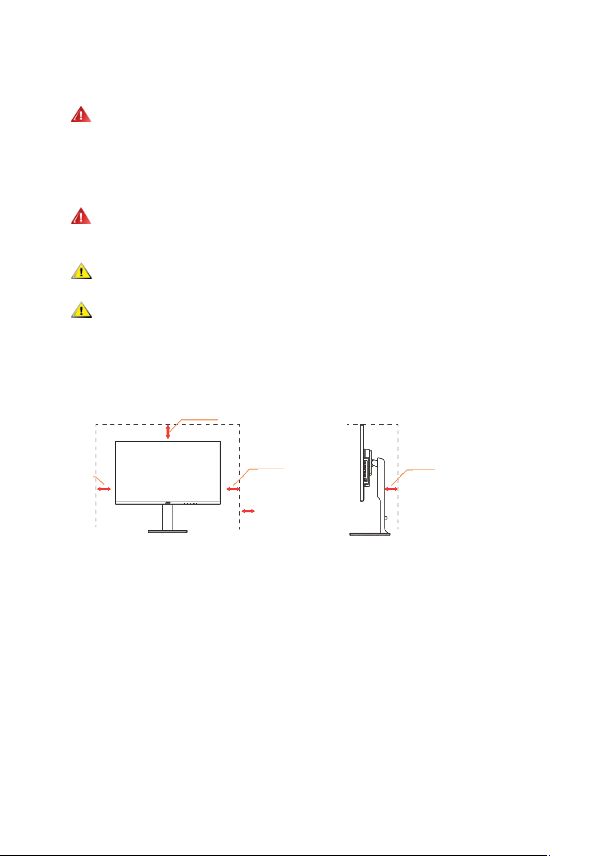
Leave at lease this space
10cm
4 inches
4 inches
4 inches
Installation
Do not place the monitor on an unstable cart, stand, tripod, bracket, or table. If the monitor falls, it can injure a
person and cause serious damage to this product. Use only a cart, stand, tripod, bracket, or table recommended by
the manufacturer or sold with this product. Follow the manufacturer’s instructions when installing the product and
use mounting accessories recommended by the manufacturer. A product and cart combination should be moved
with care.
Never push any object into the slot on the monitor cabinet. It could damage circuit parts causing a fire or
electric shock. Never spill liquids on the monitor.
Do not place the front of the product on the floor.
Leave some space around the monitor as shown below. Otherwise, air-circulation may be inadequate hence
overheating may cause a fire or damage to the monitor.
See below the recommended ventilation areas around the monitor when the monitor is installed with the stand:
Installed with stand
11 7/8 inches
30cm
10cm
10cm
around the set
Page 7
7
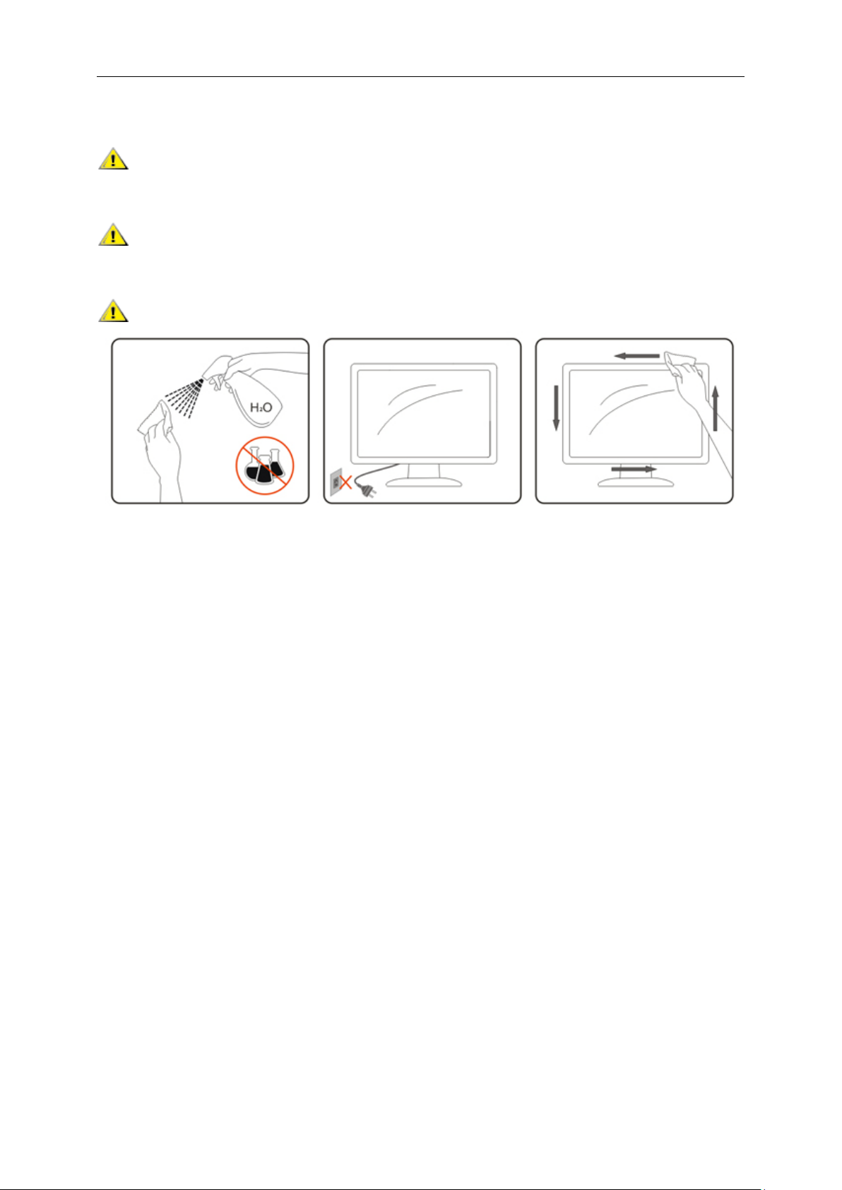
Cleaning
Clean the cabinet regularly with cloth. You can use soft-detergent to wipe out the stain, instead of
strong-detergent which will cauterize the product cabinet.
When cleaning, make sure no detergent is leaked into the product. The cleaning cloth should not be too rough
as it will scratch the screen surface.
Please disconnect the power cord before cleaning the product.
Page 8

8
Other
If the product is emitting a strange smell, sound or smoke, disconnect the power plug IMMEDIATELY and
contact a Service Center.
Make sure that the ventilating openings are not blocked by a table or curtain.
Do not engage the LCD monitor in severe vibration or high impact conditions during operation.
Do not knock or drop the monitor during operation or transportation.
For display with glossy bezel the user should consider the placement of the display as the bezel may cause
disturbing reflections from surrounding light and bright surfaces.
Page 9

9
Setup
CD Manual Base Stand Power Cable
Audio Dual link DVI Analog Cabel DP HDMI USB MHL
Monitor
Contents i n Box
Not all signal cables (CD, Audio, Dual link DVI, Analog, DP, HDMI, MHL and USB cables) will be provided for
all countries and regions. Please check with the local dealer or AOC branch office for confirmation.
Page 10
10
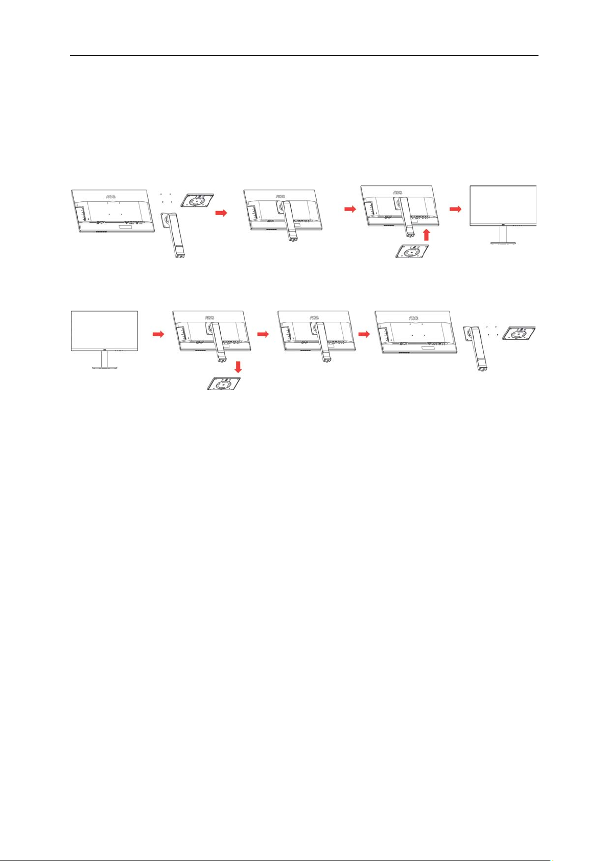
Setup Base
Please setup or remove the base following the steps as below.
Please place the monitor on a soft and flat surface to prevent the scratch.
Setup:
Remove:
Page 11
11
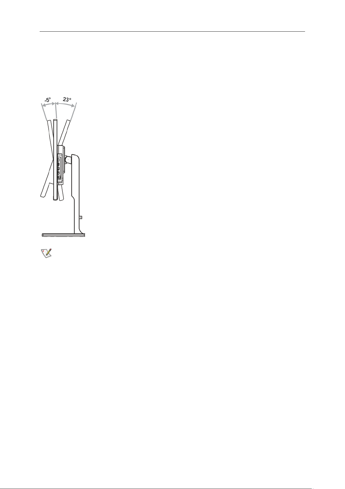
Adjusting Viewing A ngle
For optimal viewing, it is recommended to look at the full face of the monitor, and then adjust the monitor's angle to
your own preference.
Hold the stand so you will not topple the monitor when you change the monitor's angle.
You are able to adjust the monitor's angle from -5° to 23 °.
NOTE:
Do not adjust the viewing angle over 23 degrees in order to avoid damage.
Page 12

12
Q2777PQU
U2777PQU
(1) VGA: 1920 x 1080/60Hz (Maximum)
(1) VGA: 1920 x 1080/60Hz (Maximum)
(2) Dual-Link DVI: 2560 x 1440/60Hz (Maximu m)
(2) Dual-Link DVI: 3840 x 2160/30Hz (Maximu m)
(3) HDMI: 2560 x 1440/60 Hz ( Ma xi mum)
(3) HDMI: 3840 x 2160/60 Hz ( Ma xi mum)
(4) DP: 2560 x 1440/60Hz (Maxim u m)
(4) DP: 3840 x 2160/60Hz (Maxim u m)
Connecting the Monitor
Cable Connections In Back of Monitor and Computer:
1 Power
2 Dual-link DVI
3 HDMI 1.4b (Q2777PQU)/ HDMI 2.0(U2777PQU)/MHL
4 Display port
5 Analog (D-Sub 15-Pin VGA cable)
6 AUDIO IN
7 Earphone out
8 USB 3.0 upstream
9 USB 3.0 downstream
10 USB 3.0+Quick Charging
11 USB 2.0 downstream
12 USB 2.0 downstream
To protect equipment, always turn off the PC and LCD monitor before connecting.
1 Connect the power cable to the AC port on the back of the monitor.
2 Optional – (Requires a video card with DVI port) – Connect one end of the DVI cable to the back of the monitor
and connect the other end to the computer’s DVI port.
3 Optional – (Requires a video card with HDMI/MHL port) – Connect one end of the HDMI/MHL cable to the back
of the monitor and connect the other end to the computer’s HDMI/MHL port.
4 Optional – (Requires a video card with DP port) – Connect one end of the DP cable to the back of the monitor
and connect the other end to the computer’s DP port.
5 Connect one end of the 15-pin D-Sub cable to the back of the monitor and connect the other end to the
computer's D-Sub port
6 Turn on your monitor and computer.
7 Video content supporting resolution:
If your monitor displays an image, installation is complete. If it does not display an image, please refer
Troubleshooting.
Page 13
13
Adjusting
Setting Optimal Resolution
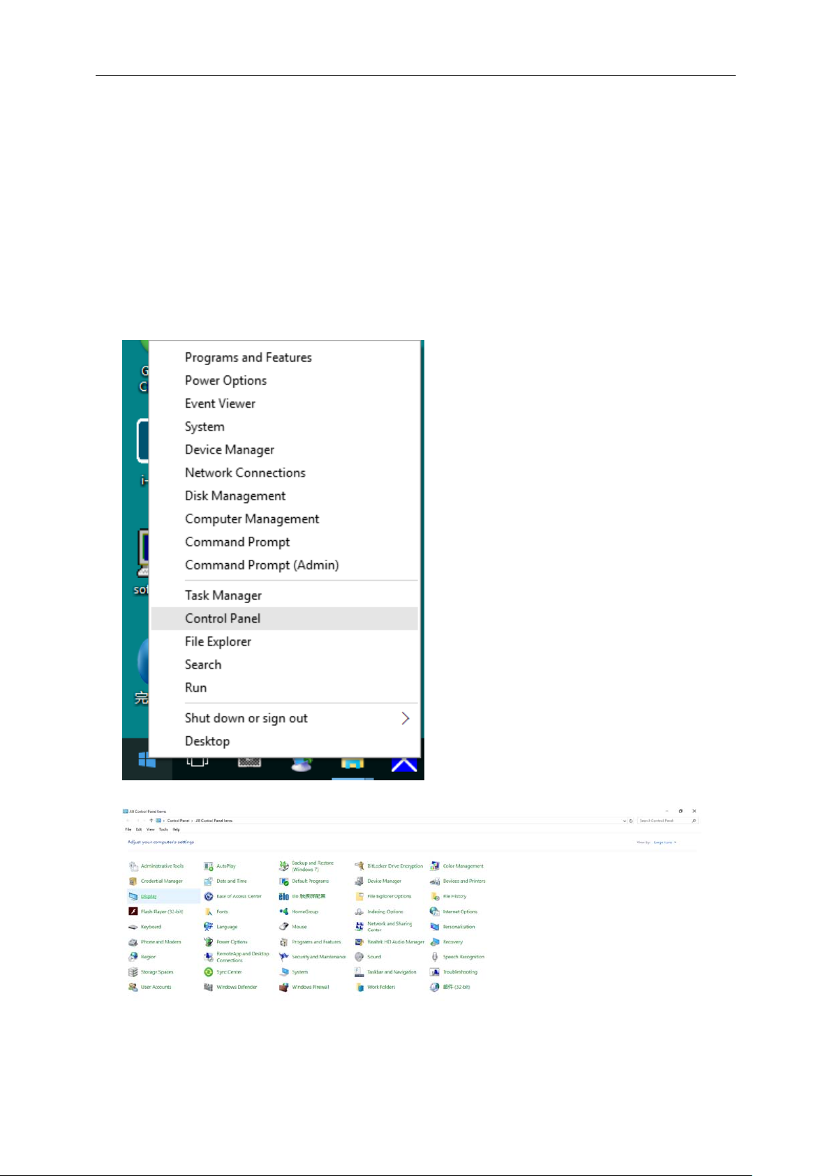
Windows 10
For Windows 1 0:
• Right click START.
• Click "CONTROL PANEL".
• Click "DISPLAY".
Page 14

14
• Click on the "Change display settings" button.
• Set the resolution SLIDE-BAR t o Opt imal preset resolution.
Page 15
15
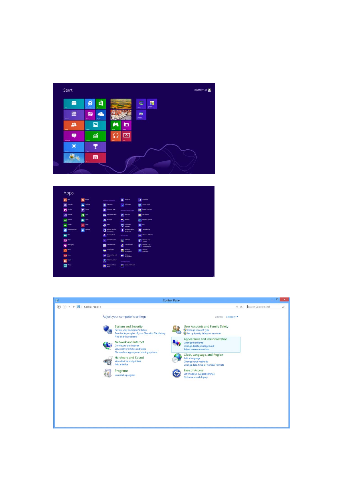
Windows 8
For Windows 8:
• Right click and click All apps at the bottom-right of the screen.
• Set the "View by" to "Category".
• Click "Appearance and Personalization".
Page 16
16
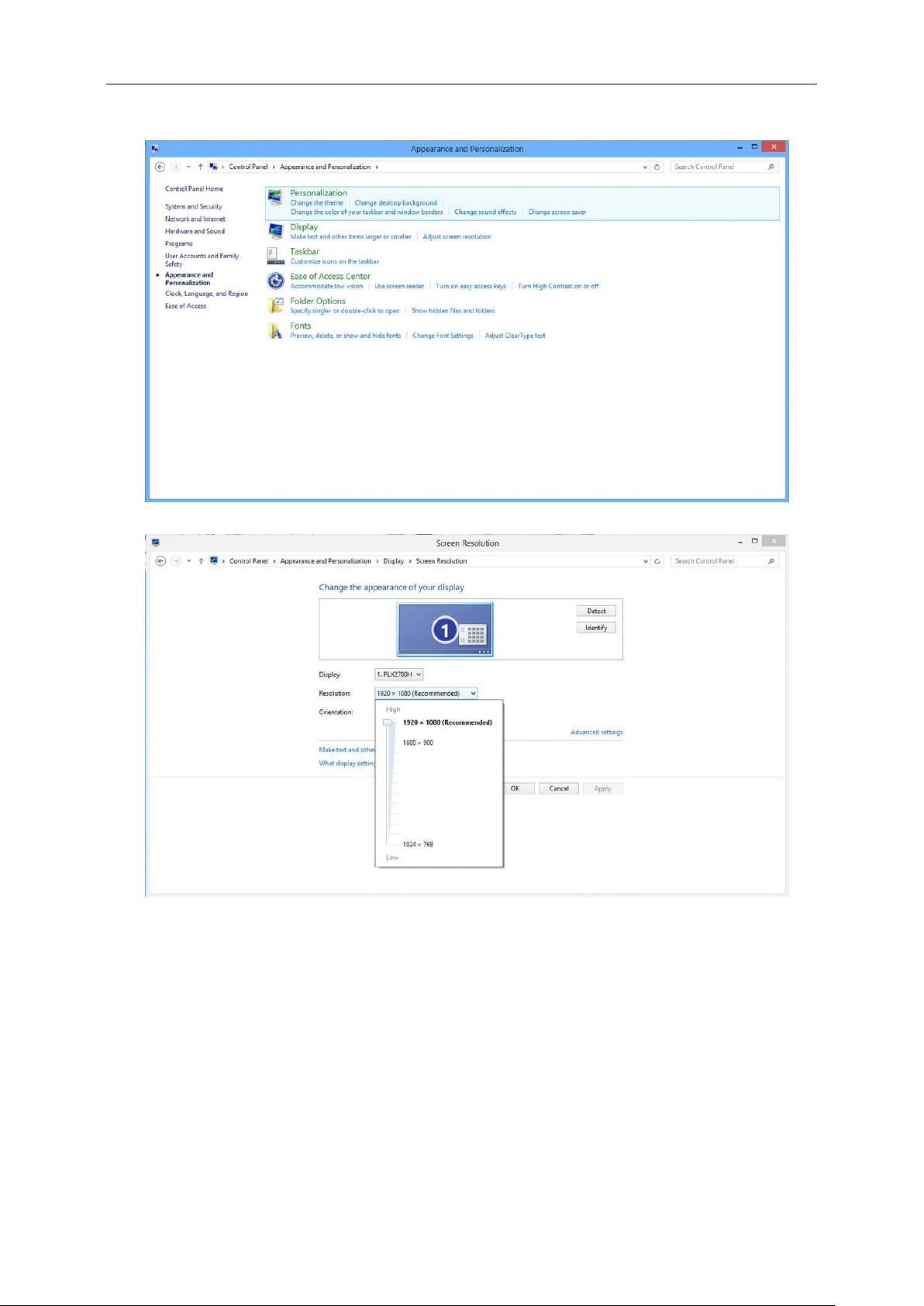
• Click "DISPLAY".
• Set the resolution SLIDE-BAR t o Opt imal preset resolution
Page 17
17
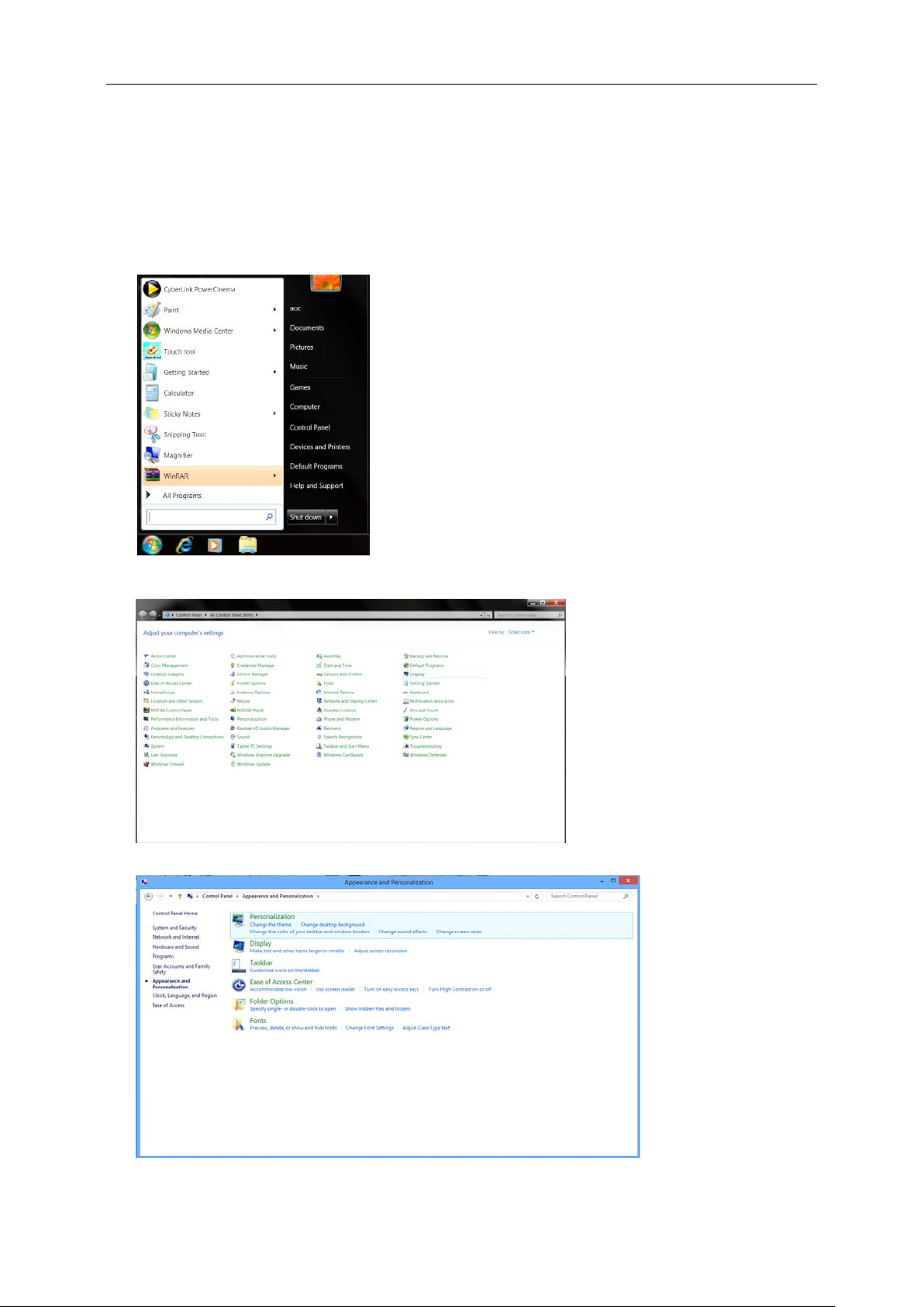
Windows 7
For Windows 7:
• Click START.
• Click "CONTROL PANEL".
• Click "Appearance".
• Click "DISPLAY".
Page 18

18
• Click on the "Change display settin gs " button.
• Set the resolution SLIDE-BAR to Optimal preset resolution
Page 19

19
Hotkeys
1
Source/Auto/Exit
4
Menu/Enter
5
Power
2 Clear Vision/<
3 Volume/>
Menu/Enter
Press to display the OSD or confirm the selection.
Power
Press the Power button to turn on/off the monitor .
Volume/>
When there is no OSD, press Volume adjust volume.
Auto / Exit / Source hot k ey
When there is no OSD, press Auto/Source button continuously about 2 second to do auto configure. When the
OSD is closed, press Source button will be Source hot key function. Press Source button continuously to select the
input source showed in the message bar, press Menu/Enter button to change to the source selected.
Page 20

20
Clear Vision
1. When there is no OSD, Press the “<” button to activate Clear Vision.
2. Use the “<” or “ >” butto ns to select between weak, medium, strong, or off settings. Default setting is always
“off”.
3. Press and hold “<” button for 5 seconds to activate the Clear Vision Demo, and a message of “Clear Vision
Demo: on” will be display on the screen for a duration of 5 seconds. Press Menu or Exit button, the message
will disappear. Press and hold “<” button for 5 seconds again, Clear Vision Demo will be off.
Clear Vision function provides the best image viewing experience by converting low resolution and blurry images
into clear and vivid images.
Since the MHL provides mobile phone charging function and share the same connector with HDMI, Whether the
MHL is set to On, Off or Standby mode, the MHL port provides power to charge the connected device
simultaneously. In Standby and Off energy saving of ErP not applicable for the MHL charging functionality.
Page 21

21
OSD Setting
Basic and s im ple instruction on the control key s .
1. Press the
2. Press
press the MENU-button to activate it. If there is a sub-menu, press
sub-menu functions.
3. Press or to change the settings of the selected function. Press AUTO t o exit. If you want to
adjust any other function, repeat steps 2-3.
4. OSD Lock Function: To lock the OSD, press and hold the
press
while the monitor is off and then press
Notes:
1. If the product has only one signal input, the item of "Input Select" is disabled.
2. If the product screen size is 4:3 or input signal resolution is native resolution, the item of "Image Ratio" is
disabled.
3. One of Clear vision, DCR, Color Boost, and Picture Boost functions is activated; the other three functions are
turned off accordingly.
MENU-button to activate the OSD window.
or to navigate through the functions. Once the desired function is highlighted,
or to navigate through the
MENU-button while the monitor is off and then
power button to turn the monitor on. To un-lock the OSD - press and hold the MENU-button
power button to turn the monitor on.
Page 22

22
Luminance
1 Press
MENU (Menu) to display menu.
2 Press
3 Press
4 Press
5 Press
or to select
or to select submenu.
or to adjust.
(Luminance), and press
MENU to enter.
AUTO to exi t.
Contrast 0-100 Contrast from Digital-register.
Brightness 0-100 Backlight Adjustment
Eco mode
Gamma
DCR
Standard
Text
Internet
Game
Movie
Sports
Gamma1 Adjust to Ga mma 1
Gamma2 Adjust to Gamma 2
Gamma3 Adjust to Gamma 3
Off Disable dynamic contrast ratio
On
Standard Mode
Text Mode
Internet Mode
Game Mode
Movie Mode
Sports Mode
Enable dynamic contrast ratio
Weak
OverDrive
Medium
Strong
Off
Adjust the response time.
Page 23

23
Image Setup
1 Press
MENU (Menu) to display menu.
2 Press
3 Press
4 Press
5 Press
or to select (Image Setup), and press MENU to enter.
or to select submenu.
or to adjust.
AUTO to exit.
Clock 0-100 Adjust picture Clock to reduce Vertical-Line noise.
Phase 0-100 Adjust Picture Phase to reduce Horizontal-Line noise.
Sharpness 0-100 Adjust picture sharpness.
H.Position 0-100 Adjust the horizontal position of the picture.
V.Position 0-100 Adjust the vertical position of the picture.
Page 24

24
Color Setup
1 Press
MENU (Menu) to display menu.
2 Press
3 Press
4 Press
5 Press
or to select (Color Setup), and press MENU to e nter.
or to select submenu.
or to adjust.
AUTO to exit.
Warm Recall Warm Color Temperature from EEPROM.
Normal Recall Normal Color Temperature from EEPROM.
Color Temp.
DCB Mode
DCB Demo ON/OFF Disable or Enable Demo.
Cool Recall Cool Color Temperature from EEPROM.
sRGB Recall SRGB Color Temperature from EEPROM.
User Recall User Color Temperature from EEPROM
Full Enhance ON/OFF Disable or Enable Full Enhance Mode.
Nature Skin ON/OFF Disable or Enable Nature Skin Mode.
Green Field ON/OFF Disable or Enable Green Field Mode.
Sky-blue ON/OFF Disable or Enable Sky-blue Mode.
AutoDetect ON/OFF Disable or Enable AutoDetect Mode.
Red 0-100 Red gain from Digital-register.
Green 0-100 Green gain from Digital-register.
Blue 0-100 Blue gain from Digital-register.
Page 25

25
Picture Boo st
1 Press
MENU (Menu) to display menu.
2 Press
3 Press
4 Press
5 Press
or to select (Picture Boost), and press MENU to enter.
or to select submenu.
or to adjust.
AUTO to exi t.
Bright Frame ON/OFF Enable/Disable Bright Frame
Frame Size 14-100 Adjust the Size of the Frame
Brightness 0-100 Brightness Adjustment for Enhance Area
Contrast 0-100 Contrast Adjustment for Enhance Area
H. position 0-100 Adjust the horizontal position of the Frame
V. position 0-100 Adjust the vertical position of the Frame
Note:
Adjust the brightness, contrast, and position of the Bright Frame for better viewing experience.
Page 26

26
OSD Setup
1 Press
MENU (Menu) to display menu.
2 Press or to select (OSD Setup), and press MENU to enter.
3 Press
4 Press
5 Press
or to select submenu.
or to adjust.
AUTO to exit.
English, France , Spanish,
Portugues,German,
Language
Timeout 5-120 Adjust the OSD timeout.
H. Position 0-100
V. Position 0-100 Adjus t the vertical position of the OSD.
Transparence 0-100 Adjust the OSD
Break
Reminder
DP Capability 1.1/1.2
Italian,Dutch,Swedish, Finnish,
Polish ,Czech, Russia,Korea,
TChina, SChina,Japanese.
ON/OFF
Select the OSD language
Adjust the horizontal position of the
OSD.
Break Reminder if the user continuely
work for more than 1 hours
1. In DP 1.1 mode, DP-out outputs full
image which is from DP-in if DP-in
received image data.
2. In DP 1.2 mode,
(A) DP-out outputs full image which is
from DP-in if DP graphic card outputs
single monitor data.
(B) DP-out outputs next 1 or 2 monitor
image(s) if DP graphic card outputs 2 or
3 monitor images by daisy chain.
(U2777PQU)
HDMI 1.4/2.0
The factory default setting is at HDMI
2.0.But HDMI 1.4 supports most
Blu-Ray/DVD players on the market.
(U2777PQU)
Page 27

27
PIP Setting
1 Press
MENU (Menu) to display menu.
2 Press
3 Press
4 Press
5 Press
or to select PIP, and press MENU to enter.
or to select submenu.
or to adjust.
AUTO to exi t.
PIP OFF / PIP / PBP Disable or Enable PIP or PBP.
Main Source
Sub Source
Size Small / Middle / Large Select screen size.
Position
Audio
Swap
D-SUB/ Dual-link
DVI/HDMI/MHL/DP
D-SUB/ Dual-link
DVI/HDMI/MHL/DP
Right-up
Right-down
Left-up
Left-down
On: PIP Audio
Off: Main Audio
On: Swap
Off: non action
Select main screen source.
Select sub screen source.
Set the screen location.
Disable or Enable Audio Setup.
Swap the screen source.
Page 28

28
Please refer below table for compatibility of main/sub input source.
SUB Source
SUB Source
PIP
D-sub
Dual-link DVI ∨ ∨ ∨ ∨
HDMI/MHL ∨ ∨ ∨ ∨
DP
PBP
D-sub
Dual-link DVI
HDMI/MHL ∨ ∨ ∨ ∨
DP ∨ ∨ ∨ ∨
Main Source
D-sub Dual-link DVI HDMI/MHL DP
∨ ∨ ∨ ∨
∨ ∨ ∨ ∨
Main Source
D-sub Dual-link DVI HDMI/MHL DP
∨ ∨ ∨ ∨
∨ ∨ ∨ ∨
Page 29

29
Extra
1 Press
MENU (Menu) to display menu.
2 Press or to select (Extra), and press MENU to enter.
3 Press
4 Press
5 Press
or to select submenu.
or to adjust.
AUTO to exit.
Auto Auto Detect input signal
D-SUB Select D-SUB signal source as input
Input Select
Auto Config.
Off Timer 0-24 hrs Select DC off time.
Image Ratio
Dual-link DVI Select DVI signal source as input
HDMI/MHL Select HDMI/MHL signal Sourc e as input
DP Select DP signal Source as input
Yes / No Auto adjust.the picture to default.
Wide
4:3
Movie 1
Movie 2
1:1
16:9 or 16:10
4:3 or 5:4
over scan: Top 9% ; Down 9%
over scan: Top 9% ; Down 17%.
Native resolution
DDC/CI Yes / No Turn on or off DDC/CI Support.
Reset Yes / No Reset the menu to default.
Notes:
1. If the DP video content supports DP1.2, please select DP1.2 for D P Capability; otherwise, please select DP1.1.
2. movie1 and movie2 only support digital source.
3. Image Ratio and PIP/PBP can be only one.
4. movie1 and movie2 only support Video Timing(example:480I,480P,576I,576P,720P,1080i,1080P)
Page 30

30
Exit
1 Press
MENU (Menu) to display menu.
2 Press
3 Press
or to select (Exit), and press MENU to enter.
AUTO to exit.
LED Indicator
Status LED Color
Full Power Mode Blue
Power Saving Red
Page 31

31
Driver
Monitor Driver
Windows 10
• Start Windows® 10
• Right click START.
• Click "Control Pa nel".
• Click on the "Display" icon.
Page 32

32
• Click on the "Change display settin gs " button
• Click the "Advanced Settings" button.
Page 33

33
• Clic k the "Monitor" tab and then click the "Properties" button.
• Click th e "Driver" tab.
• Open the "Update Driver Software-Generic PnP Monitor" window by clicking on "Up date Driver... “and then
click the "Browse m y c om put e r for drive r software" button.
Page 34

34
• Select "Let me pick f rom a list of dev ic e drivers on my c om puter".
• Click th e "Have Disk" button. Click on the "Browse" button and navigate to the following directory:
X:\Driver\module name(whe re X is the drive letter designator for the CD-ROM drive).
• Select the "xxx.inf" file and click the "Open" but ton. Clic k the "OK" button.
• Select your monitor model and click the "Next" button. The files will be copied from the CD to your hard disk
drive.
• Close all open windows and remove the CD.
• Restart the system. The system will automatically select the maximum refresh rate and corresponding Color
Matching Profiles.
Page 35

35
Windows 8
• Start Windows® 8
• Right click and click All apps at the bottom-right of the screen.
• Click on the "Control Panel" icon
• Set the "View by" to "Large ic ons " or "Small ico ns ".
• Click on the "Display" icon.
Page 36

36
• Click on the "Change display settin gs " button.
• Click th e "Adva nc e d S e t t ings" button.
Page 37

37
• Click th e "Monitor" tab and then click the "Properties"
• Click th e "Driver" tab.
button.
• Open the "Update Driver S oftw a re-Generic PnP Monitor" w i ndow by clicking on "Update Dr iv e r..." and
then click the "Browse my c om put e r for drive r software" button.
Page 38

38
• Select "Let me pick f rom a list of dev ic e drivers on my c om puter".
• Click th e "Have Disk" button. Click on the "Browse" button and navigate to the following directory:
X:\Driver\module name (where X is the drive letter designator for the CD-ROM drive).
• Select the "xxx.inf" file and click the "Open" button. Click the "OK" button.
• Select your monitor model and click the "Next" button. The files will be copied from the CD to your hard disk
drive.
• Close all open windows and remove the CD.
• Restart the system. The system will automatically select the maximum refresh rate and corresponding Color
Matching Profiles.
Page 39

39
Windows 7
• Start Windows® 7
• Click on the "Start" button and then click on "Control P a ne l".
• Click on the "Display" icon.
• Click on the "Change display settin gs " button.
Page 40

40
• Click the "Advanced Settings" button.
• Clic k the "Monitor" tab and then click the "Properties" button.
• Click th e "Driver" tab.
Page 41

41
• Open the "Update Driver Software-Generic PnP Monitor" window by clicking on “Update Driver... " and
then click the "Browse m y c om put e r for drive r software" button.
• Select "Let me pick f rom a list of dev ic e drivers on my c om puter".
• Click th e "Have Disk" button. Click on the "Browse" button and navigate to the following directory:
X:\Driver\module name(w here X is the drive letter designator for the CD-ROM drive).
Page 42

42
• Select the "xxx.inf" file and click the "Open" button. Click the "OK" button.
• Select your monitor model and click the "Next" button. The files will be copied from the CD to your hard disk
drive.
• Close all open windows and remove the CD.
• Restart the system. The system will automatically select the maximum refresh rate and corresponding Color
Matching Profiles.
Page 43

43
i-Menu
Welcome to “i-Menu” software by AOC. i-Menu makes it easy to adjust your monitor display setting by using on
screen menus instead of the OSD button on the monitor. To complete installation, please follow the installation
guide.
Page 44

44
e-Saver
Wel come to us e AOC e-Saver monitor power management software! The AOC e-Saver features Smart Shutdown
functions for your monitors, allows your monitor to timely shutdown when PC unit is at any status (On, Off, Sleep or
Screen Saver); the actual shutdown time depends on your preferences (see example below).
Please click on "driver/e-Saver/setup.exe" to start installing the e-Saver so ftware, follow the install wizard to
complete software installation.
Under each of the four PC statuses, you may choose the desired time (in minutes) from the pull-down menu for
your monitor to automatically shutdown. The example below illustrated:
1) The monitor will never shutdown when the PC is powered on.
2) The monitor will automatically shutdown 5 minutes after the PC is powered off.
3) The monitor will automatically shutdown 10 minutes after the PC is in sleep/stand-by mode.
4) The monitor will automatically shutdown 20 minutes after the screen saver appears.
You can click “RESET” to set the e-Saver to its default settings like below.
Page 45

45
Screen+
Welcome to "Screen+" software by AOC. Screen+ software is a desktop screen splitting tool; it splits the desktop
into different panels, and each panel displays a different window. You only need to drag the window to a
corresponding panel when you want to access it. It supports multiple monitor display to make your task easier.
Please follow the installation software to install it.
Page 46

46
Troubleshoot
Problem & Que s tion
Power LED Is Not O N
No images on t he s creen
Possible Solutions
Make sure the power button is ON and the Power Cord is properly connected
to a grounded power outlet and to the monitor.
Is the power cord connected properly?
Check the power cord connection and power supply.
Is the cable connected correctly?
(Connected using the D-sub cable)
Check the DB-15 cable connection.
(Connected using the DVI cable)
Check the DVI cable connection.
* DVI inpu t is not available on every model.
If the power is on, reboot the computer to see the initial screen (the login
screen), which can be seen.
If the initial screen (the login screen) appears, boot the computer in the
applicable mode (the safe mode for Windows ME/2000) and then change
the frequency of the video card.
(Refer to the Setting the Optimal Resolution)
If the initial screen (the login screen) does not appear, contact the
Service Center or your dealer.
Can you see "Input Not Supported" on the screen?
You can see this message when the signal from the video card exceeds
the maximum resolution and frequency that the monitor can handle
properly.
Adjust the maximum resolution and frequency that the monitor can
handle properly.
Make sure the AOC Monitor Drivers are installed.
Picture Is Fuzzy & Has
Ghosting Shadowing P roblem
Picture Bounces, Flickers Or
Wave Pattern Appears In The
Picture
Adjust the Contrast and Brightness Controls.
Press to auto adjust.
Make sure you are not using an extension cable or switch box. We
recommend plugging the monitor directly to the video card output connector
on the back.
Move electrical devices that may cause electrical interference as far away
from the monitor as possible.
Use the maximum refresh rate your monitor is capable of at the resolution
you are using.
Page 47

47
Monitor Is Stuc k In Active
Off-Mode"
The Computer Power Switch should be in the ON position.
The Computer Video Card should be snugly fitted in its slot.
Make sure the monitor's video cable is properly connected to the computer.
Inspect the monitor's video cable and make sure no pin is bent.
Make sure your computer is operational by hitting the CAPS LOCK key on
the keyboard while observing the CAPS LOCK LED. The LED should either
turn ON or OFF after hitting the CAPS LOCK key.
Missing one of t he primary
colors ( RE D, GREEN, or
BLUE)
Screen image is not centered
or sized properly
Picture has color defects
(white doe s not look white)
Horizontal or vertica l
disturbances on the screen
Inspect the monitor's video cable and make sure that no pin is damaged.
Make sure the monitor's video cable is properly connected to the computer.
Adjust H-Position and V-Position or press hot-key (AUTO).
Adjust RGB color or select desired color temperature.
Use Windows 95/98/2000/ME shut-dow n mode to adjust CLOCK and
PHASE.
Press to auto -adjust.
Page 48

48
Specification
General Specification(Q2777PQU)
Model name Q2777PQU
Driving system TFT Color L CD
Viewable Image Size 68.47cm diagonal
Panel
Others
Physical
Characteristics
Environmental
Pixel pitch 0.2331(H)mm x 0. 2331(V)mm
Video R, G, B Analog Interface & Digital Interface
Separate Sync. H/V TTL
Display Color 16.7M Colors
Horizontal scan range 30KHz ~99KHz
Horizontal scan
Size(Maximum)
Vertical scan range
Vertical scan Size(Maximum) 335.66 mm
Optimal preset resolution
Plug & Play VESA DDC2B/CI
Speaker 3 W x 2
Power Source 100-240V AC, 50/60Hz,1.5A
Power Consumption
Off timer 0-24 hrs
Connector Type
Signal Cable Type Detachable
Dimensions & Weight:
Height (with base) 531.1~ 401.2mm
Width 614.9 mm
Depth 194.3 mm
Weight (monitor only) 7.3 kg
Temperature:
Operating 0° to 40°C
Non-Operating -25° to 55°C
Humidity:
Operating 10% to 85% (non-condensing)
Non-Operating 5% to 93% (non-condensing)
Altitude:
Operating 0~ 5000m(0~ 16404 ft)
Non-Operating 0~ 12192m (0~ 40000 ft )
596.74 mm
23Hz~76Hz ( MHL)
50Hz ~ 76Hz (D-SUB/ Dual-link DVI/HDMI 1.4b /DP)
1920x1080@60Hz (D-SUB\MHL)
2560x1440@60Hz (Dual-link DVI\HDMI 1.4b \DP)
Typical (Brightness = 90,Contrast = 50) 38W
Max (Brightness = 100,Contrast = 100) ≤73W
Power saving ≤1W
VGA\ Dual-link DVI \HDMI\MHL\DP\ Line in\Earphone out\
USB2.0 x 2/USB3.0 x 2
Page 49

49
General Specification(U2777PQU)
Model name U2777PQU
Driving system TFT Color L CD
Viewable Image Size 68.47cm diagonal
Panel
Others
Physical
Characteristics
Environmental
Pixel pitch 0.1554(H)mm x 0. 1554(V)mm
Video R, G, B Analog Interface & Digital Interface
Separate Sync. H/V TTL
Display Color 1.07B Colors
Horizontal scan range
Horizontal s c an
Size(Maximum)
Vertical scan range 23Hz ~ 80Hz
Vertical scan Size(Maximum) 335.66 mm
Optimal preset resolution
Plug & Play VESA DDC2B/CI
Speaker 3W x 2
Power Source 100-240V AC, 50/60Hz,1.5A
Power Consumption
Off timer 0-24 hrs
Connector Type
Signal Cable Type Detachable
Dimensions & Weight:
Height (with base) 531.1~ 401.2mm
Width 614.9 mm
Depth 194.3 mm
Weight (monitor only) 7.3 kg
Temperature:
Operating 0° to 40°C
Non-Operating -25° to 55°C
Humidity:
Operating 10% to 85% (non-condensing)
Non-Operating 5% to 93% (non-condensing)
Altitude:
Operating 0~ 5000m(0~ 16404 ft)
Non-Operating 0~ 12192m (0~ 40000 ft )
30KHz ~99KHz (D-SUB/ Dual-link DVI/HDMI1.4b/MHL)
30KHz -160KHz (HDMI2.0 /DP)
596.74 mm
1920x1080@60Hz (D-SUB/MHL)
3840x2160@30Hz (Dual-link DVI\HDMI1.4b)
3840x2160@60Hz (HDMI2.0\DP)
Typical (Brightness = 90,Contrast = 50) 47W
Max (Brightness = 100,Contrast = 100) ≤82W
Power saving ≤1W
VGA\ DVI Dual link \HDMI\MHL\DP\ Line in\Earphone out\
USB2.0 x 2/USB3.0 x 2
Page 50

50
Standard
Resolution
H. Frequenc y ( kHz)
V. Freque nc y ( Hz)
75
75
60
60
Preset Display Modes(Q2777PQU)
VGA
VGA
VGA
VGA
SVGA
SVGA
SVGA
SVGA
XGA
XGA
XGA
SXGA
SXGA
WXGA+
WSXGA
FHD
HD
QHD For Dual-link DVI、HDMI、DP 2560x1440@60Hz
IBM MODE DOS
IBM MODE DOS 720x400@70 Hz 31.469
MAC MODE VGA
MAC MODE SVGA 832x624@75Hz 49.725 74.551
MAC MODE XGA 1024x768@75Hz 60.241 74.927
1280×720@60Hz 44.772 59.855
640x480@60Hz
640x480@67Hz 35.000 66.667
640x480@72Hz
640x480@75Hz
800x600@56Hz
800x600@60Hz
800x600@72Hz
800x600@75Hz
1024x768@60Hz
1024x768@70Hz
1024x768@75Hz
1280x1024@60Hz
1280x1024@75Hz
1440x900@60Hz
1680x1050@60Hz
1920x1080@60Hz
1280x960@60 Hz
640x350@70 Hz
640x480@67Hz
31.469
37.861
37.5
35.156
37.879
48.077
46.875
48.363
56.476
60.023
63.981
79.976
55.935
65.290
67.5
60
88.787
31.469
35.000
59.94
72.809
56.25
60.317
72.188
60.004
70.069
75.029
60.02
75.025
59.887
59.954
59.951
70.087
70.087
66.667
Page 51

51
Standard
Resolution
H. Frequenc y ( kHz)
V. Freque nc y ( Hz)
75
75
60
60
Preset Display Modes(U2777PQU)
VGA
VGA
VGA
VGA
DOS MODE 720x400@70Hz 31.469 70.087
SVGA
SVGA
SVGA
SVGA
MAC MODE 832x624@75Hz 49.725 74.551
XGA
XGA
XGA
SXGA
SXGA
WXGA+
WSXGA
FHD
HD
HD 1280x720@60 Hz
QHD 2560x1440@60Hz 88.786 59.9
UHD 3840X2160@30Hz 67.5 30
UHD 3840X2160@60Hz 133.32 60
640x480@60Hz
640x480@67Hz
640x480@72Hz
640x480@75Hz
800x600@56Hz
800x600@60Hz
800x600@72Hz
800x600@75Hz
1024x768@60Hz
1024x768@70Hz
1024x768@75Hz
1280x1024@60Hz
1280x1024@75Hz
1440x900@60Hz
1680x1050@60Hz
1920x1080@60Hz
1280x960@60 Hz
31.469
35 66.667
37.861
37.5
35.156
37.879
48.077
46.875
48.363
56.476
60.023
63.981
79.976
55.935
64.674
67.5
60
44.772
59.94
72.809
56.25
60.317
72.188
60.004
70.069
75.029
60.02
75.025
59.887
59.954
59.885
Page 52

52
Pin Assignme nt s
15-Pin Color Dis play Signal Cable
Pin No. Signal Name Pin No. Signal Nam e
1 Video-Red 9 +5V
2 Video-Green 10 Ground
3 Video-Blue 11 N.C.
4 N.C. 12 DDC-Serial data
5 Detect Cable 13 H-sync
6 GND-R 14 V-sync
7 GND-G 15 DDC-S erial c loc k
8 GND-B
24-Pin Color Dis play Signal Cable
Pin No. S ignal Name Pin No. Signa l Na m e
1 T MDS d a ta 2 - 13 TMDS data 3+
2
3 TMDS data 2/4 Shield 15 Ground (for+5V)
4
5 T MDS d a ta 4 + 17 TMDS data 0-
6 DDC Clock 18 TMDS data 0+
7 DDC D a ta 19 TMDS data 0/5 Shield
8 N.C. 20
9 T MDS d a ta 1 - 21 TMDS data 5+
10 TMDS data 1+ 22 TMDS Clock Shield
11 TMDS data 1/3 Shield 23 TMDS Cloc k +
12 T MDS d a ta 3 - 24 TMDS Clock -
TMDS data 2 +
TMDS data 4 -
14
16 Hot Plug Detect
+5V Power
TMDS data 5 -
Page 53

53
GND
AUX_CH(p)
ML_Lane 1 (n)
AUX_CH(n)
19-Pin Color Dis play Signal Cable
Pin No. Signal Name Pin No. Signal Nam e
1 T MDS Da ta 2 + 11 TMDS Clock Shield
2
3 T MDS Da ta 2 13 CEC
4 T MDS Da ta 1 + 14 Reserved (N.C. on device
5 TMDS Data 1Shield 15 SCL
6
7 T MDS Da ta 0 + 17 DDC/CEC Grou n d
8 TMDS Data 0 Shield 18 +5V Pow er
9 T MDS Da ta 0 19 Hot Plug Detect
10
20-Pin Color Dis play Signal Cable
TMDS Data 2 Shield
TMDS Data 1
TMDS Cloc k +
12
16
TMDS Cloc k
SDA
Pin No. Signal Name Pin No. Signal Nam e
1
2
3
4
5
6
7
8
9
10
ML_Lane 3 (n)
GND
ML_Lane 3 (p)
ML_Lane 2 (n)
ML_Lane 2 (p)
GND
ML_Lane 1 (p)
ML_Lane 0 (n)
11
12
13
14
15
16
17
18
19
20
GND
ML_Lane 0 (p)
CONFIG1
CONFIG2
GND
Hot Plug Detect
Return DP_PWR
DP_PWR
Page 54

54
Plug and Play
Plug & Play DDC2B Feature
This monitor is equipped with VESA DDC2B capabilities according to the VESA DDC STANDARD. It allows the
monitor to inform the host system of its identity and, depending on the level of DDC used, communicate additional
information about its display capabilities.
The DDC2B is a bi-directional data channel based on the I2C protocol. The host can request EDI D information over
the DDC2B channel.
Page 55

55
Regulation
FCC Notice
FCC Class B Radio Frequency Interfe rence Statement WARNING: (FOR FCC CERTIFIED MODELS)
NOTE: This equipment has been tested and found to comply with the limits for a Class B digital device, pursuant to
Part 15 of the FCC Rules. These limits are designed to provide reasonable protection against harmful interference
in a residential installation. This equipment generates, uses and can radiate radio frequency energy, and if not
installed and used in accordance with the instructions, may cause harmful interference to radio communications.
However, there is no guarantee that interference will not occur in a particular installation. If this equipment does
cause harmful interference to radio or television reception, which can be determined by turning the equipment off
and on, the user is encouraged to try to correct the interference by one or more of the following measures:
Reorient or relocate the receiving antenna.
Increase the separation between the equipment and receiver.
Connect the equipment into an outlet on a circuit different from that to which the receiver is connected.
Consult the dealer or an experienced radio/TV technician for help.
NOTICE:
The changes or modifications not expressly approved by the party responsible for compliance could void the user's
authority to operate the equipment.
Shielded interface cables and AC power cord, if any, must be used in order to comply with the emission limits.
The manufacturer is not responsible for any radio or TV interference caused by unauthorized modification to this
equipment. It is the responsibilities of the user to correct such interference. It is the responsibility of the user to
correct such interference.
Page 56

56
WEEE Declaration
Disposal of Waste Equipment by Users in Private Household in the European Union.
This symbol on the product or on its packaging indicates that this product must not be disposed of with your other
household waste. Instead, it is your responsibility to dispose of your waste equipment by handing it over to a
designated collection point for the recycling of waste electrical and electronic equipment. The separate collection
and recycling of your waste equipment at the time of disposal will help to conserve natural resources and ensure
that it is recycled in a manner that protects human health and the environment. For more information about where
you can drop off your waste equipment for recycling, please contact your local city office, your household waste
disposal service or the shop where you purchased the product.
WEEE Declaration for India
This symb ol on the product or on its packaging indicates that this product must not be disposed of with your other
household waste. Instead it is your responsibility to dispose of your waste equipment by handing it over to a
designated collection point for the recycling of waste electrical and electronic equipment. The separate collection
and recycling of your waste equipment at the time of disposal will help to conserve natural resources and ensure
that it is recycled in a manner that protects human health and the environment.
For more information about where you can drop off your waste equipment for recycling in India, please visit the
below web link.
www.aocindia.com/ewaste.php.
RoHS Declaration for India
his product complies with all implemented RoHS type regulations worldwide, including but not limited t o, EU,
Korea, Japan, US States (e.g. California), Ukraine, Serbia, Turkey, Vietnam and India.
We continue to monitor, influence and develop our processes to comply with upcoming proposed RoHS type
regulations, including but not limited to, Brazil, Argentina, Canada.
Restriction on Hazardous S ubstances statement (Indi a)
This product complies with the “India E-waste Rule” and prohibits use of lead, mercury, hexaval ent chromium,
polybrominated biphenyls or polybrominated diphenyl ethers in concentrations exceeding 0.1 weight % and 0.01
weight % for cadmium, except for the exemptions set in Schedule 2 of the Rule.
 Loading...