Anvil 261, 261 User Manual

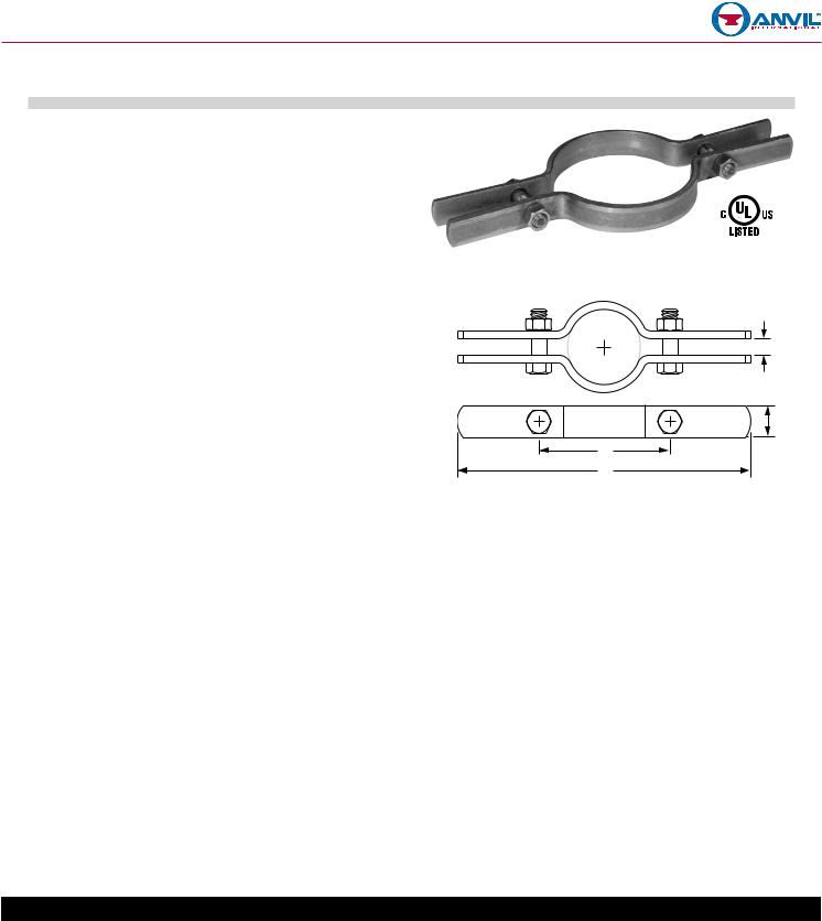
RISER CLAMPS
Fig. 261 (Formerly Afcon Fig. 400)
Size Range: 3⁄4" through 24" Material: Carbon steel
Finish: θ Plain, θ Hot-Dip Galvanized with Zinc Plated Bolts & Nuts, θ Epoxy Coated or θ Painted.
Service: For support of stationary steel pipe risers, cast iron pipe or conduit. This product is not intended for use with hanger rods. For this application refer to Fig. 40 Riser Clamp, page 49.
Maximum Temperature: Plain 650° F, Galvanized and Epoxy 450° F Approvals: Complies with Federal Specification A-A-1192A (Type 8) WW-H-171-E (Type 8), ANSI/MSS SP-69 and MSS SP-58 (Type 8).
UL, ULC Listed (Sizes 1 1⁄2" - 8"). Installation: Clamp is fitted and bolted preferably below a coupling,
hub or welded lugs on steel pipe. Bolt torques should be per industry standards (see page 248). Clamp is designed for standard steel pipe O.D. and this must be considered in sizing the riser for other types of piping.
Ordering: Specify pipe size, figure number, name and finish.
B
L
|
|
FIG. 261: DIMENSIONS (IN) • LOADS (LBS) • TORQUE (FT-LBS) • WEIGHT (LBS) |
|
|
|||||||
|
|
|
|
|
|
|
|
|
|
|
|
|
Pipe |
Max |
Weight |
L |
G |
B |
|
C |
Bolt |
Torque |
|
|
Size |
Load |
Width |
|
Diameter |
Values |
|
||||
|
|
|
|
|
|
|
|||||
|
|
|
|
|
|
|
|
|
|
|
|
|
3⁄4 |
220 |
1.1 |
87⁄8 |
|
27⁄8 |
|
|
|
|
|
|
1 |
1.1 |
|
31⁄8 |
|
3⁄8 |
3⁄8 |
21 |
|
||
|
|
|
|
|
|
||||||
|
11⁄4 |
250 |
1.6 |
10 |
|
31⁄2 |
|
|
|||
|
|
|
|
|
|
|
|||||
|
11⁄2 |
1.6 |
101⁄4 |
|
37⁄8 |
|
|
|
|
|
|
|
|
|
|
|
|
|
|
||||
|
2 |
300 |
1.7 |
1 |
41⁄4 |
|
|
|
|
|
|
|
|
|
|
|
|
|
|||||
|
21⁄2 |
400 |
1.9 |
111⁄4 |
|
43⁄4 |
|
1⁄2 |
7⁄16 |
32 |
|
|
3 |
500 |
1.9 |
113⁄8 |
|
51⁄2 |
|
|
|
|
|
|
31⁄2 |
600 |
2.3 |
127⁄8 |
|
61⁄2 |
|
|
|
|
|
|
4 |
750 |
2.4 |
|
7 |
|
1⁄2 |
1⁄2 |
46 |
|
|
|
|
|
|
|
|||||||
|
5 |
1,500 |
3.6 |
133⁄4 |
|
8 |
|
|
|||
|
|
|
|
|
|
|
|||||
|
6 |
1,600 |
4.0 |
143⁄4 |
11⁄2 |
9 |
|
|
|
|
|
|
8 |
2,500 |
7.6 |
181⁄2 |
|
12 |
|
|
|
|
|
|
10 |
11.1 |
201⁄4 |
|
133⁄4 |
|
5⁄8 |
5⁄8 |
100 |
|
|
|
|
|
|
|
|||||||
|
12 |
2,700 |
16.5 |
223⁄4 |
2 |
153⁄4 |
|
|
|||
|
|
|
|
|
|
||||||
|
14 |
17.7 |
24 |
|
171⁄4 |
|
|
|
|
|
|
|
|
|
|
|
|
|
|
||||
|
16 |
|
30.4 |
26 |
|
193⁄4 |
|
|
|
|
|
|
18 |
2,900 |
33.8 |
28 |
21⁄2 |
213⁄4 |
|
3⁄4 |
3⁄4 |
150 |
|
|
20 |
|
35.0 |
30 |
|
233⁄4 |
|
|
|
|
|
|
24 |
3,200 |
82.0 |
363⁄4 |
3 |
30 |
|
1 |
7⁄8 |
190 |
|
|
|
|
|
|
|
|
|
|
|
|
|
|
|
|
PROJECT INFORMATION |
|
|
|
|
APPROVAL STAMP |
|||
|
|
|
|
|
|
|
|
|
|
|
|
Project: |
|
|
|
|
|
|
θ Approved |
|
|
|
|
Address: |
|
|
|
|
|
|
θ Approved as noted |
|
|
||
Contractor: |
|
|
|
|
|
|
θ Not approved |
|
|
||
Engineer: |
|
|
|
|
|
|
Remarks: |
|
|
|
|
|
|
|
|
|
|
|
|
|
|
|
|
Submittal Date: |
|
|
|
|
|
|
|
|
|
|
|
|
|
|
|
|
|
|
|
|
|
|
|
Notes 1: |
|
|
|
|
|
|
|
|
|
|
|
|
|
|
|
|
|
|
|
|
|
|
|
Notes 2: |
|
|
|
|
|
|
|
|
|
|
|
|
|
|
|
|
|
|
|
|
|
|
|
PH-1.18
 Loading...