Anvil 160, 163, 165A, 161, 164 User Manual
...
pipe shields & Saddles
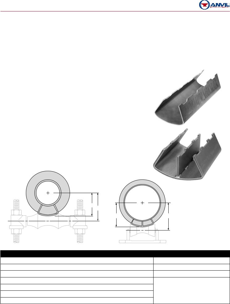
Pipe Covering Protection Saddle
For Nominal Thickness of Covering Shown
Fig. 160: |
1" |
Fig. 161: 11⁄2" |
Fig. 162: 2" |
Fig. 163: |
21⁄2" |
Fig. 164: 3" |
Fig. 165: 4" |
Fig. 165A: 4" (Alloy) |
Fig. 166A: 51⁄2" (Alloy) |
||
|
|
|
|
Size Range: 3⁄4" through 36"
Material:
•Figs. 160, 161, 162, 163, 164, and 165 are curved carbon steel plate.
•Figs. 165A and 166A are alloy steel manufactured from ASTM A 387 Grade 22 Chrome Molybdenum steel plate.
•Figs. 165A and 166A have a welded-in center plate in all sizes.
•All other saddles have a welded-in center plate for pipe sizes 12" and larger.
•All saddles are 12" long with side edges turned up.
Finish: Plain
Service: Designed for use on insulated high temperature systems where heat losses are to be kept to a minimum and to protect insulation against damage.
Maximum Temperature: 650° F carbon steel, 950° F alloy steel.
Approvals: Complies with Federal Specification A-A-1192A (Type 39A & 39B), WW-H-171-E (Type 40A & 40B), ANSI/MSS SP-69 and MSS SP-58 (Type 39A & 39B).
Features: Permits finished, weather tight covering at all points of pipe support.
Ordering: Specify pipe size, figure number and name. Data for 42" size available on request. Installation: It is recommended that saddle be welded to the pipe.
C
L
C
L
C
D
C E
|
Continued on Following Page. |
Project information |
Approval Stamp |
Project: |
Approved |
Address: |
Approved as noted |
Contractor: |
Not approved |
Engineer: |
Remarks: |
Submittal Date: |
|
Notes 1: |
|
Notes 2: |
|
Catalog PH-2008

pipe shields & Saddles
Fig. 160 to Fig 166A |
Pipe Covering Protection Saddle (cont.) |
||||||||||||
|
|
|
|
|
|
|
|
|
|
|
|||
|
|
|
|
|
|
|
|
|
|
|
|||
Fig. 160, 161, 162, 163, 164, 165, 165A, 166A: Loads (lbs) • Weight (lbs) • Dimensions (in) |
|||||||||||||
|
|
|
|
|
|
|
|
|
|
|
|
|
|
|
|
|
|
|
Size of Pipe Roll |
Center Line |
Center Line of Pipe to |
||||||
|
|
|
|
|
Center Line of Roll |
||||||||
Pipe |
Fig. |
Max |
|
|
|
|
|
|
of Pipe to |
||||
Weight |
|
|
|
|
|
|
|
|
|
||||
Size |
No. |
Load n |
Figs. 171, |
|
Figs. |
|
Figs. 271, |
Outside of |
|
D |
E |
||
|
|
|
|
||||||||||
|
|
|
|
175, 177 |
|
174, 181 |
|
274, 277 |
Saddle C |
Figs. 171, |
|
Figs. |
Figs. 271, |
|
|
|
|
|
|
|
|
|
|
175, 177 |
|
174, 181 |
274, 277 |
|
160• |
|
1.4 |
2 |
|
21⁄2 |
|
|
15⁄8 |
21⁄16 |
|
21⁄8 |
21⁄4 |
3⁄4 |
161• |
1,200 |
2.1 |
3 |
|
31⁄2 |
|
2-31⁄2 |
23⁄16 |
23⁄4 |
|
23⁄4 |
27⁄8 |
|
162• |
|
2.8 |
4 |
|
5 |
|
|
211⁄16 |
35⁄16 |
|
35⁄16 |
33⁄8 |
|
160• |
|
1.4 |
21⁄2 |
|
3 |
|
|
113⁄16 |
25⁄16 |
|
21⁄4 |
27⁄16 |
1 |
161• |
1,200 |
2.1 |
3 |
|
4 |
|
2-31⁄2 |
25⁄16 |
27⁄8 |
|
27⁄8 |
3 |
|
162• |
|
2.8 |
4 |
|
5 |
|
|
27⁄8 |
31⁄2 |
|
31⁄2 |
31⁄2 |
|
160 |
|
1.4 |
21⁄2 |
|
3 |
|
|
115⁄16 |
21⁄2 |
|
27⁄16 |
29⁄16 |
11⁄4 |
161• |
1,200 |
2.1 |
31⁄2 |
|
5 |
|
2-31⁄2 |
29⁄16 |
31⁄16 |
|
31⁄16 |
33⁄16 |
162• |
2.8 |
4 |
|
|
|
3 |
35⁄8 |
|
35⁄8 |
311⁄16 |
|||
|
|
|
|
|
|
|
|||||||
|
163• |
|
3.6 |
5 |
|
6 |
|
4-6 |
33⁄4 |
43⁄8 |
|
43⁄8 |
43⁄8 |
|
160 |
|
1.5 |
3 |
|
31⁄2 |
|
2-31⁄2 |
21⁄8 |
25⁄8 |
|
25⁄8 |
211⁄16 |
11⁄2 |
161• |
1,200 |
2.1 |
31⁄2 |
|
5 |
|
25⁄8 |
31⁄4 |
|
31⁄4 |
35⁄16 |
|
|
|
|
|
||||||||||
162• |
3.2 |
5 |
|
6 |
|
4-6 |
35⁄16 |
4 |
|
4 |
37⁄8 |
||
|
|
|
|
|
|||||||||
|
163• |
|
3.6 |
6 |
|
8 |
|
37⁄8 |
41⁄2 |
|
45⁄8 |
41⁄2 |
|
|
|
|
|
|
|
||||||||
|
160 |
|
1.7 |
31⁄2 |
|
4 |
|
2-31⁄2 |
23⁄8 |
3 |
|
215⁄16 |
31⁄16 |
|
161• |
|
2.3 |
4 |
|
5 |
|
27⁄8 |
31⁄2 |
|
31⁄2 |
39⁄16 |
|
|
|
|
|
|
|
||||||||
2 |
162• |
1,200 |
3.2 |
5 |
|
6 |
|
|
39⁄16 |
41⁄4 |
|
41⁄4 |
43⁄16 |
|
163• |
|
3.6 |
6 |
|
8 |
|
4-6 |
41⁄16 |
43⁄4 |
|
413⁄16 |
43⁄4 |
|
164• |
|
4.5 |
8 |
|
|
|
49⁄16 |
53⁄8 |
|
53⁄8 |
51⁄4 |
|
|
|
|
|
|
|
|
|||||||
|
160 |
|
1.7 |
31⁄2 |
|
5 |
|
2-31⁄2 |
211⁄16 |
31⁄4 |
|
31⁄4 |
35⁄16 |
|
161 |
|
2.8 |
5 |
|
6 |
|
|
35⁄16 |
4 |
|
4 |
315⁄16 |
21⁄2 |
162 |
1,200 |
3.2 |
6 |
|
8 |
|
4-6 |
37⁄8 |
41⁄2 |
|
45⁄8 |
41⁄2 |
|
163 |
|
4.1 |
8 |
|
|
41⁄4 |
51⁄8 |
|
51⁄8 |
5 |
||
|
|
|
|
|
|
|
|||||||
|
164 |
|
4.5 |
|
10 |
|
|
47⁄8 |
55⁄8 |
|
53⁄4 |
51⁄2 |
|
|
|
|
|
|
|
|
|||||||
|
160 |
|
1.9 |
4 |
|
5 |
|
2-31⁄2 |
215⁄16 |
31⁄2 |
|
31⁄2 |
39⁄16 |
|
161 |
|
2.8 |
5 |
|
6 |
|
|
35⁄8 |
45⁄16 |
|
45⁄16 |
41⁄4 |
3 |
162 |
1,200 |
3.6 |
6 |
|
8 |
|
4-6 |
41⁄8 |
413⁄16 |
|
413⁄16 |
411⁄16 |
|
163 |
|
4.1 |
8 |
|
|
|
411⁄16 |
57⁄16 |
|
57⁄16 |
55⁄16 |
|
|
|
|
|
|
|
|
|||||||
|
164 |
|
4.9 |
|
10 |
|
8-10 |
51⁄16 |
6 |
|
6 |
61⁄16 |
|
|
|
|
|
|
|
||||||||
nMaximum recommended loads are applicable only when saddle is used on a flat bearing surface or roller hangers and tack welded to pipe. When saddle is used with a pipe roll, the maximum load for the assembly is the smaller of the two loads.
• Saddles may require notching when used with a U-bolt.
|
Continued on Following Page. |
|
|
Project information |
Approval Stamp |
|
|
Project: |
Approved |
Address: |
Approved as noted |
Contractor: |
Not approved |
Engineer: |
Remarks: |
|
|
Submittal Date: |
|
|
|
Notes 1: |
|
|
|
Notes 2: |
|
|
|
Catalog PH-2008
 Loading...