

Page 1

SAUSAGE CORRAL
Models SC-20, SC-25, SC-40
Series 9300200
Owner’s Manual
Page 2

SAUSAGE CORRAL
P/N 1010598
Rev B
7/99
TABLE OF CONTENTS
Owner Information 1 Installation 6
General 1 Unpacking 6
Warranty Information 1 Equipment Setup 6
Service/Technical Assistance 2 Operation 8
Important Safety Information 2 General 8
Specifications 4 Operating Instructions 8
Electrical Ratings 4 Maintenance 8
Electrical Cord & Plug Configurations 4 Cleaning 8
Capacities 4 Inspecting and Aligning Drive Parts 9
Dimensions 5 Troubleshooting 10
Shipping Weight 5 Wiring Diagrams 11
Replacement Parts 12- 19
Warranty Back Cover
OWNER INFORMATION
General
The Roundup Sausage Corral is a unique and innova tive
way to prepare sausages The sausages are placed in a
"corral" that moves up-and-down over a heated flat grill
surface The corral motion allows the sausages to turn As
the sausages turn, they roll in their own juices, producing
a self-basting sausages that sears in all the natural flavor
The SC-20/25 Model has a split grill and a grease tray
which collects cooking juices for easy disposal The SC40 Model has a larger capacity for higher volume
applications Domestic models are available with either
250°F or 400°F thermostats International models are
available with 200°C thermostats only
This manual provides the safety, installation and operating procedures for the Sausage Corral We recommend
that all information contained in this manual be read prior
to installing and operating the unit
Your Sausage Corral is manufactured from the finest
materials available and is assembled to Roundup's strict
quality standards This unit has been tested at the factory
to ensure dependable trouble-free operation
Warranty Information
Please read the full text of the Limited Warranty in this
manual
If the unit arrives damaged, contact the carrier immediately and file a damage claim with them Save all
packing materials when filing a claim Freight damage
claims are the responsibility of the purchaser and are
not covered under warranty
The warranty does not extend to:
• Damages caused in shipment or damage as result
of improper use
• Installation of electrical service
• Normal maintenance as outlined in this manual
• Malfunction resulting from improper maintenance
• Damage caused by abuse or careless handling
• Damage from moisture into electrical
components
• Damage from tampering with, removal of, or
changing any preset control or safety device
IMPORTANT! Keep these instructions for future reference
If the unit changes ownership, be sure this manual accompanies the equipment
1
Page 3
SAUSAGE CORRAL
OWNER INFORMATION (continued)
Service/Technical Assistance
If you experience any problems with the installation or
operation of your unit, contact your local Roundup
Authorized Service Agency.
Fill in the information below and have it handy when
calling your authorized service agency for assistance.
The serial number is on the specification plate located on
the unit.
Purchased From: ______________________________
Date of Purchase: ______________________________
Model No.: ____________________________________
Refer to the service agency directory included with your
unit.
Authorized Service Agency
Name: _____________________________________ __
Phone No.: ___________________________________
Address: ____________________________________
Use only genuine Roundup replacement parts in this
unit. Use of replacement parts other than those supplied
by the manufacturer will void the warranty. Your
Authorized Service Agency has been factory trained and
has a complete supply of parts for this unit.
Serial No.: ____________________________________
Mfg. No.: ____________________________________
You may also contact the factory at 1-800-253-2991 if
you have trouble locating your local authorized service
agency.
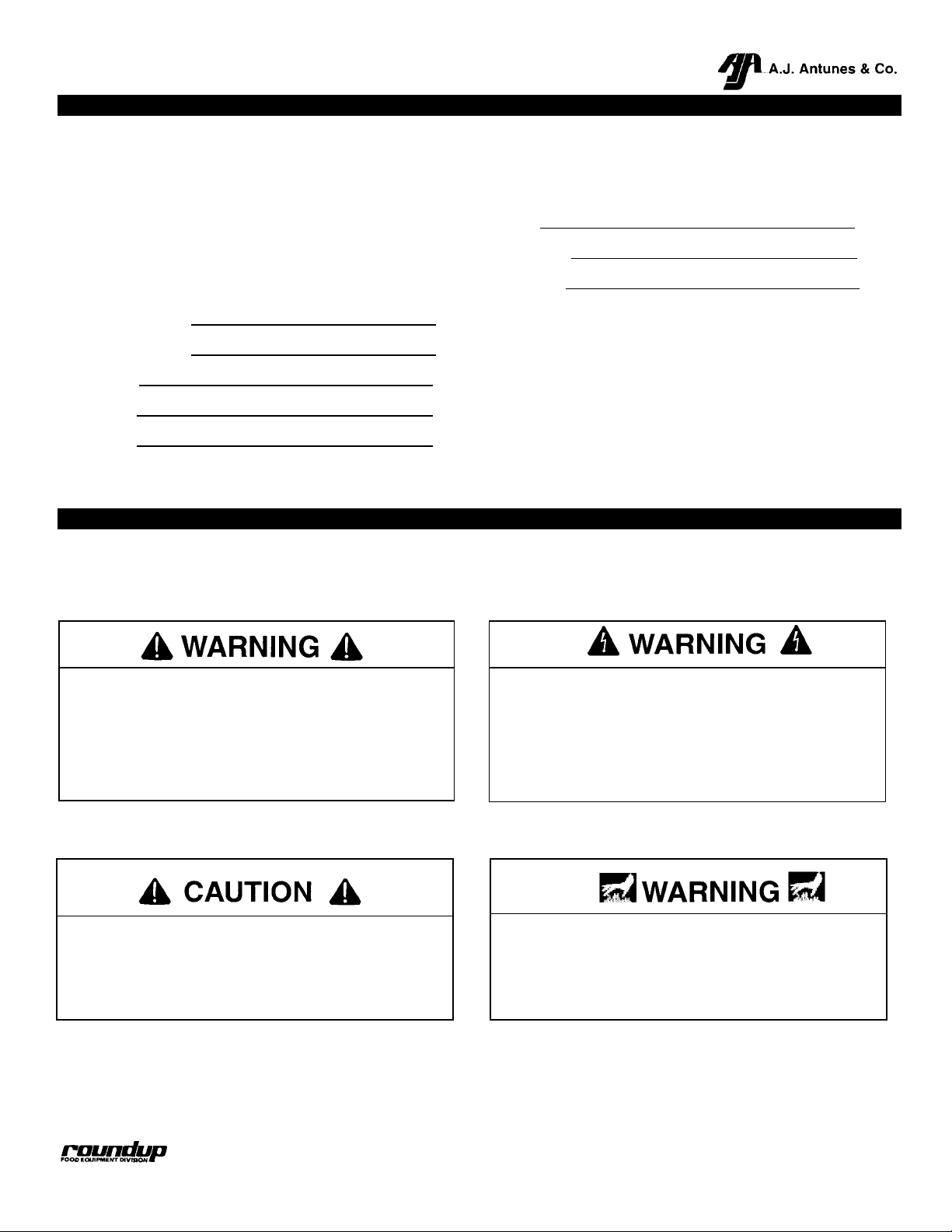
IMPORTANT SAFETY INFORMATION
Throughout this manual, you will find the following safety words and symbols that signify important safety issues with
regards to operating or maintaining the equipment.
GENERAL WARNING. Indicates information important to the proper operation of
the equipment. Failure to observe may
result in damage to the equipment and/or
severe bodily injury or death.
ELECTRICAL WARNING. Indicates information relating to possible shock hazard.
Failure to observe may result in damage to
the equipment and/or severe bodily injury
or death.
GENERAL CAUTION. Indicates information
important to the proper operation of the
equipment. Failure to observe may result in
damage to the equipment.
HOT SURFACE WARNING. Indicates
information important to the handling of
equipment and parts. Failure to observe
caution could result in personal injury.
2 P/N 1010598 Rev. B 7/99
Page 4

In addition to the warnings and cautions in this manual,
P/N
1010598
Rev. B
7/99
3
use the following guidelines for safe operation of the
unit.
• Read all instructions before using equipment.
• For your safety, the equipment is furnished with a
properly grounded cord connector. Do not attempt
to defeat the grounded connector.
• Install or locate the equipment only for its intended
use as described in this manual. Do not use
corrosive chemicals in this equipment.
• Do not operate this equipment if it has a damaged
cord or plug, if it is not working properly, or if it has
been damaged or dropped.
• This equipment should be serviced by qualified
personnel only. Contact the nearest Roundup
authorized service facility for adjustment or repair.
• Do not block or cover any openings on the unit.
• Do not immerse cord or plug in water.
• Keep cord away from heated surfaces.
• Do not allow cord to hang over edge of table or
counter.
The following warnings and cautions appear
throughout this manual and should be care fully
observed.
• Turn the unit off, disconnect the power source
and allow unit to cool down before performing
any service or maintenance on the unit.
• The procedures in this chapter may include the
use of chemical products. These chemical
products will be highlighted with bold face
letters followed by the abbreviated HCS (Hazard
Communication Standard). See Hazard
Communication Standard manual for the
appropriated Material Safety Data Sheets
(MSDS).
• The unit should be grounded according to local
electrical codes to prevent the possibility of
electrical shock. It requires a grounded
receptacle with separate electrical lines, protected by fuses or circuit breaker of the proper
rating.
• All electrical connections must be in accordance with local electrical codes and any other
applicable codes.
SAUSAGE CORRAL
• WARNING ELECTRICAL SHOCK HAZARD.
FAILURE TO FOLLOW THESE INSTRUCTIONS
COULD RESULT IN SERIOUS INJURY OR
DEATH.
- Electrical ground is required on this appliance.
- Do not modify the power supply cord plug. If
it does not fit the outlet, have a proper outlet
installed by a qualified electrician.
- Do not use an extension cord with this
appliance.
- Check with a qualified electrician if you are in
doubt as to whether the appliance is properly
grounded.
• This equipment is to be installed to comply with
the basic plumbing code of the Building
Officials and Code Administration, Inc. (BOCA)
and the Food Service Sanitation Manual of the
Food and Drug Administration (FDA).
• Do not clean this appliance with a water jet.
• Do not use a sanitizing solution or abrasive
materials. The use of these may cause damage
to the stainless steel finish.
• Chlorides or phosphates in cleansing agents
(e.g. bleach, sanitizers, degreasers or detergents) could cause permanent damage to
stainless steel equipment. The damage is usu ally in the form of discoloration, dulling of
metal surface finish, pits, voids, holes or
cracks. This damage is permanent and not
covered by warranty.
• The following tips are recommended for maintenance of your stainless steel equipment.
- Always use soft, damp cloth for cleaning,
rinse with clear water and wipe dry. When
required, always rub in direction of metal
polish lines.
- Routing cleaning should be done daily using
soap, ammonia detergent and water.
- Stains and spots should be sponged
using a vinegar solution as required.
- Finger marks and smears should be
rubbed off using soap and water.
Page 5
ble
codes.
Do not modify the power supply cord plug. If it
4 P/N
1010598
Rev. B
7/99
SAUSAGE CORRAL
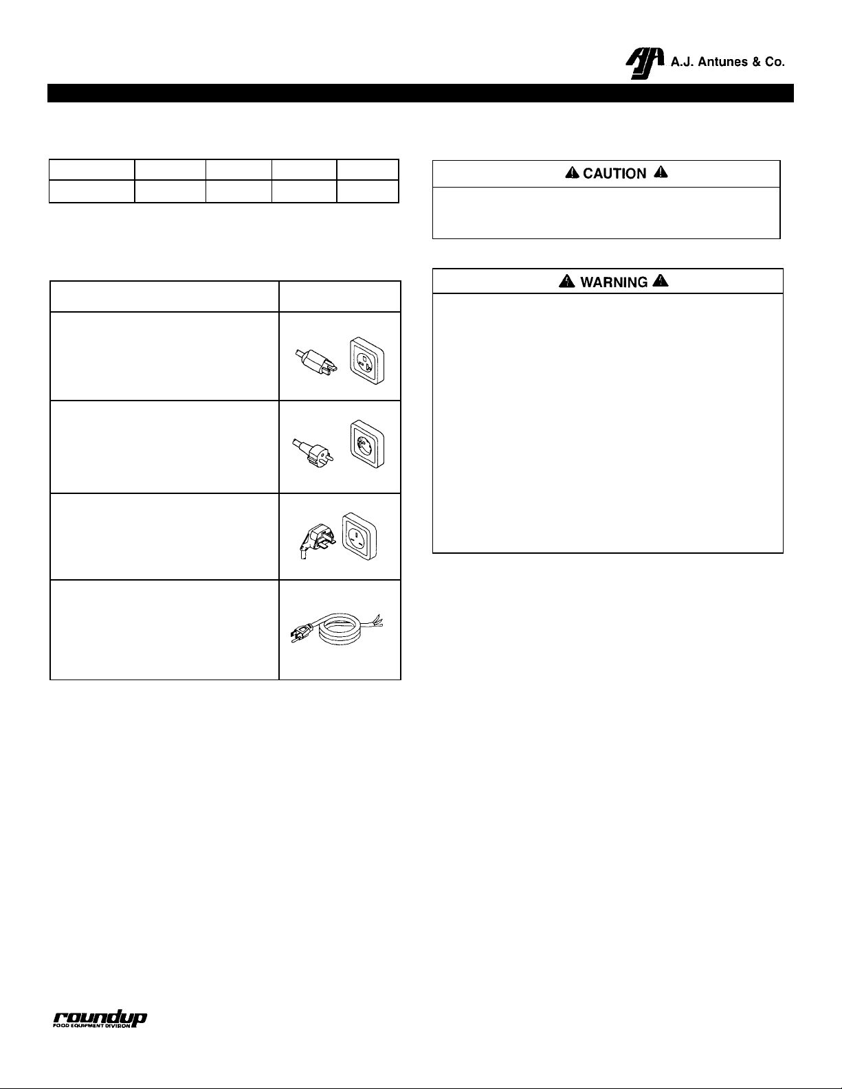
Electrical Ratings
Model Voltage Watts Amps Hertz
All 230 3400 14.8 50/60
Electrical Cord & Plug Configurations
Description Configuration
NEMA-6-20P
20 Amp, 230 VAC
CEE 7/7 Schuko
16 Amp, 250 VAC
BS-1363
13 Amp, 250 VAC
SPECIFICATIONS
All electrical connections must be in accordance
with local electrical codes and any other applica
FOLLOW THE INSTRUCTIONS IN THIS MANUAL
COULD RESULT IN SERI OUS INJURY OR DEATH.
• Electrical ground is required on this appliance.
•
does not fit the outlet, have a proper outlet
installed by a qualified electrician.
• Do not use an extension cord with this appliance.
• Check with a qualified electrician if you are in
doubt as to whether the appliance is properly
grounded.
Capacities (Refrigerated Product Only -Not Frozen)
ELECTRICAL SHOCK HAZARD. FAILURE TO
SC-20/25: Up to forty 5" sausages (127 mm) or twenty 7"
Commercial Cord
sausages (178 mm) or twenty 10" sausages (254 mm).
SC-40: Up to fifty 5" sausages (127 mm) or forty 7"
sausages (178 mm) or thirty 10" sausages (254 mm).
SC-25 (9300240): Special unit holds jumbo sausages.
Page 6

SAUSAGE CORRAL
P/N 1010598 Rev. B 7/99
Dimensions
Model Width (A) Depth (B) Height (C) Shipping Weight
27-1/8"
21-1/8"
5-15/16"
60 Ibs.
SC-20
(689 mm)
27-1/8"
(537 mm)
21-1/8"
(187mm)
5-15/16"
(27 kg)
60 Ibs.
SC-25
(689 mm)
33-3/8"
SC-40
(848 mm)
(537 mm)
21-1/8"
(537 mm)
(187mm)
5-15/16"
(187mm)
(27 kg)
67 Ibs.
(30.5 kg)
5
Page 7

SAUSAGE CORRAL
ble
codes.
P/N
1010598
Rev. B
7/99
6
INSTALLATION
Unpacking
1. Remove unit and all packing materials from shipping carton.
2. Open the large box. Remove all packing materials
and protective coverings from the unit and parts.
NOTE: If any parts are missing or damaged, contact An
tunes Technical Service IMMEDIATELY at 1-800-253-
2991.
3. Wash driver frame in soap and water.
On SC-20 & 25 models, remove the grease tray
and wash in soap and water.
Wipe all surfaces of the unit with a hot damp cloth.
NOTE: Do not use a dripping wet cloth. Wring out before
use.
4. Install driver frame onto unit.
Equipment Setup
When placing the unit into service, pay attention to the
following guidelines.
• Make sure power to the unit is off and the unit is at
room temperature.
• Do not block or cover any openings on the unit.
• Do not immerse cord or plug in water.
• Keep cord away from heated surfaces.
• Do not allow cord to hang over edge of table or
counter.
• Place unit on a sturdy, level table or work surface.
If unit is not level, adjust the legs clockwise to lower the
unit or counterclockwise to raise the unit.
Ensure that the line voltage corresponds to the stated
voltage on the unit specification label.
Turn off the rocker switch (power on/off). Connect the
unit to the power supply.
Figure 1. Sausage Corral (SC-20 Shown)
All electrical connections must be in accordance
with local electrical codes and any other applica
ELECTRICAL SHOCK HAZARD. FAILURE TO
FOLLOW THE INSTRUCTIONS IN THIS MANUAL
COULD RESULT IN SERIOUS INJURY OR DEATH.
• Electrical ground is required on this appliance.
• Do not modify the power supply cord plug. If it
does not fit the outlet, have a proper outlet
installed by a qualified electrician.
• Do not use an extension cord with this appli-
ance.
• The unit should be grounded according to local
electrical codes to prevent the possibility of
electrical shock. It requires a grounded receptacle with separate electrical lines, protected by
fuses or circuit breaker of the proper rating.
• Check with a qualified electrician if you are in
doubt as to whether the appliance is properly
grounded.
Page 8

SAUSAGE CORRAL
OPERATION
General
Figure
2.
Controls
- SC-20 & SC-25
7
Volume, preference and experience will determine what
temperature setting is best for your operation. When
holding sausages for long periods of time, it is recommended to keep the setting between 150°- 160°F (66°- 71
°C). This may vary depending on the type of sausage
used and the production rate required. If appearance of
the sausage is deteriorating rapidly, reduce temperature
setting.
As the sausages turn in their own juices, they become
self-basting, searing in all of the natural flavor. Excess
juices are allowed to collect in the lower lip at the front of
the grill. These juices can be absorbed with a paper tower
and discarded.
NOTE: Models SC-20 & SC-25 have a built-in grease tray
to collect cooking juices.
NOTE: The driver frame will accommodate almost any
diameter size sausage up to 1-1/4" (31.8 mm).
Operating Instructions
1. Turn the rocker switch (power on/off) to the ON
position.
2. Set the thermostat controls to the desired setting.
NOTE: Sausage Corrals have two separate heating
zones. Each zone is controlled by a separate thermostat.
3. Allow 10-15 minutes as a warm-up period, then
place the sausages in the driver frame assembly.
P/N 1010598 Rev. B 7/99
Figure 3. Controls – SC-40
Page 9

SAUSAGE CORRAL
and not covered by warranty. The following tips are
8 P/N
1010598
Rev. B
7/99
MAINTENANCE
Chlorides or phosphates in cleaning agents (e.g.
bleach, sanitizers, degreasers or detergents) could
cause permanent damage to stainless steel
equipment. The damage is usually in the form of
discoloration, dulling of metal surface finish, pits,
voids, holes or cracks. This damage is permanent
recommended for maintenance of your stainless
steel equipment:
• Always use soft, damp cloth for cleaning, rinse
with clear water and wipe dry. When required,
always rub in direction of metal polish lines.
• Routine cleaning should be done daily using
soap, ammonia detergent and water.
• Stains and spots should be sponged using a
vinegar solution.
• Finger marks and smears should be rubbed off
using soap and water.
• Hard water spots should be sponged using a
vinegar solution.
Do not use a sanitizing solution or abrasive mate rials. The use of these may cause damage to the
stainless steel finish.
Cleaning
The unit requires a minimum amount of maintenance. To
ensure proper operation, clean the unit after every use.
1. Remove driver frame and wash in hot detergent
water using a soft brush. Rinse in clear water.
On SC-20 & SC-25 models, remove the grease tray
and dispose of grease according to your local
procedures. Wash tray in hot detergent water using
a soft brush. Rinse in clear water and allow to air
dry.
2. The flat grill surface can be easily cleaned with a
clean, wet cloth.
3. Wash cooking surface with a sudsy cloth and rinse
with clean, wet cloth.
Turn the unit off, disconnect the power source and
allow the unit to cool down before performing any
service or maintenance on the unit.
Page 10

SAUSAGE CORRAL
Inspecting and Aligning Drive Parts
9
If the drive frame does not move smoothly, inspect and
align the drive parts as follows:
1. Turn the rocker (power on/off) switch to the OFF
position and unplug the unit.
2. Remove the right side panel cover.
3. Place a straightedge on the outside surface of the
pivot arm and motor arm (Figure 5). There should
be no gap between the motor arm and the
straightedge.
4. To remove any gap, loosen the setscrews on the
pivot arm and motor arm (Figure 4).
5. Tighten pivot arm setscrew. Allow 3/32" (2.5 mm) of
in/out motion on the crossover shaft/arm when
tightening setscrew. This will compensate for
expansion in the parts.
Failure to allow room for drive parts expansion can
cause binding during operation and may cause
early motor failure .
6. Place the straightedge on the outer surface of the
pivot arm and motor arm. Position the motor arm
until no gap exists as shown in Figure 5.
7. Tighten motor arm setscrew.
NOTE: Be sure setscrews are resting on the flat surface
of the shafts when tightening.
8. If drive frame still does not move freely, loosen
setscrew and remove motor arm from motor shaft.
Grasp both slide bracket pins and move back and
forth to try and determine the source of the bind. If
may be necessary to adjust the height of the slide
bracket.
Figure 4. Drive Components
Figure 5. Aligning Drive Components
NOTE: If any drive parts are replaced, repeat steps 1-8.
Inspect the drive rollers, bearings and retaining
rings for wear and replace if necessary.
P/N 1010598 Rev. B 7/99
9. Reinstall right side panel cover.
Page 11

SAUSAGE CORRAL
10 P/N 1010598 Rev. B 7/99
TROUBLESHOOTING
To avoid possible personal injury and/or damage to the unit, inspection, test and repair of electrical equipment
should be performed by qualified service personnel. The unit should be unplugged when servicing.
Problem Possible Cause Corrective Action
Unit will not heat up. Rocker
switch (power on/off) is on.
Power cord not plugged in. Plug power cord into outlet.
Circuit breaker is off or has been
Turn on or reset circuit breaker.
tripped in main power supply.
Thermostats not turned on. Turn thermostats to proper setting.
Loose connections. Check wiring continuity. Tighten as needed.
Defective wiring. Replace defective wires.
Defective power cord. Check power cord continuity. Replace if
necessary.
Defective rocker switch (power on/off). If there is power to the switch in the ON
position but no power coming out, replace
switch.
The driver frame does not
move smoothly.
The driver frame does not
move. Unit gets hot.
The driver frame scratches
the grill surface or slide
panels.
Defective thermostat. Replace thermostat.
Defective heating element(s). Replace heating element(s).
Driver frame out of square. Repair or replace driver frame.
Driver rollers or ratchet fasteners are
missing or need lubrication.
Install new driver rollers or ratchet fasteners or
lubricate with a small amount of food grade
grease.
Drive mechanism bent or damaged. Replace bent or damaged components.
Improper drive alignment. See Inspecting and Aligning Drive Parts
(page 9).
Defective motor. Replace motor.
Loose or damaged drive component or
loose setscrew.
Locate component and refasten or replace.
Tighten setscrew.
Defective motor. Replace motor.
Insulation contacting motor fan blade Remove base plate and replace insulation
under insulation retainer.
Drive frame is out of square, bent or
Replace driver frame.
damaged.
Page 12

SAUSAGE CORRAL
P/N 1010598 Rev. B 7/99
WIRING DIAGRAMS
11
Page 13

SAUSAGE CORRAL
12
REPLACEMENT PARTS (continued)
SC-20/25
P/N 1010598 Rev. B 7/99
Page 14

Item Part Description Qty.
Qty.
1 0020987
Driver Frame Weldment (SC
-
20) 1 26
3030117
Dowel Pin
2
P/N 1010598 Rev. B 7/99
SAUSAGE CORRAL
SC-20/25
Item Part Description
No.
2 0100195 Platen, Split Grill 2 27 0502767 Frame, LH 1
3 4000153 Drive Motor, (Incl. #52) 1 28 0800286 Shaft, Crossover 1
4000162 Drive Motor w/o Fan Blade 1 29 1000916 Label, Control Panel, LH 1
4 0020982 Housing, Side 2 30 0021157 Driver Frame Weldment (SC-25) 1
5 0020625 Slide Channel Assy. 2 0021225 Driver Frame Weldment Special
6 0502772 Panel, Cover 2 (SC-25-9300240) 1
7 210K12 Adjustable Leg Kit 31 0021196 Guide Rod Weldment (SC-25) 1
(Incl. Qty. 4 legs and #8 1 32 2100263 Thumb Screw, #10-32 x 1/2"
8 210K10 Foot, Rubber (Qty. 4) 1 (SC-25) 2
9 0502768 Frame, RH 1 33 218P113 Fastener, Ratchet, Black 1
10 0400282 Insulation, Heater 2 34 310P140 Washer, Flat, #10 1
11 0502773 Retainer, Insulation 6 35 310P162 Screw, #10-24 x 3/8" 1
12 403K10 Thermostat Kit, 250°F (Incl. 1 36 308P103 Screw, #8-32 x 1/4" 1
403K28 Thermostat Kit, 200°C (Incl. 1 37 306P104 Screw, #6-32 x 1/4" 1
403K15 Thermostat Kit, 400°F (Incl. 1 38 306P123 Screw, #6-32 x 7/8" 1
13 4010137 Rocker Switch, Power On/ Off 2 39 040P147 Bushing, Short, 7/8" 1
14 2100130 Knob, Thermostat, 0-250°F 1 40 308P124 Screw, #8-32 x 1/4" 1
2100233 Knob, Thermostat, 0-200°C 1 41 308P143 Nut, KEPS, #6-32 1
2100232 Knob, Thermostat, 0-400°F 1 42 0020625 Slide Channel Assy. 2
15 4060229 Indicator Light 2 43 0800286 Shaft, Crossover 1
16 0502769 Support, Center 1 44 2100129 Roller, Drive 2
17 0502770 Panel, Bottom 1 45 05K1705 Motor Arm w/Setscrew 1
18 1000915 Label, Control Panel, RH 1 46 080K217 Driver Arm Kit 1
19 0502771 Tray, Grease 1 47 05K1706 Pivot Arm w/Setscrew 1
20 0502844 Bracket, Center 2 48 310P146 Nut, KEPS, #10-32 1
21 0700452 Power Cord, NEMA 6-20P Plug 1 49 0300101 Screw, Pivot Shoulder 2
0700453 Power Cord, CEE 7/7 Plug 1 50 040K108 Bushing/Bearing Kit 1
22 4060304 Terminal Block 1 51 325P166 Setscrew, 1/4-28 x 3/8" 2
23 040K25 Strain Relief Kit 1 52 4000157 Fan Blade 1
24 0502738 Bracket, Cord 1 * Only availab le in quantities of 10.
25 0502843 Fascia, Platen 2
No.
13
Page 15

14 P/N 1010598 Rev. B 7/99
SAUSAGE CORRAL
REPLACEMENT PARTS (continued)
Page 16

Item Part Description Qty.
Item Part Description Qty.
15
SAUSAGE CORRAL
No.
1 0020983 Driver Frame Weldment,
0021064 Driver Frame Weldment,
2 0100195 Platen, Split Grill 2
3 4000153 Drive Motor, (Incl. #19) 1
4000162 Drive Motor w/o Fan Blade 1
4 0020982 Housing, Side 2
5 0020625 Slide Channel Assy. 2
6 0502772 Panel, Cover 2
7 210K122 Adjustable Leg Kit
8 210K108 Foot, Rubber (Qty. 4) 1
9 0502730 Angle Bracket, Slide 2
10 0400281 Insulation, Heater 1
11 0502735 Retainer, Insulation 3
12 403K108 Thermostat Kit, 250°F (Incl. #14) 1
403K287 Thermostat Kit, 200°C (Incl. #14) 1
403K159 Thermostat Kit, 400°F (Incl. #14) 1
13 4010137 Rocker Switch, Power On/Off 2
14 2100130 Knob, Thermostat, 0-250°F 1
2100233 Knob, Thermostat, 0-200°C 1
2100232 Knob, Thermostat, 0-400°F 1
15 4060229 Indicator Light 2
16 0502730 Panel, Front 1
17 0502734 Panel, Bottom 1
18 0502731 Control Panel 1
P/N 1010598 Rev. B 7/99
10 Spaces 1
9 Spaces 1
(Incl. Qty. 4 legs and #8 1
SC-40
No.
19 4000157 Fan Blade 1
20 0700452 Power Cord, NEMA 6-20P Plug 1
0700453 Power Cord, CEE 7/7 Plug 1
21 4060304 Terminal Block 1
22 040K251 Strain Relief Kit 1
23 0502738 Bracket, Cord 1
24 1000914 Label, Control Panel 1
25 218P113* Fastener, Ratchet, Black 1
26 310P140* Washer, Flat, #10 1
27 310P162* Screw, #10-24 x 3/8" 1
28 308P103* Screw, #8-32 x 1/4" 1
29 306P104* Screw, #6-32 x 1/4" 1
30 306P123* Screw, #6-32 x 7/8" 1
31 040P147* Bushing, Short, 7/8" 1
32 308P124* Screw, #8-32 x 1/4" 1
33 308P143* Nut, KEPS, #6-32 1
34 0020625 Slide Channel Assy. 2
35 0800283 Shaft, Crossover 1
36 2100129 Roller, Drive 2
37 05K1705 Motor Arm w/Setscrew 1
38 080K217 Driver Arm Kit 1
39 05K1706 Pivot Arm w/Setscrew 1
40 310P146* Nut, KEPS, #10-32 1
41 0300101 Screw, Pivot Shoulder 2
42 040K108 Bushing/Bearing Kit 1
43 325P166* Setscrew, 1/4-28 x 3/8" 2
* Only available in quantities of 10.
 Loading...