

Page 1
Mini Radiant Toaster
Model RT-2
Mfg. Number
9210906
Radiant Toaster
EQUIPMENT
www.antunes.com
P/N 1011309 Rev. B 04/17
Page 2
CONTENTS
General ...................................................... 2
Warranty
Information ............................................... 2
Service/Technical
Assistance ..................................................2
Important Safety
Information ............................................... 3
Warnings ...................................................3
Specications ............................................ 4
Installation ................................................ 5
Operating
Instructions ............................................... 6
Toasting Product ................................................6
Adjusting Toast Quality ....................................7
Purging product ................................................7
Factory Reset .......................................................7
Toaster Settings .................................................. 8
Shutting down the Toaster .............................8
Hi Limit Reset Button ........................................8
Maintenance .............................................8
Daily Maintenance .............................................8
Quarterly Maintenance ....................................9
Error Messages..........................................9
Cleaning the Fans ............................................ 10
Adding/Removing Conveyor Belt Chain
Links ..................................................................... 11
Replacing the Conveyor Belt Chain. ......... 11
Troubleshooting .....................................12
Replacement Parts..................................13
Wiring Diagram .......................................18
Limited Warranty ....................................20
IMPORTANT
A.J. Antunes & Co. reserves the right to
change specications and product de-
sign without notice. Such revisions do not
entitle the buyer to corresponding changes,
improvements, additions or replacements
for previously purchased equipment.
IMPORTANT
Keep these instructions for future refer-
ence. If the unit changes ownership, be sure
this manual accompanies the equipment.
GENERAL
This manual provides the safety, installation, and operating procedures for
your toaster. Please read all of the information contained in this manual prior
to installing and operating the toaster.
Your toaster is manufactured from the
nest materials available and is assembled to our strict quality standards.
This toaster was tested at the factory to
ensure dependable trouble-free operation.
WARRANTY
INFORMATION
Please read the full text of the Limited
Warranty in this manual.
If the unit arrives damaged, contact the
carrier immediately and le a damage claim with them. Save all packing
materials when ling a claim. Freight
damage claims are the responsibility
of the purchaser and are not covered
under warranty.
The warranty does not extend to:
y Damages caused in shipment or
damage as result of improper use.
y Installation of electrical service.
y Normal maintenance as
outlined in this manual.
y Malfunction resulting from
improper maintenance.
y Damage caused by abuse
or careless handling.
y Damage from moisture into
electrical components.
Damage from tampering with, removal
of, or changing any preset control or
safety device.
SERVICE/TECHNICAL
ASSISTANCE
If you experience any problems with
the installation or operation of your system, contact Antunes Technical Service
at +1-877-392-7854 (toll free).
Fill in the information in the next
column and have it handy when calling
for assistance. The serial number is on
the specication plate located on the
system.
Purchased From
Date of Purchase
Model Number
Serial Number
Mfg. Number
Use only genuine Antunes replacement
parts in this unit. Use of replacement
parts other than those supplied by the
manufacturer will void the warranty.
2
P/N 1011309 Rev. B 04/17
Page 3

IMPORTANT SAFETY
INFORMATION
Use the following guidelines for safe
operation of the unit.
y Read all instructions be-
fore using equipment.
y For your safety, the equip-
ment is furnished with a properly grounded cord connector. Do not attempt to defeat
the grounded connector.
y Install or locate the equip-
ment only for its intended use
as described in this manual.
Do not use corrosive chemicals in this equipment.
y Do not operate this equipment if
it has a damaged cord or plug, if
it is not working properly, or if it
has been damaged or dropped.
y This equipment should be
serviced by qualied personnel only. Contact your nearest
Authorized Service Agency
for adjustment or repair.
y Do not block or cover any
openings on the unit.
y Do not immerse cord
or plug in water.
y Keep cord away from
heated surfaces.
y Do not allow cord to hang over
edge of table or counter.
y Turn the power o, unplug the
power cord, and allow unit to cool
down before performing any service or maintenance on the unit.
y The equipment should be
grounded according to local
electrical codes to prevent the
possibility of electrical shock. It
requires a grounded receptacle
with separate electrical lines,
protected by fuses or circuit
breaker of the proper rating.
y All electrical connections must
be in accordance with local electrical codes and any
other applicable codes.
y Do not clean this appli-
ance with a water jet.
WARNINGS
Be advised of the following warnings
when operating and performing maintenance on this unit.
y If the supply cord is damaged, it
must be replaced by the manufacturer or its service agent or
a similarly qualied person
in order to avoid a hazard.
y Do not modify the power sup-
ply cord plug. if it does not t
the outlet, have a proper outlet
installed by a qualied electrician.
y Do not use an extension
cord with this appliance.
y Electrical ground is re-
quired on this appliance.
y Check with a qualied electrician
if you are unsure if the appliance is properly grounded.
y If a chemical cleaner is used, be
sure it is safe to use on cast aluminum. Observe all precautions
and warnings on product label.
y Inspection, testing, and re-
pair of electrical equipment
should only be performed by
qualied service personnel.
y This equipment is to be installed
to comply with the basic plumbing code of the Building Ocials
and Code Administrators, Inc.
(BOCA) and the Food Service
Sanitation Manual of the Food
and Drug Administration (FDA).
y Do not use abrasive materials.
The use of these may cause damage to the stainless steel nish.
y Chlorides or phosphates in clean-
ing agents (e.g. bleach, sanitizers,
degreasers or detergents) could
cause permanent damage to
stainless steel equipment. The
damage is usually in the form of
discoloration, dulling of metal
surface nish, pits, voids, holes, or
cracks. This damage is permanent
and not covered by warranty.
y The following tips are recom-
mended for maintenance of
your stainless steel equipment:
y Always use soft, damp cloth
for cleaning, rinse with clear
water and wipe dry. When
required, always rub in direction of metal polish lines.
y Routine cleaning should be
done daily with soap, ammonia detergent, and water.
y Stains and spots should be
sponged using a vinegar solution.
y Finger marks and smears
should be rubbed o using soap and water.
y Hard water spots should be
removed using a vinegar solution.
P/N 1011309 Rev. B 04/17
3
Page 4
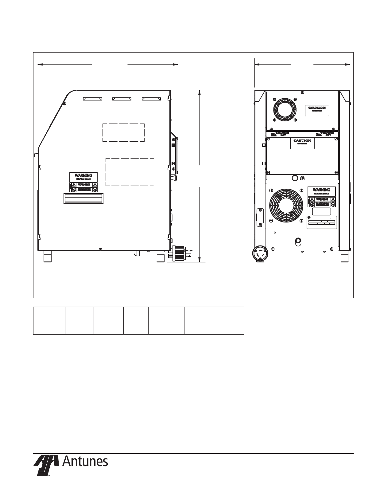
23.5”
(596.9 mm)
13”
(330.2 mm)
18.94”
(480.9 mm)
SPECIFICATIONS
Model Volts Watts Amps Hertz
9210906
RT-2
208~ 5000 24 50/60 L6-30P Twist Lock
Description
4
Plug
P/N 1011309 Rev. B 04/17
Page 5
INSTALLATION
NOTE: When placing the toaster
into service, make sure to
provide at least 3 inches of
space on all sides of the unit.
1. Remove unit and all packing materials from shipping
carton. The toaster is shipped
with the items listed below:
• Owner’s Manual
• Authorized Service Agency
Directory
NOTE: If any parts are missing or
damaged, contact Antunes
Customer Service IMMEDIATELY
at +1-877-392-7856.
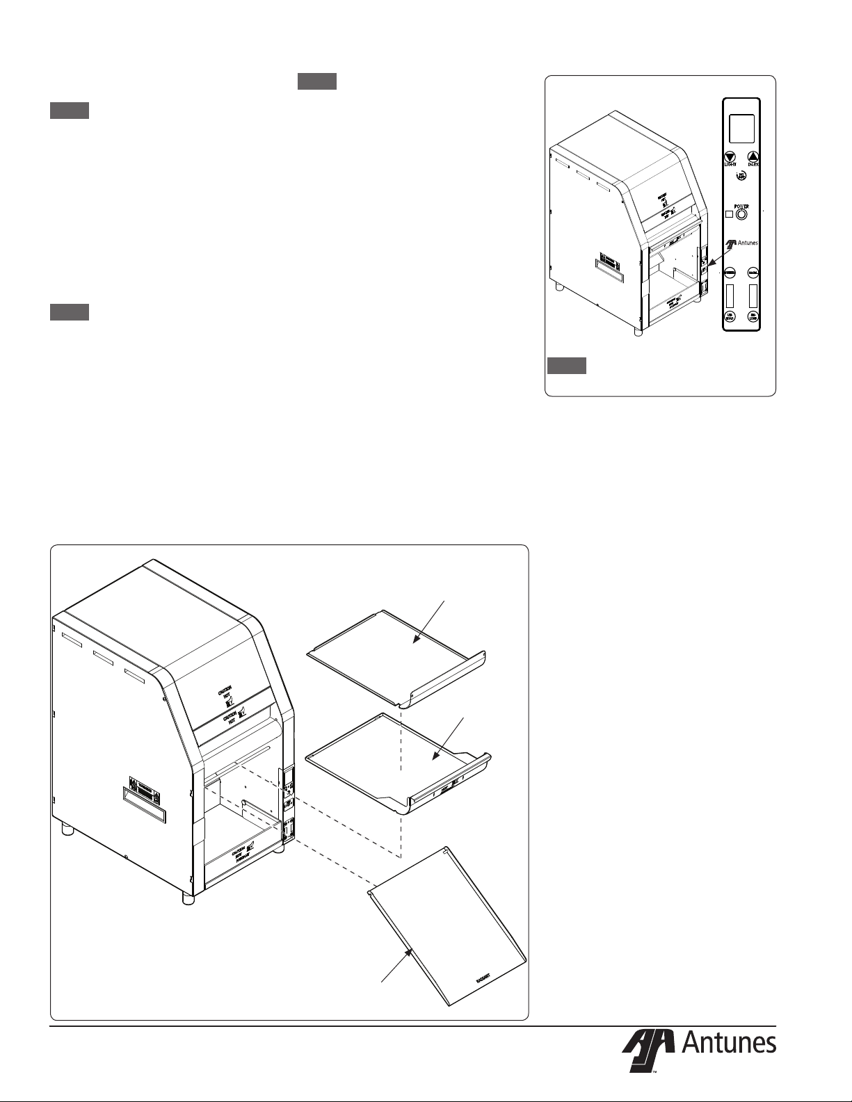
2. Remove all packing materials and protective coverings from the unit.
3. Refer to Figure 1. Crumb Tray
and the Bun Chute. Wash these
items at the 3 compartment
sink and set aside to air dry
4. Wipe all surfaces of the unit
with a hot damp cloth.
NOTE: Do NOT use a dripping wet
cloth. Wring out before use.
5. Re-install the Crumb
Tray and Bun Chute.
When placing the unit into service, pay
attention to the following guidelines.
y Make sure to provide at least 3
inches of space on both sides of
the unit and at least 6 inches from
the rear of the unit and the wall.
y Make sure the power switch
is o and the unit is at room
temperature before plugging in the power cord.
y Do not block or cover any
openings on the unit.
y Do not immerse the power
cord or plug in water.
y Keep the power cord away
from heated surfaces.
y Do not allow the power
cord to hang over edge
of table or counter.
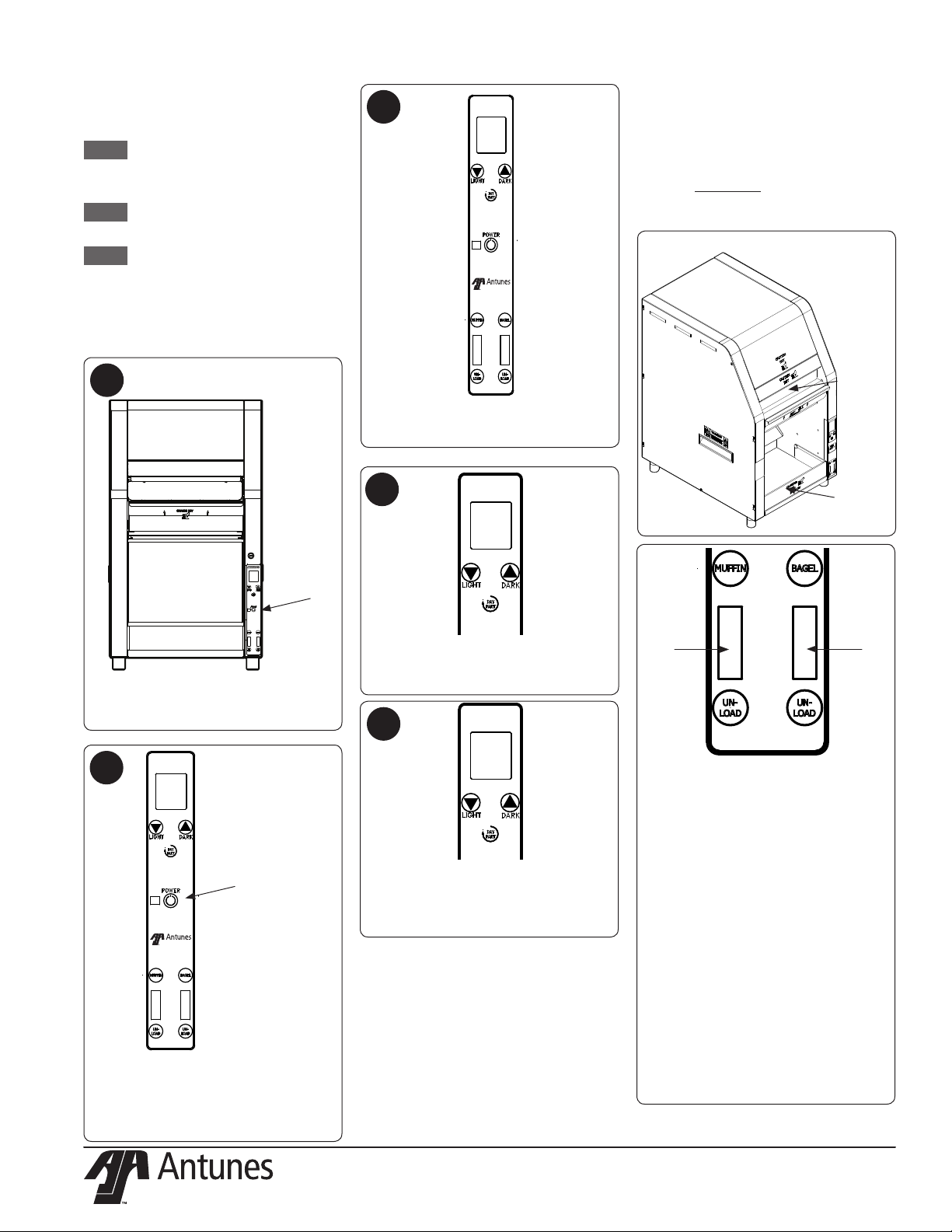
Figure 2
NOTE: The main Control Panel is
located on the front of the unit.
Figure 1
CRUMB TRAY
REFLECTOR
CRUMB TRAY
P/N 1011309 Rev. B 04/17
BUN CHUTE
5
Page 6
OPERATING
INSTRUCTIONS
NOTE: To ensure proper operation,
toast some test product
at the start of each day.
NOTE: The toaster is programmed to
start up in Breakfast mode.
NOTE: If the toasting quality
needs adjustment, refer
to Adjusting Toasting
Quality in the Operation
section of this manual.
1
3
The unit displays the software version
and starts to warm up (10 minutes) .
TOASTING PRODUCT
Facing the front of the unit, insert product as described.
Insert Muns and Bagels in the Feeder
with the cut side up.
Refer to the image below.
Insert
product here
CUT SIDE
UP
Power button.
Press to turn
on, press and
hold to turn off.
OFF is displayed on the screen when
the toaster is powered o.
2
Power button.
4
MUFFIN
BAGEL
WAIT
After the system check, the unit dis-
plays the Mun Bagel Wait message.
This means the unit is warming up.
5
The unit displays the Mun Bagel
Ready message when it reaches
proper operating temperature.
MUFFIN
BAGEL
READY
Product exits
toaster here
TIMER AREATIMER AREA
After inserting a mun or bagel into
the toaster, press the Mun or Bagel
button. This starts a timer that tracks
the length of time product is held in
the toaster. When you press the Mun
or Bagel button, a green light appears
in the timer area (above). Each mun
or bagel toasted should be tracked.
When that product is used, press the
appropriate unload button to reset the
timer.
On the front of the toaster, press the
Power button to turn the toaster on.
The unit makes a clicking sound. This
is normal.
y A green light in the timer means
the product can be used.
y A ashing green light means the
product is nearing end of usage.
y A steady red light means the
product should NOT be used.
6
P/N 1011309 Rev. B 04/17
Page 7

ADJUSTING TOAST QUALITY
The unit can be adjusted to provide a
lighter or more darkly toasted product.
Follow these steps to adjust toasting
quality.
PURGING PRODUCT
2
If you need to purge product from the
toaster, press and hold both the Light
and Dark buttons. The Purge message
appears on the display and the toaster
speeds up, purging the product.
1
MUFFIN
BAGEL
READY
Press the ▲ (Light) button or ▼
(Dark) button briey to view the cur-
rent setting. Press and hold the Light
or Dark button for 5 seconds to enter
edit mode.
Use the Light and Dark Arrow but-
tons to adjust the toasting quality to
darker or lighter respectively.
NOTE: The ▲ (Light) button
decreases toasting darkness.
The ▼ (Dark) button
increases toasting darkness.
When the toaster is set as desired,
release the buttons and the toaster will
beep and save the settings to memory.
NOTE: This setting is maintained
when the unit is powered o.
1
PURGE
FACTORY RESET
To reset the unit to the original factory
settings, follow these steps:
1. Turn the unit o.
2. Press and hold the ▲ (Light)
and ▼ (Dark) buttons together
while turning the unit on.
Continue holding the buttons.
3. When the unit displays Factory
Reset, release the buttons.
The unit is reset to the original factory
settings. See the section titled Toaster
Settings on the next page for a table
describing these settings.
P/N 1011309 Rev. B 04/17
7
Page 8

TOASTER SETTINGS
The following tables shows the recommended settings for the toaster:
Breakfast
Setting Value
IR Percent Upper 80%
IR Percent Lower 70%
Air 25%
Toast Color 563
SHUTTING DOWN THE TOASTER
Follow these steps to shut down the
toaster:
1. Press and hold the Power button.
2. The unit enters cool down mode
and displays OK to Clean. The
fans continue to run. The unit
shuts down completely when
this cool down mode completes.
HI LIMIT RESET BUTTON
A hi-limit control (rear of unit) turns
o power to the unit if it overheats. To
reset this Hi-Limit control:
1. Allow sucient time (10-15 minutes) for the unit to cool down
2. Remove the Hi-Limit control
cap at the rear of the unit.
3. Press the Hi-Limit Reset button.
4. Turn the unit on. Test the unit
by toasting some test product.
If the Hi-Limit continues to trip,
contact Antunes Technical Service at
+1-877-392-7854 for assistance.
HI LIMIT RESET
LOCATION
MAINTENANCE
WARNING
The unit will remain hot while it is cooling
down. Personal injury and burns may result
from touching the unit before it is nished
cooling down. Wear Heat Resistant Gloves.
DAILY MAINTENANCE
Cleaning the Accessories and Toaster
1. Turn the toaster o. The unit
enters a 20 minute cool down
mode and displays OK to Clean
when complete. The fans and
conveyors continue to run. The
cleaning mode continues for 20
minutes and shuts the unit down
automatically when complete.
NOTE: You do not need to wait
for the count down to
complete. Continue with
the cleaning steps as soon
as you see OK to Clean.
2. Refer to Figure 3. Remove Crumb Tray and Bun
Chute and set aside.
3. Wash the Crumb Tray and
Bun Chute in soap and water. Rinse with clean water and allow to air dry.
4. Wipe all surfaces of the unit
with a hot damp cloth.
NOTE: Do not use a dripping wet
cloth. Wring out before use.
5. Wipe the bun landing area
and Skirt Weldment with a
hot damp cloth (Figure 3).
6. Inspect the Conveyor Belt Chain
to ensure it is in good condition and is free of damage. If
the chain requires replacement,
refer to the section titled Replac-
ing the Conveyor Belt Chain.
7. Refer to the two images in
the next column. Make sure
that both the front and rear
Heat Damper Curtains are in
place. Install the curtains if
they are not in place. If they
are in place, inspect, but do
not remove, the front and rear
curtains. Replace them if they
are worn, damaged, or frayed.
8
P/N 1011309 Rev. B 04/17
Page 9

QUARTERLY MAINTENANCE
Perform the steps in the Daily Maintenance section of this manual.
Inspect Conveyor Belt Chain
Inspect the Conveyor Belt Chain to
ensure it is in good condition and is free
of damage.
Check the tension on the Conveyor Belt
Chain. If the belt is sagging signicantly or is dragging on the Crumb Tray
Reector, remove one or two links from
the chain. Refer to the section titled
Adding/Removing Conveyor Belt
Chain Links for instructions.
Measuring Conveyor Belt Chain
1. Turn the toaster o. The unit
enters a 20 minute cool down
mode and displays OK to Clean
when complete. The fans and
conveyors continue to run. The
cleaning mode continues for 20
minutes and shuts the unit down
automatically when complete.
2. Remove the Crumb Tray.
3. See the image below. Facing
the front of the toaster, locate the front Idler Shaft. The
Idler Shaft should be in the
middle of the oval cut out.
Rear of Oval
Cut-out
Middle of Oval
Cut-out
Front of Oval
Cut-out
Front
Idler
Shaft
Conveyor Belt Chain not shown for clarity.
If the shaft is towards the front, remove
a link.
If the shaft is towards the back, add a
link.
If the shaft is in the middle, no action is
needed.
If you need to add or remove a link,
refer to the section titled Adding/Re-
moving Conveyor Belt Chain Links in
this manual.
ERROR MESSAGES
If the toaster encounters an operating error, the unit displays FAULT and
beeps. When this happens:
1. Press the Day/Part button to
display the active error code.
2. Write down this error code and
refer to the Troubleshooting
section of this manual.
For assistance, call Antunes Technical Service at +1-877-392-7854.
Figure 3
SKIRT WELDMENT
BUN LANDING
AREA
BUN CHUTE
CRUMB TRAY
REFLECTOR
CRUMB TRAY
P/N 1011309 Rev. B 04/17
9
Page 10

CLEANING THE FANS
Top Fan Cleaning
1. Turn the toaster o. The unit
enters a 20 minute cool down
mode and displays OK to Clean
when complete. The fans and
conveyors continue to run. The
cleaning mode continues for 20
minutes and shuts the unit down
automatically when complete.
NOTE: Be sure to wait until the unit
shuts down before proceeding.
2. Facing the rear of the toaster,
remove the three screws
circled in the image below
with a Phillips head screwdriver. Set the screws aside.
4. Clean the cooling fan with a
small plastic brush or a clean
dry cloth. Be sure to remove all
debris from the fan blades.
5. Close the Top Rear panel and
secure with the 3 screws.
6. Wipe the exterior portion
of the top fan with a clean,
damp towel. Make sure the
fan opening is clear of any
debris or obstructions.
Bottom Fan Cleaning
1. Refer to the image below.
Remove the top circled screw
and set aside. Then, loosen
but do not remove the 2
bottom circled screws.
3. Clean the bottom cooling fan with a small plastic
brush or a clean dry cloth.
Be sure to remove all debris from the fan blades.
4. Place the Bottom Rear panel
back into place, close the Rear
Door, and secure the Bottom Rear Panel with screws.
5. Wipe the exterior fan opening
with a clean, damp towel. Make
sure thee the fan opening is clear
of any debris of obstructions.
3. Rotate the Top Rear panel
down to gain access to
the top cooling fan.
REMOVE THIS
SCREW
LOOSEN THESE
SCREWS
2. Lift the Rear Door to open (image below) and then lift up the
Bottom Rear panel and rotate it
so the bottom fan is accessible.
10
P/N 1011309 Rev. B 04/17
Page 11

ADDING/REMOVING CONVEYOR
BELT CHAIN LINKS
Links from the Conveyor Belt Chain can
be removed or added to keep the Conveyor Belt Chain at the right tension.
1. Turn the toaster o. The unit
enters a 20 minute cool down
mode and displays OK to Clean
when complete. The fans and
conveyors continue to run. The
cleaning mode continues for 20
minutes and shuts the unit down
automatically when complete.
2. Remove the Crumb Tray
and Bun Chute.
3. Push the front of the Conveyor
Shaft in and down so it locks
into place. This removes tension
from the Conveyor Belt Chain.
Make sure both sides are locked
in the in and down position.
4. Locate the two Master
Links on the Conveyor
Belt Chain (Figure 4).
5. Remove the master link on
both the left and right side
of the chain using needlenose pliers. Flex the Master
Links to remove them and
set them aside temporarily.
6. Remove or add links as required.
7. Re-attach the Master Links
on both the left and right
side of the chain. This connects the two ends of the
chain together (Figure 5).
8. Lift the front of the Conveyor
up and out to restore tension
to the Conveyor Belt Chain.
9. Re-install the Crumb
Tray and Bun Chute.
10. Plug in the power cord
and turn the unit on.
1. Turn the toaster o. The unit
enters a 20 minute cool down
mode and displays OK to Clean
when complete. The fans and
conveyors continue to run. The
cleaning mode continues for 20
minutes and shuts the unit down
automatically when complete.
2. Remove the Crumb Tray
and Bun Chute.
3. Push the front of the Conveyor
Shaft in and down so it locks
into place. This removes tension
from the Conveyor Belt Chain.
Make sure both sides are locked
in the in and down position.
4. Locate the two Master
Links on the Conveyor
Belt Chain (Figure 4).
Figure 4
Figure 5
5. Remove the master link on
both the left and right side
of the chain using needlenose pliers. Flex the Master
Links to remove them.
6. Remove the existing Conveyor
Belt Chain and discard.
7. Refer to Figure 5 and install
the new Conveyor Belt Chain
around the sprockets.
8. Connect the two ends of the
Conveyor Belt Chain with the
Master Links (Figures 4 and 5).
9. Lift the front of the Conveyor
up and out to restore tension
to the Conveyor Belt Chain.
10. Re-install the Crumb
Tray and Bun Chute.
11. Plug in the power cord
and turn the unit on.
CRUMB TRAY
REFLECTOR
CRUMB TRAY
BUN CHUTE
REPLACING THE CONVEYOR BELT
CHAIN.
Before you replace the Conveyor Belt
Chain, make a note of how the existing chain is installed. The replacement
chain must be installed in the same
manner with the open end of the hooks
facing opposite of the direction of
travel (Figure 5).
P/N 1011309 Rev. B 04/17
DIRECTION
OF TRAVEL
MASTER
LINKS
11
Page 12

TROUBLESHOOTING
Problem Possible Cause Corrective Action
Power cord not plugged in Plug power cord into the proper electrical outlet
Hi-Limit has tripped
No Control Display
Conveyor does not turn on
Conveyor(s) hesitate
Crowns and/or Heels must be
forced into the toaster. Buns
sticking and burning.
Toaster making unusual sounds
Fans are making an unusual
sounds
Display reads “Hi-Limit Tripped”. Hi-Limit has tripped.
Display reads “Motor Running
Slow”.
Display Reads “High Intern
Temps.”
Display reads “Top IR Fault”
Display reads “Bottom IR Fault”
Display reads “Air Fault”
Display reads “Fault T/C”
Display reads “Overtemp”
Display reads “Conv Fan Fault” Upper Cooling Fan dirty or faulty.
Display reads “No Motor Found” Low voltage, check incoming power. Contact Antunes Technical Service at +1-877-392-7854.
Circuit breakers turned o or tripped. Damaged electrical outlet, plug, or cord. Power switch damaged
Faulty or misaligned communication cable Replace or align communication cable.
Faulty Transformer Replace transformer.
Conveyor Belt/Chain has stretched. Chain skipping on
sprockets.
Loose sprocket Verify setscrew is tight on at part of shaft.
Motor Drive Chain came o sprocket(s) Reinstall drive chain.
Internal part /object interfering within conveyor system Check for interference & clear up as necessary.
Dive chains need lubrication. Lubricate chain.
Loose or misaligned sprocket Align and tighten set screw on sprocket.
Motor drive chain loose or stretched Replace or tighten up slack on drive chain.
Drive motor(s) have failed Contact Antunes Technical Service at +1-877-392-7854.
Conveyor Belt/Chains are skipping on sprockets.
Drive motor stalls intermittently. Contact Antunes Technical Service at +1-877-392-7854.
Conveyor belt chains have stretched or adjusted incorrectly.
Motor Drive chain needs lubrication. Lubricate chain.
Conveyor shaft bearing is binding. Contact Antunes Technical Service at +1-877-392-7854.
Failed cooling Fans Verify vents on toaster are unblocked and not near other heating appliances.
Cooling Fans are dirty and need to be cleaned
A mechanical obstruction has occurred that is slowing
down the conveyor motor.
Wire Conveyor Belt is too loose/sagging & getting
jammed.
Wire Conveyor Belt is broken/damaged and jammed.
Toaster electrical compartment is overheating due to
the lack of airow surrounding the toaster.
Failed Heater or Solid State Relay.
Upper I/R Thermocouple faulty.
Allow unit to cool and reset the Hi-Limit Control. If it trips again, contact Antunes
Technical Service at +1-877-392-7854.
Reset circuit breakers. If they trip again, check the power cord,plug, and outlet for
damage. Contact Antunes Technical Service at +1-877-392-7854.
Measure and adjust the conveyor belt chains as described in the Maintenance
section of this manual.
Adjust the conveyor belt chains according to the Maintenance section of this
manual.
Adjust the conveyor belt chains as described in the Maintenance section of t his
manual.
Clean Fans. If error persists, contact Antunes Technical Service at +1-877-392-
7854.
Allow sucient time (10-15 minutes) for the unit to cool down. Remove the HiLimit control cap at the rear of the unit. Press the Hi-Limit Reset button. Turn the
unit on and test the unit by toasting some test product. If the Hi-Limit continues
to trip, contact Antunes Technical Service at +1-877-392-7854 for assistance.
Check the bottom wire conveyor and surrounding areas for any obstructions/
jams. Contact Antunes Technical Service at +1-877-392-7854.
If sagging is noticeable, remove the necessary links to shorten the Wire Conveyor
Belt. Refer to the Maintenance section in this manual. Contact Antunes Technical
Service at +1-877-392-7854.
Replace the wire belt according to the Maintenance section of this manual. Contact Antunes Technical Service at +1-877-392-7854.
Inspect the cooling at the top and at the bottom (back of unit) and ensure it is
clean according to the fan cleaning portion of the Maintenance section of this
manual. Make sure the unit has enough space on both sides and the rear of the
unit according to the Installation section of this manual. If the condition continues, contact Antunes Technical Service at +1-877-392-7854.
Contact Antunes Technical Service at +1-877-392-7854.
Inspect the cooling at the top and at the bottom (back of unit) and ensure it is
clean according to the fan cleaning portion of the Maintenance section of this
manual. Make sure the unit has enough space on both sides and the rear of the
unit according to the Installation section of this manual. If the condition continues, contact Antunes Technical Service at +1-877-392-7854.
12
P/N 1011309 Rev. B 04/17
Page 13

REPLACEMENT PARTS
Item Part No. Description Qty. Item Part No. Description Qty. Item Part No. Description Qty.
1 0012994 Assy, Bearing Cover 2
2 7001069 Curtain Assembly Kit 1
3 0013010 Back Panel Assembly 1
4 0013124 Contactor Bracket Assy 1
4a 0507182 Ele Mt Bracket 1
4b 3020133 Rivet, Plastic .026” - .062” 2
4c 3020134 Rivet, Snap W/ 7/16” Nylon Spacer 2
4d 3080203 Screw, Tap 8-32 X 3/8” W/Int.
Tooth Washer 2
4e 7001017 Contactor, 2 Pole NO 1
4f 4070227 Snubber Board 1
5 0021898 Wldmnt, Bearing Brkt &
Spring Guide - Rh 1
6 0021899 Wldmnt, Bearing Brkt &
Spring Guide - Lh 1
7 0021967 Ramp Weldment 1
8 0021968 Top Coil Mt Wldmt 1
9 0021969 Main Coil Mt Weldment 1
10 0021970 Lower Heater Mt Weldment 1
11 0021971 Control Housing Wldmt 1
12 0021972 End Housing Weldment 1
13 0021973 Back Panel Wldmt 1
14 0021975 Skirt Weldment 1
15 0200327 Silicone Strip 6” 2
16 0200328 Silicone Strip 12” 2
17 0400147 Bushing, Shorty 7/8” 3
18 040P265 Bushing, Shorty 3/8” 18
19 0400414 Insulator, 1/2” Ceramic Female 6
20 0400459 Spacer, 1.125 Od X .25 Id X .03
Thk Nomex 6
21 0400463 Cover, Contactor 1
22 0400464 Cover, Motor Board 1
23 050K128 Bracket, Sensor 1
24 0506612 Plate, Tensioner 2
25 0506658 Retainer, Capillary Bulb 1
26 0506743 Access Cover One Fan 1
27 0506744 Plate, Top Housing 1
28 0506746 Bracket, Motor 1
29 0506747 Top Housing Radiant 1
30 0506748 Cover Channel End Housing 1
31 0506749 Cover Lower 1
32 0506750 Cover Channel Control Hsg 1
33 0506751 Cover Upper Coil 1
34 7001089 Tray, Crumb 1
35 0506772 Reector, Rh 1
36 0506773 Reector, Lh 1
37 0506785 Wall Cool 1
38 0506786 Bun Ramp 1
39 0506789 Control Housing Panel 1
40 0506790 End Housing Panel 1
41 0506791 Heater Cover 1
42 0506792 Heater Base 1
43 0506799 Retainer, Bearing 2
44 0507073 Bracket, Usb Mounting 1
45 0507162 Bezel, Label Retainer 1
46 0507175 Retainer, Heater Element 8
47 0507181 Retainer, Heater Element 4
48 0507193 Shield, Reector 2
49 0507194 Cover, Usb 1
50 0507198 Reector, Crumb Tray 1
51 0600141 Spring, Compression 2
52 0800444 Connecting Link, Chain 2
53 0800463 Rod 1/4 X 10 Inch 2
54 0800464 Rod 3/8 X 10 Inch 1
55 7001010 Conveyor Kit 1
56 1001548 Label, Control 1
57 21000-0046 Stando, 1/4” Locking Pcb 4
58 2100212 Handle, Pocket Pull, Snap-In 2
59 210K230 Bumper, Recess W/Washer 4
60 2100334 Thrust Strip, Teon 2
61 211P195 Hose Clamp Pkg of 10 2
62 2110197 Clip, Steel Cable 1
63 2120143 Spacer, #4 X .25Lg 5
64 2120147 Spacer, Leg 4
65 2120249 Spacer, .115 Id X .25 Od .062
Thk Nylon 4
66 2150179 Sprocket, 25B14 1/2” Bore 1
67 7000224 Bearing and Retainer Kit 1
68 2150251 Sprocket, 25B14 3/8” Bore 1
69 2150254 Roller 4
70 7001004 Bearing Kit 2
71 2150277 Sprocket, Drive 17 Tooth 2
72 2150352 Shaft, Drive 1
73 2150353 Shaft, Idler 1
74 2150369 Drive Chain 1
75 218P145 Cover, Bumper 4
76 300P123 Ring, Retaining, External 1
77 3010101 Weld Nut-Twin #8-32 1
78 30400-0010* Nut, #4-40 Nylon 1
79 3040123* S crew, Mach #4-40 X 3/8” Panhd Phillips 1
80 306P130* Nut, Hex Keps #6-32 (Small Pattern) 1
81 308P101* Nut, Hex #8-32 1
82 308P115* Screw, Mach. #8-32 X 3/8” 1
83 308P193* Scr, Mach #8-32 X 1 1/4” Sltthd 1
84 308P203* Screw, Tap 8-32 X 3/8” W/Int.
Tooth Washer 1
85 308P227* Scr Mach #8-32 X 3/8” Hxhdsltd;
Shoulder 1
86 308P344* Stnd-O #8-32 X 3/8 M/F 1
87 310P108* Screw, Mach. #10-32 X 1/2” 1
88 310P110* Screw, Mach. #10-32 X 1/2” 1
89 310P146* Nut, Hex ‘Keps’ #10-32 1
90 310P180* Screw, Mach. #10-32 X 1-3/4” 1
91 310P187* Screw Set, #10-32 X 3/8 Hex
Socket-Cone Point 1
92 310P199* Scr, #10-32 X 3/8 Lg Socket Hd Cap 1
93 310P213* Screw, Phpnhd #10-16 X 3/4” Thrd Form 1
94 310P215* Scr, Shldr #10-32 X 1/4” W/1/4”
Shldr Precision 1
95 325P163* Set Screw, 1/4-28 X 5/16” 1
96 7001146 Fan Blower Kit 1
97 7000913 Fan Kit 1
98 7001041 Motor Kit 1
99 7001145 Transformer Kit 240 Vac/12Vac 1
100 4030332 Thermostat, Hi-Limit 1
101 4030438 Heater, Cfa 2
102 7001012 Heater Kit 1
103 4030440 Heater, Foil 208V, 50W 1
104 4050180 Heat Sink 2
105 4050234 Thermocouple, Type K (Open End) 1
106 7001143 Relay Kit 1
107 7001143 Relay Kit 1
108 7001090 Thermocouple Kit 1
109 4060234 Wire Strap - 3/8” 2
110 4060398 Terminal Block, S-Series 1
111 4060451 Usb, A-F Pnl Mount/A-M Shield 1
112 4070154 Varistor Board 1
113 7001040 Motor Board Kit 1
114 4070216 Current Sense Board 1
115 7001007 Control Board Kit 1
116 7001085 Main Board Kit 1
117 0400437 Strain Relief, Rt. Angle 1
118 0700479 Power Cord T/Lock L6-30P 1
*Available in packages of 10 (ten).
P/N 1011309 Rev. B 04/17
13
Page 14

18
47
18
46
113
46
47
46
17
60
24
51
14
92
98
14
34
18
84
20
20
67
40
58
43
89
66
91
84
70
20
6
1
67
95
89
68
74
28 57
84
14
P/N 1011309 Rev. B 04/17
38
50
Page 15

105
82
23
84
77
18
85
49
111
76
70
67
43
89
112
17
110
83
47
18
18
116
4556
78
115
78
62
84
108
46
20
24
60
46
18
20
47
46
5
67
25
84
46
18
20
84
51
84
1
89
39
58
P/N 1011309 Rev. B 04/17
15
Page 16

8
84
101
19
33
46
46
55
69
69
2
71
71
69
72
73
69
101
31
19
46
10
62
84
18
20
84
94
108
19
20
9
102
6161
19
18
47
25
47
20
94
18
32
25
84
94
16
P/N 1011309 Rev. B 04/17
Page 17

97
2
26
84
3
22
84
84
107
106
117
118
59
104
86
86
104
99
80
4d
4
4e
4b
4c
4f
4a
100
96
13
84
21
88
P/N 1011309 Rev. B 04/17
17
Page 18

WIRING DIAGRAM
18
P/N 1011309 Rev. B 04/17
Page 19

HEAT SINK
STAND-OFF
RELAY, RANDOM PHASE, SOLID STATE-50A
14
STAND-OFF
11
BLK
ORG
15
RED
CONN
FROM J11
RELAY, SOLID STATE DUAL POLE W/CONN-RECPT
12
08
06
09
05
BLK
BLK
BLK
BLK
BLK
P/N 1011309 Rev. B 04/17
19
Page 20

LIMITED WARRANTY
Equipment manufactured by A.J. Antunes & Co. has been constructed of the nest materials available and manufactured
to high quality standards. These units are warranted to be free from electrical and mechanical defects for a period of two (2)
years from date of purchase under normal use and service, and when installed in accordance with manufacturer’s recommendations. To insure continued operation of the units, follow the maintenance procedures outlined in the Owner’s Manual.
During the rst 12 months, electro-mechanical parts, non-overtime labor, and travel expenses up to 2 hours (100 miles/160
km), round trip from the nearest Authorized Service Center are covered. During the second year of this warranty (months 12
- 24), the following items are covered by a Part Only warranty: Drive Motor, Motor Board, Current Sense Board, Display Board,
and Main Board.
1. This warranty does not cover cost of installation, defects caused by improper storage or handling prior to placing of the Equipment. This warranty does not cover overtime charges or work done by unauthorized service
agencies or personnel. This warranty does not cover normal maintenance, calibration, or regular adjustments
as specied in operating and maintenance instructions of this manual, and/or labor involved in moving adjacent objects to gain access to the equipment. This warranty does not cover consumable/wear items such as
Release Sheets (if present), Conveyor Belt Chain Link removal, Belt Wraps, and Dampers. This warranty does
not cover damage to the Platen due to operating the toaster without a Release Sheet when required or cleaning with abrasive cleansers or tools, misuse or dropping of unit. This warranty does not cover problems or
failures resulting from improper/incorrect voltage supply. This warranty does not cover Travel Time & Mileage in excess of 2 hours (100 miles/160 km) round trip from the nearest authorized service agency.
2. A.J. Antunes & Co. reserves the right to make changes in design or add any improvements on any product. The right is always reserved to modify equipment because of factors beyond our control and government regulations. Changes to update equipment do not constitute a warranty charge.
3. If shipment is damaged in transit, the purchaser should make a claim directly upon the carrier. Careful inspection should be made of the shipment as soon as it arrives and visible damage should be noted upon the carrier’s receipt. Damage should be reported to the carrier. This damage is not covered under this warranty.
4. Warranty charges do not include freight or foreign, excise, municipal or other sales or
use taxes. All such freight and taxes are the responsibility of the purchaser.
5. This warranty is exclusive and is in lieu of all other warranties, expressed or implied, including any implied warranty or merchantability or tness for a particular purpose, each of which is hereby expressly disclaimed. the remedies described above are exclusive and in no event shall A.J. Antunes & Co. be liable for
special consequential or incidental damages for the breach or delay in performance of this warranty.
+1 (630) 784-1000
+1 (800) 253-2991
+1 (630) 784-1650
+86-512-6841-3637
+86-512-6841-3907
 Loading...