

Page 1

180 Kehoe Blvd.
Carol Stream, Illinois 60188 USA
1-630-784-1000 (Tech Service).
MT-12 TECHNICAL MANUAL
LAST UPDATE 2-15-05
1060004 2/05
Page 2
MT-12
Muffin
Toaster
Training
MT-12 TECHNICAL MANUAL
LAST UPDATE 2-15-05
1060004 2/05
Page 3
MT-12 Muffin Toaster
•Warranty
•Toaster warnings
•Toaster installation
•Theory of operation
•Operation instructions
•Toaster maintenance
•Trouble shooting
•Parts Testing & Replacement
procedures
•Wiring Diagram
•Specifications
(Refer to Manual P\N 1010610).
MT-12 TECHNICAL MANUAL
LAST UPDATE 2-15-05
1060004 2/05
Page 4

LIMITED WARRANTY
The Antunes Food Service Equipment Division of A.J. Antunes & Co. provides the following limited warranty to the original purchaser
of all McDonald Equipment manufactured and purchased after January 1, 2003.
All components are warranted against defects in the material and workmanship for a period of two (2) years from date of original
installation, not to exceed 30 month from date of shipment from our factory .
If any part becomes defective during the first two (2) years after the original Installation date, Antunes Food Service will pay
negotiated straight time labor costs to an Authorized Service Agent to replace the part, plus travel expenses up to 50 miles/80 km,
1 hour each way (100 miles/ 160 km, 2 hours round trip).
WARRANTY EXCLUSIONS:
•The cost of Installation.
•Equipment that has been damaged due to shipment.
Purchaser should make damage claim directly upon carrier
•Alteration, misuse, abuse.
•Improper storage or handling.
•Improper maintenance.
•Failure to follow proper Installation instructions, including
electrical connection.
•Improper or unauthorized repairs.
Antunes Food Service reserves the right to make changes in design or add improvements on any products. The right Is always
reserved to modify Equipment because of factors beyond our control and government regulation. Changes to Equipment do not
constitute a warranty charge.
This warranty is exclusive and is in lieu of all other warranties, expressed or Implied, including any Implied warranty of
merchantability or fitness for a particular purpose, each of which is expressly disclaimed. The remedies described above are
exclusive, and in no event shall A.J. Antunes & Co. or any of its Divisions be liable for special consequential or Incidental damages
for the breach or delay in the performance of this warranty
•Scheduled Maintenance procedures as outlined in your MRC Card.
•Consumables such as Grill Covers (Release Sheets), gaskets, Conveyor Belt
Wraps, O’Rings, and light bulbs.
•Overtime or Holiday charges.
•Mileage over 50 miles/80 km (100 miles/160 km round-trip), or travel time
over two (2) hours.
•Freight, foreign, excise, municipal or other sales or use taxes.
•Consequential damages such as loss of profit, loss of time, the cost of
repairing or replacing other property which is damaged, or any other
incidental damage of any kind.
MT-12 TECHNICAL MANUAL
LAST UPDATE 2-15-05
1060004 2/05
Page 5
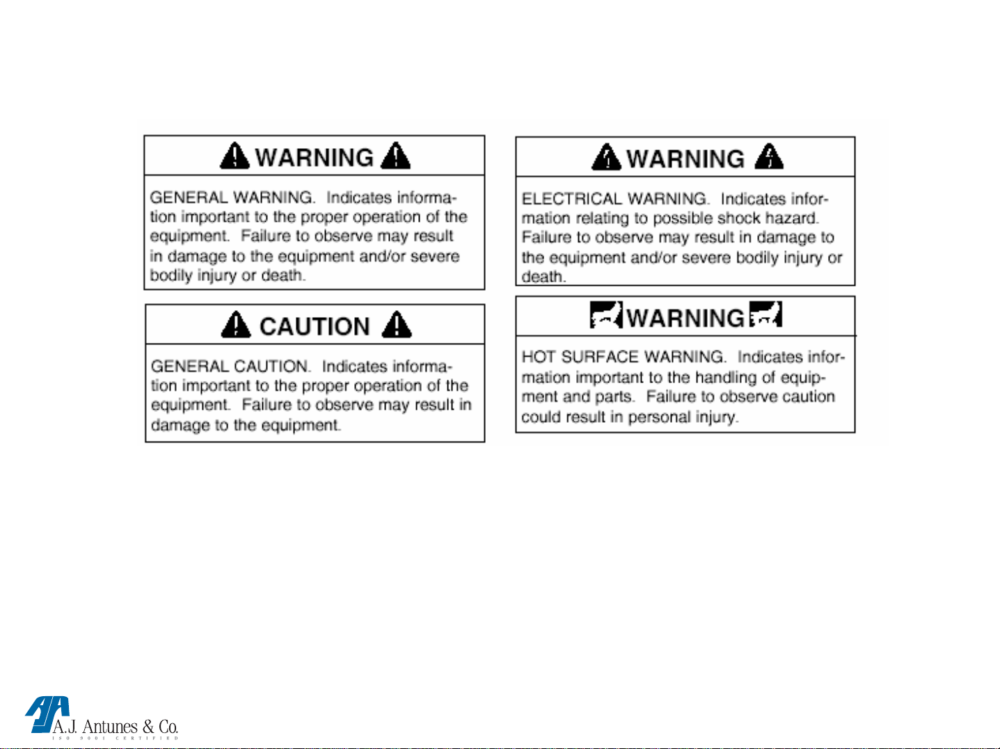
WARNING
To avoid possible injury and/or damage to the unit, inspection, test and repair of electrical
equipment should be performed by QUALIFIED SERVICE PERSONNEL. The unit should be
unplugged when servicing, except when electrical tests are required. Use extreme care during
electrical circuit tests. Live circuits will be exposed.
MT-12 TECHNICAL MANUAL
LAST UPDATE 2-15-05
1060004 2/05
Page 6

WARNING
WARNING
If the supply cord is damaged, it must be
replaced by the manufacturer or its service
agent or a similarly qualified person in
order to avoid a hazard.
WARNING
WARNING
WARNING
WARNING
Do not use an extension cord with this
appliance.
WARNING
WARNING
Do not modify the power supply cord plug
if it does not fit the outlet, have a proper
outlet installed by a qualified electrician.
MT-12 TECHNICAL MANUAL
LAST UPDATE 2-15-05
Check with a qualified electrician if you
are in doubt whether the appliance is
properly grounded or not.
WARNING
WARNING
Do not clean this appliance with a water
jet.
1060004 2/05
Page 7
MT-12 TECHNICAL MANUAL
LAST UPDATE 2-15-05
1060004 2/05
Page 8

TECHNICAL THEORY OF OPERATION
MT-12
When the power switch is turned on, line voltage flows to the blower motor & the primary side of
the step down transformer (Terminals 1 & 5). This transformer has 2 secondary output coils. The
two top terminals, 6 & 7 (Black wires) supply 10-12 VAC. The two bottom terminals, 9 & 10
(Brown wires) supply 6-8 VAC to the control board input terminal P1. During the power up
sequence, the unit performs a self test. Two (2) beeps, not followed by any additional beeps
indicate a successful test. If certain faults were detected, the unit will begin to beep 2-5 times wit h
a 2 second pause between beeps (See Beep Codes).
This control board has 2 modes of operation, Standby Mode & Toast Mode. In Standby Mode
(Unit Idling), the heater assembly, which consists of a left & right side coil, will partially heat to
maintain the toast chamber hot. It generates approximately 4-6 fluctuating amps during standby. Its
voltage will also fluctuate between 0-50 VAC when measured with a VOM across the SS relay
output terminals A2 & B2. In toast mode, the heaters intensify to full power generating
approximately 15.5-17 amps. The voltage will fluctuate between 140-200 VAC across the SS relay
output terminals A2 & B2.
The control board calls for heat by supplying .5-1.5 VDC (During Standby) or 3.5-7.0 VDC
(During Toast Mode) to the SS relay input terminals (+ - + - ). Once powered, the relay closes
terminals Al to A2 & B1 to B2 which allow VAC to flow to the heater assembly.
As the toast chamber begins to heat up, a type “K” thermocouple monitors the toast chamber
temperature. The temperature, in conjunction with the toast time, is controlled by the control
board. When the front door is closed, the green ready light will turn on and the unit will beep once
to indicate the start of a toast cycle. Provided that the amber light (Partial Load) is off, the unit will
run a full load (4-6 muffins) toast c ycle. At the completion of a full load cycle (normally 60-90
seconds), the unit times out, begins to beep, and the green ready light begins to flash until the door
is opened. If the door remains open at anytime, the unit goes into standby mode. When the door is
closed and the partial load switch is pushed, the amber light (Partial Load) will turn on to indicate
the start of a partial load (1-3 muffins) cycle. At the completion of a partial load cycle (normally
55-85 seconds), the unit times out,
MT-12 TECHNICAL MANUAL
1060004 2/05
LAST UPDATE 2-15-05
Page 9

THEORY CONTINUED
p
p
begins to beep, and the green ready light begins to flash until the door is opened once again.
NOTE: You must press the partial load switch again if you would like to deactivate the partial load
cycle & amber light.
The toast times for both the partial load & full load may be adjusted to allow for a lighter or darker
roduct. The appropriate potentiometer at the rear of the unit must be rotated clockwise (CW) for
longer toast times or counter clockwise (CCW) for shorter toast times.
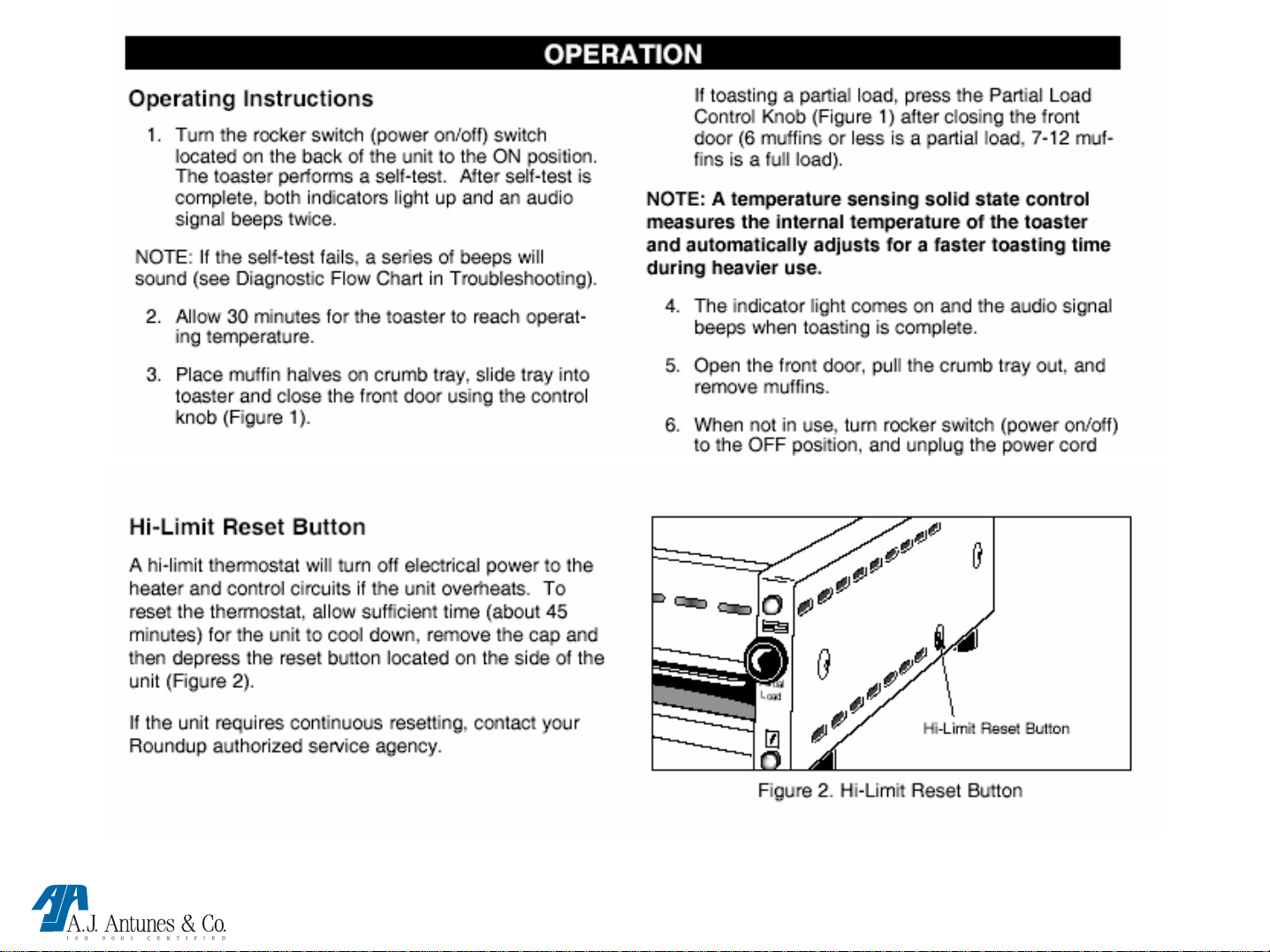
If the heating circuit continues to call for heat and the toast chamber overheats, a manual resettable
Hi-Limit Thermostat will trip and open the heating circuit. If the Hi-Limit requires repeated
resetting, the root cause must be determined.
COMPONENT DESCRIPTION & FUNCTION:
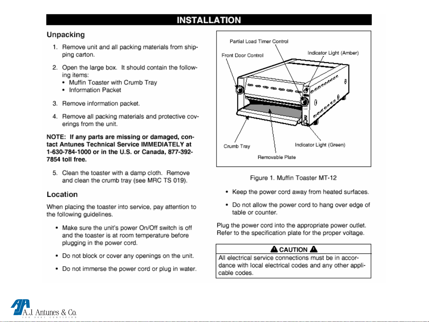
Power Switch: Turns main power On or Off to the unit’s circuitry.
Blower motor : Helps cool the exterior top, side panels, & electrical compartment by circulating
ambient air through louvers.
Transformer: Steps down the incoming supply voltage to operate the control board.
Control Board: Operates & controls all timing, signaling, diagnostic, & heating functions.
Heater Assembly: Consisting of left & right side coil, it generates the radiant heat to toast the
roduct.
Hi-Limit: Breaks & opens the heating circuit if the toast chamber overheats.
Double Pole Single Throw (DPST) Relay: When both of its input coils (+ - +-) are powered by
VDC from the control board, it closes terminals Al to A2 & B1 to B2 which allow VAC to flow to
the heater assembly.
NOTE: The VAC will fluctuate between 0-50 VAC during standby mode & 140-200 VAC during
toast mode.
Thermocouple: Monitors the toast chamber temperature and relays it to the control board. The
control board will then adjust the toast time accordingly.
MT-12 TECHNICAL MANUAL
LAST UPDATE 2-15-05
1060004 2/05
Page 10

THEORY CONTINUED
Door Micro Switch: When closed, it signals the control board to initiate a toast cycle.
NOTE: The unit will initiate a full load cycle if the amber light is off . It will initiate a partial load
cycle if the amber light is lit.
Partial Load Switch: When closed, it signals the control board that a partial load cycle has been
chosen. It will also turn on the amber light.
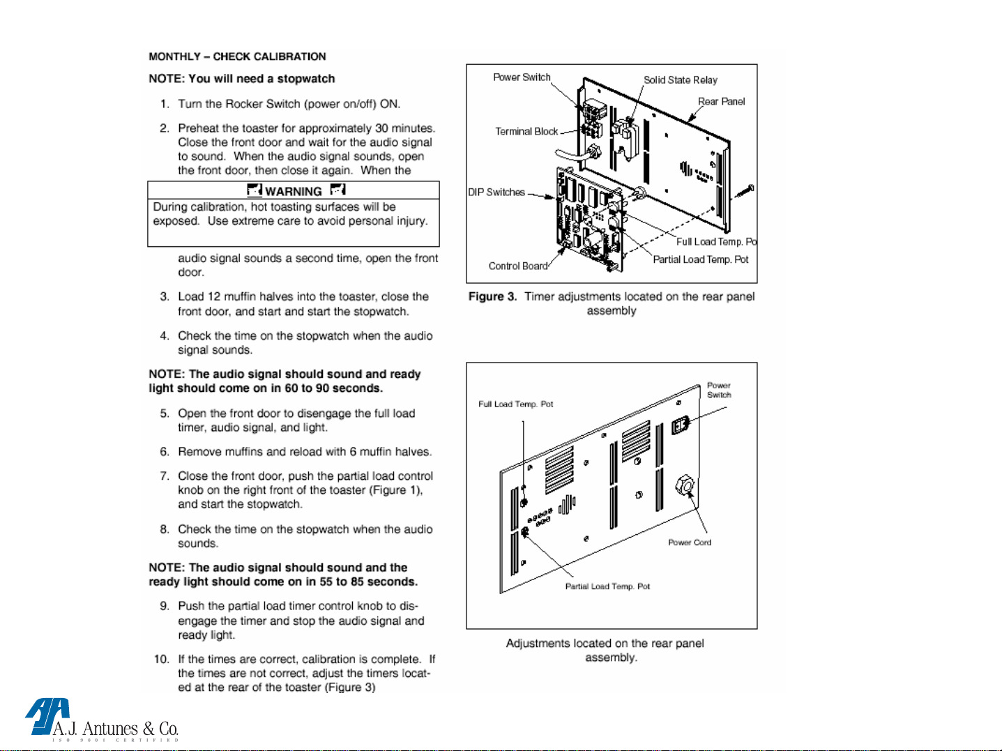
Full & Partial Load Timers (Pots): Located on the control board and accessible from the
exterior rear. When rotated clockwise (CW), it extends the toast time. If rotated counter clockwise
(CCW), it decreases the toast time. These Pots have built in stops and are initially set to 12:00
o’clock at the factory. They are adjustable from 7:00 to 5:00 o’clock.
NOTE: turning them beyond their stops will permanently damage them.
Green “ready” light: Will be lit whenever the unit is in a toast cycle (full or partial). The light will blink
at the completion of a toast cycle until the door is opened.
Amber light: Will be lit to indicate that the unit is in a partial load.
Note: The unit will start a partial load toast cycle only if the amber light is lit and the door is closed.
Toast chamber: Compartment where the product is placed for toasting.
MT-12 TECHNICAL MANUAL
LAST UPDATE 2-15-05
1060004 2/05
Page 11
MT-12 TECHNICAL MANUAL
LAST UPDATE 2-15-05
1060004 2/05
Page 12
MAINTENANCE
MT-12 TECHNICAL MANUAL
LAST UPDATE 2-15-05
1060004 2/05
Page 13
MAINTENANCE CONTINUED
MT-12 TECHNICAL MANUAL
LAST UPDATE 2-15-05
1060004 2/05
Page 14

MT-12 TECHNICAL MANUAL
LAST UPDATE 2-15-05
1060004 2/05
Page 15

TROUBLESHOOTING
Dip Switch Settings
Check your Control Board assembly to ensure the dip Switch settings are correct.
All models to be “200” and “low” (as shown below).
EXCEPT MT-12 Hi with mfg #’s 9200126/126T/127/127T/138. (THESE SHOULD BE 220 & LOW).
MT-12 TECHNICAL MANUAL
LAST UPDATE 2-15-05
1060004 2/05
Page 16

TROUBLE SHOOTING
PROBLEM: POSSIBLE CAUSE: RESOLUTION:
MUFFINS TOO LIGHT The removable muffin plate’s surface is too shiny. Verify the plate surface has a
dull finish to it. Use both sides
of plate.
Toasting refrigerated or frozen muffins. Muffins must be at room
temperature before Toasting.
Control board dip switch settings are set incorrect. Verify both dip switches are set
to “low” & “200” for all except
MT-12Hi with MFG #’s
9200126/126T/127/127T/138 220 &
low.
Toast times are too short due to full & or partial
load timers (pots) set too low. Rotate timers clockwise (CW)
but do not rotate past the built in
stops. Check your toast times
afterward Per MRC card.
Relay is dropping out during toast cycle Verify heater assembly is pulling
15.5 – 17 amps throughout the
entire toast cycle. Replace relay if
amperage is lost for any amount of
time during toast cycle.
MT-12 TECHNICAL MANUAL
LAST UPDATE 2-15-05
1060004 2/05
Page 17

TROUBLE SHOOTING
PROBLEM: POSSIBLE CAUSE: RESOLUTION:
MUFFINS TOO LIGHT
(CONTINUED)
MUFFINS BURN
ON UNDERSIDE
Heater assembly has burnt/open coil(s), Check heater coils for proper ohms
high ohms, or an incorrect voltage heater (See Parts Testing & Replacement Section).
assembly was installed. Replace if fails test.
Thermocouple has high ohms. Check thermocouple for proper ohms.
(See Parts Testing & Replacement Section).
Replace if fails test.
Faulty Control Board If the above items check out O.K, & the
toasting times are still too short or do not
adjust, replace the control board.
(See Parts Testing & Replacement Section).
The removable plate has carbon buildup Clean plate per MRC card and verify the
plates surface has a dull finish to it on both
sides.
The removable plate is not being reversed Alternate between both sides of the plate
MT-12 TECHNICAL MANUAL
LAST UPDATE 2-15-05
1060004 2/05
Page 18

TROUBLE SHOOTING
PROBLEM:
MUFFINS BURN (TOO DARK)
POSSIBLE CAUSE:
Toast times are too long due to full &
or partial timers set too high
Control board dip switch settings are
not correct
The removable plate has carbon
buildup
The removable plate is not being
reversed
Thermocouple has low ohms, or was
miswired, or was installed improperly
RESOLUTION:
Rotate timers counter clockwise (CCW)
but do not rotate past the built in
stops. Check your toast times
afterward per the MRC card.
Verify both dip switches are set to
“low” & “200” for all except MT-12 HI
with MFG #’s
9200126/126T/127/127T/138 “LOW &
220”
Clean plate per MRC card and verify
the plate’s surface has a dull finish to it
on both sides.
Alternate between both sides of the
plate
Check thermocouple for proper ohms,
wiring, & installation. (see parts testing
& replacement section & wiring
diagram).
Faulty control board If the above items check out o.k., & the
toasting times are still too long or do
not adjust, replace the control board.
(see parts testing & replacement
section).
MT-12 TECHNICAL MANUAL
LAST UPDATE 2-15-05
1060004 2/05
Page 19

TROUBLE SHOOTING
PROBLEM: POSSIBLE CAUSE
Only half of the heater assembly
works (Left coil or Right coil).
A partial section of the heater
assembly remains lit continuously
even during standby mode.
Heater assembly is on
continuously (FULLY BRIGHT)
even during standby mode.
Heater assembly has a burnt /
open coil
Heater assembly coil(s) is
grounded
SS relay terminals A1 to A2 & B1 to
B2 are stuck in the closed position
Control board is continuously
calling for full heat
:
RESOLUTION:
Check heater coils for proper
ohms.
(see parts testing & replacement
section).
Check heater coils for grounds &
proper ohms.
(see parts testing & replacement
section).
Disconnect the red pin connector
from the relay. Clamp an amprobe
onto the black wire on terminal A2,
is there any amp draw? If yes,
replace relay.
(see parts testing & replacement
section).
Disconnect the red pin connector
from the relay. Does the heater
assembly go dim? If so, replace
control board.
MT-12 TECHNICAL MANUAL
LAST UPDATE 2-15-05
(see parts testing & replacement
section).
1060004 2/05
Page 20

TROUBLE SHOOTING
PROBLEM: POSSIBLE CAUSE: RESOLUTION:
No heat & power switch Circuit breaker off or tripped. Reset & check receptacle for line VAC.
Light is off Open line in power cord/terminal
block. Check power cord/ terminal block for
continuity. Replace damaged terminals or
wires
(see parts testing and replacement section).
Open power switch. Check switch for continuity.
(see parts testing and replacement section).
Power Switch light is on Hi-limit is tripped. Push to reset, If starts to heat, See “Hi-limit
but no heat trips” section in this manual..
Hi-limit is open and does not reset. Check Hi-limit for continuity.
(see parts testing & replacement section).
Inoperable step down transformer With unit powered on verify line voltage
across terminals 1 & 5, If present, check
for 10 to 12 VAC across terminals 6 & 7
and 6 to 8 VAC across terminals 9 & 10.
If voltage not present across terminals 6 & 7
and 9 & 10 replace transformer.
(see parts testing and replacement section).
DPST relay is not closing. Close front door to simulate a toast cycle. Is
(DOUBLE POLE SINGLE THROW) 3.5 to 7.0 VDC present at red relay connector
wires blue (-), red (+) ? If yes, is line voltage
present across A1 & B1 ? If yes, is 140 to 200
VAC present across A2 & B2? If not, replace
relay. (see parts testing & replacement section).
MT-12 TECHNICAL MANUAL
LAST UPDATE 2-15-05
1060004 2/05
Page 21

TROUBLE SHOOTING
PROBLEM: POSSIBLE CAUSE: RESOLUTION
Power switch light is on but Heater coils / circuit is open Disconnect unit from power source. Remove
no heat (continued). black and white wires from relay terminals A2 &
B2. check for 11 to 14 Ohms. If high Ohms or
“infinity”, check for burnt or damaged wires.
If wires burnt or damaged, replace wires.
If wires are ok, replace heater assembly.
(see parts testing & replacement section).
Faulty control board Verify all wiring, terminals, connectors are
properly secured on all components. Power
unit on & close front door to simulate a toast
cycle. Locate white plastic connector (P1) on
control board. Is 10 – 12 VAC present across
the 2 black wires & 6 to 8 VAC present across
the 2 brown wires ? If yes but there is no rear
Led function, & or 3.5 to 7.0 VDC to the relay’s
(red plastic connector) Blue (-), red (+), replace
control board. (see parts testing & replacement
section).
:
Loose burnt, broken wiring in Check heating circuit wiring for continuity &
heating circuit. replace any damaged wires or terminals. Use
wiring diagram for reference.
Faulty thermocouple (unit Check thermocouple for proper ohms.
repeatedly beeps 5 times & pauses) (see parts testing & replacement section).
The relay’s red plastic connector is Verify that the connector’s red wires align with
not attached properly. the (+) pins, and the blue properly wires align
with the (-) pins of the relay. See wiring diagram
Faulty Board to Relay wiring Check harness for continuity.
harness
MT-12 TECHNICAL MANUAL
LAST UPDATE 2-15-05
1060004 2/05
Page 22

TROUBLE SHOOTING
PROBLEM:
HI-LIMIT TRIPPING Toast chamber is overheating due to
the SS Relay terminals A1 to A2 & B1 to
B2 stuck closed
Hi-Limit is tripping prematurely (Unit
toasts fine prior to tripping the hi-limit)
Faulty Control Board Are the heater coils still fully bright at the
RESOLUTION:POSSIBLE CAUSE:
Disconnect the red pin connector from the
relay. Clamp an amprobe onto the black
wire on terminal A2. Is there any amp
draw? If yes, replace relay
(SEE PARTS TESTING & REPLACEMENT
SECTION).
Are the heater coils fully bright during a
toast cycle? If yes, do they go dim at the
completion of the cycle? If yes, replace
the hi-limit
(SEE PARTS TESTING & REPLACEMENT
SECTION).
completion of a toast cycle? During
standby? If yes, disconnect the relay’s red
pin connector. Do the coils turn off?
If yes Replace the control board.
MT-12 TECHNICAL MANUAL
LAST UPDATE 2-15-05
(SEE PARTS TESTING & REPLACEMENT
SECTION).
1060004 2/05
Page 23

POT ADJUSTMENT
Pot settings, LED’S, Audio
Both full & partial load settings (above) are set
to 12 o’clock
MT-12 TECHNICAL MANUAL
1060004 2/05
LAST UPDATE 2-15-05
Page 24

1 2 3 4
5 6 7
LED DISPLAY
Operationl / Diagnostic LED’S : Seven (7) Red Led’s are incorporated on the control board.
Use chart below for reference.
Led 1: When lit, it indicates that the full load switch is closed & the unit is in a toast cycle
(Full Load or Partial Load).
NOTE: The green “ready” light will also be on.
Led 2: When lit, it indicates that the thermocouple is disconnected or open.
NOTE: Unit will not call for heat. This Led should not be lit in normal operation.
LED LAYOUT
NOTE: THE AMBER LIGHT IS FOR PARTIAL LOAD AND IS ACTIVATED WHEN THE KNOB IS PUSHED OR
DEACTIVIATED WHEN THE KNOB IS PUSHED AGAIN.
Led 3: When lit, it indicates the control board is calling for heat by supplying .5-1.5 VDC (During
Standby Mode) or 3.5-7.0 VDC (During Toast Mode) to the SS relay input terminals (+ - + -).
NOTE: The VDC will pulse along with the led.
Led 4: When lit, it indicates that 2-3 VDC is being supplied to the green “ready” light.
NOTE: The green light should be on.
Led 5: When lit, it indicates that the partial load switch is closed.
NOTE: The amber light should be on.
Led 6: When lit, it indicates that 10 VDC is being supplied to the audio signal.
NOTE: The audio signal should beep during this time.
Led 7: When lit, it indicates that 4-5 VDC is being supplied to the amber light.
NOTE: The amber light should be on.
MT-12 TECHNICAL MANUAL
LAST UPDATE 2-15-05
1060004 2/05
Page 25

AUDIO / BEEP CODES
DIAGNOSTIC BEEP CODES:
Four (4) diagnostic beep codes are incorporated in this control board. They indicate the following.
2 beeps followed by a 2 second pause until unit is turned off: Indicates supply input voltage is
below 180 VAC.
3 beeps followed by a 2 second pause until the unit is turned off: Indicates toast chamber
temperature is above 750 F (400 C) after 30 minutes.
4 beeps followed by a 2 second pause until the unit is turned off: Indicates toast chamber
temperature is below 150 F (65 C) after 30 minutes.
5 beeps followed by a 2 second pause until the unit is turned off: Indicates the thermocouple is
disconnected, open, or has high ohms.
NOTE: Unit will not call for heat.
MT-12 TECHNICAL MANUAL
LAST UPDATE 2-15-05
1060004 2/05
Page 26

PARTS TESTING AND
REPLACEMENT
PROCEDURES
MT-12 TECHNICAL MANUAL
LAST UPDATE 2-15-05
1060004 2/05
Page 27

PARTIAL KNOB / LEVER ADJUSTMENT, OR SWITCH
REPLACEMENT
Partial rod
Lock nuts
5. Install new Switch, loosen both lock nuts and adjust so t hat there
is zero space between the Switch and Partial Rod
6. Tighten lock nuts.
TESTING PROCEDURE:
Disconnect wires to isolate partial load switch. Check terminals for continuity &
infinity.
Replace if reads continuous continuity or infinity, even after fully
depressing switch.
MT-12 TECHNICAL MANUAL
LAST UPDATE 2-15-05
. (as shown)
1060004 2/05
Page 28

REPLACING THE HEATER ELEMENT
REMOVE:
• Remove the side panels.
• Remove front panel.
• Remove the wires from heater terminals and push thru
the hole in the side panel.
• Remove the (3) heater retainer screws & then remove
the retainer.
• Remove heater assembly and repl ace with new.
REPLACE:
• Replace heater retainer & screws.
41 2 3
• Re-insert wires thru hole in side panel.
• Reconnect wires to element ends per diagram.
• Replace front panel
• Replace side panels.
MT-12 TECHNICAL MANUAL
LAST UPDATE 2-15-05
TESTING PROCEDURE:
Disconnect wires to isolate both left & right side heater coils.
200 volt heaters: Terminals 1 & 2, 3 & 4 to be (21.5 – 22.5 cold ohms).
220 volt heaters: Terminals 1 & 2, 3 & 4 to be (26 – 27.5 cold ohms).
Replace if either coil measures high ohms or infinity, or if either
terminal shows a reading to (chassis) ground. Using the highest ohm
scale.
NOTE: If coils are measured in parallel, 11 – 14 ohms will be
measured.
1060004 2/05
Page 29

REPLACING THE RELAY
•
Turn toaster off and let cool.
• Remove rear panel.
• Remove wires from relay. (mark for re-installation)
• Remove 2 screws.
• Remove relay.
• Replace with new relay
• Replace 2 screws.
• Replace wires. (use diagram if needed).
• Turn toaster on and verify working correctly.
A1 B1
A2 B2
• Red plastic connector Red wires are (+), Blue wires
are (-).
TESTING PROCEDURE:
Relay must be tested while powered up (see theory of operation).
Replace if fails test
MT-12 TECHNICAL MANUAL
LAST UPDATE 2-15-05
Red connector
1060004 2/05
Page 30

REPLACING THE THERMOCOUPLE
MT-12 TECHNICAL MANUAL
LAST UPDATE 2-15-05
INSIDE THE TOAST CHAMBER AT
THE REAR UPPER RIGHT CORNER.
THE THERMOCOUPLE PROJECTS
APPROXIMATELY ¼ “ INTO THE
TOAST CHAMBER..
TESTING PROCEDURE:
Disconnect wires to isolate Thermocouple.
Check for 2 to 3 ohms at room temperature.
Replace if measures high ohms or
infinity.
1060004 2/05
Page 31

REPLACING THE HI-LIMIT
•
Turn toaster off and let cool.
•
Remove side panel.
• Remove retainer ring (shown below).
• Remove manilla insulator card (shown below).
• Remove 2 brass screws holding wires.
• Remove 2 screws from cabinet Holding Hi-limit.
• Remove Hi-limit and replace using the 2 screws.
• Re-attach wires with 2 brass screws.
• Re-attach manilla card.
• Re-attach retainer ring.
• Turn toaster on and verify working correctly.
• Re-attach side panel.
MT-12 TECHNICAL MANUAL
LAST UPDATE 2-15-05
2 Brass screws
holding wires
i
m
-
i
i
l
H
g
n
i
d
l
o
h
s
w
e
r
c
s
2
TESTING PROCEDURE:
Fully press & release the reset button. Disconnect wires to isolate
hi-limit. Check terminals for continuity.
Replace if measures high ohms or infinity.
1060004 2/05
t
Page 32

REPLACING THE BOARD
• Turn toaster off and let cool.
• Remove rear panel.
• Remove 4 screws & nuts holding board.
• Remove wires.
• Replace with new board.
• Replace 4 screws & nuts.
• Replace wires.
• Set dip switches accordingly.
• Replace rear panel.
• Turn unit on and test.
TESTING PROCEDURE:
The control board must be tested While powered up
(see theory of operation).
Replace if fails test
MT-12 TECHNICAL MANUAL
LAST UPDATE 2-15-05
NOTE: Screws and nuts (on all 4 corners) 4 total
1060004 2/05
Page 33

REPLACING THE TRANSFORMER
Remove back panel.
Remove wires (mark them accordingly).
Remove 2 mounting screws.
Move wires to new transformer one at a time.
Re-install screws holding transformer.
TESTING PROCEDURE:
Disconnect wires to isolate transformer.
Terminals 1 & 5 (115 ohms).
Terminals 6 & 7 (0.33 Ohms).
Terminals 9 & 10 (1.83 ohms).
All readings +/- 10 %.
Replace if any coils measure high ohms or infinity.
6
6
5
7
9
1
10
MT-12 TECHNICAL MANUAL
LAST UPDATE 2-15-05
1060004 2/05
Page 34

REPLACING THE BLOWER MOTOR
• Remove 2 upper & 2 lower nuts from blower
assembly mounting plate.
• Remove blower assembly.
• Move wires to new blower assembly, one wire at
a time.
• Install new blower assembly and tighten nuts
firmly.
TESTING PROCEDURE:
Disconnect wires to isolate motor.
Check motor for 59 ohms +/- 10%.
Replace if measures high ohms or infinity.
MT-12 TECHNICAL MANUAL
LAST UPDATE 2-15-05
1060004 2/05
Page 35

REPLACING ROCKER SWITCH
• 1. Squeeze tabs on sides of Rocker Switch and
push Switch out of Rear Panel.
• 2. Move wires to new Switch, one wire at a time.
• 3. Push new Switch into Rear Panel.
• 4. Discard old Switch.
WARNING
• Toaster should be allowed to cool before performing
any maintenance
TESTING PROCEDURE:
Disconnect wires to isolate power switch.
Turn switch to the “on” position and check terminals 1 & 2, then 4 & 5 for continuity.
Replace if measures high ohms or infinity.
MT-12 TECHNICAL MANUAL
LAST UPDATE 2-15-05
1060004 2/05
Page 36

MICRO SWITCH
TESTING PROCEDURE:
Disconnect wires to isolate micro switch.
With the lever relaxed, check terminals C & N/C for continuity.
If so, manually depress & hold lever.
Reading should now be infinity.
Replace if fails either test.
MT-12 TECHNICAL MANUAL
LAST UPDATE 2-15-05
1060004 2/05
Page 37

POWER CORD / TERMINAL BLOCK
TESTING PROCEDURE:
Disconnect wires at terminal block to isolate power cord.
Verify continuity from each plug prong to the corresponding wire at the end of the power cord.
Check terminal block for continuity.
Repair or replace if fails test.
MT-12 TECHNICAL MANUAL
LAST UPDATE 2-15-05
1060004 2/05
Page 38

LIGHT REPLACEMENT
TESTING PROCEDURES:
Amber light (TOP):
Disconnect wires to isolate “Amber” partial load light.
Set a VOM on the “diode check” setting.
Verify reading 1.0 to 2.0.
Replace if fails test.
Green light (BOTTOM):
Disconnect wires to isolate “Green” ready light.
Set a VOM on the “diode check” setting.
Verify reading 1.0 to 2.0.
Replace if fails test.
LIGHT REPLACEMENT:
•Remove the right side panel.
• Remove wires from light (as shown).
• Squeeze the tabs on light together and push light thru hole.
• Insert replacement light thru hole until tabs click.
• Re-attach the 2 wires.
NOTE: WHITE WIRES MUST BE ATTACHED TO TERMINAL
WITH A RED DOT (AS SHOWN ABOVE).
MT-12 TECHNICAL MANUAL
LAST UPDATE 2-15-05
1060004 2/05
Page 39

MT-12’S BUILT WITH DOUBLE POLE RELAYS
WITH MFG #’S
9200121/123/125/127/127T/129/130/131/132/134/
136/138/140/142/144
P1
EARLY MT-12’S BUILT WITH SINGLE POLE RELAYS
MFG #’S 9200120/122/124/126/126T/128
MT-12 TECHNICAL MANUAL
LAST UPDATE 2-15-05
1060004 2/05
Page 40

MT-12 TECHNICAL MANUAL
LAST UPDATE 2-15-05
1060004 2/05
Page 41

Tools required.
• Volt Ohm Meter (VOM). (Digital or Analog).
• Flat blade screwdriver ¼ “.
• Phillips head screwdriver.
• Needle nose pliers.
• Nut driver set
• Amprobe (Digital or Analog).
MT-12 TECHNICAL MANUAL
LAST UPDATE 2-15-05
1060004 2/05
 Loading...