

Page 1

180 Kehoe Blvd.
Carol Stream, Illinois 60188 USA
1-877-392-7854 (Tech Service).
MS TECHNICAL MANUAL
LAST UPDATE 12-10-04
1060003 12/04
Page 2
MS
STEAMER
TRAINING
MS TECHNICAL MANUAL
LAST UPDATE 12-10-04
1060003 12/04
Page 3

MS
•Warranty
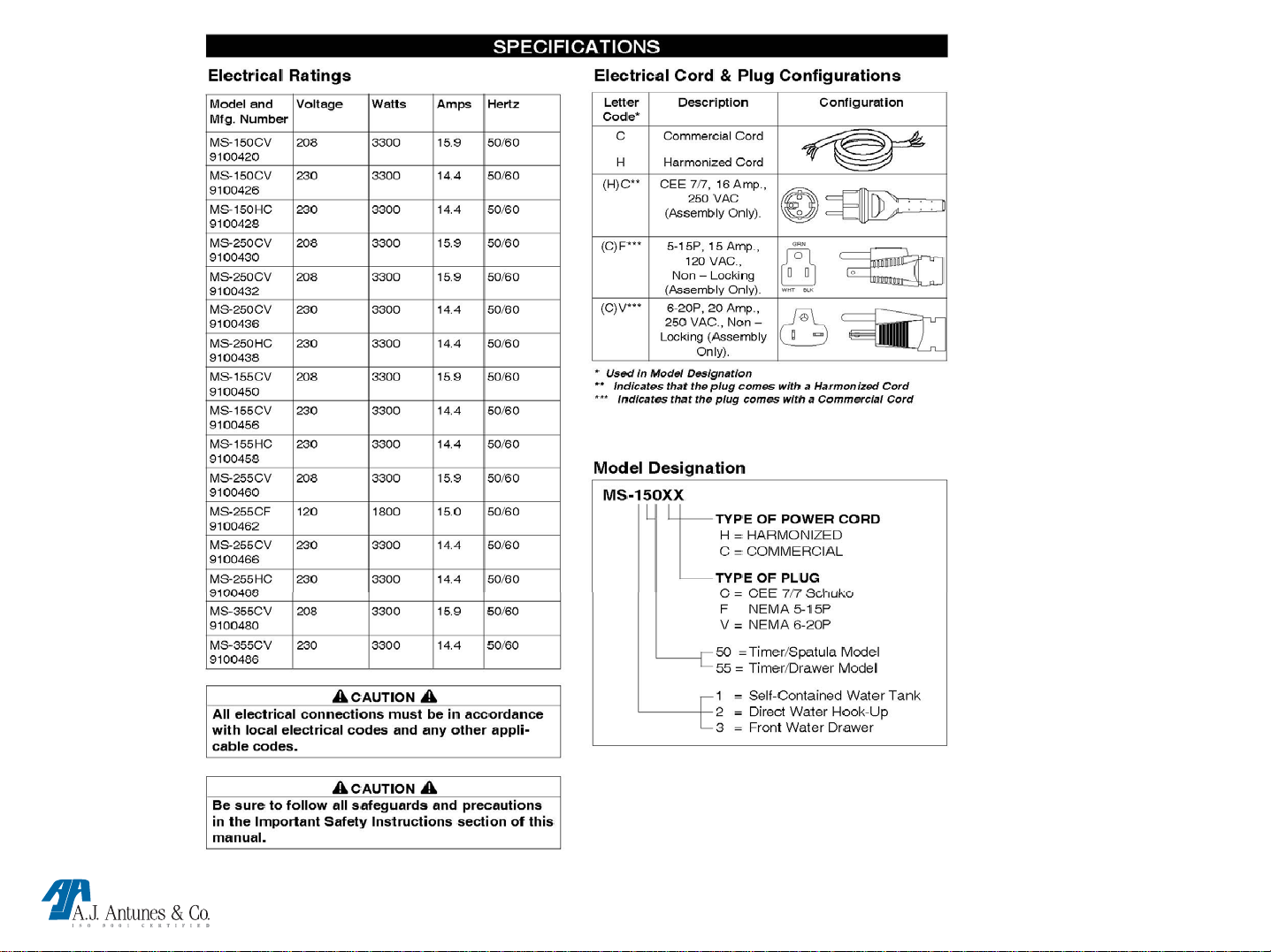
•Specifications
•Steamer warnings
•Steamer installation
•Operating instructions
•Technical Theory of Operation
•Component description & functions
•Tools Required
•Steamer Maintenance
•Troubleshooting
•Parts testing & replacement
•Type “k” Millivolt chart
•Wiring diagram
MS TECHNICAL MANUAL
LAST UPDATE 12-10-04
1060003 12/04
Page 4

LIMITED WARRANTY
Equipment manufactured by Roundup Food Equipment Division of A.J. Antunes & Co. has been
constructed of the finest materials available and manufactured to high quality standards. These units are
warranted to be free from mechanical and electrical defects for a period of one year from date of purchase
or 18 months from shipment from factory, whichever occurs first, under normal use and service, and when
installed in accordance with manufacturer’s recommendations. To insure continued proper operation of
the units, follow the maintenance procedure outlined in t he Owner’s Manual.
1. This warranty does not cover cost of installation, defects caused by improper storage or handling prior to
placing of the Equipment. This warranty does not include overtime charges or work done by unauthorized
service agencies or personnel. This warranty does not cover normal maintenance, calibration, or regular
adjustments as specified in operating and maintenance instructions of this manual, and/or labor involved
in moving adjacent objects to g ai n access t o the Equipment. This w arranty does no t cover consumabl e
items such as the Platen, Release Sheets, Conveyor Belt Wraps, gaskets, O-rings, light bulbs, nor does it
cover water contaminant problems such as foreign material in water lines or inside solenoid valves. It does
not cover water pressure problems or failures resulting from improper/incorrect voltage supply. This
warranty does not pay travel, mileage, or any other charges for an Authorized Service Agency to reach the
equipment location.
2. Roundup reserves the right to make changes in design or add any improvements on any product. The right
is always reserved to modify equipment because of factors beyond our control and government
regulations. Changes to update equipment do not constitute a warranty charge.
3. If shipment is damaged in transit, the purchaser should make a claim directly upon the carrier. Careful
inspection should be made of the shipment as soon as it arrives and visible damage should be noted upon
the carrier’s receipt. Damage should be reported to the carrier. This damage is not covered under this
warranty.
4. Warranty charges do not include freight or foreign, excise, municipal or other sales or use taxes. All such
freight and taxes are the responsibility of the purchaser.
5. THIS WARRANTY IS EXCLUSIVE AND IS IN LIEU OF ALL OTHER WARRANTIES, EXPRESSED OR IMP LIED,
INCLUDING ANY IMPLIED WARRANTY OR MERCHANTABILITY OR FITNESS FOR A PARTICULAR
PURPOSE, EACH OF WHICH IS HEREBY EXPRESSLY DISCLAIMED. THE REMEDIES DESCRIBED ABOVE
ARE EXCLUSIVE AND IN NO EVENT SHALL ROUNDUP BE LIABLE FOR SPECIAL CONSEQUENTIAL OR
INCIDENTAL DAMAGES FOR THE BREACH OR DELAY IN PERFORMANCE OF THIS WARRANTY.
MS TECHNICAL MANUAL
LAST UPDATE 12-10-04
1060003 12/04
Page 5
MS TECHNICAL MANUAL
LAST UPDATE 12-10-04
1060003 12/04
Page 6
MS TECHNICAL MANUAL
LAST UPDATE 12-10-04
1060003 12/04
Page 7

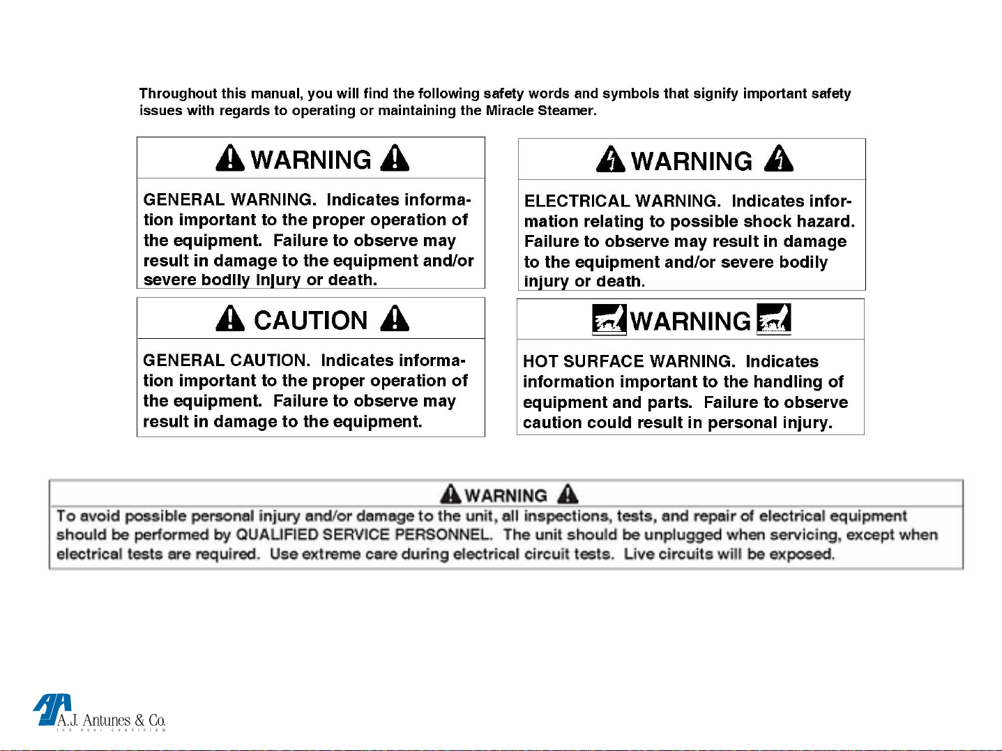
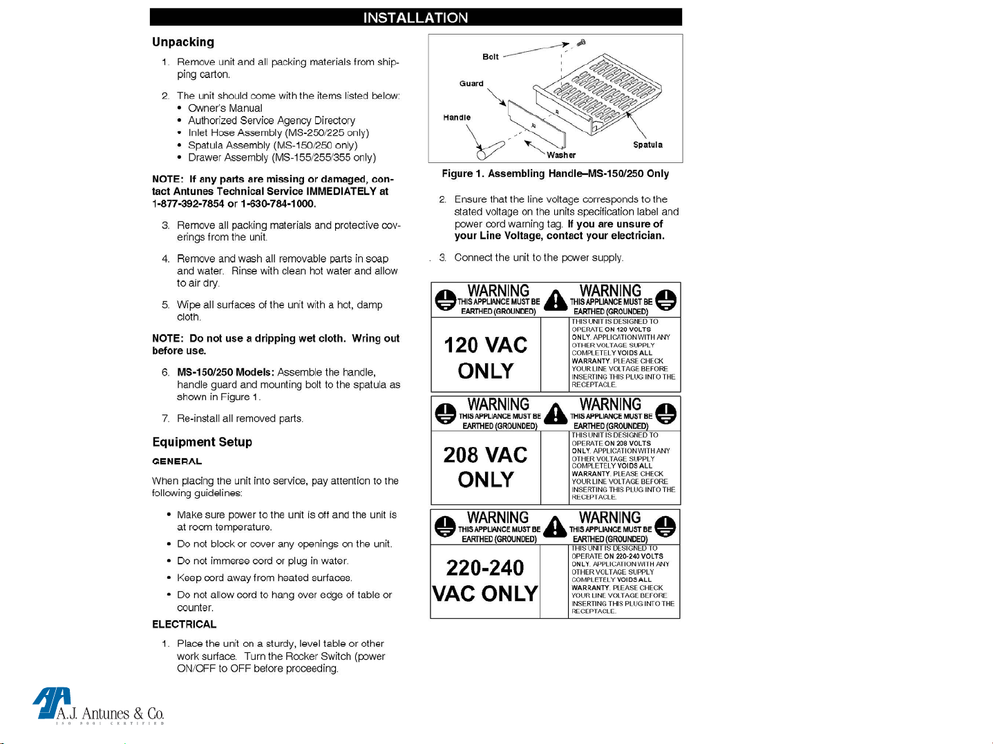
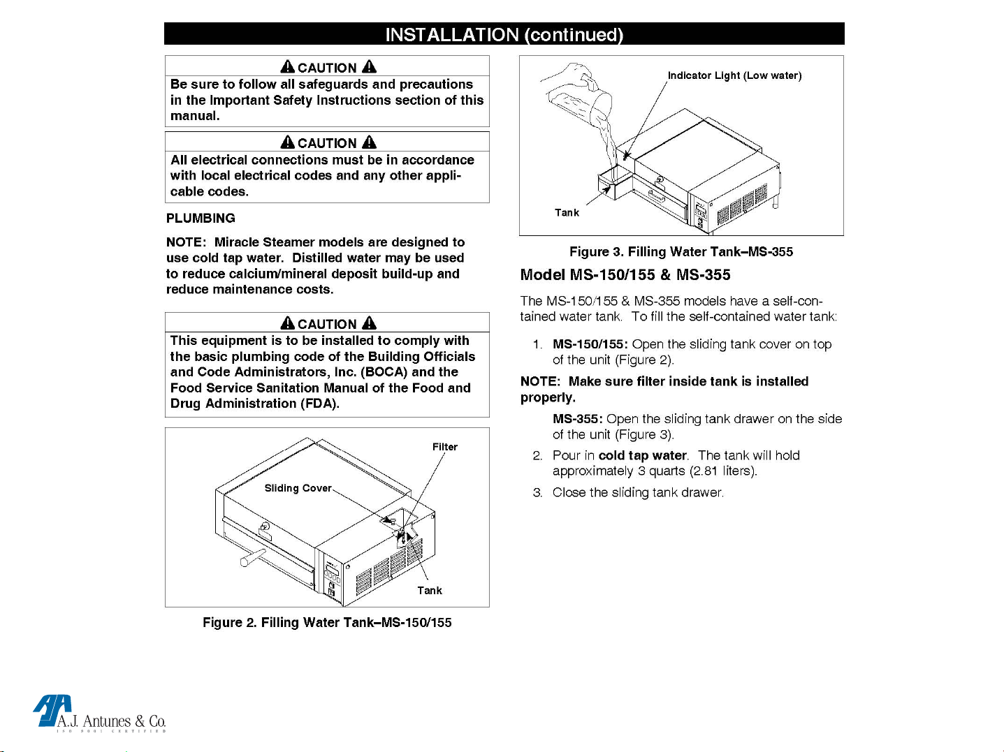
In addition to the warnings and cautions in this manual, use the following guidelines for safe operation of
the unit.
• Read all instructions before using equipment.
• For your safety, the equipment is furnished with a properly grounded cord connector.
Do not attempt to defeat the grounded connector.
• Install or locate the equipment only for its intend- ed use as described in this manual.
Do not use corrosive chemicals in this equipment.
• Do not operate this equipment if it has a dam- aged cord or plug, if it is not working properly, or if it has
been damaged or dropped.
• This equipment should be serviced by qualified personnel only. Contact the nearest Roundup authorized service
facility for adjustment or repair.
• Do not block or cover any openings on the unit.
• Do not immerse cord or plug in water.
• Keep cord away from heated surfaces.
• Do not allow cord to hang over edge of table or counter.
The following warnings and cautions appear throughout this manual and should be carefully observed.
• Turn the unit off, disconnect the power source and allow unit to cool down before performing any service or
maintenance on the unit.
• The equipment should be grounded according to local electrical codes to prevent the possibility of electrical
shock. It requires a grounded receptacle with separate electrical lines, protected by fuses or circuit breaker of the
proper rating.
• All electrical connections must be in accordance with local electrical codes and any other applicable codes.
• WARNING ELECTRICAL SHOCK HAZARD. FAILURE TO FOLLOW THESE INSTRUCTIONS COULD
RESULT IN SERIOUS INJURY OR DEATH.
Electrical ground is required on this appliance.
Do not modify the power supply cord plug. If it does not fit the outlet, have a proper outlet installed by a
qualified electrician.
• Do not use an extension cord with this appliance.
MS TECHNICAL MANUAL
LAST UPDATE 12-10-04
1060003 12/04
Page 8

• Check with a qualified electrician if you are in doubt as to whether the appliance is properly grounded.
• This equipment is to be installed to comply with the basic plumbing code of the Building Officials and Code
Administrators, Inc. (BOCA) and the Food Service Sanitation Manual of the Food and Drug Administration
(FDA).
• If the supply cord is damaged, it must be replaced by the manufacturer or its service agent, or a similarly qualified
person.
• Do not clean this appliance with a water jet.
• Do not use a sanitizing solution or abrasive materials. The use of these may cause damage to the stainless steel
finish.
• To ensure proper steaming characteristics, some calcium/mineral deposits must be present on the generator
surface. If, during cleaning, the surface does become free of calcium / mineral deposits, one approved method is to
add plain tap water to the surface and allow it to boil off. This will ensure proper steaming characteristics by creating
a thin layer of deposits on the surface.
• Chlorides or phosphates in cleansing agents
(such as bleach, sanitizers, degreasers or detergents) could cause permanent damage to stainless steel equipment..
The damage is usually in the form of discoloration, dulling of metal surface finish, pits, voids, holes or cracks. This
damage is permanent and not covered by warranty.
• The following tips are recommended for maintenance of your stainless steel equipment,
• Always use a soft, damp cloth for cleaning, rinse with clear water and wipe dry. When required, always rub in
direction of metal polish lines.
• Routine cleaning should be done daily using soap, ammonia detergent and water.
• Stains and spots should be sponged using a vinegar solution as required.
• Finger marks and smears should be rubbed off using soap and water.
• Hard water spots should be sponged using a vinegar solution.
MS TECHNICAL MANUAL
LAST UPDATE 12-10-04
1060003 12/04
Page 9
MS TECHNICAL MANUAL
LAST UPDATE 12-10-04
1060003 12/04
Page 10
MS TECHNICAL MANUAL
LAST UPDATE 12-10-04
1060003 12/04
Page 11
MS TECHNICAL MANUAL
LAST UPDATE 12-10-04
1060003 12/04
Page 12
MS TECHNICAL MANUAL
LAST UPDATE 12-10-04
1060003 12/04
Page 13
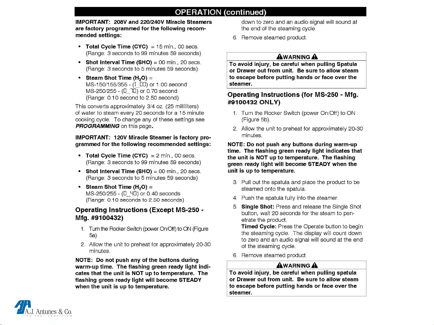
Operation continued
MS TECHNICAL MANUAL
LAST UPDATE 12-10-04
1060003 12/04
Page 14
MS TECHNICAL MANUAL
LAST UPDATE 12-10-04
1060003 12/04
Page 15
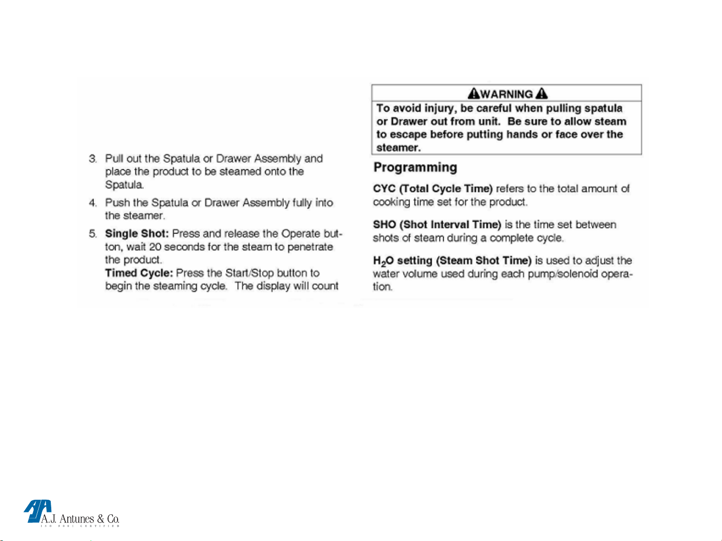
Operation continued
MS TECHNICAL MANUAL
LAST UPDATE 12-10-04
1060003 12/04
Page 16
MS TECHNICAL MANUAL
LAST UPDATE 12-10-04
1060003 12/04
Page 17
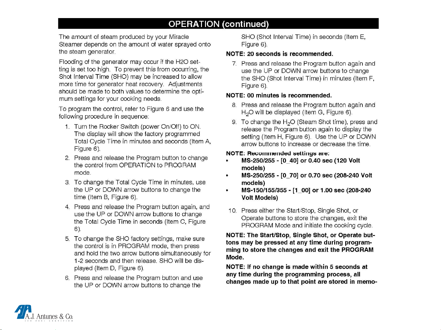
Operation continued
MS TECHNICAL MANUAL
LAST UPDATE 12-10-04
1060003 12/04
Page 18

MS TECHNICAL MANUAL
LAST UPDATE 12-10-04
1060003 12/04
Page 19

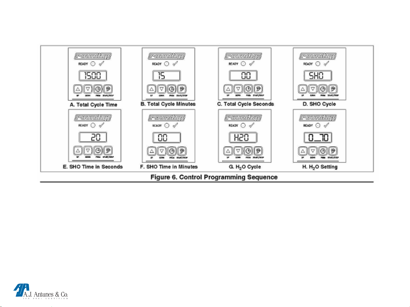
Operation continued
MS TECHNICAL MANUAL
LAST UPDATE 12-10-04
1060003 12/04
Page 20

MS
TECHNICAL THEORY OF OPERATION
When the power switch is on, line voltage flows to the primary side of the step down transformer. The transformer’s
secondary side supplies 12 & 24 VAC to the control board. Once power ed, & provided that the generator temperature
is below 380 F (193 C), the control board calls for heat by supplying 10-15 VDC to the solid state relay terminals 3 (+) 4
(-). Once powered, the relay closes terminals 1 & 2, which allows line voltage to flow to the generator. As the generator
begins to heat up, a type “K” thermocouple monitors the internal generator temperature. As the heat continues to
increase, so does the thermocouple’s DC millivolts. Once the generator’s temperature rises to 380-420 F (193-215 C),
the thermocouple is generating approximately 7.5-9.0 DC millivolts. The control board receives these millivolts &
proceeds to remove the 10-15 VDC to the solid state relay since the heating circuit has now become satisfied. Then,
relay terminals 1 & 2 open up, and the generator stops heating. The heating circuit will cycle on & off as needed, even at
idle. When the squared momentary button or the “Single Shot”/”Start/Stop” touch pad button is pushed, it signals the
control board to supply 24 VAC to the solenoid valve used in the MS-250’s/255’s or the water pump used in MS150’s/155’s/355’s for approximately one second. The solenoid valve opens, or the water pump runs, and allows a shot of
water (Approximately ¾-1 oz 25-30 ml) to flow onto the generator surface for steaming.
NOTE: If the display is in a “Timed Cycle” (Counting Down), the control board will continue to activate the
solenoid valve or water pump for repeated shots of water, once every 20 seconds, and for the duration of the
cycle time displayed. See Programming. Since the generator’s circular cover is secured in place with a wing
nut, the steam is forced downward through the generator steam ports and onto the product. The Control
Board’s parameters can be custom programmed for the overall cycle steam time (CYC), as well as the interval
time in seconds (SHO) when each shot of water occurs, and also the water volume (H2O) used per each shot of
water (See Programming). This control board incorporates several Led’s for status & diagnostic purposes. See
“Led Layout” in troubleshooting section of the technical manual. An audio signal will sound for 3 seconds at
the end of a Timed Cycle. If the heating circuit continues to call for heat and the generator overheats, a manual
resettable Hi-Limit Thermostat will trip and open the generator circuit.
NOTE: If this condition should repeat, the root cause must be determined & corrected.
MS TECHNICAL MANUAL
LAST UPDATE 12-10-04
1060003 12/04
Page 21

MS Component Description & Function
Power Switch: Double Pole Single Throw, turns the supply voltage On or Off to the unit’s internal line voltage
components. NOTE: The built in led illuminates when line voltage is present into & out of the switch. If not lit,
line voltage is not present into or out of the switch.
Squared Momentary Switch: Single Pole Single Throw, when pressed & released, it completes a low voltage
circuit to the control board. The control board then initiates a timed steam cycle.
Step down Transformer: Consisting of 2 primary coils & 1 secondary coil, it steps down the incoming supply
voltage to operate the low voltage components (control board, solenoid valve, SS relay input side, momentary switch).
NOTE: If supply voltage is 208-240, the Primary coils are wired in series. If supply voltage is 120 volts, they are
wired in parallel.
NOTE: The secondary coil has a center tap (Terminal 8) that supplies 12 VAC. The two outer taps, (Terminals 6
& 10) supply 24 VAC. NOTE: The 12 VAC operates the control board. The 24 VAC operates the solenoi d valve
used in (MS-250/255) or the water pump used in (MS-150/155).
Control Board: Operates & controls all the timing, steaming, signaling, diagnostic, & heating functions. NOTE:
This control board incorporates 4 Led’s for status & diagnostic purposes. See “Led Display” in
Troubleshooting Section.
SS Relay: A Solid State, Single Pole Single Throw relay that is located at the rear of the unit & mounted on a heat
sink. When its input coil, (Terminals 3 + & 4 - ) is supplied 10-15 VDC by the control board, it allows the line voltage
contacts (Terminals 1 & 2) to close. Once they close, line voltage is supplied to the generator. NOTE: SS relays should
not be tested/diagnosed with an ohmmeter since this test is not reliable. Testing/Diagnosing an SS relay should
be conducted with the steamer & relay powered, and the use of a voltmeter. If faulty, this relay will permanently
fail open (No heat condition) or closed (Overheating condition). They do not fail intermittently. NOTE: Terminals
3 (+) & 4 (-) are polarity sensitive. The wiring can be inadvertently switched at the control board or at the relay if
either component is ever replaced. If so, 10-15 VDC will still be present at the relay, but it will not energize.
Therefore, the generator will not heat up. Always verify per wiring diagram.
MS TECHNICAL MANUAL
LAST UPDATE 12-10-04
1060003 12/04
Page 22

MS Component Description & Function
Generator: Also known as a heating plate, it is a circular shaped aluminum casting consisting of a permanently
integrated heating element. When powered, it generates heat to convert a shot of water (approximately ¾-1oz 25-30
ml) into steam instantaneously.
NOTE: Theses generators come in 120, 208, & 230 volt versions & are voltage specific. They must operate on
the proper voltage supply, otherwise, they are prone to premature failure. NOTE: All generators are artificially
seasoned (Limed) at the factory. A mixture of water, baking soda, & lime, is poured onto the generator
surface to steam away & formulate a thin layer of calcium buildup. A thin layer is always needed for proper
steaming characteristics. See “Monthly Maintenance” section.
Generator Lid:
steam to be forced down through the generator steam ports, & onto the product.
Generator Diffuser Plate: A circular shaped plate with many small orifices. Helps contain & prevent loose particles
from being directed onto the food product.
A circular shaped, gasket less lid that is secured onto the generator with a wing nut. Allows the
Chimney: Located at the rear of the unit, it allows excessive steam in the food compartment to exit the steamer
from the rear, & also allows the condensation to drain into a drip tray below it.
Thermocouple: A type “K” consisting of 2 wires, Red (-) & Yellow (+). One end plugs into the control board &
the other is inserted into a hole in the generator. As it monitors the internal generator temperature, it generates & relays
DC millivolts to the control board (See Millivolt Chart). NOTE: At the control board, the thermocouple connector
plugs into 3 male pins. The center pin is positive (+) & MUST always align with the yellow wire. The two outer
pins are negative (-) & either one must align with the red wire.
Hi-Limit: A capillary tube style, normally closed temperature switch that monitors the internal generator temperature.
If the heating circuit fails & runs away, the hi-limit will trip (Between 550-590 F (287-310 C), & open the generator
circuit. NOTE: If the hi-limit trips, the reset button must be manually pressed to reset it. If at any time a hi-limit
trips, the root cause must be determined & corrected.
MS TECHNICAL MANUAL
LAST UPDATE 12-10-04
1060003 12/04
Page 23

MS Component Description & Function
Solenoid Valve: Used in direct water feed units the MS-250/255, it is a normally closed 24 VAC water valve that is
electrically operated for approximately one second by the control board during a steam cycle.
NOTE: The “IN” & “OUT” markings on the valve body must correspond with water flow, otherwise, the valve will
leak through. If the valve is installed correctly and leaking through, debris/speck has become lodged within the
plunger & body area. Disassembly & cleaning of the plunger area is simple. See “Parts Testing & Replacement
Procedure” section.
Water Pump: Used in water tank equipped units the MS-150/155/355, it is a 24 VAC oscillating pump that is
electrically operated for approximately 1 second by the control board during a steam cycle. It pumps water
(Approximately ¾-1 oz 25-30 ml) from the tank reservoir onto the generator surface. It consists of an internal intake &
discharge check valve that are replaceable.
NOTE: The arrow on the body must correspond with water flow. If the pump bleeds through, it indicates that
debris has become lodged within the pump & check valves. Disassembly & cleanin g of the pump & valves is
simple. See “Parts Testing & Replacement Procedure” section.
Quick Disconnect Female: Used in direct water feed units the MS-250/255, it is mounted at the rear of the
unit & engages with a male fitting to form a leak proof union that allows water flow to the inlet side of the solenoid valve.
The union can be easily separated by pressing the quick release tab on the fitting.
Quick Disconnect Male: Used in direct water feed units the MS-250/255, it is a male elbow fitting that engages
with the female fitting to allow water flow. It contains a spring loaded “white” extended nylon tip (A retracting internal
flow valve). The barbed end of the fitting is attached to the nylon braided water supply line while the side with the
“white” extended nylon tip is to be fully pushed into the female fitting until a “Click” is heard. NOTE: The “Click”
indicates the fitting is locked into position & the extended nylon tip has retracted to allow water flow.
Generator Diffuser Plate
particles from being directed onto the food product
: A circular shaped plate with many small orifices. Helps contain & prevent loose
MS TECHNICAL MANUAL
LAST UPDATE 12-10-04
1060003 12/04
Page 24

MS Component Description & Function
Audio Signal: An audio device located at the bottom of the control board. At the completion of steam cycle,
the control board supplies approximately 10-15 VDC to it for 3 seconds.
NOTE: The signal can be replaced separately if it fails. It can be tested with a 9 VDC battery.
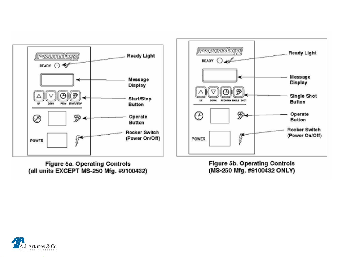
Green “Ready” light: It is located at the front of the unit and attached to the control board. When the
green light blinks, it indicates the generator is not up to temperature, therefore, the unit should not be cycled
during this time. When the green light is steadily on, it indicates the generator is up to operating temperature &
ready for use. When the light is off, it indicates the unit is in a steam cycle.
MS TECHNICAL MANUAL
LAST UPDATE 12-10-04
1060003 12/04
Page 25

TOOLS REQUIRED FOR PROPER TROUBLESHOOTING
(VOM) Volt Ohm Meter (digital or analog)
DC millivolt meter (unless integrated into VOM)
Clamp type amp meter (digital or analog)
Flat blade screwdriver ¼ ", 3/16"
Open end wrench ½"
Adjustable wrench 6"
¼“ ratchet and socket
Channel locks
Wire cutter, crimper, stripper
Wire brush
Needle nose pliers.
Temp meter with wire type thermocouple or surface type pyrometer
(must be able to read 500° F (260 °C) or more
Baking soda & powdered lime & mixing container
Teflon Tape
Hi temp Dow Corning #736 RTV
Portable vise
MS TECHNICAL MANUAL
LAST UPDATE 12-10-04
1060003 12/04
Page 26

MS TECHNICAL MANUAL
LAST UPDATE 12-10-04
1060003 12/04
Page 27

MS TECHNICAL MANUAL
LAST UPDATE 12-10-04
1060003 12/04
Page 28

MS TECHNICAL MANUAL
LAST UPDATE 12-10-04
1060003 12/04
Page 29

FIGURE 8
MS TECHNICAL MANUAL
LAST UPDATE 12-10-04
1060003 12/04
Page 30

MS TECHNICAL MANUAL
LAST UPDATE 12-10-04
1060003 12/04
Page 31

TROUBLE SHOOTING
Problem Possible Cause Corrective Action
Control Display is Blank (power On/Off
switch is On but indicator light is off).
Control Display is blank (power On/Off switch
is on and indicator light is on).
Unit does not heat up (Control Display is on)
The power cord is not correctly plugged in. Plug the power cord into the appropriate
outlet.
The power cord and/or electrical plug is
damaged.
The main electrical panel circuit breaker is off
or has been tripped.
Switch is inoperable. See parts testing and
Control Board is inoperable
Transformer is inoperable.
Loose, burnt, or broken wires in cir-cuit.
Hi-Limit Thermostat is tripped or inoperable.
Inspect electrical wire, plug, and receptacle.
Reset circuit breaker. See parts testing and
replacement section of this manual
replacement section of this manual
See parts testing and
replacement section of this manual
““““
““““
Reset the Hi-Limit Thermostat according to the
Operations sec-tion of this manual. If the
Hi-Limit Thermostat requires continuous
resetting, See parts testing and
replacement section of this manual
The unit’s main electrical panel cir-cuit breaker
trips.
Solid State Relay is inoperable.
Thermocouple is inoperable.
Control Board is inoperable.
Steam Generator is inoperable.
Loose, burnt, or broken wires in cir-cuit.
Damaged receptacle, plug, or cord; a loose
connection or an internal component failure.
MS TECHNICAL MANUAL
LAST UPDATE 12-10-04
““““
““““
““““
““““
““““
Turn the unit off, allow it to cool to room
temperature, and then restart the unit.
See parts testing and
replacement section of this manual
1060003 12/04
Page 32

TROUBLE SHOOTING
Problem Possible Cause Corrective Action
Water leaking inside electrical
hous-ing.
“ERR” appears in the Control
Display.
Pinhole leak in rubber hoses
(MS-150/155/355).
Loose or damaged water line
tubes and/or fittings inside
electrical hous-ing.
Programming and/or SHO and
H2O values were
adjusted/changed improperly.
Replace hoses.
Apply teflon tape, Tighten or
replace tubes and/or fit-tings.
Reset the Control Board as
described in the Programing
section of this manual.
MS TECHNICAL MANUAL
LAST UPDATE 12-10-04
1060003 12/04
Page 33

TROUBLE SHOOTING
Problem Possible Cause Corrective Action
Unit heats but there is little or no steam
produced
and/or
The product requires more steaming than
usual.
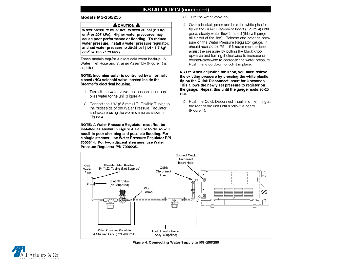
Water Line Valve is closed (MS-250/255). Check that the Water Line Valve is Open
Filter Strainer is restricted. Check and clean the Filter Strainer.
Quick disconnect is not fully engaged at
rear of the unit or is damaged
(MS-250/255).
Low or no water pressure in the water line
(MS-250/255).
Improper water pressure to unit
(MS-250/255).
Remove and reengage the Quick
Disconnect firmly until a “click” is heard.
Replace if damaged.
Remove the Quick Disconnect Insert from
the rear of the unit. While holding over an
empty cup, press the white plastic tip.
Strong, steady water flow should be noted.
If so, reengage firmly into unit. If not
present, or pressure is low, contact your
maintenance person or plumber.
Verify that a Water Pressure Regulator is
installed and set to 20-25 PSI.
Unit is not being cleaned properly
(daily/monthly).
Programming and/or SHO, H2O values
were adjusted/changed improperly.
Insufficient or excessive calcium/mineral
deposits on the Generator surface.
MS TECHNICAL MANUAL
LAST UPDATE 12-10-04
Clean unit daily and monthly as described
in the Maintenance section of this manual.
Reprogram the SHO and H2O values .
Verify that thin layer of calcium/mineral
deposits is present on the Generator
surface.
1060003 12/04
Page 34

TROUBLE SHOOTING
Problem Possible cause Corrective action
MS TECHNICAL MANUAL
LAST UPDATE 12-10-04
1060003 12/04
Page 35

Parts Testing & Replacement Procedures
MS TECHNICAL MANUAL
LAST UPDATE 12-10-04
1060003 12/04
Page 36

Testing Power Switch
See Power Switch under “Component Description & Function” before proceeding.
TESTING POWER SWITCH
Disconnect wires to isolate switch.
Turn switch to the “On” position. Verify continuity across
terminals 1 & 2, then 4 & 5. Next, turn switch to the “Off”
position. Reading should now be infinity.
Replace if fails test.
4
5
2
1
Replacement Procedures
Disconnect power switch wires (Mark for reinstallation).
Squeeze locking tabs inward & push switch out towards front of unit.
Snap new switch into place until flush.
Reinstall wiring onto switch.
Test unit for proper operation.
MS TECHNICAL MANUAL
LAST UPDATE 12-10-04
1060003 12/04
Page 37

TESTING SQUARED MOMENTARY SWITCH
See Momentary Switch under “Component Description & Function” before proceeding.
TESTING SQUARED MOMENTARY SWITCH
Disconnect wires to isolate switch.
Press & hold switch in. Verify continuity across both terminals.
Next, release switch. Reading should now be infinity.
Replace if fails test.
Replacement Procedures
Disconnect switch wires.
Squeeze locking tabs inward & push switch out towards front of unit.
Snap new switch into place until flush.
Reinstall wiring onto switch.
Test unit for proper operation.
MS TECHNICAL MANUAL
LAST UPDATE 12-10-04
1060003 12/04
Page 38

TESTING STEPDOWN TRANSFORMER
See Transformer under “Component Description & Function” before proceeding
TESTING STEP DOWN TRANSFORMER
Disconnect wires to isolate transformer coils.
Terminals 1 & 2 (15-19 ohms)
Terminals 4 & 5 (17-23 ohms)
Terminals 6 & 10 (0.6 ohms)
Terminals 6 & 8 (0.3 ohms)
Terminals 8 & 10 (0.3 ohms)
All readings +/- 10%
Replace if any coil fails test.
6
8
10
1
2
4
5
Replacement Procedures
Disconnect transformer wires (Mark for reinstallation).
Remove the 2 screws beneath the transformer.
Install new transformer & secure into place with screws.
Reinstall the wiring onto transformer.
Test unit for proper operation.
MS TECHNICAL MANUAL
LAST UPDATE 12-10-04
1060003 12/04
Page 39

TESTING CONTROL BOARD
See Control Board under “Component Description & Function” before proceedi n g.
TESTING CONTROL BOARD
Control Board must be tested while powered up
(See Technical Theory of Operation).
Check for proper VAC/VDC input & output.
Replace if it fails any of its functions.
Replacement Procedures
Disconnect control board wiring & unplug thermocouple
(Mark for reinstallation).
Remove the nuts & the control board.
Install new control board & secure with the nuts.
Reinstall the wiring & thermocouple onto control board.
Allow unit to heat up 15 minutes.
You must Program the control board per instruction sheet
(Included in kit) # 1010849.
NOTE: Failure to program upon install may result in
improper operation.
Test unit for proper operation.
MS TECHNICAL MANUAL
LAST UPDATE 12-10-04
1060003 12/04
Page 40

TESTING SS RELAY
See SS Relay under “Component Description & Function” before proceeding.
TESTING SS RELAY
To determine if relay contacts are stuck closed
(Unit overheating):
Disconnect RED wire from relay terminal 3 (+).
Clamp an amp meter onto the black wire at relay
terminal 1 or 2.
Is there any amp draw? If yes, replace relay.
To determine if relay contacts are stuck open
(Unit not heating):
Ensure the control board & relay are wired per
the wiring diagram.
Is 10-15 VDC present at relay terminals 3 (+)
& 4 (-)? If yes, is line voltage present across the
two generator terminals?
If no, replace relay.
2
1
3+
4-
Replacement Procedures
Disconnect the relay wiring (Mark for reinstallation).
Remove the two mounting screws & relay.
Install new relay with thermal compound (If included in kit).
Reinstall wiring onto relay.
Test unit for proper operation.
MS TECHNICAL MANUAL
LAST UPDATE 12-10-04
1060003 12/04
Page 41

TESTING GENERATOR
See Generator under “Component Description & Function” before proceeding.
TESTING GENERATOR
Disconnect wires to isolate generator.
Verify 13 ohms +/- 1 for 208 volt generator
Verify 16 ohms +/- 1 for 230 volt generator
Verify 8 ohms +/- 1 for 120 volt generator
Check from each terminal to ground using at least
a 20M scale. Reading should be infinity.
Replace if fails either test.
Replacement Procedures
Disconnect generator wiring.
Loosen brackets & remove thermocouple & hi-limit cap tube.
Remove compression nuts & steel tubes from the brass
elbow & “T” fitting. NOTE: Flexing the Teflon tubes may be required.
Unscrew (CCW) the brass elbow & fitting along with the teflon tubes
from the generator.
Remove generator wing nut, lid, & diffuser plate.
Remove the generator’s top 3 setscrews.
Cautiously, push the generator up & out of the chassis.
NOTE: Extra effort may be needed as generator is siliconed
onto the chassis.
Remove remaining dried silicone from chassis.
Apply 1/8” bead of red hi-temperature silicone (Supplied in kit) onto
the chassis &
the underside of the generator
MS TECHNICAL MANUAL
LAST UPDATE 12-10-04
1060003 12/04
Page 42

GENERATOR CONTINUED
NOTE: Failure to apply silicone will allow steam to enter the electrical compartment.
Seat new generator in place & secure with new setscrews.
NOTE: Replacement generator will have artificial lime deposits on it that are required for proper
steaming characteristics.
Remove excess silicone & smooth to a neat finish.
Apply Teflon tape to the threads of the Teflon tubes & screw into generator until snug.
Reinstall the steel tubes, compression nuts, & secure.
Reinstall wiring, thermocouple, hi-limit cap tube, brackets, & secure.
Allow unit to heat 15 minutes.
Run several cycles & check for leaks within electrical compartment. Repair if needed.
Reprogram the SHO & H2O settings if needed (See Programming Section).
Reinstall diffuser plate, lid, wing nut, & service panel.
NOTE: Silicone must be allowed to cure 12-24 hours before customer places unit into use.
MS TECHNICAL MANUAL
LAST UPDATE 12-10-04
1060003 12/04
Page 43

TESTING GENERATOR LID
See Generator Lid under “Component Description & Function” before proceeding.
Ensure the wing nut is tight.
Does noticeable steam leak out the perimeter of the cover?
If yes, remove cover, check it for flatness, & observe its underside.
Does the outer ½” perimeter contain any noticeable calcium buildup?
If yes, replace cover.
NOTE: Calcium buildup at perimeter indicates that steam is
leaking out from there. If perimeter is shiny, it indicates that
steam is not leaking.
NOTE: Gaskets are not used in MS series.
Replacement Procedures
Remove wing nut & lid.
Install new lid & secure with wing nut.
Test unit for proper operation.
MS TECHNICAL MANUAL
LAST UPDATE 12-10-04
1060003 12/04
Page 44

TESTING TYPE ”K” THERMOCOUPLE
See Thermocouple under “Component Description & Function” before proceeding
To test thermocouple for continuity: Unplug thermocouple from
control board to isolate it.
At room temperature, verify 2-3 ohms across red & yellow wire.
Replace if fails test.
To determine if an “overheating” or “under heating condition”
is caused by a faulty thermocouple:
Preheat unit for 15 minutes then monitor the generator’s surface, or
internal temperature. Next, unplug the thermocouple from the control
board. Set your VOM to the VDC scale, 50-200 MV (millivolt) range.
Using the provided millivolt chart, determine if the thermocouple is
generating the proper DC millivolts (+/- 1.0 millivolt) at the indicated
temperature. Quick Tip: If the unit is under heating, the DC millivolts
being generated will be much higher than what they should. If the
unit is overheating, the DC millivolts being generated will be much
lower than what they should be.
Replace if fails test.
Replacement Procedures
Unplug thermocouple from control board.
Loosen retainer bracket screw & remove from generator hole.
Install new thermocouple & secure to generator & control board.
Test unit for proper operation.
MS TECHNICAL MANUAL
LAST UPDATE 12-10-04
1060003 12/04
Page 45

TESTING HI-LIMIT
See Hi-limit under “Component Description & Function” before proceeding.
To test for continuity: Disconnect wires to isolate hi-limit.
Verify continuity across the terminals.
Replace if fails test.
To determine if hi-limit is tripping prematurely: Monitor the generator’s
surface or internal temperature.
Does hi-limit trip below 450 F (232 C)? If yes, replace hi-limit.
To determine if hi-limit is tripping too late, or not at all: Short relay
terminals 1 & 2 together (This simulates an overheating condition).
Monitor the generator’s surface or internal temperature.
Does the temperature exceed 610 F (321 C)? Is the generator still
drawing amperage? If yes, replace hi-limit.
NOTE: Reinstall any removed wiring to their original terminals.
Replacement Procedures
Disconnect hi-limit wires.
Remove lock nut & dismount the ceramic body.
Remove cap tube bracket & pull cap tube out of
generator hole.
Install new hi-limit & secure with bracket & lock nut.
Reinstall wiring onto hi-limit.
Test unit for proper operation.
MS TECHNICAL MANUAL
LAST UPDATE 12-10-04
1060003 12/04
Page 46

TESTING SOLENOID VALVE
(Direct water feed units only)
See Solenoid Valve under “Component Description & Function” before proceeding.
To test the solenoid valve coil: Disconnect wires to isolate solenoid
valve coil. Verify 8-20 ohms.
Replace if fails test.
To determine if solenoid valve is leaking through: Turn power off &
disconnect water line from rear.
Dry up any water that is present on the generator surface.
Once dry, reconnect the water line ONLY.
Does water begin to slowly flow onto the generator surface? If yes,
disassemble & clean out solenoid valve plunger.
If still leaks, replace solenoid valve.
To Clean: Remove top nut then slide coil assembly off.
Secure the valve body with channel locks.
If the valve stem is slotted at the top, loosen & remove the stem with a
sturdy screw driver. If it is not slotted, you will need the special hex nut
with locking pins.
Remove the plunger, spring, o’ring.
With a cloth, gently clean out the plunger & body area. Generally, the
debris/speck found will be small.
Reassemble items & recheck.
Replace if still leaks.
SEE PICTURES ON NEXT PAGE
MS TECHNICAL MANUAL
LAST UPDATE 12-10-04
1060003 12/04
Page 47

MS TECHNICAL MANUAL
LAST UPDATE 12-10-04
1060003 12/04
Page 48

REPLACING SOLENOID VALVE
See Solenoid Valve under “Component Description & Function” before proceeding.
Replacement Procedures
Disconnect solenoid valve wires.
Remove compression nuts & steel tubes from the
brass elbow & “T” fitting.
NOTE: Flexing the Teflon tubes may be required to
ease nut & tube removal.
Remove the two rear female quick disconnect screws.
Remove the solenoid/QD assembly.
Unscrew the QD from the solenoid valve body.
NOTE: Vise may be required.
Thread the QD into the new solenoid valve body.
NOTE: Apply thread sealant onto threads & verify
the “IN” & “OUT” on valve.
Reinstall solenoid/QD assembly & secure with screws.
Reinstall the steel tubes, compression nuts, & secure.
Allow unit to preheat 15 minutes.
Run several cycles & check for leaks within electrical
compartment. Repair if needed.
Test unit for proper operation.
MS TECHNICAL MANUAL
LAST UPDATE 12-10-04
1060003 12/04
Page 49

TESTING WATER PUMP
(Water Tank Equipped Models)
See Water Pump under “Component Description & Function” before proceeding
To Test Diode: Remove diode from pump.
Set your VOM to “Diode” check setting.
Measure across both diode terminals & note the reading. Next,
reverse your VOM leads on diode & measure again. Reading
should be infinity one way & 470-520 the other way.
Replace if fails test.
To Test Pump Coil: Remove diode from pump.
Verify 4-6 ohms across the 2 orange wires on pump.
Replace if fails test.
To determine if water pump is leaking through:
Turn power off & dry up any water that is present on the generator surface.
Once dry, fill the water tank with water. NOTE: Verify the tank filter is installed & not torn or damaged.
Does water begin to slowly flow onto the generator surface? If yes, disassemble & clean out the water pump.
If still leaks, replace water pump.
To Clean: Turn power off & unplug unit.
Drain the water tank.
Disconnect pump wires.
Disconnect rubber hoses from both ends of the pump.
Remove the pump’s bottom mounting nuts & remove pump.
Cautiously remove the pump’s two end plastic nipples.
NOTE: A check valve is behind each nipple. Make note of their color & position for proper reassembly.
Inspect both check valves. Replace if their rubber seal is torn or missing. If not torn, rinse in water.
Clean out the pump’s body with water & properly reinstall the check valves & end nipples.
Remount the pump & secure with the nuts. NOTE: Arrow on pump body should correspond with water flow
Reinstall the rubber hoses & wiring.
Verify the water tank filter is properly installed & not torn. Replace if needed. NOTE: MS-355 does not contain a water
filter.Fill tank with water & test for proper operation.
Replace both check valves or pump if continues to leak.
MS TECHNICAL MANUAL
LAST UPDATE 12-10-04
1060003 12/04
Page 50

REPLACING WATER PUMP
Water Tank Equipped Models
See Water Pump under “Component Description & Function” before proceeding
Replacement procedures
Turn power off & unplug unit.
Drain the water tank.
Disconnect pump wires.
Remove rubber hoses, bottom mounting nuts, & pump.
Install new pump assembly & secure with the nuts.
NOTE: Arrow on pump body should correspond with water flow
Reinstall rubber hoses & wiring.
Verify the water tank filter is properly installed & not torn. Replace if needed.
NOTE: MS-355 does not contain a water filter.
Fill tank with water & test unit for proper operation.
MS TECHNICAL MANUAL
LAST UPDATE 12-10-04
1060003 12/04
Page 51

TESTING QUICK DISCONNECT (FEMALE)
Direct Water Feed Units Only
See Quick Disconnect Female under “Component Description & Function” before proceeding
The Female QD is generally trouble free.
If the locking mechanism (Tab, spring, pin) are missing or
damaged, the female QD must be replaced.
Replacement Procedures
Disconnect the solenoid valve wires.
Remove compression nuts & steel tubes from the
brass elbow & “T” fitting.
NOTE: Flexing the Teflon tubes may be required
to ease nut & tube removal.
Remove the two rear female quick disconnect screws.
Remove the solenoid/QD assembly.
Unscrew the QD from the solenoid valve body.
NOTE: Vise may be required.
Thread new QD into the solenoid valve body.
NOTE: Apply thread sealant onto threads & verify
the “IN” & “OUT” on valve.
Reinstall solenoid/QD assembly & secure with screws.
Reinstall the steel tubes, compression nuts, & secure.
Allow unit to preheat 15 minutes.
Run several cycles & check for leaks within electrical
compartment. Repair if needed.
Test unit for proper operation.
MS TECHNICAL MANUAL
LAST UPDATE 12-10-04
1060003 12/04
Page 52

TESTING QUICK DISCONNECT (MALE)
Direct Water Feed Units Only
See Quick Disconnect Male under “Component Description & Function” before proceeding.
Verify the white nylon tip is not chipped, broken, or
damaged.
NOTE: The tip should protrude at least 1/8”.
Verify it retracts when depressed, & protrudes when
released.
NOTE: If water does not flow when the tip is depressed,
it generally indicates there is no water pressure in line.
If the quick disconnect leaks while engaged to the rear of the
unit, the o’ring is worn or damaged & must be replaced.
Replace if fails test
Replacement Procedures
Shut off water line valve that is before the quick disconnect.
Remove clamp & quick disconnect from water line.
Install new quick disconnect & secure with clamp onto water line.
Turn water line valve on & inspect for leaks. Repair if necessary.
Engage the quick disconnect into rear of steamer until a “Click” is
heard.
Operate unit for several cycles to purge air from line.
Test unit for proper operation
MS TECHNICAL MANUAL
LAST UPDATE 12-10-04
1060003 12/04
Page 53

TESTING AUDIO SIGNAL
See Audio Signal under “Component Description & Function
Does the audio sound for 3 seconds towards
the end of a cycle? If no, did the yellow (Audio)
Led turn on for 3 seconds? If yes, replace audio
signal.
Replacement Procedures
Using a small screw driver, straighten the locking
pin behind the audio signal.
Pull & remove audio signal.
Install new audio signal & bend locking pin down.
Test unit for proper operation.
MS TECHNICAL MANUAL
LAST UPDATE 12-10-04
1060003 12/04
Page 54

THERMOELECTRIC VOLTAGE IN MILLIVOLTS
TYPE “K” THERMOCOUPLE READINGS + OR – 1 MILLIVOLT
° F MV ° F MV ° F MV
300 6.1
310 6.3
320 6.5
330 6.7
340 6.9
350 7.2
360 7.4
370 7.6
380 7.8
390 8.0
400 8.3
410 8.5
420 8.7
430 8.9
440 9.2
450 9.4
460 9.6
470 9.8
480 10.1
490 10.3
500 10.5
510 10.7
520 11.0
530 11.2
540 11.4
550 11.7
560 11.9
570 12.1
580 12.3
590 12.6
600 12.8
MS TECHNICAL MANUAL
LAST UPDATE 12-10-04
1060003 12/04
Page 55

MS TECHNICAL MANUAL
LAST UPDATE 12-10-04
1060003 12/04
Page 56

MS TECHNICAL MANUAL
LAST UPDATE 12-10-04
1060003 12/04
 Loading...